

Submitted:
24 July 2026
Posted:
27 July 2026
You are already at the latest version
Abstract
Hybrid composite lattice structures have emerged as a promising approach for improving the impact resistance of lightweight aerospace components. This study investigates the influence of density-gradient direction in metallic Body-Centred Cubic (BCC) lattice reinforcement on the bird-strike response of a composite UAV leading-edge (L.E) structure. Three lattice architectures uniform, backward graded, and forward graded were parametrically generated using Rhino/Grasshopper and integrated within a carbon-fibre-reinforced polyamide L.E. The hybrid structures were analysed using Abaqus/Explicit with a validated Smooth Particle Hydrodynamics (SPH) bird model (1 kg, 95 m/s). All configurations maintained nearly identical structural mass, enabling the influence of lattice density distribution on structural response to be isolated. The backward graded configuration promoted progressive plastic collapse, resulting in the highest lattice energy absorption but also increased deformation and load transfer to the spar. In contrast, the forward graded configuration suppressed progressive collapse, confined deformation near the impact interface, and significantly reduced stress transmission to critical structural components. Peak displacement and spar energy transfer were reduced by approximately 95% and 90%, respectively, compared with the backward graded configuration. The results demonstrate that density-gradient tailoring of metallic lattice reinforcement enhances the structural performance of hybrid composite-lattice L.E structures by improving load sharing, deformation control, and impact resistance without increasing structural mass.
Keywords:
hybrid composite structures
; bird Strike
; functionally graded lattice
; load transfer mechanism
; UAV leading edge
; finite element analysis
1. Introduction
Lightweight composite L.E structures are widely employed in modern aircraft because of their high specific stiffness, corrosion resistance, and weight-saving potential. However, their relatively low resistance to localized high-velocity impact makes bird strike one of the most critical certification challenges for aerospace structures. Therefore, authorities such as the Federal Aviation Administration (FAA) demand that aircraft structures withstand bird impact without catastrophic failure. Due to their exposed position and aerodynamic function, L.Es are especially vulnerable to high-velocity soft-body impacts, which can result in severe structural damage. According to the certification requirements for L.E structures, even if the skin is penetrated, no critical damage should occur to the front spar or wing box, thereby ensuring continued safe flight and landing after impact, with no compromise on flight safety [1,2,3,4]. Furthermore, the structural stiffness characteristics of aircraft wings influence their aerodynamic performance, and impact-induced deformation of leading-edge structures may adversely affect the overall wing behaviour during flight. Therefore, improving the bird-strike resistance of L.E structures remains an important consideration in lightweight aerospace design [5].
Traditional approaches to improve impact resistance include the use of metallic reinforcements, composite laminates, and sandwich structures with foam or honeycomb cores. For example, B. Arachchige et al. [6] numerically investigated sandwich composite L.E with foam and honeycomb cores under bird impact at 80 m/s, reporting that honeycomb reinforcement reduced deflection by 85% compared to the unreinforced case. Moreover, laminate orientation was critical, with quasi-isotropic layups outperforming cross-ply for honeycomb, while the opposite trend was observed for foam cores. Guida et al.[7] analysed fibre metal laminate (FML) L.E designs using experimental and numerical methods and according to his findings FML structures effectively protected internal components and satisfied certification requirements. The FML 3/2 configuration showed superior impact resistance over FML 2/1 due to higher aluminium ply content, resulting in greater energy absorption and reduced deformation. Similarly, Jun Liu et al. [8] proposed a triangular reinforcement concept for L.E structures to improve bird-strike resistance and he analysed both numerically and experimentally. The results showed that the design effectively redistributes impact energy, reducing local deformation and damage and no penetration was observed in the frontal beam, demonstrating compliance with CCAR Part 25 certification requirements. However, these solutions provide a certain level of efficient structural performance, and they often suffer from limitations such as increased weight, limited tunability, and poor damage tolerance under localized high-velocity impacts. Comprehensive reviews by Abrate [9] have highlighted the challenges associated with achieving both lightweight design and high impact resistance. Although these reinforcement concepts improve impact resistance, they generally rely on homogeneous core architectures whose mechanical response cannot be locally tailored to simultaneously satisfy lightweight design and controlled load transfer within hybrid composite structures.
Consequently, lattice structures enabled by additive manufacturing (AM) have emerged as a promising alternative for impact applications. Additively manufactured metallic lattice structures provide an attractive reinforcement strategy for composite components because their topology and relative density can be tailored independently of the surrounding composite skin. Foundational work done by Gibson and Ashby [10] and subsequent studies have demonstrated the potential of cellular materials for lightweight applications. Recently, researchers had keen interest on the use of lattice structures in aerospace components subjected to impact loading. Yadong Zhou et al. [11] analysed the bird impact on a composite sandwich curved panels with three different configuration lattice, foam, and hybrid cores. Sandwich configurations significantly reduced back-faced deformation compared to monolithic plates, that significantly enhancing the structural protection. Similarly, Nasrullah et al. [12] presents the limitations of traditional crashworthy structures, such as honeycomb (anisotropic behaviour) and metallic foam (irregular geometry). According to this study, these structures have good energy absorption capacity however lattice structures fabricated with AM offer superior energy absorption. Moreover, results of this study suggested that optimization led twisted octet lattice achieving up to 127 kJ/kg specific energy absorption, demonstrating strong potential for crashworthy applications.
Functionally graded lattice structures, in which the relative density varies spatially, have been proposed as an effective strategy to enhance the structural performance. Studies such as Maskery et al. [13] have shown that density grading can improve the distribution of deformation and delay structural failure. Jan et al. [14] examines the mechanical behaviour of BCC lattice structures under bending and compression for lightweight aerospace applications. Functionally graded BCC lattices showed significantly improved performance, with bending load increased by up to 62.5% compared to uniform structures. The structures exhibited a dual failure mode (buckling followed by fracture), with strong agreement observed between experimental and numerical results. However, most existing work primarily focuses on maximizing energy absorption, with limited attention given to the control of load transfer to critical structural components such as spars. Similarly, Gurudev et al. [15] proposes a multi-objective optimization framework for density-graded BCC lattice structures, simultaneously addressing impact energy absorption and thermal dissipation. In bird strike scenarios, protecting the primary load-carrying structure is often more critical than maximizing energy dissipation alone. Excessive penetration or premature collapse of energy-absorbing components can lead to increased load transmission and potential damage to internal structures. Therefore, understanding how density grading influences not only energy absorption but also load transfer mechanisms is essential for designing efficient impact-resistant structures.
Beyond improving energy absorption, density-gradient tailoring provides a means of controlling stiffness distribution within hybrid composite lattice structures, thereby influencing deformation localization and load transfer during impact. Although metallic lattice reinforcement has shown considerable potential for improving the impact resistance of composite structures, the influence of density-gradient direction on the load-sharing behaviour between the metallic lattice core and the surrounding composite structure during bird strike remains poorly understood. In particular, the mechanisms by which density-gradient tailoring modifies deformation localization, stress transmission, and load transfer within hybrid composite-lattice structures have not been systematically investigated.
Accordingly, this study investigates how density-gradient tailoring of metallic BCC lattice reinforcement governs deformation localization, load sharing, and structural protection within a hybrid composite UAV leading-edge structure subjected to bird-strike loading. Three representative density distributions (uniform, backward graded, and forward graded) were developed using a parametric modelling approach in Rhino/Grasshopper, enabling controlled variation of the relative density along the impact direction while maintaining a constant strut thickness. The structural response was evaluated using explicit finite element analysis in Abaqus/Explicit with an SPH bird model validated against experimental data reported in the literature. The study focuses on the interplay between lattice deformation, energy absorption, and load transfer to the spar through a comparison performed under nearly identical structural mass, thereby isolating the effect of density-gradient direction on structural performance.
This paper is organized as follows: Section 2 presents the validation of the SPH bird model against experimental data. Section 3 describes the materials, lattice design methodology, and numerical modelling approach. Section 4 discusses the influence of density-gradient direction on deformation, energy absorption, damage evolution, stress distribution, and load-transfer mechanisms. Finally, the main findings and design implications are summarized in Section 5.
2. Bird Model Validation
The Smooth Particle Hydrodynamics (SPH) formulation, which is widely adopted for simulating soft-body impact phenomena, is employed in this work to model the bird projectile . The numerical framework, including the bird material definition, equation of state, and discretization strategy, follows the approach previously developed by authors (Currently under review). Moreover, the bird model used in this work is validated against experimental data of Lavoie et al. [16]. This validation step is important because it will increase the reliability of the numerical model used in the present analysis. For validation following numerical model is used as presented in Figure 1.
In the referenced validation study, the SPH bird model is calibrated using experimental impact tests involving a 1 kg projectile impacting a rigid target at the speed of 95 m/s. The comparison demonstrated good agreement in terms of deformation behaviour as presented in Figure 2, velocity decay, and material spreading during impact, confirming the capability of the model to reproduce the key characteristics of soft-body impact events.
Although the adopted SPH bird model has been previously validated against experimental deformation patterns, the present study extends this validation by including additional quantitative comparisons. In particular, the evolution of velocity (Figure 3a) and radial expansion (Figure 3b) of the bird during impact are evaluated and compared with experimental and reference numerical data. The results demonstrated strong agreement in terms of velocity decay and diameter growth. Therefore, these results confirming that the model accurately captures momentum transfer and material flow during impact. This extended validation further strengthens the reliability of the numerical framework used in the present analysis.
3. Materials and Methodology
3.1. Geometry and Model
The structure analysed in this study corresponds to the initial root section of a UAV wing, which is attached to the fuselage (see Figure 4 ). This type of UAV falls within the medium-mass category, with a maximum weight at the time of take-off (MTOW) is150 kg, placing it in the 50-200 kg range vehicles. Moreover, It is also classified as a close-range aircraft in terms of both operational distance and flight duration, a category that has gained considerable attention in civil and military applications due to its endurance and stable flight characteristics.
3.2. Lattice Design and Density Grading
The adopted design and analysis framework basically consists with three principal stages, parametric lattice generation, density grading definition, and finite element evaluation. The overall workflow, illustrated in Figure 5, provides a structured pipeline in which the L.E CAD geometry is first imported and used to define the lattice design space. A parametric voxelisation grid is then generated within this domain, enabling controlled spatial variation of lattice parameters. The BCC topology is selected and trimmed to conform to the external L.E. surface. The resulting lattice geometry is meshed and exported in STL format for subsequent finite element analysis in Abaqus/Explicit. Performance is evaluated in terms of lattice energy absorption, spar energy, and structural displacement, with the goal of identifying the optimal density grading strategy for bird-strike-resistant design.
The spatial variation of lattice density is controlled through the Graph Mapper component in Grasshopper, which defines the relationship between normalised position along the impact direction (from the outer L.E. surface toward the spar, x/L ∈ [0, 1]) and the local unit cell size. Three different types of mapping functions utilised to generate the configurations under investigation, as presented in Figure 6.
For the uniform configuration (Figure 6a), a linear mapping function is applied, in which the unit cell size remains constant across the full domain. The Graph Mapper curve is a straight horizontal line at a fixed normalised cell size value, producing a homogeneous relative density distribution throughout the lattice. This configuration serves as the reference baseline.
The backward graded configuration (Figure 6b) is controlled by a concave mapping function, in which the curve descends steeply near x/L = 0 (the impact surface) and levels off toward x/L = 1 (the spar). This produces large unit cell sizes and therefore low relative density near the outer surface, transitioning progressively to smaller, denser cells toward the rear of the structure. The result is a soft, compliant front region with a stiffer internal zone.
Furthermore, the forward graded configuration (Figure 6c) employs a convex mapping function, in which the curve rises steeply near x/L = 0 and plateaus at higher cell-size values toward x/L = 1. This produces small unit cells and therefore high relative density at the impact interface, transitioning to larger, more compliant cells in the interior. The resulting stiffness distribution concentrates resistance at the point of first contact, which is hypothesised to limit penetration and reduce load transfer to the spar. Across all three configurations, the strut thickness is held constant at 1.5 mm to ensure that differences in structural response are completely due to the density distribution.
The lattice structure was generated by repeating the unit cell within the internal volume of the L.E geometry (Figure 7). The dimensions of the L.E used for lattice generation along the x-, y-, and z-directions are 92.6 mm, 600 mm, and 85 mm, respectively. The geometric configuration of the lattice was controlled through parametric inputs, enabling spatial variation of the unit cell size. Moreover, the strut thickness was kept constant at 1.5 mm for all design configurations to ensure a consistent and reliable comparison. This variation directly influences the relative density of the lattice, where smaller cell sizes correspond to higher relative density and increased local stiffness.
The application of the three Graph Mapper functions to the L.E. geometry gives the three lattice configurations presented in Figure 8. Side views of the BCC lattice type networks are shown for each case, that shows the differences in cell size distribution along the impact direction.
In the uniform configuration (Figure 8a), the unit cell size is constant throughout the domain, producing a visually regular and spatially homogeneous lattice. The cell edges are of equal length across the full chord depth, reflecting the linear mapping function.
In the backward graded configuration (Figure 8b), the cells near the outer surface (right side of the image) are visibly larger and more open with dimension of 40mm, while cells near the spar (left side) are progressively smaller and denser with dimension of 22mm. This spatial gradient is a direct consequence of the concave Graph Mapper function, which assigns large cell sizes at x/L = 0 and reduces them toward x/L = 1. The density gradient extends progressively from a sparse, low-stiffness front region to a compact, high-stiffness rear region.
In the forward graded configuration (Figure 8c), the opposite distribution is observed: the cells at the impact interface are the smallest and most densely packed with dimension of 22mm, while those toward the spar are larger and more open with dimension of 40mm. The convex mapping function concentrates material at the outer surface, producing a dense, stiff front layer that transitions smoothly to a more compliant internal structure. This configuration is designed to resist the initial impulse of the bird strike, preventing penetration and limiting load transmission to the spar.
Moreover, The average relative density of each lattice architecture was calculated as the ratio of the lattice volume to the solid L.E envelope volume. The uniform configuration exhibited an average relative density of 0.652%, whereas the backward and forward graded configurations exhibited 0.673% and 0.536%, respectively. Since density grading was implemented by continuously varying the unit cell size along the impact direction, these values represent the average relative density of the complete lattice architecture. Local relative density varies spatially within the graded configurations, with smaller unit cell sizes corresponding to higher local relative densities and vice versa.
3.3. Numerical Model
The numerical model adopted in this study represents a wing L.E section comprising an outer composite skin supported by internal reinforcements as shown in Figure 9. In the outboard regions, a composite infill is introduced between the skin and internal structure to ensure structural continuity. However, the forward region of the wing or L.E region, is intentionally maintained as a hollow domain to allow the integration of alternative internal configurations. Within this region, the previously describe lattice structures are embedded, enabling a targeted investigation of the L.E response under impact loading. The baseline characteristics of the remaining wing structure is preserved to maintain the original airfoil shape.
To ensure efficient load transfer between the lattice core and the composite skin, a thin metallic interface layer with a thickness of 0.1 mm is introduced. All structural components, including the lattice, skin, reinforcements, and interface layer, are connected using tie constraints to enforce full displacement compatibility. All translational degrees of freedom (U1 = U2 = U3 = 0) were constrained at the wing root to represent the structural attachment conditions. Rotational degrees of freedom were not considered because the three-dimensional solid continuum elements employed in Abaqus inherently possess only translational degrees of freedom.
The bird strike event is simulated using a Smooth Particle Hydrodynamics (SPH) formulation. All contact interactions between the SPH bird model and the structural components were defined using the General Contact algorithm in Abaqus/Explicit. A hard contact was adopted in the normal direction with separation permitted after contact, whereas tangential behaviour was modelled using a penalty friction formulation with a constant coefficient of friction of 0.2.Based on established literature [16], bird mass of 1 kg is considered, and the impact velocity of 95 m/s was selected to represent the design cruise speed of the UAV under investigation. Moreover, this velocity falls at the upper boundary of the medium-speed bird strike regime (0-100 m/s) [17,18], and it is representative of the most critical in-flight impact scenario for this UAV class, in accordance with the general certification principle established by FAR 25.571 [19] . The total simulation time is set to 0.01 s to capture the complete impact event and subsequent structural response, and numerical stabilization is ensured through the activation of distortion control and element deletion, with element removal triggered at a damage parameter value of 0.95.
The structural components of the wing, including the composite skin and internal reinforcements, are discretized using reduced-integration hexahedral elements (C3D8R). The lattice structure is meshed using first-order tetrahedral elements (C3D4), while the thin metallic interface layer is modelled using shell elements (S4R), which are suitable for representing thin structures with bending behaviour.
Moreover, the internal lattice structure and the thin interfacial layer connecting the lattice to the outer skin is modelled using aluminium alloy AlSi10Mg. The AlSi10Mg material is represented using an elastic-plastic constitutive law with isotropic hardening [20]. The plastic behaviour is defined through literature-derived true stress-plastic strain data implemented in tabular form within Abaqus, as shown in Figure 10. The constitutive response represents the elastic-plastic hardening behaviour of the additively manufactured alloy [21]. Ductile damage initiation is defined using the Abaqus ductile damage criterion based on fracture strain, stress triaxiality, and strain rate dependence. Furthermore, an energy-based damage evolution law with a fracture energy of 67 N/mm is adopted to capture progressive material degradation and element deletion during impact loading. Aluminium materials properties are presented inTable 1.
All remaining structural components of the wing, including the external skin, internal reinforcements, closing frame, and root regions used for boundary condition application, are manufactured from carbon fibre-reinforced polyamide (CF/PA) composite [22] and mechanical properties are listed in Table 1. The CF/PA material is composed of a polyamide matrix reinforced with approximately 15% randomly distributed chopped carbon fibres. This composition leads to a substantial reduction in density compared to conventional metallic materials, while still maintaining adequate structural strength. The presence of carbon fibres enhances the stiffness and thermal stability of the material relative to unreinforced polymers, making it well-suited for lightweight structural applications. The composite was modelled using an elastic-plastic constitutive law combined with ductile damage initiation and energy-based damage evolution. Furthermore, CF/PA composite employed in this study was modelled as a homogenized isotropic material , consequently, the von Mises stress criterion provides an appropriate scalar measure for evaluating and comparing the stress distribution within the composite skin under bird-strike loading. The stress-strain data is considered according to the following curve (Figure 11) [22] .
3.4. Mesh Convergence Study
A representative BC-cubic lattice specimen was selected for the mesh sensitivity study, as it captures the characteristic deformation and load-transfer mechanisms occurring at the strut junctions during compressive loading. The specimen comprised periodically repeated BC-cubic unit cells subjected to quasi-static uniaxial compression between rigid loading plates, providing a computationally efficient and representative model for assessing mesh convergence. Five global element sizes: 0.8 mm, 1.0 mm, 1.2 mm, 1.4 mm, and 1.6 mm, while keeping all other modelling parameters unchanged. The convergence assessment is performed using the absorbed energy and force-displacement responses as shown in Figure 12.(a), and Figure 12.(b) respectively. The absorbed energy curves obtained for different mesh densities exhibit gradual reduction in numerical variation is observed with mesh refinement, whereas the difference between the 1.2 mm, 1.0 mm, and 0.8 mm meshes becomes comparatively small. This indicates that the numerical solution approaches mesh-independent behaviour for element sizes equal to or smaller than 1.2 mm.
A similar trend is observed in the force-displacement response, although minor differences exist in the post-peak crushing response for the finest mesh, the overall deformation behaviour and peak force predictions converge for meshes of 1.2 mm and below. The 0.8 mm mesh exhibits slightly higher stiffness due to improved resolution of local deformation and stress concentration regions.
Considering both numerical accuracy and computational cost, a global element size of 1.2 mm is selected for all subsequent solid-element simulations. The selected mesh provides stable predictions of deformation and energy absorption while significantly reducing computational expense compared to finer meshes.
4. Results and Discussion
4.1. Global Impact Response
The global impact response of the three lattice configurations exhibits completely different deformation and failure mechanisms, primarily governed by the spatial distribution of lattice density. Figure 13 presents the overall structural response under bird strike loading for the uniform, backward graded, and forward graded configurations.
In the uniform configuration (Figure 13a), localized damage is observed at the impact region, characterized by moderate cracking and deformation of the outer skin. The bird partially penetrates the structure, but the internal lattice provides some resistance, limiting the extent of intrusion. The damage remains relatively confined to the central impact zone, indicating a balanced response between stiffness and energy absorption.
The backward graded configuration (Figure 13b) exhibits significantly more severe damage. The outer skin undergoes extensive failure, and the bird penetrates deeply into the structure, as clearly visible in both side and front views. The low-density impact region undergoes premature plastic collapse, resulting in localized cell buckling and the formation of a transmissive load path that facilitates stress propagation toward the spar. This results in a widespread damage pattern and indicates a clear transmission of impact energy toward the spar region which is described in following section. On the other hand, the forward graded configuration (Figure 13c) demonstrates fundamentally different behaviour, as no visible penetration occurs, and the deformation is minimal and primarily confined to the outer surface. The higher local stiffness at the impact interface promotes more effective impact load transmission and suppresses premature cell buckling, thereby confining plastic deformation within the contact zone and reducing load transfer to the spar. As a result, the internal lattice and supporting structures remain largely intact, and the damage is negligible compared to the other configurations.
A comparison of these responses tells the critical role of density distribution in governing impact behaviour. The backward graded design promotes progressive collapse and internal energy dissipation but at the expense of structural integrity and penetration resistance. The uniform configuration provides moderate resistance, while the forward graded design acts as a protective barrier, preventing penetration and preserving the integrity of internal components. These observations establish that the direction of lattice grading directly influences the failure mechanism, ranging from penetration-dominated behaviour in backward grading to impact-resistant behaviour in forward grading. This distinction forms the basis for the subsequent quantitative analysis of energy absorption and load transfer.
4.2. Structural Deformation and Displacement
The deformation response of the L.E structure is evaluated using both global displacement time histories and full-field displacement contours (U1 component). This combined assessment enables identification of both the magnitude and spatial distribution of deformation, which are critical for understanding penetration mechanisms and structural integrity under impact loading.
The displacement-time histories as presented in Figure 14 reveal different deformation characteristics for the three configurations. The uniform configuration exhibits a rapid increase in displacement during the initial impact phase, reaching a peak value of approximately 77 mm, followed by a gradual stabilization. This behaviour indicates significant structural compliance and partial collapse in the impact region. The backward graded configuration shows a similar trend, with a slightly lower peak displacement of approximately 73 mm, but with a more pronounced oscillatory response during the early stages of impact. This suggests a less stable load-bearing mechanism, associated with progressive collapse of the low-density front region and delayed engagement of the stiffer internal structure. However, in forward graded configuration a completely different response is observed, with a maximum displacement limited to approximately 3.8 mm. The absence of significant deformation indicates a highly stiff structural response, effectively resisting the impact without undergoing collapse. In quantitative comparison the uniform configuration, the forward graded lattice reduces the peak displacement by approximately 95%, decreasing from 77 mm to 3.8 mm. Similarly, a reduction of nearly 94.8% is observed relative to the backward graded configuration.
Moreover, the spatial distribution of displacement as shown in Figure 15 provides critical insight into the underlying deformation mechanisms. Uniform density configuration shows a localized but clearly developed deformation zone at the impact location, with peak U1 values approaching 90 mm. The deformation is primarily concentrated in the central region, with limited propagation along the longitudinal direction. This indicates that the structure undergoes localized indentation and partial penetration, while still maintaining some load distribution capability.
But in backward graded configuration exhibits a larger deformation zone with higher displacement magnitude, exceeding ~100 mm. Unlike the uniform case, the deformation spreads over a wider region, indicating a loss of structural confinement. This behaviour is directly attributed to the reduced stiffness at the impact interface, which promotes early lattice collapse and allows deeper penetration before load redistribution occurs. But in the forward graded configuration, the displacement field is significantly reduced and smoothly distributed, with values remaining below 1 mm. So that, no localized deformation or indentation is observed. Instead, the structure behaves as a stiff continuous medium, where the applied load is distributed over a broader area without triggering local failure.
The displacement data collectively establish a clear performance hierarchy the forward graded configuration reduces peak displacement from 77 mm (uniform) and 73 mm (backward graded) to 3.8 mm a reduction of 95% and 94.8%, respectively while the backward graded configuration offers no displacement advantage over the uniform design despite absorbing 6.2 times more energy. This confirms that deformation is governed by local stiffness at the impact interface rather than global structural compliance.
4.3. Plastic Deformation and Damage Evolution
To obtain a comprehensive understanding of the structural response, both equivalent plastic strain (PEEQ) Figure 16 and ductile damage initiation (DUCTCRT) Figure 17 are analysed. While PEEQ characterises the extent and distribution of plastic deformation, DUCTCRT identifies the onset of material failure. The combined evaluation enables a direct link between deformation mechanisms and structural integrity.
The uniform configuration exhibits moderate plastic strain confined to the impact region, with limited spatial propagation. The corresponding DUCTCRT results indicate localized damage initiation, suggesting that although plastic deformation occurs, it does not extensively evolve into structural failure. This reflects an unoptimized response where deformation is neither effectively dissipated nor fully controlled.
In the backward graded configuration, high PEEQ values are observed at the impact interface, indicating rapid yielding of the low-density front region. This localised plasticity propagates inward, forming collapse bands within the lattice. Correspondingly, the DUCTCRT field shows widespread regions approaching the damage threshold, confirming that the accumulated plastic strain transitions into ductile failure. This behaviour demonstrates that deformation is not only significant but also leads to structural degradation.
However, the forward graded configuration shows minimal PEEQ across the structure, indicating suppression of plastic deformation. The DUCTCRT field remains near zero, confirming that damage initiation is effectively prevented. This behaviour is attributed to the higher stiffness of the front region, which restricts deformation and preserves structural integrity. These results demonstrate that structural performance is governed not only by the magnitude of plastic deformation but by its ability to evolve into damage. The backward graded configuration promotes plastic collapse leading to failure, whereas the forward graded configuration suppresses both plasticity and damage, resulting in superior structural protection.
These results establish a clear mechanistic hierarchy the backward graded configuration develops PEEQ levels sufficient to trigger ductile damage propagation throughout the lattice interior; the uniform configuration accumulates localised plastic strain that remains below the full damage threshold; and the forward graded configuration sustains a near-elastic response in which both PEEQ and DUCTCRT remain negligible across the entire domain. Structural performance is therefore governed not by the magnitude of plastic strain alone, but by whether that plastic deformation evolves into progressive material failure.
4.4. Energy Absorption Analysis
The energy absorption data quantitatively differentiate the three configurations Figure 18a. The backward graded lattice absorbs 110.9 J (specific energy: 20.73 J/kg), representing 6.2 times the energy absorbed by the uniform configuration (18.0 J; 3.36 J/kg) and 17.1 times that of the forward graded configuration (6.5 J; 1.22 J/kg). This difference reflects the progressive plastic collapse mechanism of the low-density front region, which engages a large deformation volume under the incoming impulse. However, spar energy transfers the more safety-critical metric tells a contrasting story Figure 18b. The forward graded configuration limits spar energy to 0.7 J (0.13 J/kg), which is 83% lower than the uniform configuration (4.1 J; 0.56 J/kg) and 90% lower than the backward graded configuration (6.8 J; 1.20 J/kg). Notably, the backward graded design transmits 66% more load to the spar than the uniform case despite its far superior lattice energy absorption, demonstrating that higher energy dissipation capacity does not imply improved structural protection.
This leads to a key trade-off in structural design. The backward graded configuration maximizes energy absorption but at the cost of increased load transmission and structural vulnerability. The forward graded configuration, despite absorbing less energy, provides superior protection by preventing penetration and minimizing load transfer to critical components. The uniform configuration offers a compromise between these two extremes.
4.5. Stress Distribution Analysis
The stress distribution of the three lattice configurations is further analysed to completely understand the load transfer mechanisms and structural response under impact. Figure 19 presents the von Mises stress contours for (a) outer composite skin, and (b) the metallic lattice structure.
The uniform configuration demonstrates a more localized stress distribution, primarily confined to the impact region with limited propagation into the lattice. In the absence of a stiffness gradient, the structure does not promote a controlled load redistribution mechanism. As a result, stresses remain concentrated near the point of impact, leading to localized deformation without effective attenuation or redirection of the load. This behaviour is consistent with the moderate spar energy and intermediate structural response observed in previous sections.
In the backward graded configuration, stress is initially concentrated at the impact interface but rapidly propagates into the interior of the structure. This behaviour is directly linked to the low-density front region, which undergoes early yielding as observed in the PEEQ results. The local reduction in stiffness following yielding facilitates stress transmission along the lattice network, resulting in a broader stress field extending toward the spar. This transmissive load path explains the higher energy transfer to the spar and the increased structural vulnerability observed in this configuration.
However, in forward graded configuration, it demonstrates a distinctly different stress pattern. High stress levels are localized at the outer surface, while the interior lattice remains largely unstressed. This is attributed to the higher density and stiffness of the front region, which resists deformation and prevents stress transmission into the internal structure. As a result, the load path is effectively confined to the outer layer, limiting the stress transmission into the interior structure. This localized stress response is consistent with the minimal plastic deformation and negligible damage observed in the PEEQ and DUCTCRT analyses.
These results confirm that the stress distribution is governed by the spatial variation of lattice stiffness. Configurations with a compliant front region promote stress propagation and structural collapse, whereas configurations with a stiff front region effectively confine stresses and protect internal components. Therefore, controlling the load path through density grading is a key design strategy for improving impact resistance in lattice-reinforced aerospace structures.
4.6. Mass-Normalized Performance Comparison
To ensure a fair comparison between the different lattice configurations, the results are further evaluated using mass-normalized performance metrics as shown in Table 2. Although the total mass variation is relatively small but in this kind of comparison it is essential to do mass normalized performance comparison. Therefore, specific energy metrics (energy per unit mass) are used to assess the efficiency of each design. Additionally, the observed mass variation of approximately 0.01 kg (<0.2%) is considered negligible and is attributed to geometric discretization associated with the parametric lattice generation methodology rather than intentional differences in the design configurations.
The mass-normalized analysis confirms the previous findings by eliminating the influence of weight variation. The backward graded configuration achieves the highest specific lattice energy, but also the highest specific spar energy, indicating inefficient energy dissipation accompanied by increased structural risk. The uniform configuration provides intermediate values, reflecting a non-optimized compromise. The forward graded configuration demonstrates the lowest specific spar energy and displacement, confirming that it provides the most efficient load attenuation mechanism per unit mass. These results are consistent with cellular material theory, in which the stiffness and strength of lattice structures depend on their relative density. However, the present study demonstrates that the spatial arrangement of density is more influential than the overall density itself, as it directly controls the deformation mechanism and the evolution of load transfer paths during impact.
5. Conclusion
This study investigated the influence of density-gradient direction in metallic BCC lattice reinforcement on the bird-strike response of a hybrid composite UAV leading-edge using an explicit finite element framework. Three representative lattice architectures uniform, backward graded, and forward graded were analysed under identical impact conditions while maintaining nearly identical structural mass, enabling the isolated effect of density distribution on structural behaviour to be evaluated.
The results demonstrated that the impact response is governed not simply by the amount of energy absorbed, but by the manner in which the density gradient controls deformation localization and load-path evolution. The backward graded configuration promoted progressive plastic collapse of the compliant front region, resulting in the highest lattice energy absorption (110.9 J). However, this collapse mechanism also produced severe deformation, extensive damage evolution, and the highest load transfer to the spar. Conversely, the forward graded configuration concentrated stiffness at the impact interface, suppressing progressive collapse and confining deformation to the outer region of the structure. Consequently, peak displacement and spar energy were reduced by approximately 95% and 90%, respectively, compared with the backward graded configuration, despite absorbing substantially less lattice energy.
The combined analyses of displacement, PEEQ, ductile damage, stress distribution, and mass-normalized performance consistently demonstrate that structural protection under bird-strike loading is governed primarily by load-transfer control rather than maximum energy absorption alone. Density-gradient direction determines whether impact loads are dissipated through progressive collapse or confined near the impact interface, thereby controlling stress propagation toward critical load-carrying components.
These findings establish density-gradient tailoring as an effective passive design strategy for improving the crashworthiness of hybrid composite-lattice aerospace structures without increasing structural mass. More broadly, the present work demonstrates that optimizing the spatial distribution of lattice density offers greater structural benefit than simply increasing the overall lattice density, providing new design guidance for lightweight impact-resistant aerospace structures manufactured using additive manufacturing technologies.
Limitations and Future Work
The present study is limited to a single BCC lattice topology and a specific bird-strike loading condition (1 kg, 95 m/s) evaluated through validated explicit finite element simulations. Manufacturing constraints associated with density-graded lattice architectures were not explicitly considered. Future work will focus on experimental validation, manufacturability assessments, alternative lattice topologies, and the influence of different bird masses, impact velocities, and multi-impact bird-strike scenarios.
Author Contributions
All authors equally contributed to this paper.
Funding
The authors received no specific funding for this work.
Data Availability Statement
The data supporting the findings of this study are available within the article. Additional data related to this work are available from the corresponding author upon reasonable request.
Acknowledgments
During the preparation of this work the author(s) used Open-AI in order to improve the language and readability. After using this tool, the author(s) reviewed and edited the content as needed and took full responsibility for the content of the published article.
Conflicts of Interest
The authors declare that they have no known competing financial interests or personal relationships that could have appeared to influence the work reported in this paper.
References
- Di Caprio, F.; Cristillo, D.; Saputo, S.; Guida, M.; Riccio, A. Crashworthiness of Wing Leading Edges under Bird Impact Event. Compos. Struct. 2019, 216, 39–52. [Google Scholar] [CrossRef]
- Guida, M.; Marulo, F.; Meo, M.; Riccio, M. Analysis of Bird Impact on a Composite Tailplane Leading Edge. Appl. Compos. Mater. 2008, 15, 241–257. [Google Scholar] [CrossRef]
- Di Caprio, F.; Sellitto, A.; Saputo, S.; Guida, M.; Riccio, A. A Sensitivity Analysis of the Damage Behavior of a Leading-Edge Subject to Bird Strike. Appl. Sci. 2020, 10, 1–18. [Google Scholar] [CrossRef]
- Guida, M.; Marulo, F.; Meo, M.; Russo, S. Certification by Birdstrike Analysis on C27J Fullscale Ribless Composite Leading Edge. Int. J. Impact Eng. 2013, 54, 105–113. [Google Scholar] [CrossRef]
- QIAO, S.; WANG, F.; WANG, P. A Numerical Study of the Impact of Bending and Torsional Stiffness on the Static Aeroelastic Characteristics of a Large Aspect Ratio Composite Wing. In INTERNACIONAL DE METODOS NUMERICOS PARA CALCULO Y DISENO EN INGENIERIA; 2024. [Google Scholar]
- Arachchige, B.; Ghasemnejad, H.; Yasaee, M. Effect of Bird-Strike on Sandwich Composite Aircraft Wing Leading Edge. Adv. Eng. Softw. 2020, 148, 102839. [Google Scholar] [CrossRef]
- Guida, M.; Marulo, F.; Polito, T.; Meo, M.; Riccio, M. Design and Testing of a Fiber-Metal-Laminate Bird-Strike-Resistant Leading Edge. J. Aircr. 2009, 46, 2121–2129. [Google Scholar] [CrossRef]
- Liu, J.; Li, Y.; Yu, X.; Tang, Z.; Gao, X.; Lv, J.; Zhang, Z. A Novel Design for Reinforcing the Aircraft Tail Leading Edge Structure against Bird Strike. Int. J. Impact Eng. 2017, 105, 89–101. [Google Scholar] [CrossRef]
- Abrate, S. Impact on Composite Structures; Cambridge, Cambridge , 1998. [Google Scholar]
- Zhong, H.; Song, T.; Li, C.; Das, R.; Gu, J.; Qian, M. The Gibson-Ashby Model for Additively Manufactured Metal Lattice Materials: Its Theoretical Basis, Limitations and New Insights from Remedies. Curr. Opin. Solid State Mater. Sci. 2023, 27, 101081. [Google Scholar] [CrossRef]
- Zhang, Y.; Zhou, Y. Investigation of Bird-Strike Resistance of Composite Sandwich Curved Plates with Lattice/Foam Cores. Thin-Walled Struct. 2023, 182, 110203. [Google Scholar] [CrossRef]
- Nasrullah, A.I.H.; Santosa, S.P.; Dirgantara, T. Design and Optimization of Crashworthy Components Based on Lattice Structure Configuration. Structures 2020, 26, 969–981. [Google Scholar] [CrossRef]
- Maskery, I.; Aboulkhair, N.T.; Aremu, A.O.; Tuck, C.J.; Ashcroft, I.A.; Wildman, R.D.; Hague, R.J.M. A Mechanical Property Evaluation of Graded Density Al-Si10-Mg Lattice Structures Manufactured by Selective Laser Melting. Mater. Sci. Eng. A 2016, 670, 264–274. [Google Scholar] [CrossRef]
- Jan, A.; Munir, A.; ul Haq, M.R.; Khan, M.S.; Kaleem, A.; Ahsan, M.N.; Khurram, A.A.; Khan, M. Experimental and Numerical Analysis of Titanium 3D Body-Centered Cubic Lattice Structure Additively Manufactured Using Selective Laser Melting. 3D Print. Addit. Manuf. 2026, 13, 78–89. [Google Scholar] [CrossRef] [PubMed]
- [2602.17561] Dual-Purpose Architected Materials: Optimizing Graded BCC Lattices for Crashworthiness and Heat Dissipation. Available online: https://arxiv.org/abs/2602.17561 (accessed on 11 May 2026).
- Lavoie, M.A.; Gakwaya, A.; Ensan, M.N.; Zimcik, D.G.; Nandlall, D. Bird’s Substitute Tests Results and Evaluation of Available Numerical Methods. Int. J. Impact Eng. 2009, 36, 1276–1287. [Google Scholar] [CrossRef]
- Zhang, F.; Luo, G.; Zhang, H.; Cong, P.; Liu, L.; Chen, W. Experimental and Numerical Analysis Study on the Low and Medium Speed Bird Strike. Eng. Fail. Anal. 2024, 156, 107766. [Google Scholar] [CrossRef]
- Guida, M.; Marulo, F.; Belkhelfa, F.Z.; Russo, P. A Review of the Bird Impact Process and Validation of the SPH Impact Model for Aircraft Structures. Prog. Aerosp. Sci. 2022, 129, 100787. [Google Scholar] [CrossRef]
- Heimbs, S. Computational Methods for Bird Strike Simulations: A Review. Comput. Struct. 2011, 89, 2093–2112. [Google Scholar] [CrossRef]
- Acanfora, V.; Saputo, S.; Russo, A.; Riccio, A. A Feasibility Study on Additive Manufactured Hybrid Metal/Composite Shock Absorbers. Compos. Struct. 2021, 268, 113958. [Google Scholar] [CrossRef]
- Caliskan, M.; Hafizoglu, H.; Babacan, N. Dynamic Mechanical Properties of Selective Laser-Melted AlSi10Mg Lattice Structures: Experimental and Numerical Analysis with Emphasis on Johnson-Cook Model Parameters. Int. J. Adv. Manuf. Technol. 2024, 132, 3861–3875. [Google Scholar] [CrossRef]
- Battaglia, M.; Acanfora, V.; Riccio, A. UAV Wing Leading Edge Crashworthiness Behaviour under Bird Strike Events: The Added Value of CF/PA Additive Solutions versus Traditional Metallic Wing Structures. Compos. Part C Open Access 2024, 15. [Google Scholar] [CrossRef]
Figure 1.
Numerical model for bird model validation.
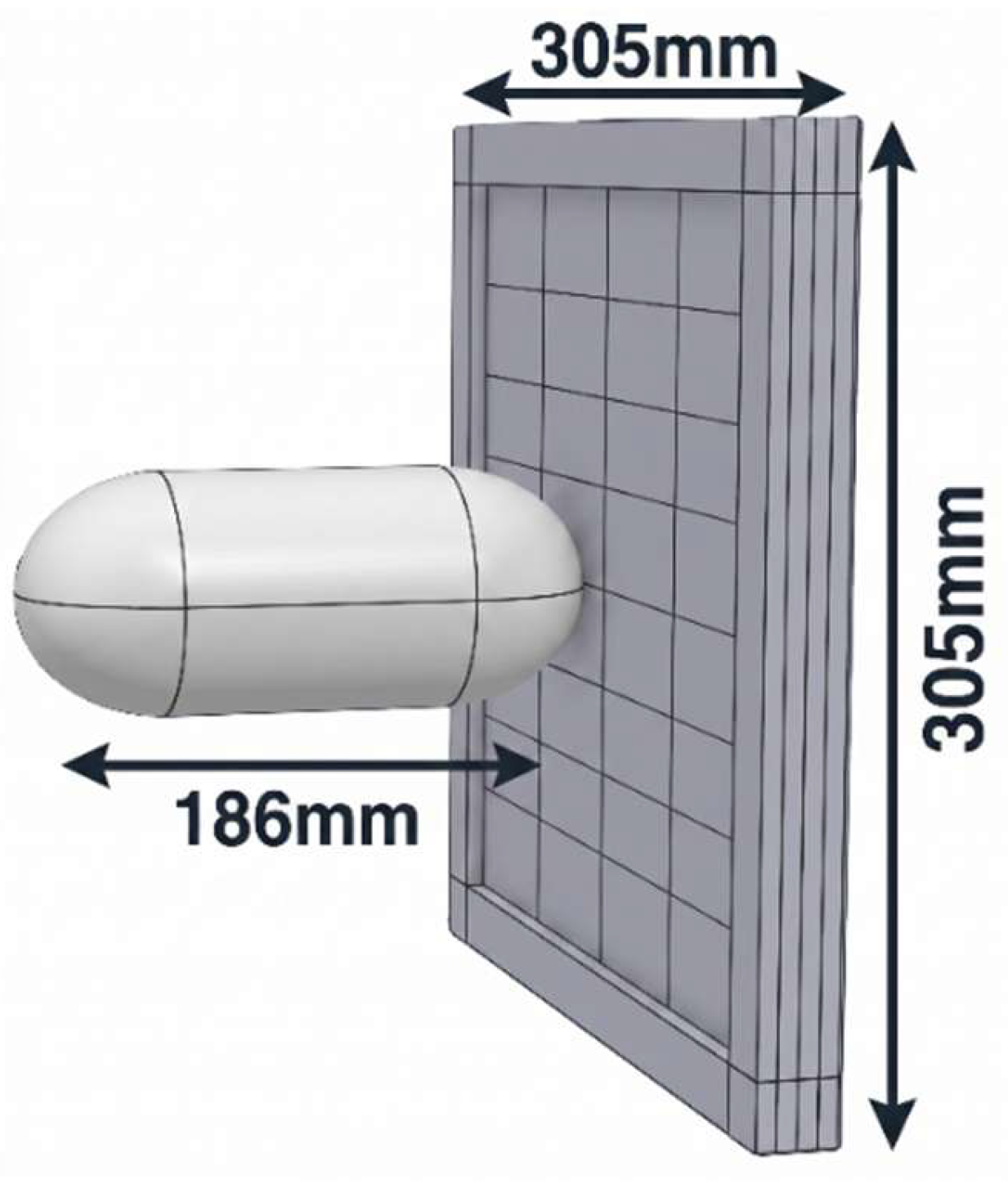
Figure 2.
Numerical and experimental bird deformation behaviour in different time frames.
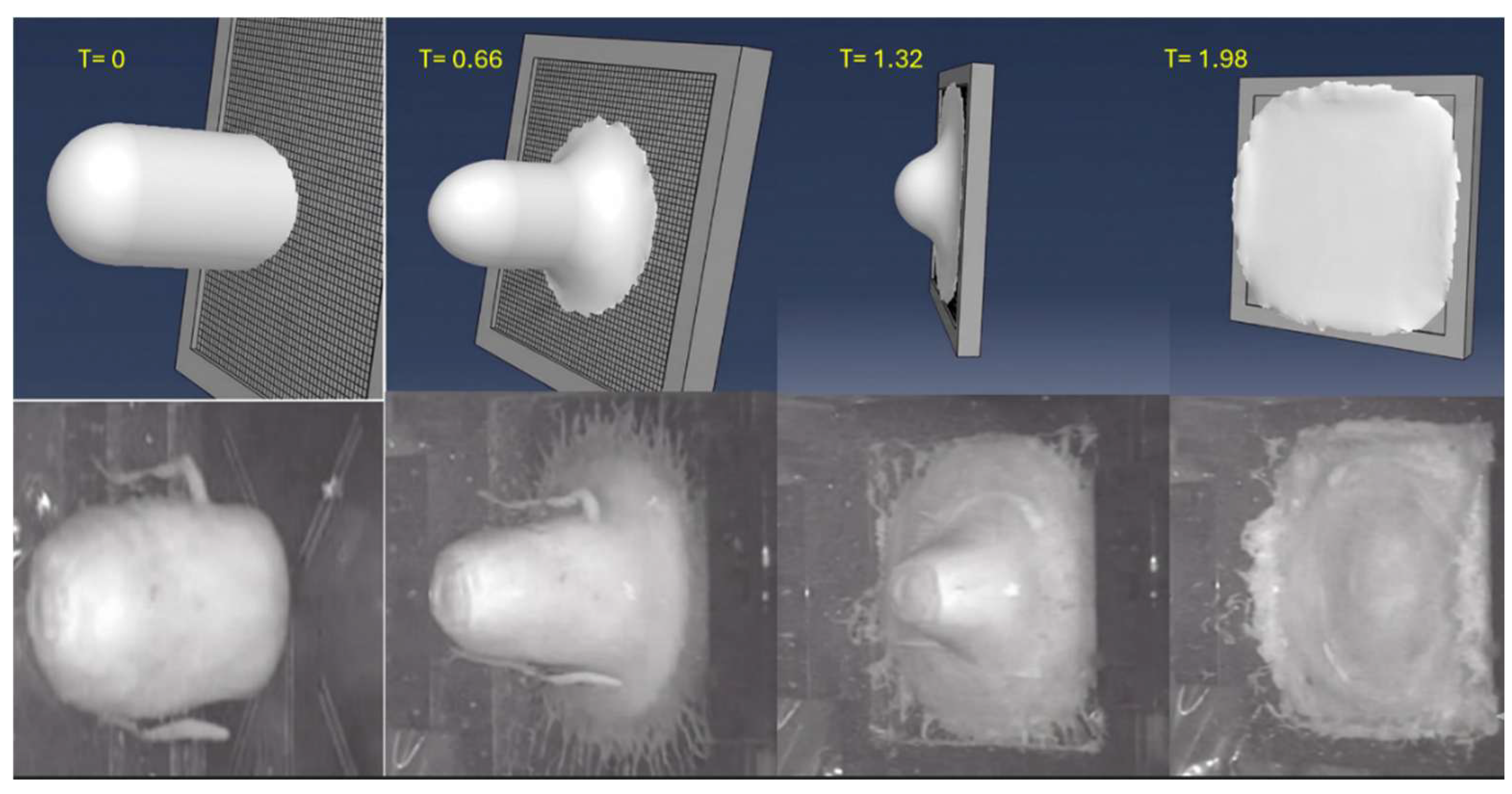
Figure 3.
Validation of the SPH bird model: (a) velocity-time comparison; (b) diameter evolution.
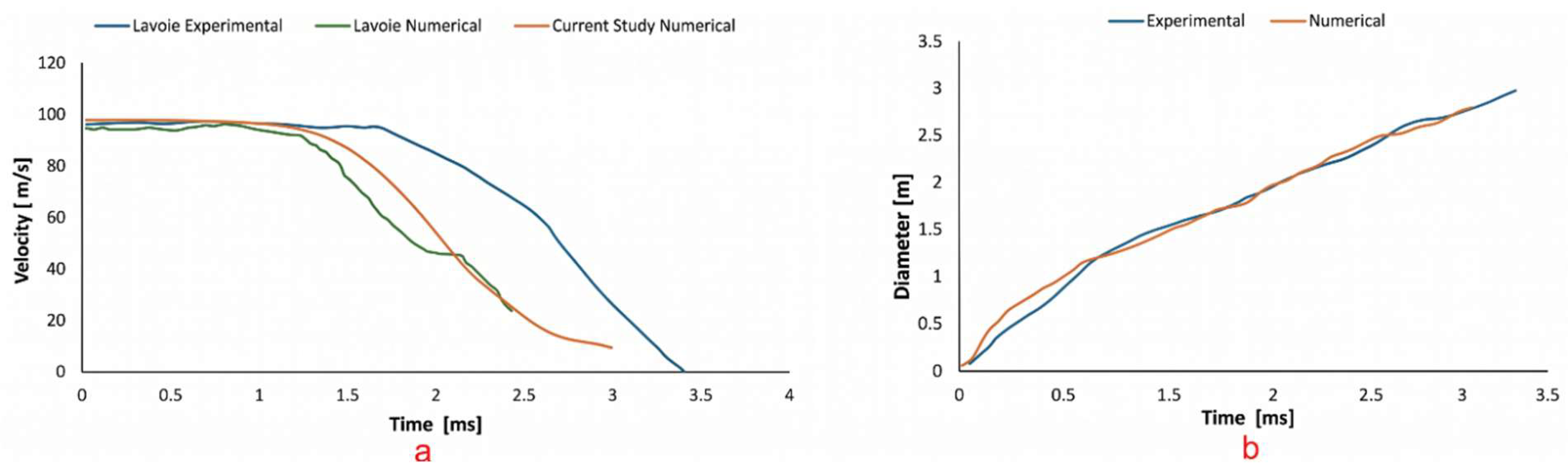
Figure 4.
Initial root section of UAV wing analysed in this study.
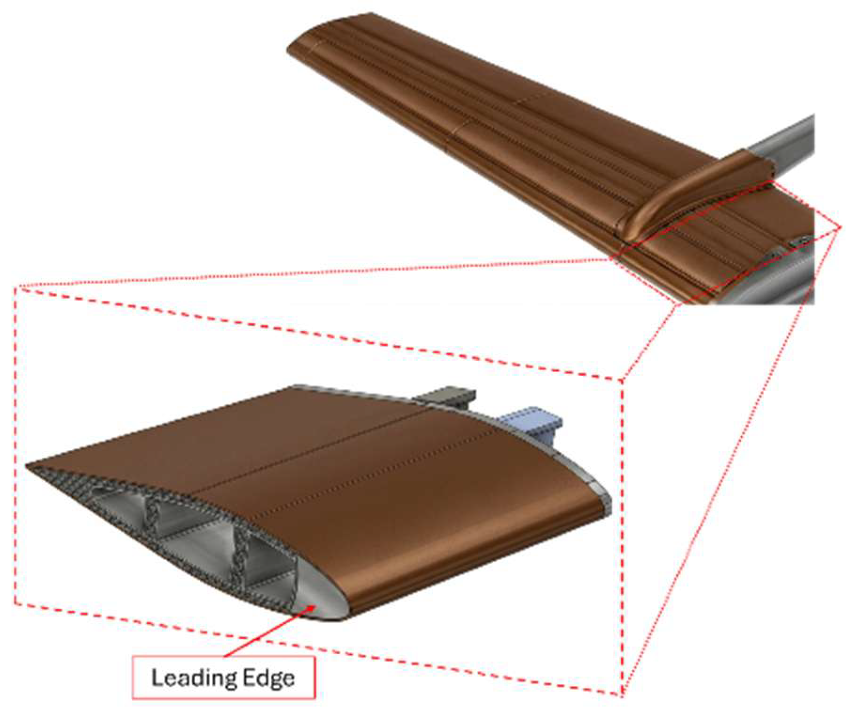
Figure 5.
Overall workflow for lattice generation, parameter definition, and impact analysis.
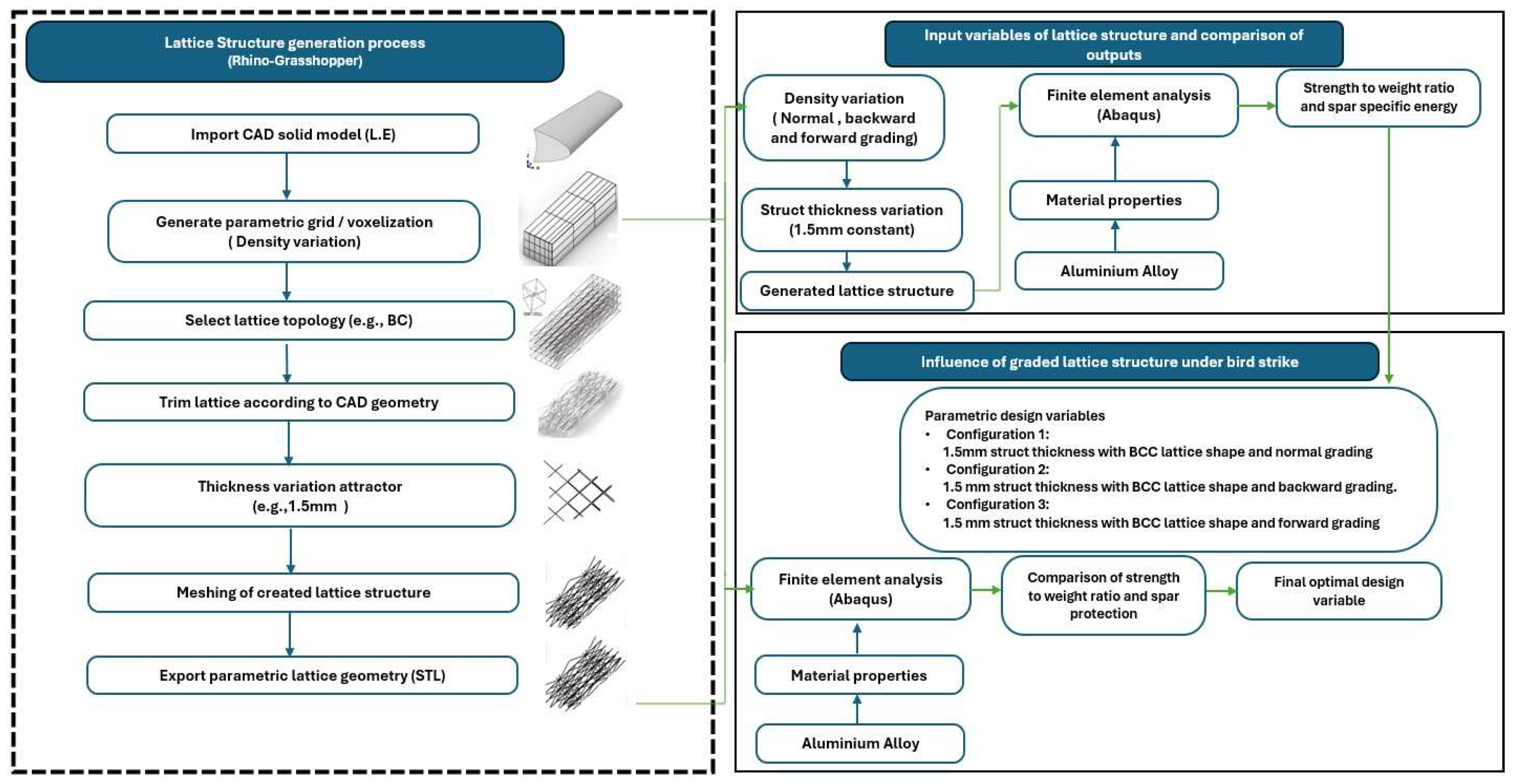
Figure 6.
Grasshopper implementation of lattice density control using Graph Mapper functions: (a) linear mapping for uniform configuration, (b) concave mapping for backward grading, and (c) convex mapping for forward grading.
Figure 6.
Grasshopper implementation of lattice density control using Graph Mapper functions: (a) linear mapping for uniform configuration, (b) concave mapping for backward grading, and (c) convex mapping for forward grading.
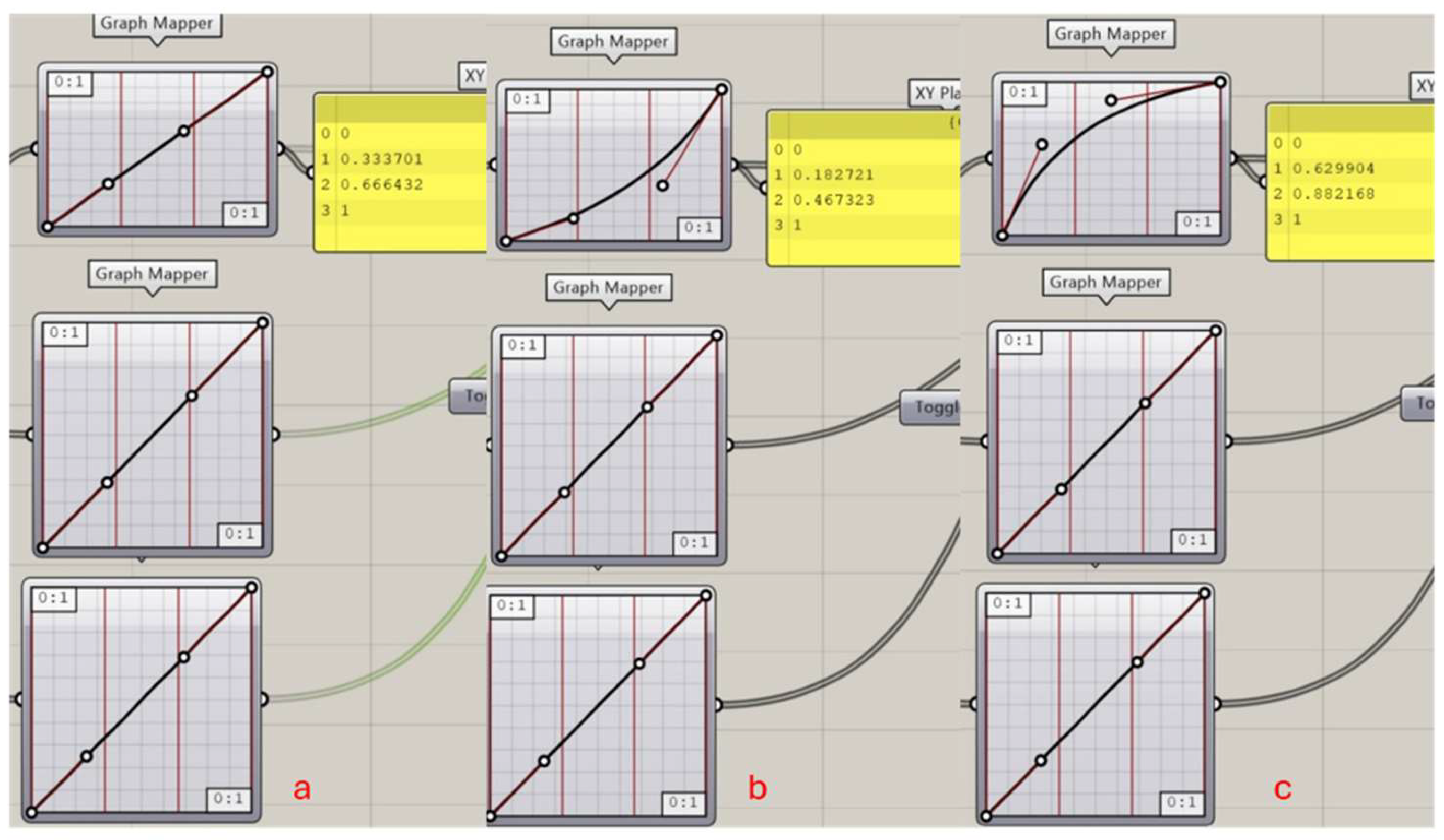
Figure 7.
Solid CAD model of L.E.
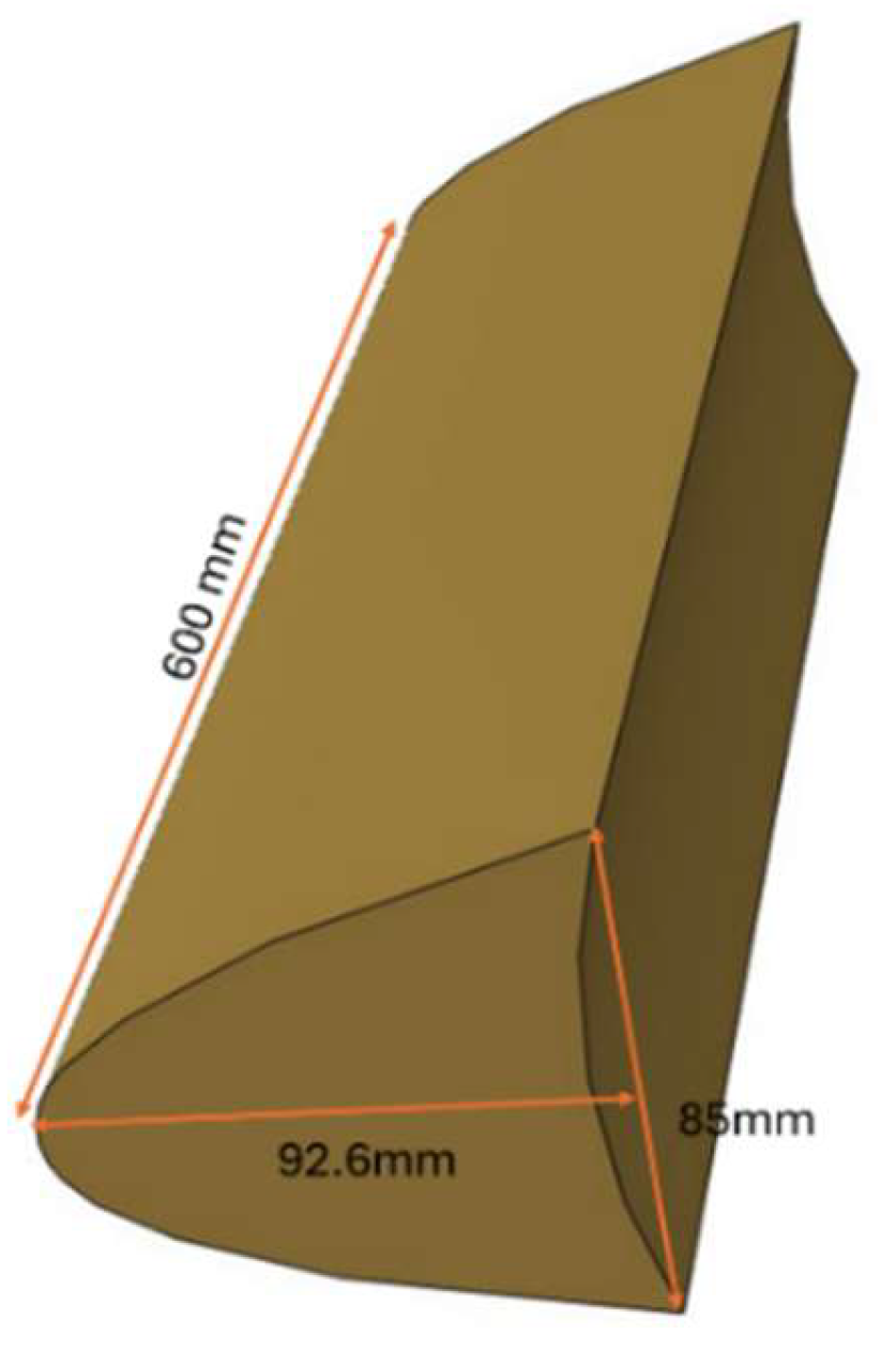
Figure 8.
Side view of the generated BCC lattice structures: (a) uniform lattice, (b) backward graded lattice , and (c) forward graded lattice.
Figure 8.
Side view of the generated BCC lattice structures: (a) uniform lattice, (b) backward graded lattice , and (c) forward graded lattice.
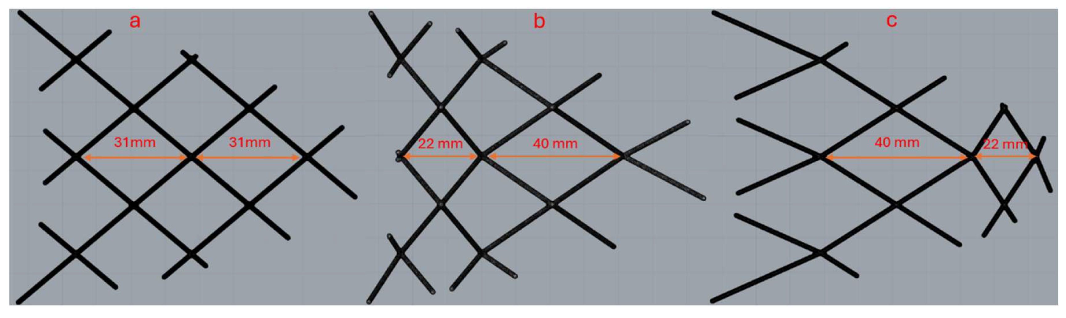
Figure 9.
Wing numerical model used in this analysis.
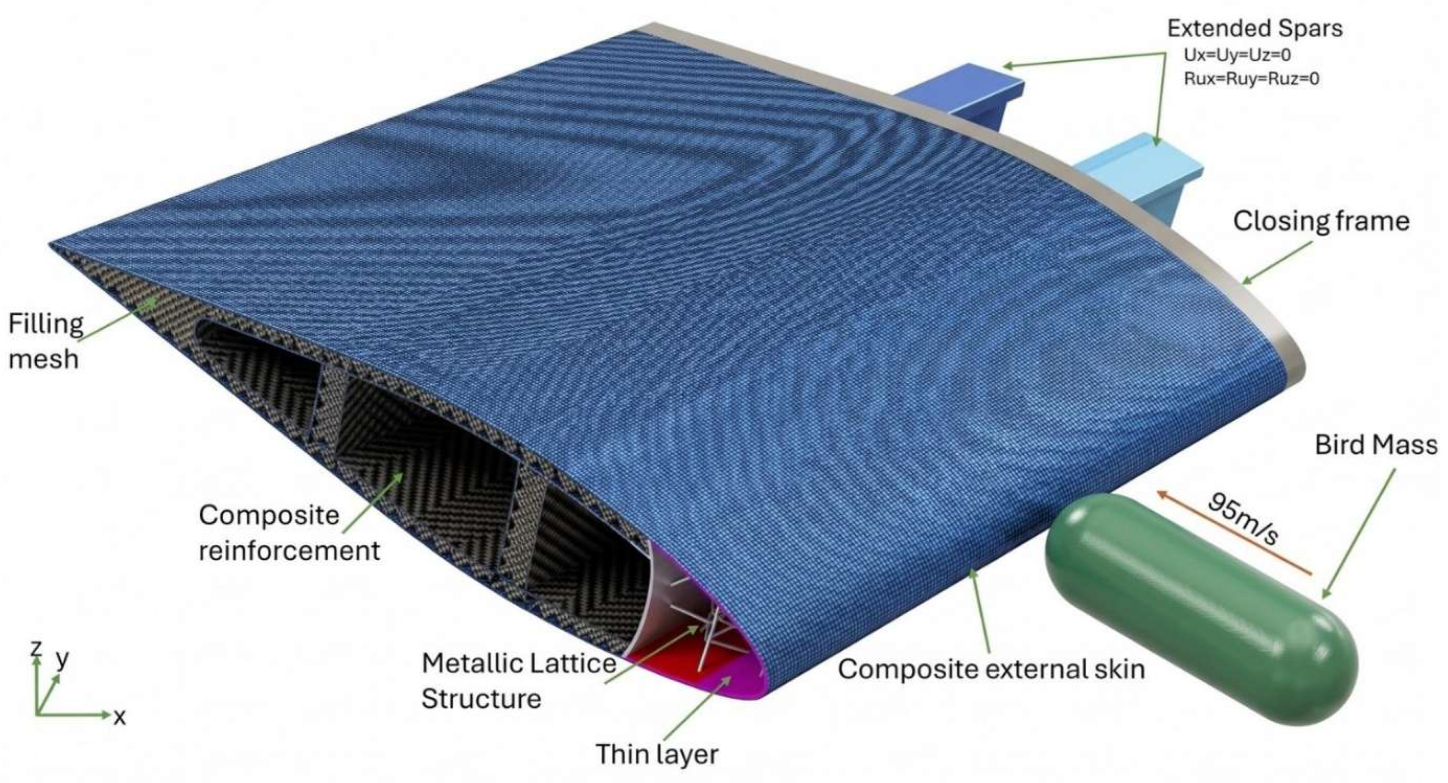
Figure 10.
True stress-plastic strain curve of AlSi10Mg.
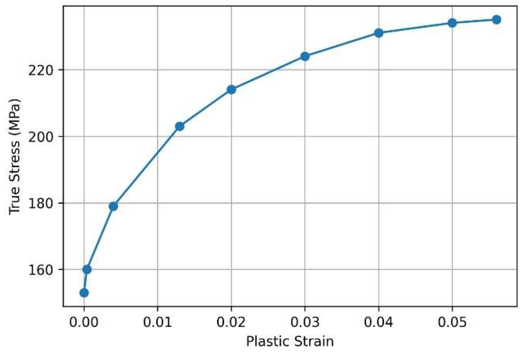
Figure 11.
Stress-strain curve of CF/PA.
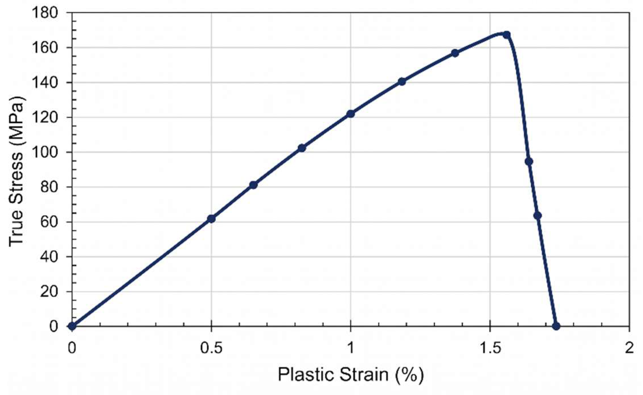
Figure 12.
Mesh convergence of BCC lattice (a) absorb energy, (b) force-displacement.
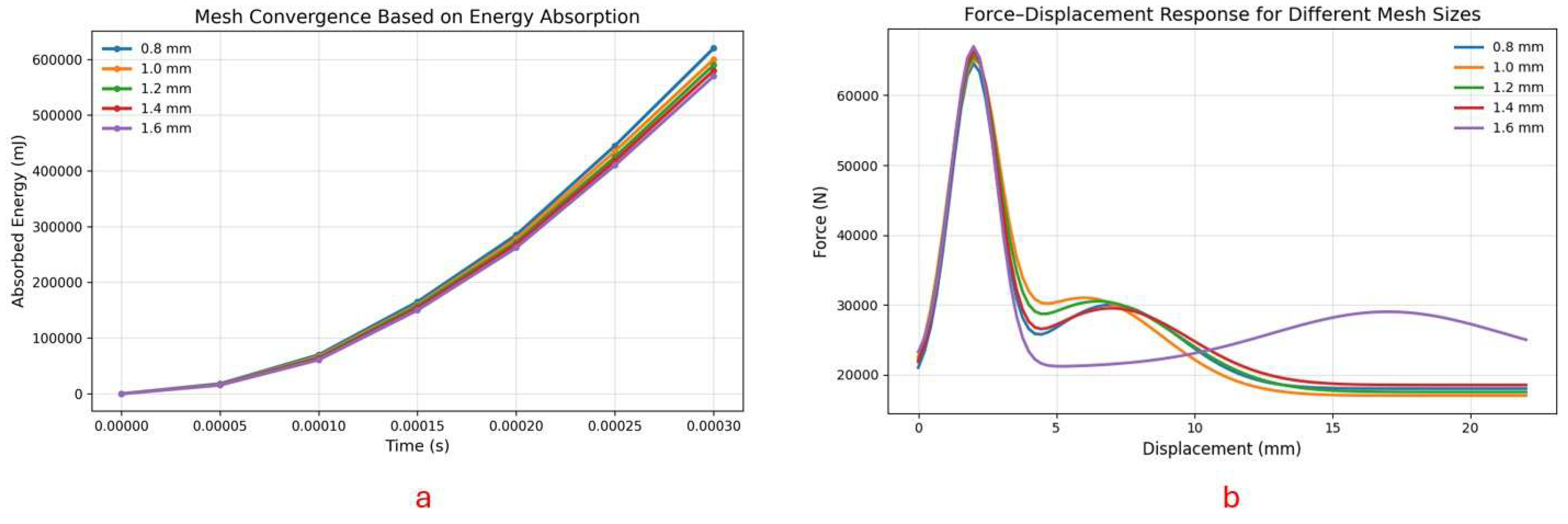
Figure 13.
Post-impact deformation of the L.E for (a) uniform, (b) backward graded, and (c) forward graded lattice configurations. Side and front views illustrate differences in penetration behaviour and damage patterns.
Figure 13.
Post-impact deformation of the L.E for (a) uniform, (b) backward graded, and (c) forward graded lattice configurations. Side and front views illustrate differences in penetration behaviour and damage patterns.
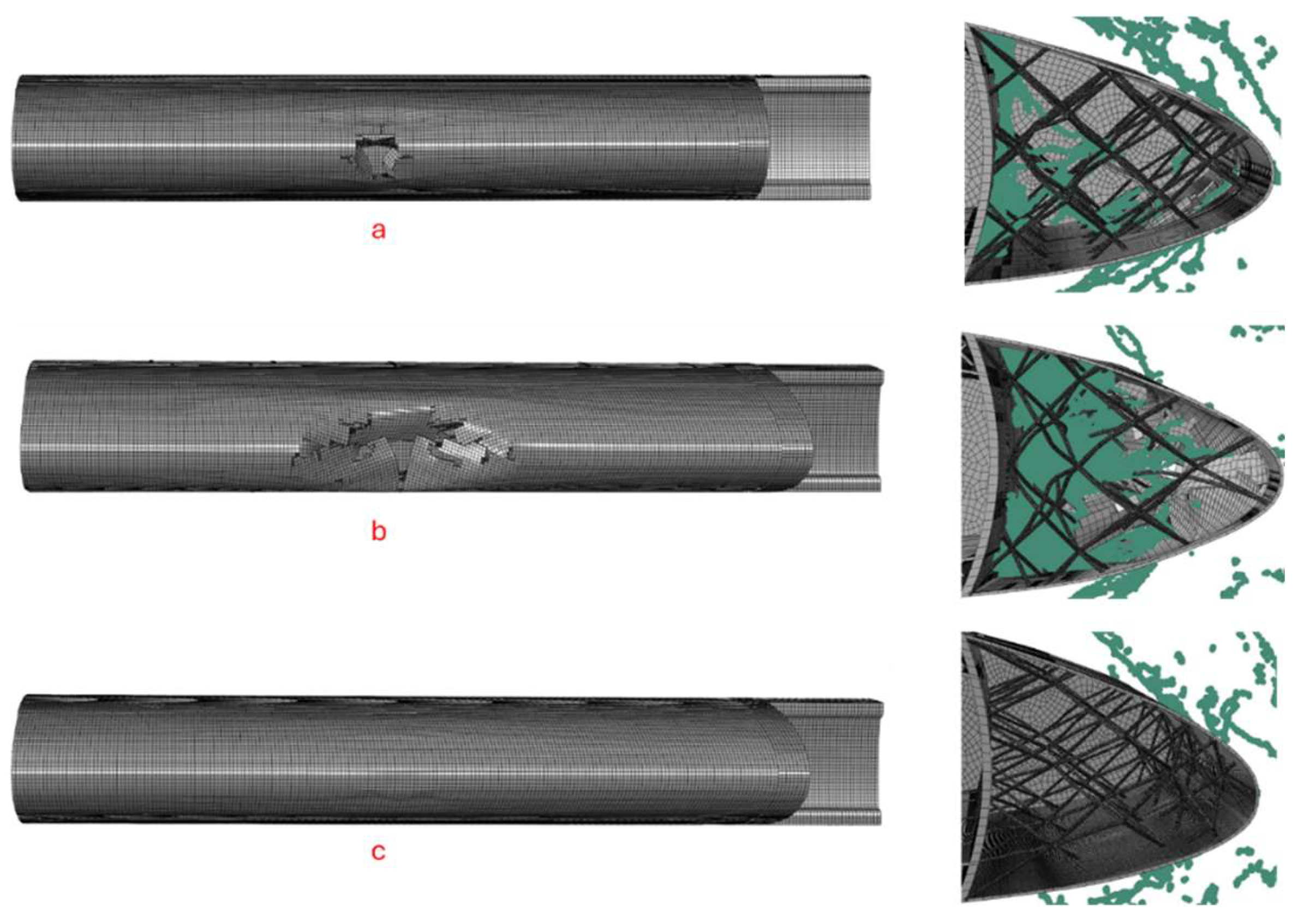
Figure 14.
Maximum displacement comparison for different lattice configurations under bird impact.
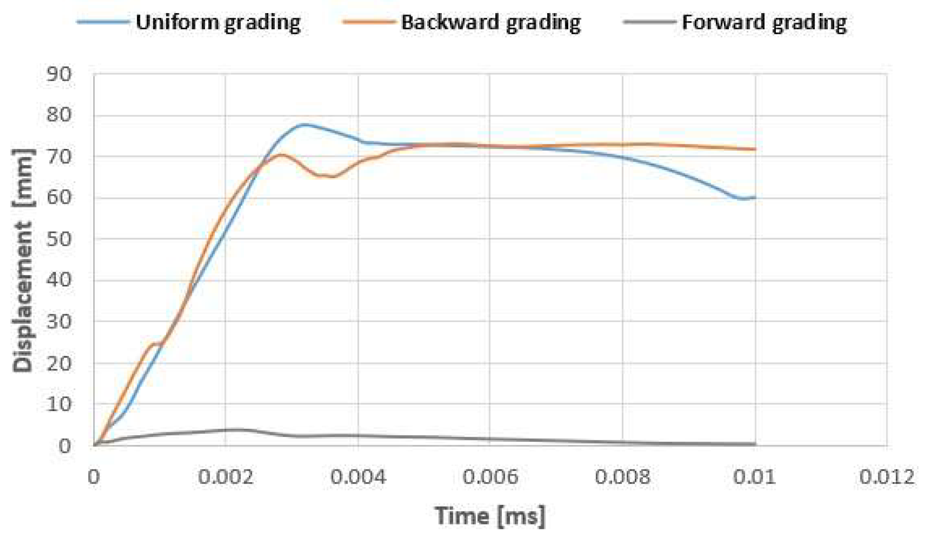
Figure 15.
Displacement response of lattice configurations under bird impact: (a-c) U1 displacement contours for uniform, backward graded, and forward graded configurations, respectively.
Figure 15.
Displacement response of lattice configurations under bird impact: (a-c) U1 displacement contours for uniform, backward graded, and forward graded configurations, respectively.
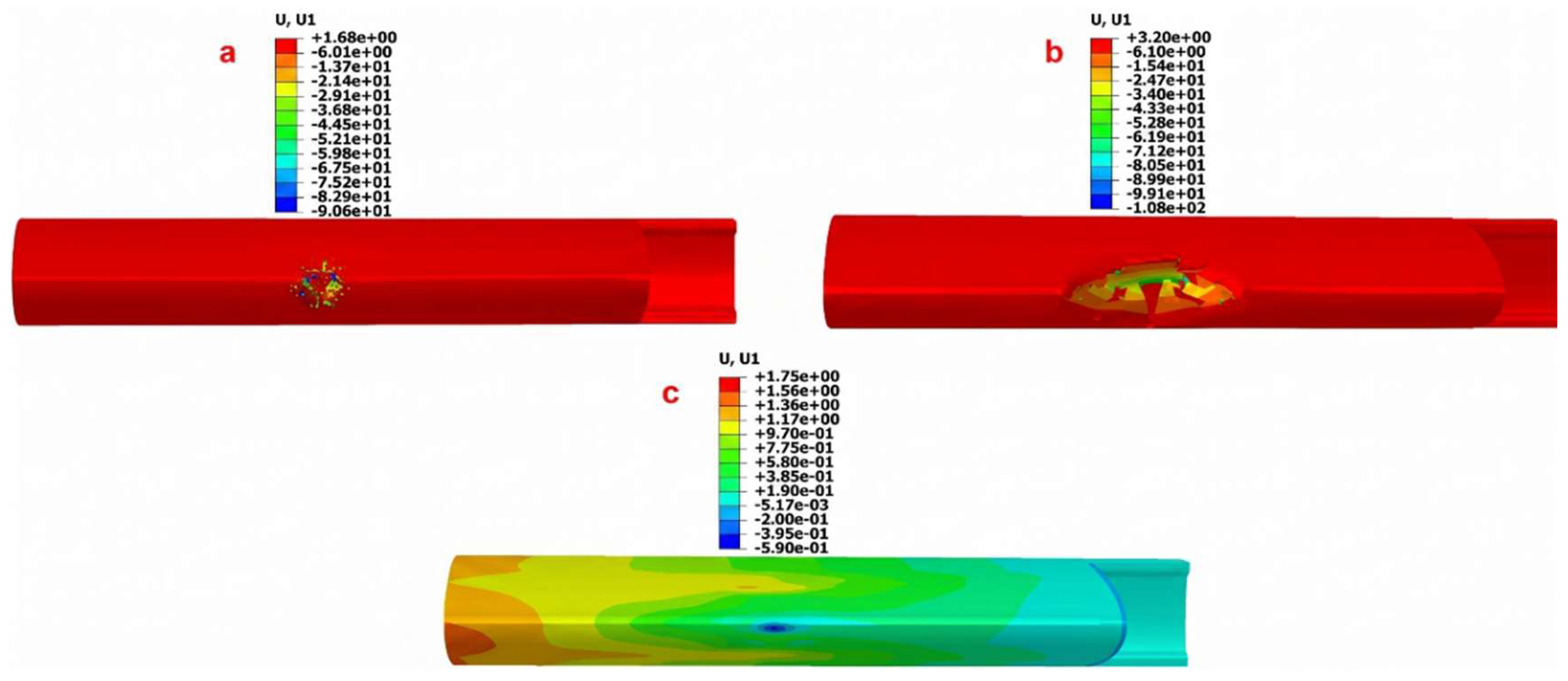
Figure 16.
Equivalent plastic strain (PEEQ) distribution for (a) uniform graded, (b) backward, and (c) forward graded configurations, showing the variation in plastic deformation behaviour.
Figure 16.
Equivalent plastic strain (PEEQ) distribution for (a) uniform graded, (b) backward, and (c) forward graded configurations, showing the variation in plastic deformation behaviour.
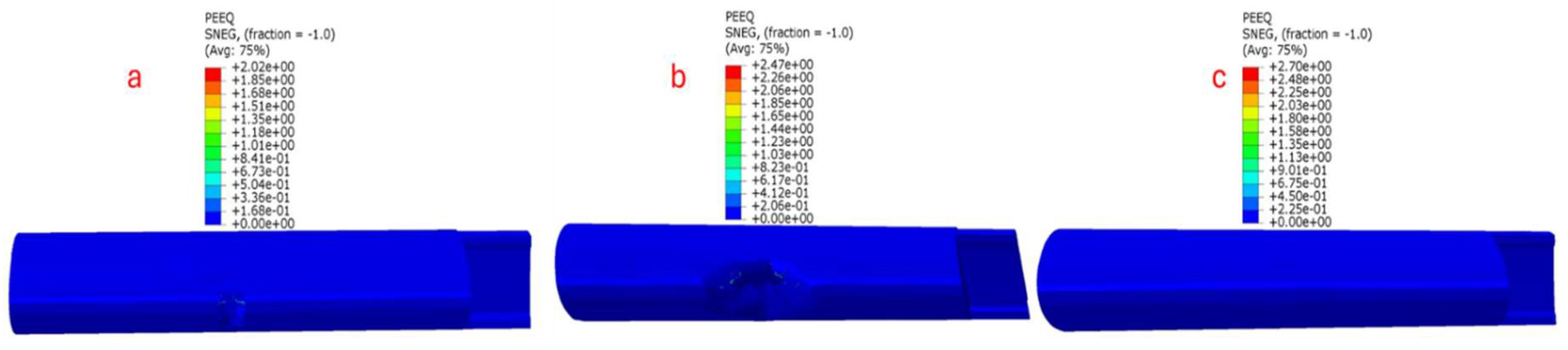
Figure 17.
Ductile damage initiation (DUCTCRT) distribution for (a) Uniform graded, (b) backward, and (c) forward graded configurations.
Figure 17.
Ductile damage initiation (DUCTCRT) distribution for (a) Uniform graded, (b) backward, and (c) forward graded configurations.
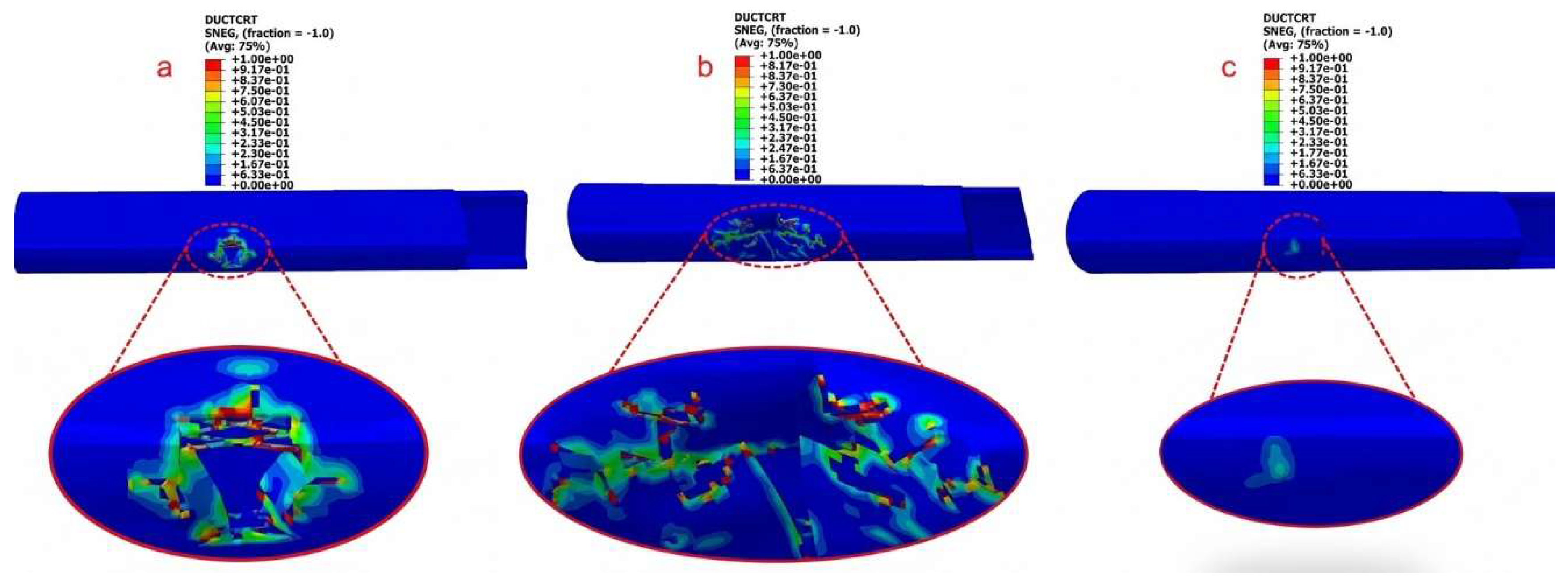
Figure 18.
Energy absorption comparison: (a) lattice energy and (b) spar energy.
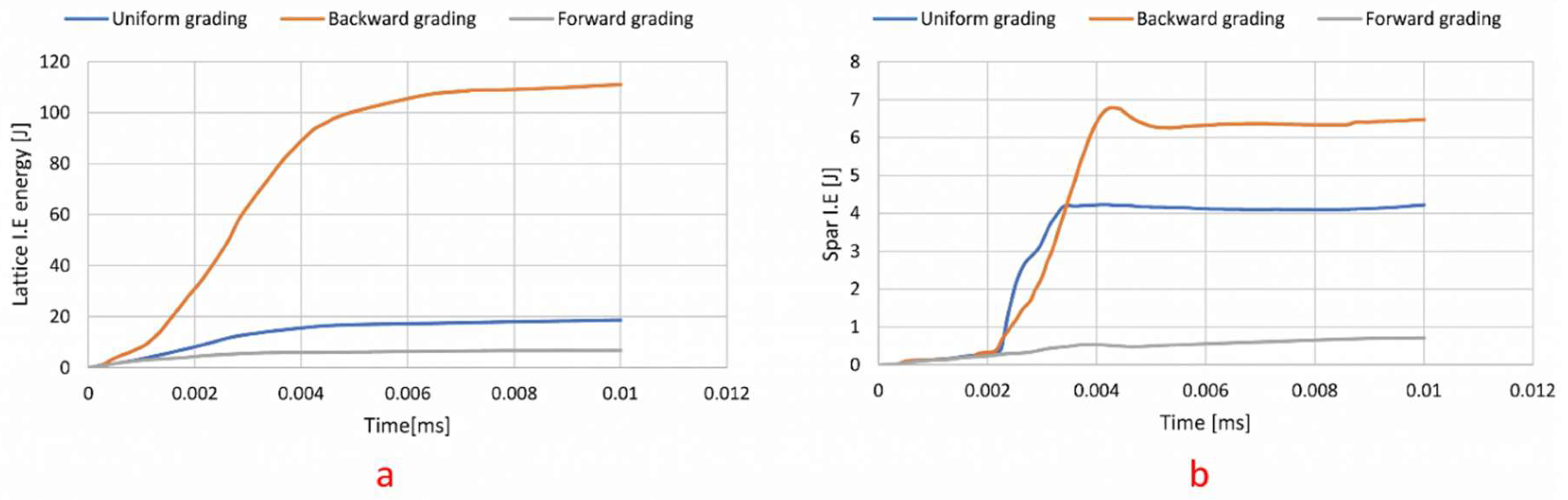
Figure 19.
Von Mises stress distribution for (a) outer composite skin, and (b) lattice structures.
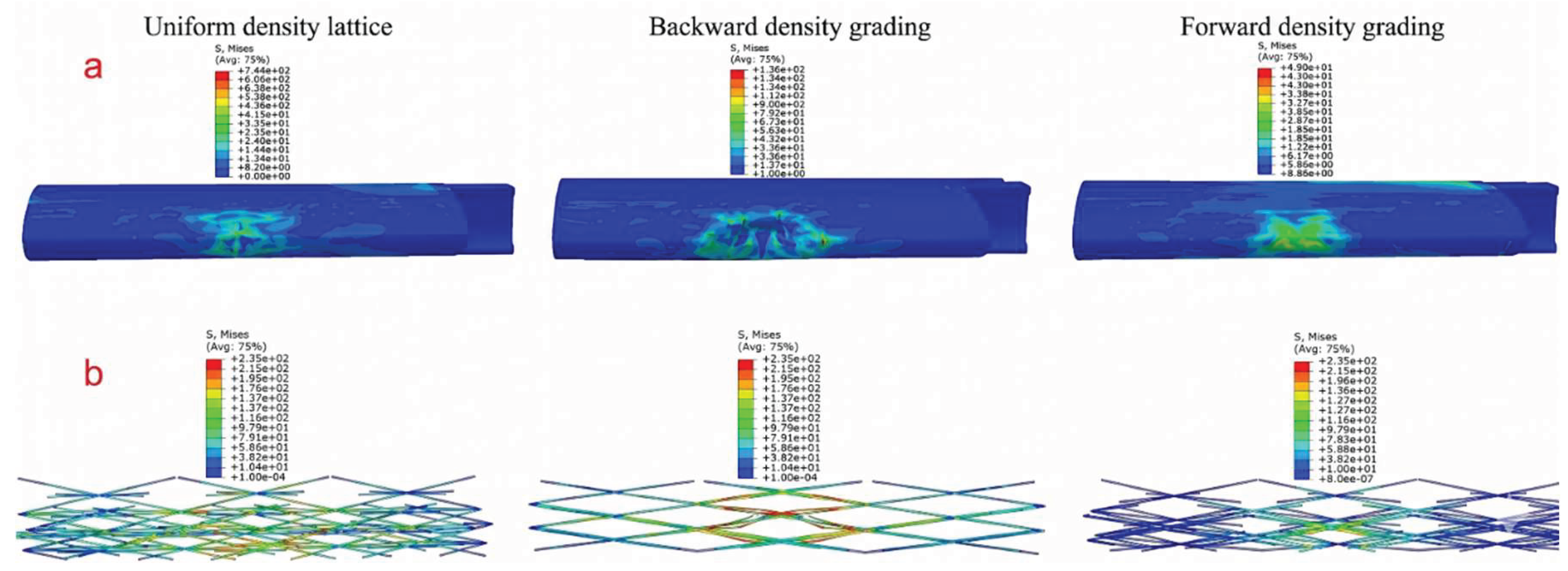

Table 1.
Mechanical Properties of CF/PA and A1Si10Mg.
| Property | Symbol | CF/PA | AlSi10Mg |
|---|---|---|---|
| Density | ρ | 1160 kg/m3 | 2650 kg/m3 |
| Young’s modulus | E | 13.1 GPa | 68 GPa |
| Poisson’s ratio | ν | 0.33 | 0.33 |
| Ultimate tensile strength | σu | 171 MPa | 235 MPa |
| Fracture strain | εf | 0.015 | 0.065 |
| Stress triaxiality | η | -0.33 | 0.33 |
| Fracture energy | Gf | 2.2 kJ/m2 | 67 kJ/m2 |
Table 2.
Comparison of lattice configurations in terms of energy absorption, spar loading, displacement, and mass normalized.
Table 2.
Comparison of lattice configurations in terms of energy absorption, spar loading, displacement, and mass normalized.
| Parameter | Uniform | Backward Graded | Forward Graded |
|---|---|---|---|
| Total structural Mass (kg) | 5.35 | 5.35 | 5.34 |
| Lattice Energy (J) | 18.0 | 110.9 | 6.5 |
| Spar Energy (J) | 4.1 | 6.8 | 0.7 |
| Displacement (mm) | 77 | 73 | 3.8 |
| Specific Lattice Energy (J/Kg) | 3.36 | 20.73 | 1.22 |
| Specific Spar Energy (J/Kg) | 0.56 | 1.20 | 0.13 |
Disclaimer/Publisher’s Note: The statements, opinions and data contained in all publications are solely those of the individual author(s) and contributor(s) and not of MDPI and/or the editor(s). MDPI and/or the editor(s) disclaim responsibility for any injury to people or property resulting from any ideas, methods, instructions or products referred to in the content. |
© 2026 by the authors. Licensee MDPI, Basel, Switzerland. This article is an open access article distributed under the terms and conditions of the Creative Commons Attribution (CC BY) license (http://creativecommons.org/licenses/by/4.0/).
Copyright: This open access article is published under a Creative Commons CC BY 4.0 license, which permit the free download, distribution, and reuse, provided that the author and preprint are cited in any reuse.


