

Submitted:
17 July 2026
Posted:
20 July 2026
You are already at the latest version
Abstract
Polymeric membrane systems have emerged as an effective approach for water separa-tions due to their high separation efficiency, simplicity, and adaptability to a wide range of water treatment applications. However, traditional membrane fabrication processes often rely on toxic organic solvents, such as N-methyl-2-pyrrolidone (NMP) and dime-thylacetamide (DMAc), which pose environmental and health risks. Eco-friendly solvents have been investigated as an alternative to traditional toxic solvents. This study inves-tigates the fabrication and performance of polymeric membranes using eco-friendly solvent systems, with a focus on bilayer membranes designed to improve separation performance over traditional single-layer membranes. Membranes were fabricated using eco-friendly solvents, Rhodiasolv© PolarClean and gamma-valerolactone in combination with polymers polysulfone (PSf) and poly(vinylidene fluoride-co-hexafluoropropylene) (PVDF-HFP). Membranes were fabricated using non-solvent induced phase separation (NIPS) through doctor blade extrusion (DBE) and slot-die coating (SDC) methods in order to compare traditional laboratory-scale casting methods (DBE) with scalable fabrication techniques (SDC). Bilayer membranes were found to overcome the inherent limitations presented by single-layer membranes, such as mechanical stability, with polydopamine (PDA) being incorporated as an adhesion-promoting additive to enhance bonding be-tween polymer layers. Membrane characterization included scanning electron micros-copy (SEM), contact angle measurements, and tensile strength tests, along with per-meability and solute rejection tests to investigate membrane performance. Results showed that membranes fabricated at higher concentrations and through the SDC method per-formed at a higher level than the other membranes, exhibiting improved solute rejection rates and less variability in pore structure distribution.
Keywords:
bilayer membranes
; membrane fabrication
; slot-die coating
; eco-friendly solvents
; scale-up
1. Introduction
Membrane technology has been utilized in liquid and gas separations for decades due to the relative ease in fabrication and operation, high selectivity rates, and absence of sorbent regeneration [1]. Along with their low chemical usage and easy accessibility, membranes can potentially bridge the economical and sustainability gap in a number of fields [2]. In particular, membranes are playing a growing role in desalination, water treatment, and food and pharmaceutical industry applications [2,3,4,5]. In the water treatment sector, membranes are an effective technology for removing pathogenic bacteria, viruses, suspended solids, and other contaminants from drinking water.
The majority of membrane studies have been primarily performed on single polymer membranes, which are referred here as single-layer membranes used to create a porous structure capable of separations [6]. However, despite their widespread use, single-layer membranes are limited in their performance. Since just one material is required to control the selectivity, permeability, and mechanical stability, optimizing one feature may negatively affect the others. Along with the stability of the membrane, the surface is also affected by the limitations of one material. Modifying the surface chemistry of the membrane can influence the hydrophobicity of the membrane and can impact fouling [7]. Changing the surface of the membrane and how it interacts with feed solutions can unintentionally influence permeability or mechanical strength as well. Altering any aspect of the single-layer membrane causes changes in the other aspects, forcing a balance to be found [8]. In order to combat these limitations that the single-layer membranes present, multilayer membranes have been proposed as a next step [9,10]. Specifically, double-layer membranes, or bilayer membranes, have shown promise in combatting these challenges. A bilayer membrane consists of two distinct polymer layers within the membrane, with each one being tailored for a specific final purpose, such as controlling solute rejection, adding mechanical stability, or to influence selectivity mechanisms. Bilayer membranes allow for improved filtration and rejection outcomes, while allowing for optimization of mechanical and structural support since both layers of the bilayer membrane are independently tunable [10,11].
Historically, the development of bilayer membrane technology began with thin-film composite (TFC) membranes, where a thin selective layer of polymer is deposited on top of a porous support layer. These systems demonstrate that separating the selective aspect from the structural function could improve the membrane permeability while maintaining higher solute rejection levels [12]. This has since evolved into polymeric bilayer membranes, where two polymer layers are cast simultaneously to form a single structure. Examples of this are used in seawater desalination, where bilayer membranes with additives, such as silver nanoparticles, are implemented they can operate efficiently by rejecting smaller particles while also surviving harsh conditions such as hard metals and acidic mediums [13]. Bilayer membrane research has explored the use of different polymer combinations to optimize membrane performance. One polymer may be selected for its excellent chemical resistance and selective properties, while another may provide enhanced compatibility with support materials [14,15].
While bilayer membranes offer many advantages to single-layer membranes, their fabrication process introduces additional complications. One issue with bilayer membrane fabrication is ensuring adhesion between polymer layers. If the layers cannot bind effectively during casting and phase inversion, the membrane may experience delamination, where the layers separate when exposed to mechanical stress or during filtration [16]. Delamination can be detrimental to membrane performance and structural integrity. Attaining adequate adhesion between polymer layers depends on a variety of factors, such as polymer compatibility, solvent selection, and the kinetics associated with phase inversion. If the polymers used in the two layers have poor chemical compatibility, or limited intermolecular interactions, there may not be adequate adhesion in the layers. Typically, additives or adhesion-promoting materials, such as polydopamine (PDA) or poly(methyl methacrylate) (PMMA), are implemented to enhance bonding between layers through intermolecular interactions [17,18].
Another challenge in bilayer membrane fabrication lies in controlling the phase inversion process of both polymer layers simultaneously. When the thin film is immersed in the nonsolvent bath during the NIPS process, both layers undergo demixing beginning at the same time at differing rates. However, if there is a large difference in the rate of demixing of each layer, issues such as structural defects, uneven surfaces, or membrane distortion can occur [19].
A final challenge with bilayer membranes lies in its scalability. While laboratory-scale methods such as doctor blade extrusion (DBE) allow for bilayer membranes to be studied under controlled conditions, scaling these techniques to industrial production requires the development of continuous coating methods for multiple layers, introducing complexities in controlling numerous parameters simultaneously. Slot-die coating and roll-to-roll processing are methods that could be used for this, as they are capable of depositing multiple polymer layers at the same time, while maintaining uniform thickness and speeds [20].
In this work, a comparative study was conducted between single-layer and bilayer membranes composed of polysulfone (PSf) and polyvinylidene fluoride-hexafluoropropylene (PVDF-HFP). An additional goal of the comparison study was to fabricate via doctor blade and slot die bilayer membranes with different concentrations of two polymers, using different solvents and additive types for bilayer adhesion. Eco-friendly solvents, Rhodiasolv© PolarClean (PC) and gamma-valerolactone (GVL), were implemented to both single and bilayer membrane fabrication. Characterization of fabricated membranes was performed through investigations of mechanical strength via tensile testing, surface hydrophobicity via water contact angle measurements, and morphology via scanning electron microscopy (SEM) imaging. These characterizations also showed how phase inversion behavior was influenced by dope solution viscosity and polymer concentration.. Finally, rejection studies were performed to determine the relationships between membrane permeability and the rejection of ions and proteins.
2. Materials and Methods
2.1. Selected Materials
The performance of polymeric thin film membranes is strongly influenced by the selection of polymers, solvents, potential additives, and other support materials implemented during fabrication. Selection of these components must be done carefully to ensure the formation of stable casting solutions and favorable phase inversion behavior. Within these experiments, the material selection process emphasized balancing membrane performance, potential for scale-up, and environmental sustainability.
2.1.1. Polymer Selection
Selection of the polymer is crucial for membrane fabrication because the chemical structure and physical properties of the polymer determine the performance and morphological characteristics of the resulting membrane. In this work, Polyvinylidene fluoride-hexafluoropropylene (PVDF-HFP) was obtained from Arkema (Pennsylvania, USA), and polysulfone (PSf, average Mw ~35,000 g mol-1 by LS, Mn ~16,000 g mol-1 by MO, pellets) was purchased from Sigma-Aldrich (St. Louis, MO, USA), were selected as the polymers used in the membrane fabrication processes. Both polymers are widely used in drinking water treatment membranes due to their favorable properties, such as chemical stability and thermal resistance. Even though both polymers are favorable for water separations on their own and can dissolve completely with the selected solvents, combining these polymers for a bilayer membrane introduces complications due to their compatibility. Since PVDF-HFP is a semi-crystalline polymer with low polarity and stronger dispersion forces [21,22], and PSf is an aromatic polymer with strong dipole interactions from the sulfone groups [23], the two polymers have poor miscibility due to their structure differences during bilayer fabrication. The compatibility of the selected polymers with the membrane-forming solvent system was further evaluated using Hansen solubility parameter analysis (Table S.1).
Due to their incompatibility, finding an intermediate adhesion material is necessary to improve bonding between these layers. Previous studies have accomplished layer adhesion using poly(methyl methacrylate) (PMMA) and polydopamine (PDA); however, PMMA has fewer desirable properties for membrane applications due to its hydrophobicity [18]. Along with this, employing PMMA as an additive polymer acts as an intense pore former, creating an unnecessary amount of macro pores, which can weaken the overall mechanical strength of the membrane [11,24]. Previous studies have shown thatPDA enhances layer adhesion but can also increase wrinkling due to its lower crystallinity compared to PMMA. Nevertheless, PDA’s exceptional biocompatibility, biodegradability, and less pore-forming capability makes it a valuable option for membrane adhesion applications [17]. The influence of PDA on the thermodynamic stability and phase separation behavior of the membrane-forming systems was further investigated through ternary phase diagram analysis (Figure S.2).
2.1.2. Solvent Selection
The selection of solvents in membrane fabrication is important in determining the solubility of the selected polymers, the viscosity of the dope solution, and the overall phase inversion behavior. Eco-friendly solvents, such as Rhodiasolv© PolarClean (PC) [25,26] and gamma-valerolactone (GVL) have emerged as sustainable alternatives to more traditional organic solvents in membrane fabrication processes and are used here. The suitability of the PC/GVL solvent system for the selected polymers was assessed using Hansen solubility parameter analysis and relative energy difference (RED) calculations (Table S.1). Furthermore, cloud point measurements were used to evaluate the thermodynamic stability and phase inversion behavior of the polymer–solvent–nonsolvent systems (Figures S.1 and S.2).
2.2. Dope Solution Preparation
Adapting procedures reported by Wei et al. [27], polydopamine (PDA) was prepared by mixing 1% dopamine hydrochloride and 0.5% H2O2 with TrisHCl buffer and DI water at room temperature and a stir rate of 400 rpm for 24 hours.
The preparation of homogeneous polymer casting solutions, or dope solutions, is an important part of the membrane fabrication process. Complete dissolution of the polymer and additives ensures a consistent phase inversion behavior and uniform membrane morphological characterization. For this work, the dope solutions were mixed using a stir plate (VWR) at a constant spin rate of 200 rpm for 24 hours until a dark brown solution was obtained. The visual dark brown color of the dope solutions confirmed the presence of polydopamine. Dope solutions containing PolarClean and GVL were mixed at 80°C. Once fully homogenized, dope solutions were cooled to room temperature before analysis and casting. An Elmasonic P water bath sonicator (Elma Schmidbauer GmbH, Germany) was used to remove residual air bubbles in the solution by sonicating for 15 minutes. The solutions were stored at room temperature and generally lasted for several months. The dope solutions were then fabricated at 17 wt% polymer and 22 wt% polymer for membranes using doctor blade extrusion (DBE), and at 22 wt% polymer for the bilayer membranes using slot-die coating (SDC).
2.3. Casting Process
2.3.1. Single Layer
Single-layer PVDF-HFP and PSf membrane samples were prepared using the doctor blade extrusion (DBE) as described in previous works [28,29,30,31]. In summary, DBE (i.e., blade casting) is a conventionally used method in lab-scale studies to prepare flat sheet membranes involving phase inversion. To prepare membrane sheets using the DBE method, the dope solution was poured onto a glass plate and spread across the plate using a stainless-steel doctor blade (Micrometer Adjustable Film Applicator - 250 mm, MTI Corp, Richmond, CA, USA) set with a coating gap of 0.2 mm. In experiments requiring a membrane cast onto a porous support layer, the support layer sheet was taped onto the glass plate, and solution was cast directly onto the sheet. The casting process then spread the dope solution into a thin film across the plate. The plate was then immersed in a nonsolvent (precipitation) bath containing tap water.
2.3.2. Bilayer
Bilayer casting requires more stability to limit delamination of layers and wrinkling or other defects during the casting process. Unsupported thin film membranes, especially bilayer membranes, can be fragile and have defects due to the lack of support during casting. To prevent this, along with adding additional mechanical strength and improving the integrity of the membrane, a 4” x 8” size sheet of nonwoven fiber (polyethylene) support was taped to a glass substrate.
2.3.2.1. Bilayer Using DBE
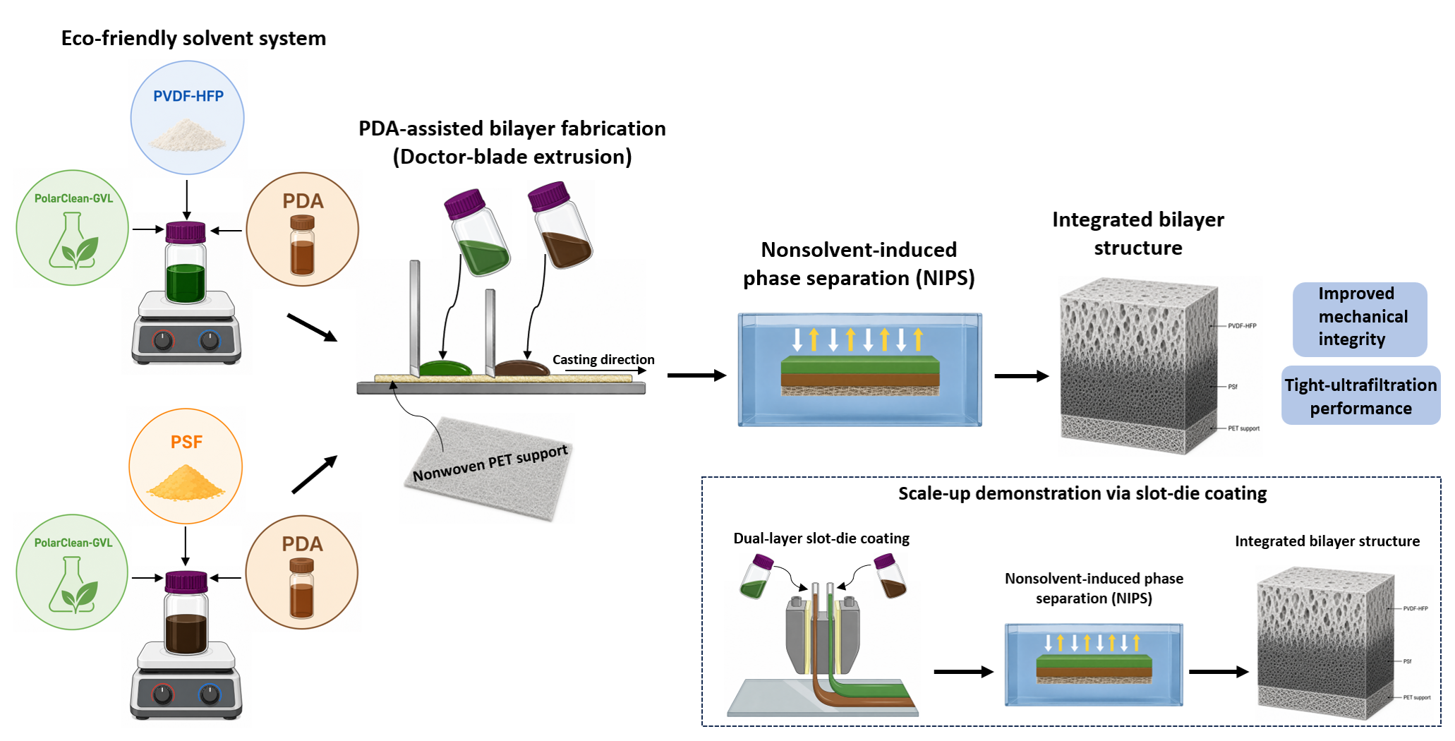
Each dope solution was first extruded using PSf into a thin film (zero gap) on top of the support via doctor blade [31]. Once complete, another extrusion, main first PSf layer, was cast on top of the previous thin layer at 20 micrometers. The casted film and glass substrate were then immersed into a nonsolvent bath of water and allowed to phase invert. After phase inversion occurred, the membranes were stored in a DI water bath for at least 24 hours prior to testing. The fabrication process for bilayer membranes is similar, with the only difference being that two doctor blades and two dope solutions are used during extrusion, as shown in Figure 1. Lined up one after the other, the first doctor blade is set to 20 micrometers and the blade that follows was set to 25 micrometers. The larger setting of the two is the top layer of the bilayer membrane, which contains the PVDF-HFP polymer. The smaller setting is the bottom layer of the membrane, which contains the PSf polymer.
Commercial polymeric membranes are commonly prepared on a porous support layer consisting of woven or nonwoven polyester fabric. This support layer provides the membrane with increased mechanical integrity and is generally significantly more porous in structure [32]. This study investigated the wetting of a nonwoven PET fabric support layer with the dope solution. A Hollytex® 3265 nonwoven fabric was selected due to the durability of PET and its reported effects on the membrane formation [33].
2.3.2.2 Bilayer Using SDC
The dual-layer slot die apparatus comprises two slot die halves along with a central die block. Positioned on each side of the central die block are two PET shims that establish a slot gap of 254 µm for both the bottom and top layers, thus creating two distinct slot gap thicknesses. At the top of the slot die halves, two inlets facilitate the pumping of membrane dope solutions for each layer. These dope solutions are dispensed concurrently onto a moving substrate, which is composed of glass in this study. This method generates a meniscus that coats the substrate, thereby forming a bilayer coating on its surface. A variety of parameters are meticulously controlled throughout this process, including flow rate, coating gap, substrate speed, and shim thickness. In particular, the flow rate, coating gap, and substrate speed are carefully regulated to ensure that the operating conditions remain within the optimal coating window, thereby minimizing the likelihood of defects during the slot die operation [20]. The coating gap and substrate speed were kept constant at 290 µm and 5.4 mm/s, respectively. Following the deposition of the bilayer dope solutions, a phase inversion process is employed, similar to that utilized in the DBE process.
2.4. Membrane Characterization
One characterization technique used to evaluate the mechanical properties of the fabricated membranes was tensile strength testing. This method measures the resistance of a membrane to mechanical deformation and failure under applied stress. Mechanical stability is crucial for membranes since they must be able to withstand pressure-driven filtration, handling, and long-term operational stresses. Using ASTM standard D638-14, membrane samples were cut into dog bone shapes using a mold to ensure uniform testing conditions. Each strip was then mounted into grips of a tensile testing machine, the Instron 3345 Universal Testing Machine (Illinois Tool Works, Norwood, MA, USA) [34].
Hydrophobicity of a membrane refers to the degree of which a surface resists interaction with water. A goniometer was used to analyze membrane wettability and hydrophilicity by measuring the contact angle a water droplet makes with the membrane surface to characterize the membrane as hydrophobic or hydrophilic. In this study, the goniometer used was the Kruss Drop Shape Analyzer DSA1005 (Matthews, NC, USA).
Membrane morphology was evaluated using a scanning Electron Microscopy (SEM) was used to examine the surface morphology of the fabricated membranes. SEM imaging using the Quanta FEG-250 (Thermo Fisher Scientific, Hillsboro, Oregon, USA) provides high-resolution visualization of the membrane features including the pore size distribution and internal pore shape. These are important for understanding the relationship between fabrication conditions and membrane performance.
2.5. Filtration Performance
One of the primary performance measurements taken from the membranes was that of water flux, which describes the passage of the volumetric flow rate of water passing through the membrane per unit of membrane area over time. Flux provides an insight into the permeability of the membrane and its ability to allow water to flow efficiently during a filtration. Flux values were determined by conducting filtration experiments under a controlled pressure of 414 kPa (60 psi). In addition to measuring the permeability of the membranes, solute rejection was evaluated to determine the effectiveness of membranes of separating smaller, dissolved species from water. Table 1 shows the combinations of the tested solutes and their concentration.
3. Results
3.1. Scanning Electron Microscopy (SEM)
Cross sectional SEMs were obtained to observe the microstructure of the bilayer membranes; that is, confirm the PVDF as the membrane top layer, PSf as the membrane bottom layer, and the presence of the support. Furthermore, SEM combined with Energy Dispersive X-ray Spectroscopy (SEM-EDS) was performed to confirm the composition of the membranes by mapping the membrane cross section for fluorine as the identifiable element for PVDF, and sulfur for PSf. It is seen that the PVDF-HFP and PSf layers are in continuous contact, with no gap at the interface, which indicates adhesion between layers. As shown in Figure 2, the SEM-EDS mapping of the bilayer membranes, the presence of fluorine on the surface without any observable presence of sulfur is exhibited (Figure 2(b)). Small streaks of fluorine were observed in the PSf layer and those are likely due to PVDF passing through the membrane pores. Sulfur was present in the layer below the PVDF layer, and as expected due to the casting process, some sulfur seeped through the porous support to fill in the voids of the support (Figure 2(c)). The elemental mapping in Figure 2 confirms the interface between the PVDF-HFP and PSf layers.
No evidence of interfacial delamination was observed in the cross-sectional SEM images (Fig. 2(a), (b), (c)), indicating that the selective and support layers remained well integrated after membrane fabrication. This observation is in agreement with the Hansen solubility analysis (Table S.1), where the PVDF-HFP/PDA/PC/GVL and PSf/PDA/PC/GVL systems exhibited RED values of 0.287 and 0.688, respectively. Since RED values below 1 indicate favorable polymer–solvent compatibility during membrane formation, the calculated compatibility may have contributed to the formation of a continuous interface and the absence of observable interfacial separation.
In addition, SEM was completed on the surface of the membranes to determine their pore structure and uniformity. This information helps explain membrane morphology and can be used to explain trends in membrane performance, such as flux and ion rejection. The surface images of 17 wt% single-layer PSf and PVDF-HFP supported membranes, along with the supported bilayer membrane, are shown in Figure 3.
Due to the hexafluoropropylene (HFP) comonomer in PVDF-HFP, the crystallinity within PVDF is reduced, which reduces the uniformity of the PVDF structure (Figure 3(b)). PVDF on its own is semicrystalline, with both crystalline and amorphous regions [29]. Crystallization in a polymer allows for pore walls to be interconnected within the membrane, and the pores themselves become elongated and less uniform with the addition of HFP. HFP causes a slight delay in the rate of demixing (when compared to PSf), which also contributes to the elongated, less uniform pore structure. Along with this, HFP increases the polymer to become more polar [29].
The surface SEM imagery (Figure 3) results can also be explained when comparing the thermodynamic properties of both PVDF-HFP and PSf membranes. PSf is a completely amorphous polymer, meaning it possesses no crystalline properties [23]. The lack of crystallinity yields a slightly higher rate of demixing (when compared to PVDF-HFP), so the pores are tighter and not elongated like PVDF-HFP membranes. PSf has a slightly lower polymer-solvent affinity when compared to PVDF-HFP, and its polymer-nonsolvent affinity is very low due to the sulfone group found in PSf being polar. When viewing a ternary phase diagram for PSf or a similar substance in polyethersulfone (PES), the binodal curve is closer to the polymer-solvent axis, and the spinodal curve is close to the binodal curve [35]. This yields a smaller metastable region, which means there is a higher rate of demixing. This higher rate of demixing causes the phase inversion time during NIPS to be quicker leading to a more uniform pore structure.
PVDF-HFP, on the other hand, possesses higher polymer-solvent affinity along with a low polymer-nonsolvent affinity. When viewing a ternary phase diagram, the binodal curve is closer to the nonsolvent axis, which indicates a slight delay before the phase separation occurs during NIPS. The spinodal curve is pushed farther inward on the diagram, leading to a larger metastable region. When the metastable region is larger, there is a delayed rate of demixing. The phase inversion time with PVDF-HFP membranes is slower [36] than PSf membranes because of this, leading to an elongated pore structure [37]. The bilayer membrane surface morphology (Figure 3(c)) is similar to that of the PVDF-HFP single-layer membrane due to the PSf layer being the top layer of the bilayer. There is more blockage of pores in the bilayer membrane, with polydopamine appearing as a bright circular shape within the pore structure. The polydopamine becoming trapped within the pores more in the bilayer membrane versus the single layer counterparts implies that the bilayer membrane will reject more filtrate when rejection studies are completed.
3.2. Young’s Modulus
Mechanical testing, using Young’s Modulus, of the membrane samples was completed to investigate the effects of polyethylene support and polymer selection. The mechanical strength differences between single-layer and bilayer membranes were investigated as well. A higher Young’s Modulus means the membrane resists stretching and deformation, and a lower Young’s Modulus value is more susceptible to stretching and deformation. Membranes with a higher Young’s Modulus are more durable than those with lower Young’s Modulus but can be too stiff to the point where brittleness and cracks can appear [38]. As previously stated, in order to improve the Young’s Modulus of all membrane types, the membranes were cast on the polyethylene nonwoven support [31]. A comparison of Young’s Modulus across polymer types and a comparison of single layer and bilayer eco-friendly membranes is shown in Table 2.
Table 2 depicts the results of the Young’s Modulus tests completed on supported eco-friendly single and bilayer membranes. Polysulfone (PSf) single-layer membranes yield a higher Young’s Modulus than PVDF-HFP single-layer membranes. This is likely due to the stability and rigidity of PSf, as a result of aromatic content and strong intermolecular forces in its polymer chains. Sulfonyl groups (SO2) within the PSf lead to increased electronegativity and polarity, which may also contribute to the increased strength of PSf membranes [28,31]. PVDF-HFP is known to be semicrystalline, with even lower crystallinity than PVDF due to HFP comonomers interfering with the formation of ordered crystalline packing regions [39]. This instability disrupts the order and stiffness of the PVDF-HFP membranes and allows for a more flexible and stretchable membrane[40]. When comparing single-layer and bilayer membranes, the bilayer membranes were found to have a higher Young’s Modulus, which is likely due to the additional layer providing increased mechanical strength to the overall membrane.
3.3. Hydrophobicity
Hydrophobicity, shown in Figure 4, is approximately the same across all membrane types, including those of both single and bilayer membranes. There was no statistically significant difference when comparing these membranes, and all are found to be minimally hydrophobic. The similarities in hydrophobicity values can be attributed to both PVDF-HFP and PSf being hydrophobic polymers. PVDF-HFP possesses higher fluorine content in the form of highly non-polarizable C-F bonds, which repel water molecules. PSf contains aromatic rings and sulfone groups, which hinder hydrogen bonding with molecules. Along with this, polymer concentration does not affect the hydrophobicity of membranes.
3.4. Membrane Permselectivity
3.4.1. Water Flux
To assess membrane performance and to evaluate the permeability, filtration experiments were performed on the nine types of membranes fabricated here. Three membranes consisted of 17 wt% polymer and were fabricated using the DBE method: one being polysulfone, one being PVDF-HFP, and the third being a bilayer, all in triplicates. As previously stated, the top layer of the bilayer membrane contained PVDF-HFP, while the bottom layer of the membrane was PSf. Another set of membranes were 22 wt% polymer which were also fabricated using the DBE method: one being polysulfone, one being PVDF-HFP, and the third being a bilayer. Finally, the last set of three membranes was fabricated using the SDC method and were all bilayer membranes. These membranes were fabricated similarly, but the top PVDF-HFP layer of the membrane had differing flow rates onto the substrate during the SDC method to assess the influence of flow rate on the results. The first SDC bilayer membrane, referred to SDC Bilayer 1, had a flowrate of 0.86 mL/min of PVDF-HFP dope solution. The second SDC bilayer membrane, referred to as SDC Bilayer 2 in the following figures, had a flowrate of 0.72 mL/min of PVDF-HFP dope solution. Finally, the last SDC bilayer membrane, referred to as SDC Bilayer 3 in the following figures, had a flowrate of 0.61 mL/min of PVDF-HFP dope solution during the casting process. The water flux of each membrane in liters per square meter per hour (LMH) is shown in Figure 5.
The DBE 17 wt% membranes have a larger flux than the DBE 22 wt% membranes and SDC membranes, as illustrated in Figure 5, showing that lower polymer concentrations have an impact on the overall permeability of the membrane. When comparing the SDC membranes to the DBE 22 wt% membranes, the flux values become closer in value, with the SDC membranes showing slightly lower flux values, indicating lower permeability.
When solutions are fabricated at lower polymer concentrations, the dope solution contains more solvent than solutions with higher polymer concentrations. This reduces the viscosity of the solution. During the NIPS process, the lower viscosity of the solution leads to more rapid solvent-nonsolvent exchange, leading to instantaneous demixing at the interface of the membrane. When the rate of demixing is high, large macrovoids and heterogenous pore structures are likely to form within the membrane [41,42]. The variability in permeability lies in the large macrovoids (Figure 3), leading to a more variable water transport when passed through the membrane. Studies have shown that membranes fabricated at lower polymer concentrations have increased structural regularities and varying pore size distribution, which contributes to the larger standard deviation in water flux values [43,44]. This is supported by SEM images of the surfaces of various membranes, shown in Figure 3. In contrast, higher viscosity dope solutions lead to a slower diffusion of solvent and nonsolvent molecules during the NIPS process, leading to more controlled demixing, which limits the formation of macrovoid structures [41,42]. The resulting membrane will have smaller, more uniformly distributed pores. This leads to more consistent water transport through the membrane, decreasing the variability in the water flux values.
When comparing the different polymers, PSf membranes typically have a smaller standard deviation in the water flux than PVDF-HFP membranes. PSf is known to have strong interactions with many polar solvents, like PolarClean and GVL, allowing the phase inversion process to be more stable [26]. However, the PVDF-HFP membranes, primarily the DBE 22 wt% PVDF-HFP membranes, exhibit larger standard deviation values. Since PVDF-HFP is a semicrystalline, fluoropolymer that has lower crystallinity than PVDF, it has a weaker polymer-nonsolvent affinity and stronger polymer-solvent affinity. The higher affinity for the solvent of the polymer rather than the nonsolvent leads to delayed demixing, which results in the stretched pore shape as shown in the SEM images [22,41]. These open pores increased the permeability of the membrane but also introduces variability in the pore geometry and internal structure. This leads to higher flux values, but the standard deviation will also be high due to the varying transport pathways within the membrane.
The DBE 22 wt% bilayer membranes displayed the lowest permeability values and standard deviations when compared to the DBE single-layer membranes. The interaction between the two layers is hypothesized to help stabilize the membrane morphology during the phase inversion process, which can reduce the irregularities seen in single-layer systems, such as macrovoid formation or stretched pores. This leads to a more uniform pore distribution and shape, which provides more consistent permeability and lower standard deviation in water flux.
Finally, the SDC membranes demonstrated the lowest permeability values and associated standard deviations within all the membranes tested. This can be directly attributed to the greater precision and control that the SDC method provides compared to the traditional DBE method. SDC enables high levels of control over the dope solution deposition, producing films with uniform thickness and coating speeds. These factors contribute to the solvent-nonsolvent exchange during NIPS to occur more uniformly, resulting in a more homogenous pore structure across the membrane structure, lowering the standard deviation associated with the water flux of these membranes [41]. The DBE method may unintentionally introduce small fluctuations in film thickness through difficult to control parameters such as blade position, casting speed, or solution distribution.
3.4.2. Solute Rejection
To evaluate membrane performance and compare the pore formation between membranes, ion rejection experiments were completed across supported single and bilayer membranes. Initially, sodium chloride was selected as feed solution to simulate reverse osmosis behavior to determine if the membranes tested here were able to achieve monovalent ion rejection. Sodium chloride possesses monovalent sodium ions that have hydrodynamic radii of 3.6 Angstroms (~0.36 nm) and 4-6 water molecules hydration number [45]. Sodium chloride solutions at 100 ppm were filtered through each membrane type, and a conductivity meter was used to assess how sodium ion rejection. All rejection values for all single and bilayer membranes with both SDC and DBE methods were below 10%, with most nearing no rejection. This shows that the pore sizes of the membranes were larger than the hydrodynamic radius of sodium molecules, and thus even the bilayer membranes could not emulate reverse osmosis behavior. Filtrations were followed with divalent ions and BSA protein. Results are shown in Figure 6.
Since monovalent ions were not filtered by the membranes, similar experiments were performed using divalent ions in the form of calcium chloride to determine if the bilayer membranes could simulate nanofiltration behavior. Divalent ions have hydrodynamic radii of 4.1 Angstroms (~0.41 nm) and 6-8 water molecules hydration number [46]. Divalent cations in the form of CaCl2 at a concentration of 100 ppm were filtered through the membranes, and results are shown in Figure 6. It can be observed from the figure that when divalent ions were filtered, the bilayer DBE membranes (both 17 wt% and 22 wt%) displayed increased rejections, approximately 65% and over 70%, respectively, when compared to their single layer counterparts, all below 65%. This result partially coincides with the SDC fabricated bilayer membrane, where dual-layer phase inversion creates a thick skin layer due to additional delayed mixing due to an additional polymeric membrane on top. Outside of the DBE 22% bilayer membrane, the SDC membranes were able to reject divalent ions at the highest rate, approximately 63 to 68%. The rejection percentage increased with decreasing PVDF-HFP layer flux rate. This trend is consistent with theory, where the higher flux rate in the PVDF-HFP layer indicates higher permeability and lower rejection.
To evaluate membrane performance and compare pore formation between membranes fabricated with varying polymer concentrations and methods, rejection experiments using bovine serum albumin (BSA) were performed. BSA is a globular protein derived from cow blood that is commonly used a model macromolecule in membrane filtration studies. It is larger than monovalent and divalent ions, measured to be approximately 69 kilodaltons [47]. The BSA rejection results of the same nine membranes fabricated using DBE and SDC methods, are shown in Figure 6.
The bilayer membranes fabricated using SDC exhibited the highest BSA rejection are also shown in Figure 6. SDC Bilayer 3 demonstrated the highest rejection, with values around 97%, followed by SDC Bilayer 2, then SDC Bilayer 1. When comparing the SDC membranes, this follows the trends set by the results of water flux of these membranes. SDC Bilayer 3 had the lowest water flux, but the highest BSA rejection of the three SDC membranes. Importantly, the SDC membranes have lower standard deviation, likely due to the more automated casting process versus the more manual DBE approach. DBE membranes showed lower rejection as compared to SDC membranes. Specifically, the DBE 17 wt% single-layer (polysulfone and PVDF-HFP) membranes exhibited the lowest rejection, around 85-86%. The DBE 17 wt% bilayer membrane was able to reach rejection levels of almost 89%. This was higher than that of the DBE 22 wt% single layer membranes, but not as high as the 92% rejection of the DBE 22 wt% bilayer membrane. Both DBE bilayer membranes exhibited higher rejections than their single layer counterparts, and the higher polymer concentration did lead to an improvement in the rejection of BSA. The selective layer of the bilayer structure likely contributed to improved control over pore size and solute transport through the membrane, as observed by SEM images shown in Figure 3. SDC membranes showing consistently higher rejection suggests that the slot die provides more precise control over features leading to consistent rejection, such as layer uniformity, during casting.
4. Conclusions
The primary objective of this work was to investigate the fabrication and performance of eco-friendly polymeric membranes for water treatment applications, with a focus on developing eco-friendly bilayer membranes. Single-layer and bilayer membranes were successfully fabricated using eco-friendly solvents, demonstrating that sustainable alternatives can effectively replace more traditional, toxic options. Using Hansen solubility parameters, compatibility between polymers and solvents could be found. A comparative analysis of two casting techniques based on Non-Solvent Induced Phase Separation (NIPS), doctor blade extrusion (DBE) and slot-die coating (SDC), highlighted the differences in membrane fabrication and performance. Polydopamine was used to promote adhesion between the two membrane layers. Performance testing showed solute rejection in the tight ultrafiltration range, with a divalent rejection rate ranging from 52 to 73% and BSA rejection rate ranging from 85-97%. Overall, this work shows that eco-friendly solvent systems can be successfully implemented in polymeric membrane fabrication, with bilayer systems providing an effective strategy for improving membrane performance. These results highlight the importance of controlling parameters such as polymer concentration and polymer-solvent interaction during the fabrication process to develop effective eco-friendly membrane technologies for water treatment.
Supplementary Materials
The following supporting information can be downloaded at the website of this paper posted on Preprints.org.
Author Contributions
Conceptualization, I.C.E and T.A.L.H.; methodology, I.C.E. and T.A.L.H.; investigation, E.K.; data curation, E.K., M.J., T.S. and M.U.Y.; writing—original draft preparation, E.K. and I.C.E.; writing—review and editing, I.C.E., T.S., M.U.Y. and T.A.L.H.; funding acquisition, I.C.E and T.A.L.H. All authors have read and agreed to the published version of the manuscript.
Funding
This research was funded by National Science Foundation under Grant Numbers 2121674 and 1922694.
Data Availability Statement
The raw data supporting the conclusions of this article will be made available by the authors on request.
Conflicts of Interest
The authors declare no conflicts of interest.
References
- Pendergast, M.M.; Hoek, E.M.V. A review of water treatment membrane nanotechnologies. Energy & Environmental Science 2011, 4, 1946-1971. [CrossRef]
- Obotey Ezugbe, E.; Rathilal, S. Membrane Technologies in Wastewater Treatment: A Review. Membranes (Basel) 2020, 10. [CrossRef]
- Shahid, M.K.; Mainali, B.; Rout, P.R.; Lim, J.W.; Aslam, M.; Al-Rawajfeh, A.E.; Choi, Y. A Review of Membrane-Based Desalination Systems Powered by Renewable Energy Sources. 2023, 15, 534. [CrossRef]
- Kotsanopoulos, K.V.; Arvanitoyannis, I.S. Membrane processing technology in the food industry: Food processing, wastewater treatment, and effects on physical, microbiological, organoleptic, and nutritional properties of foods. Critical reviews in food science and nutrition 2015, 55, 1147-1175. [CrossRef]
- Ma, R.; Li, J.; Zeng, P.; Duan, L.; Dong, J.; Ma, Y.; Yang, L. The Application of Membrane Separation Technology in the Pharmaceutical Industry. 2024, 14, 24. [CrossRef]
- Wu, D.; Xu, F.; Sun, B.; Fu, R.; He, H.; Matyjaszewski, K. Design and Preparation of Porous Polymers. Chemical Reviews 2012, 112, 3959-4015. [CrossRef]
- Chen, N.; Zhao, J.; Shi, L.; Goto, A.; Wang, R. Fabrication of PVDF ultrafiltration membrane using modified thermally induced phase separation: The role of amphiphilic and hydrophilic non-solvents. Journal of Membrane Science 2023, 685, 121919. [CrossRef]
- Jaafar, J.; Nasir, A.M. Grand challenge in membrane fabrication: Membrane science and technology. 2022, 1, 883913. [CrossRef]
- Gu, J.E.; Lee, S.; Stafford, C.M.; Lee, J.S.; Choi, W.; Kim, B.Y.; Baek, K.Y.; Chan, E.P.; Chung, J.Y.; Bang, J. Molecular layer-by-layer assembled thin-film composite membranes for water desalination. Advanced Materials 2013, 25, 4778-4782. [CrossRef]
- Zou, D.; Xia, L.; Luo, P.; Guan, K.; Matsuyama, H.; Zhong, Z. Fabrication of hydrophobic bi-layer fiber-aligned PVDF/PVDF-PSF membranes using green solvent for membrane distillation. Desalination 2023, 565, 116810. [CrossRef]
- Moghadamfar, T.; Rocha de Oliveira, R.; Cortina, J.L.; del Valle, L.J.; de Juan, A.; Reig, M. Optimizing Nanofiltration Membrane Layer-by-Layer Modification: Chemometric and Morphological Insights. ACS Applied Polymer Materials 2025, 7, 8471-8485. [CrossRef]
- Liang, C.Z.; Chung, T.-S.; Lai, J.-Y. A review of polymeric composite membranes for gas separation and energy production. Progress in Polymer Science 2019, 97, 101141. [CrossRef]
- Abo Kamar, S.M.; Ibrahim, A.A.; El-Hakam, S.A.; El-Sharkawy, E.A.; Ahmed, A.I.; Adly, M.S. Sustainable bi-layer membrane for efficient interfacial solar steam generation: Silver-carbon core-shell nanoparticles for enhanced light absorption and stability. Desalination 2025, 612, 118972. [CrossRef]
- Kumar, A.; Chang, D.W. Optimized Polymeric Membranes for Water Treatment: Fabrication, Morphology, and Performance. Polymers 2024, 16, 271. [CrossRef]
- Idriss, I.M.; Hashmi, Z.; Shamsuddin, N.; Bakar, M.S.A.; Thongratkaew, S.; Faungnawakij, K.; Wibisono, Y.; Bilad, M.R. Dual-layer flat sheet membrane from waste cellulose acetate for natural organic matter removal from surface water. Journal of Water Process Engineering 2025, 72, 107625. [CrossRef]
- Khan, A.U.; Hazaraimi, M.H.; Othman, M.H.D.; Younas, M.; Karim, Z.A.; Tai, Z.S.; Samuel, O.; Puteh, M.H.; Kurniawan, T.A.; Wong, K.Y. A comprehensive review on dual-layer organic hollow fiber membranes fabrication via co-extrusion: Mechanistic insights, water treatment and gas separation applications. Journal of Environmental Chemical Engineering 2024, 12, 112434. [CrossRef]
- Barricella, S.; Giergiel, M.; Gassner, C.; Kochan, K.; Haritos, V.S.; Freeman, B.D.; Garnier, G. Designing Functional Membranes with Tunable PDA/PEI Coatings for Enzyme Entrapment. ACS Applied Materials & Interfaces 2026, 18, 4272-4282. [CrossRef]
- Kim, H.; Kim, W.; Cho, S.; Park, J.; Jung, G.Y. Molecular Sieve Based on a PMMA/ZIF-8 Bilayer for a CO-Tolerable H2 Sensor with Superior Sensing Performance. ACS Applied Materials & Interfaces 2020, 12, 28616-28623. [CrossRef]
- Shieh, J.-J.; Chung, T.S. Effect of liquid-liquid demixing on the membrane morphology, gas permeation, thermal and mechanical properties of cellulose acetate hollow fibers. Journal of Membrane Science 1998, 140, 67-79. [CrossRef]
- Ding, X.; Liu, J.; Harris, T.A.L. A review of the operating limits in slot die coating processes. AIChE Journal 2016, 62, 2508-2524. [CrossRef]
- Lalia, B.S.; Guillen-Burrieza, E.; Arafat, H.A.; Hashaikeh, R. Fabrication and characterization of polyvinylidenefluoride-co-hexafluoropropylene (PVDF-HFP) electrospun membranes for direct contact membrane distillation. Journal of Membrane Science 2013, 428, 104-115. [CrossRef]
- Toh, M.J.; Oh, P.C.; Mohd Shaufi, M.I.S. Preparation of Highly Hydrophobic PVDF-HFP Membrane with Anti-Wettability Characteristic. IOP Conference Series: Materials Science and Engineering 2020, 778, 012176. [CrossRef]
- Guillen, G.R.; Pan, Y.; Li, M.; Hoek, E.M.V. Preparation and Characterization of Membranes Formed by Nonsolvent Induced Phase Separation: A Review. Industrial & Engineering Chemistry Research 2011, 50, 3798-3817. [CrossRef]
- Lv, X.; Li, Z.; Zhu, Y.; Zhao, J.; Zhao, G. Effect of PMMA pore former on microstructure and mechanical properties of vitrified bond CBN grinding wheels. Ceramics International 2013, 39, 1893-1899. [CrossRef]
- Xie, W.; Chen, G.; Chen, C.; Song, Z.; Wu, Q.; Tian, L.; Dai, Z.; Liang, S.; Tang, P.; Zhang, X.; et al. Polydopamine/ polyethyleneimine/ MOF ternary-coated poly (vinyl chloride) nanocomposite membranes based on green solvent for shale gas wastewater treatment. Journal of Membrane Science 2023, 665, 121100. [CrossRef]
- Hackett, C.; Hale, D.; Bair, B.; Manson-Endeboh, G.s.-D.; Hao, X.; Qian, X.; Ranil Wickramasinghe, S.; Thompson, A. Polysulfone ultrafiltration membranes fabricated from green solvents: Significance of coagulation bath composition. Separation and Purification Technology 2024, 332, 125752. [CrossRef]
- Wei, Y.; Zhu, Y.; Jiang, Y. Photocatalytic self-cleaning carbon nitride nanotube intercalated reduced graphene oxide membranes for enhanced water purification. Chemical Engineering Journal 2019, 356, 915-925. [CrossRef]
- Dong, X.; Jeong, T.J.; Kline, E.; Banks, L.; Grulke, E.; Harris, T.; Escobar, I.C. Eco-friendly solvents and their mixture for the fabrication of polysulfone ultrafiltration membranes: An investigation of doctor blade and slot die casting methods. Journal of Membrane Science 2020, 614, 118510. [CrossRef]
- Dong, X.; Lu, D.; Harris, T.A.L.; Escobar, I.C. Polymers and Solvents Used in Membrane Fabrication: A Review Focusing on Sustainable Membrane Development. Membranes 2021, 11, 309. [CrossRef]
- Lu, D.; Babaniamansour, P.; Williams, A.; Opfar, K.; Nurick, P.; Escobar, I.C. Fabrication and evaporation time investigation of water treatment membranes using green solvents and recycled polyethylene terephthalate. Journal of Applied Polymer Science 2022, 139, e52823. [CrossRef]
- Lu, D.; Jung, K.; Shim, J.Y.; Harris, T.A.L.; Escobar, I.C. Manufacturing supported loose-nanofiltration polymeric membranes with eco-friendly solvents on an R2R System. npj Clean Water 2024, 7, 24. [CrossRef]
- Lohokare, H.; Bhole, Y.; Kharul, U.J.J.o.a.p.s. Effect of support material on ultrafiltration membrane performance. 2006, 99, 3389-3395. [CrossRef]
- Oh, S.J.; Kim, N.; Lee, Y.T. Preparation and characterization of PVDF/TiO2 organic–inorganic composite membranes for fouling resistance improvement. Journal of Membrane Science 2009, 345, 13-20. [CrossRef]
- International, A. ASTM D638-14, Standard Test Method for Tensile Properties of Plastics; ASTM International: 2015.
- Keshavarz, L.; Khansary, M.A.; Shirazian, S. Phase diagram of ternary polymeric solutions containing nonsolvent/solvent/polymer: Theoretical calculation and experimental validation. Polymer 2015, 73, 1-8. [CrossRef]
- Abdikheibari, S.; Baskaran, K.; Guijt, R.; Lei, W.; Dumée, L.F. Cross-linked boron nitride-piperazine amide thin film nanocomposite membranes for rejection and concentration of per-and poly-fluoroalkyl substances (PFAS). Environmental Quality Management 2022, 31, 425-432. [CrossRef]
- Barzin, J.; Sadatnia, B. Theoretical phase diagram calculation and membrane morphology evaluation for water/solvent/polyethersulfone systems. Polymer 2007, 48, 1620-1631. [CrossRef]
- Wasén, J.; Heier, E. Fatigue crack growth thresholds—The influence of Young's modulus and fracture surface roughness. International Journal of Fatigue 1998, 20, 737-742. [CrossRef]
- García-Payo, M.C.; Essalhi, M.; Khayet, M. Effects of PVDF-HFP concentration on membrane distillation performance and structural morphology of hollow fiber membranes. Journal of Membrane Science 2010, 347, 209-219. [CrossRef]
- Lipsa, L.; Rajput, S.; Parida, S.; Ghosh, S.P.; Verma, S.K.; Gupta, S. Influence of Hot-Press Temperature on β-Phase Formation and Electrical Properties of Solvent-Casted PVDF-HFP Co-Polymer Films Prepared from Two Different Solvents: A Comparison Study. Macromolecular Chemistry and Physics 2023, 224. [CrossRef]
- Kosma, V.A.; Beltsios, K.G. Macrovoids in solution-cast membranes: Direct probing of systems exhibiting horizontal macrovoid growth. Journal of Membrane Science 2012, 407-408, 93-107. [CrossRef]
- Yousaf, M.U.; Madeo Cortarelli, L.; Jebet, N.I.; Unrine, J.M.; Aich, N.; Tsyusko, O.V.; Escobar, I.C. Characterization, performance, and toxicological assessment of polysulfone-sulfonated polyether ether ketone membranes for water separation applications. Membranes 2025, 15, 87. [CrossRef]
- Tan, N.N.; Ng, Q.H.; Rahim, S.K.E.A.; Heah, C.W.; Shuit, S.H.; Hoo, P.Y.; Teoh, Y.P. Correlation of polymer concentration with the membrane performance of polyethersulfone membrane for humic acid removal. AIP Conference Proceedings 2021, 2347. [CrossRef]
- Karim, S.S.; Farrukh, S.; Hussain, A.; Younas, M.; Noor, T. The influence of polymer concentration on the morphology and mechanical properties of asymmetric polyvinyl alcohol (PVA) membrane for O2/N2 separation. POLYMERS & POLYMER COMPOSITES 2022, 30. [CrossRef]
- Yang, K.-L.; Yiacoumi, S.; Tsouris, C. Monte Carlo simulations of electrical double-layer formation in nanopores. The Journal of Chemical Physics 2002, 117, 8499-8507. [CrossRef]
- Yan, L.; Balasubramanian, G. Examining the Hydration Behavior of Aqueous Calcium Chloride (CaCl2) Solution via Atomistic Simulations. Physchem 2023, 3, 319-331. [CrossRef]
- Shah, S.A.; Sohail, M.; Khan, S.; Minhas, M.U.; de Matas, M.; Sikstone, V.; Hussain, Z.; Abbasi, M.; Kousar, M. Biopolymer-based biomaterials for accelerated diabetic wound healing: A critical review. INTERNATIONAL JOURNAL OF BIOLOGICAL MACROMOLECULES 2019, 139, 975-993. [CrossRef]
Figure 1.
Schematic of the bilayer membrane fabrication process using PVDF-HFP and PSf polymer solutions with adjacent doctor blades.
Figure 1.
Schematic of the bilayer membrane fabrication process using PVDF-HFP and PSf polymer solutions with adjacent doctor blades.
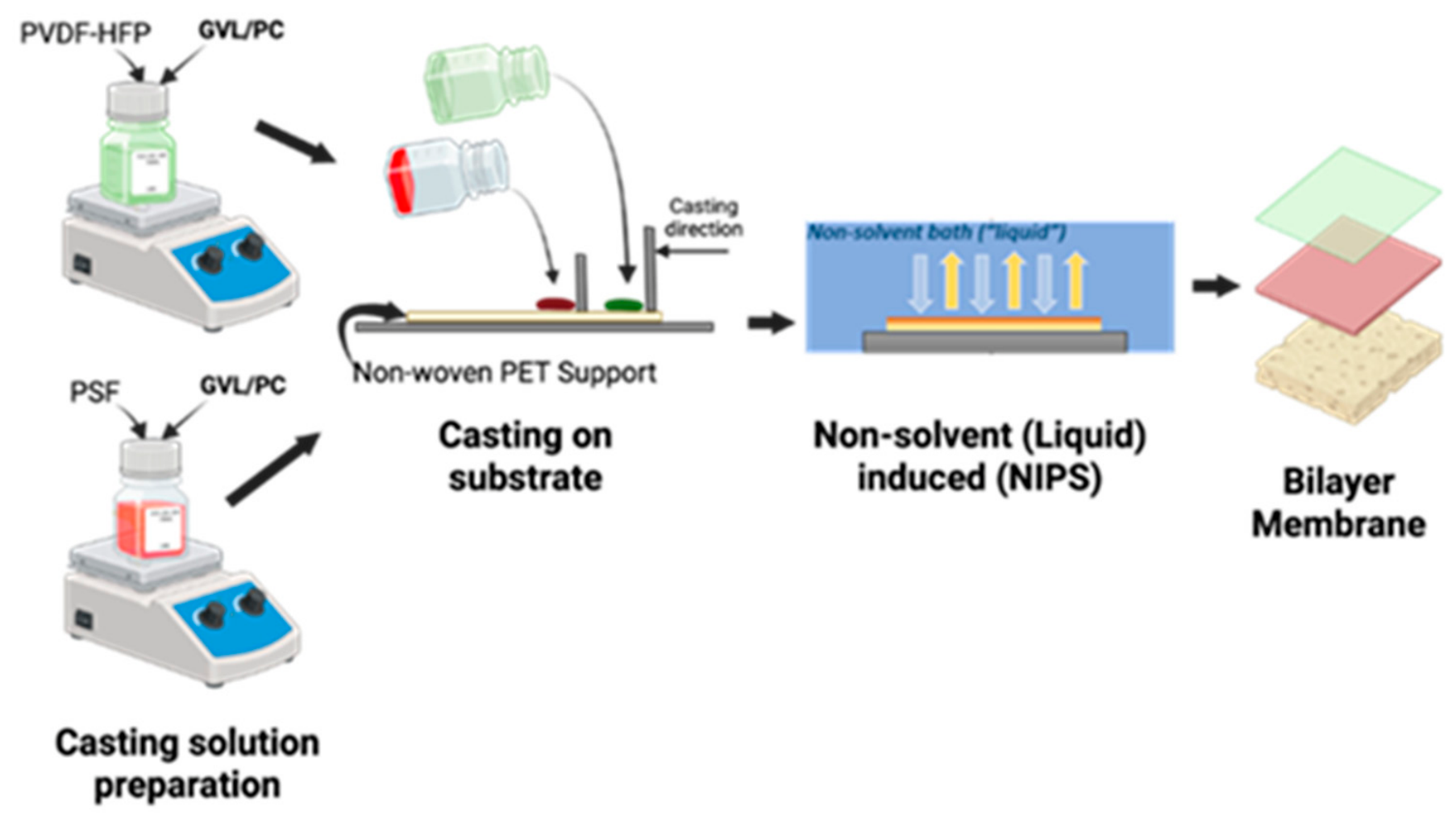
Figure 2.
(a) SEM image of the bilayer membrane cross section; (b) F elemental mapping to show the PVDF top layer; and (c) S elemental mapping to show the PSf bottom layer. .
Figure 2.
(a) SEM image of the bilayer membrane cross section; (b) F elemental mapping to show the PVDF top layer; and (c) S elemental mapping to show the PSf bottom layer. .
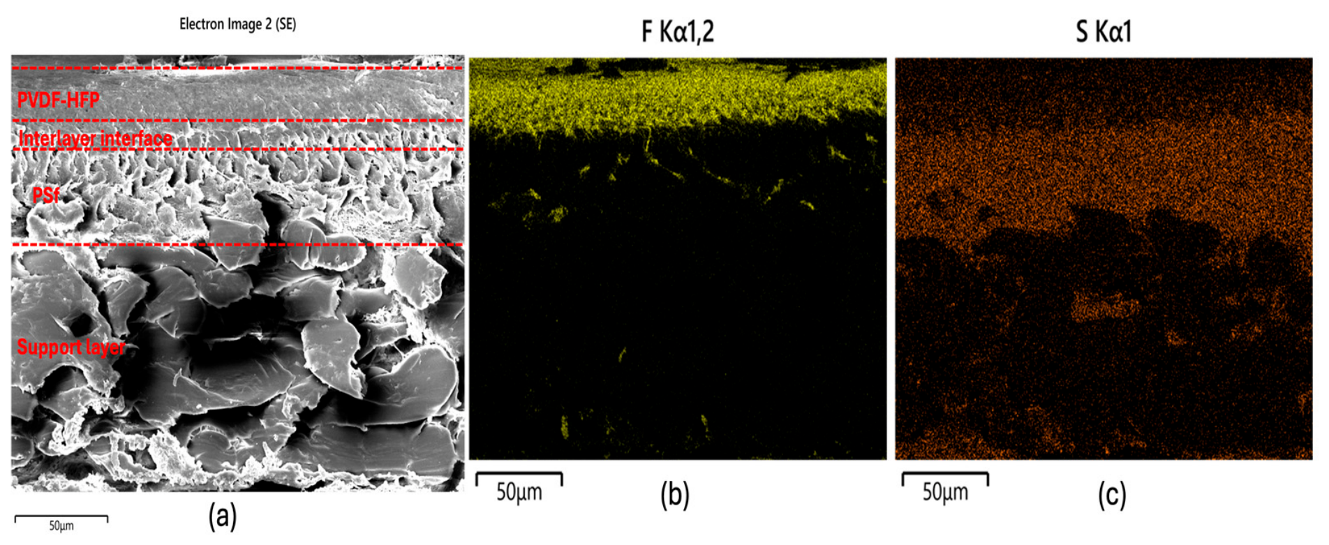
Figure 3.
Surface Scanning Electron Microscopy (SEM) images of single layer (a) PSf, (b) PVDF-HFP and (c) bilayer membranes at a magnification of 2 µm.
Figure 3.
Surface Scanning Electron Microscopy (SEM) images of single layer (a) PSf, (b) PVDF-HFP and (c) bilayer membranes at a magnification of 2 µm.
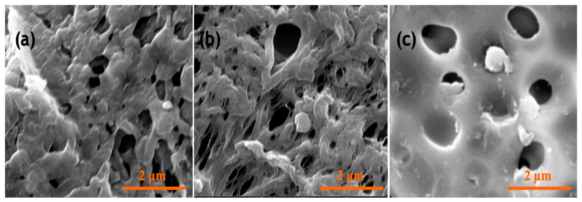
Figure 4.
Hydrophobicity of 17 wt% and 22 wt% PSf, PVDF-HFP and bilayer membranes.
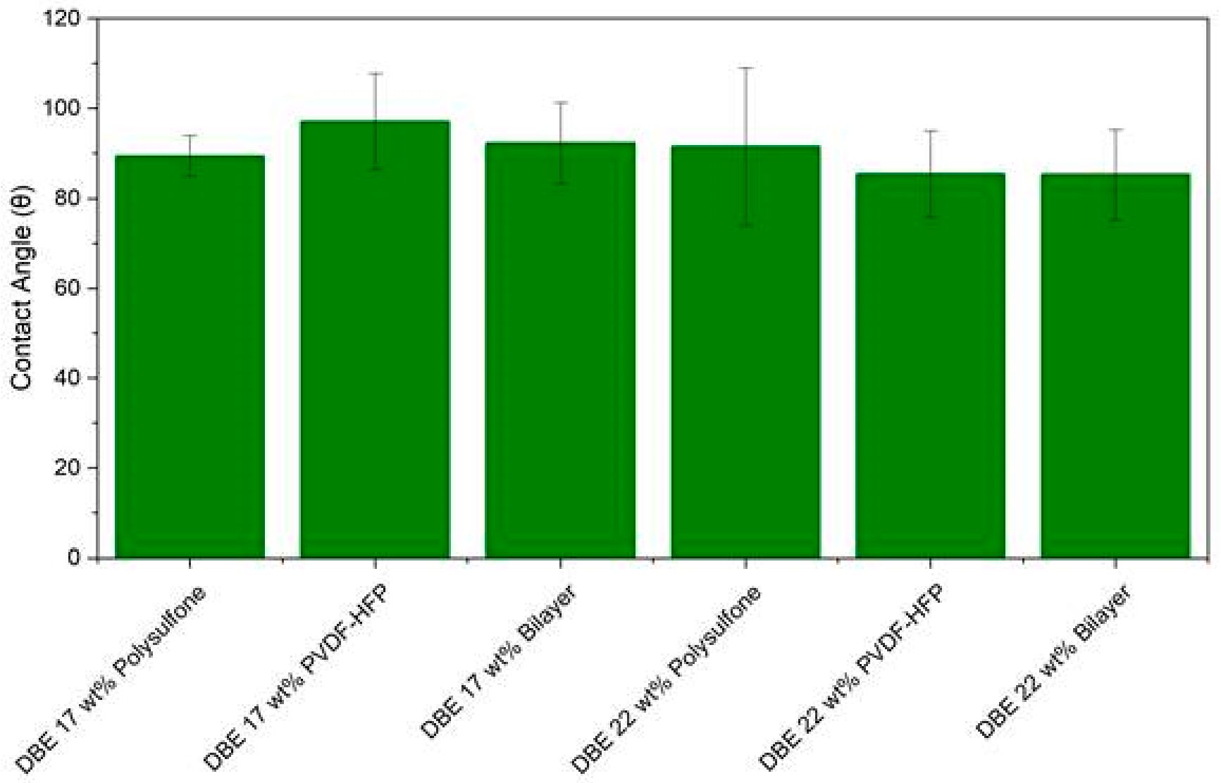
Figure 5.
Water flux of DBE and SDC membranes.
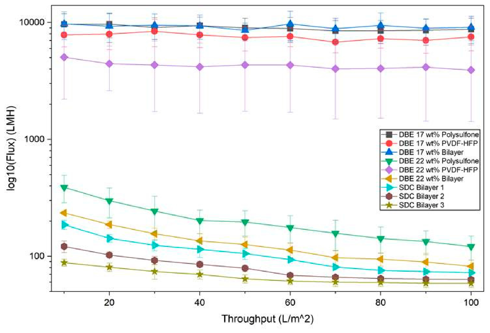
Figure 6.
Solute rejection of DBE and SDC membranes.
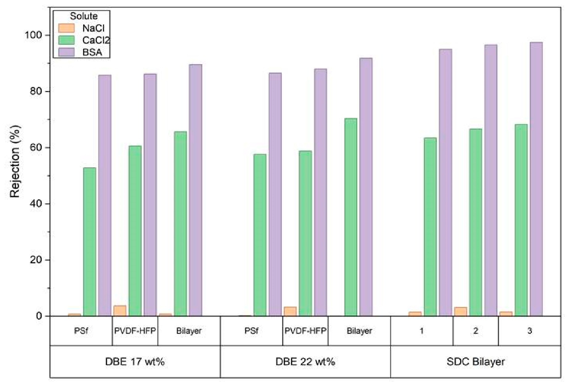

Table 1.
Solutes tested for rejection experiments and initial feed concentrations.
| Solute Tested | Type of Contaminant | Feed Concentration | Size of Solute |
|---|---|---|---|
| Sodium Chloride (NaCl) | Monovalent Ion | 100 ppm | 0.36 nm |
| Calcium Chloride (CaCl2) | Divalent Ion | 100 ppm | 0.41 nm |
| Bovine Serum Albumin (BSA) | Protein | 100 ppm | 7.1 nm |
Table 2.
Average Young's Modulus (in MPa) of membranes with varying polymer types with standard deviation.
Table 2.
Average Young's Modulus (in MPa) of membranes with varying polymer types with standard deviation.
| . | PVDF-HFP/PolarClean/GVL | Bilayer PolarClean/GVL | |
|---|---|---|---|
| Young’s Modulus (MPa) | 196.6 ± 3.93 | 159.6 ± 2.01 | 216.3 ± 11.53 |
Disclaimer/Publisher’s Note: The statements, opinions and data contained in all publications are solely those of the individual author(s) and contributor(s) and not of MDPI and/or the editor(s). MDPI and/or the editor(s) disclaim responsibility for any injury to people or property resulting from any ideas, methods, instructions or products referred to in the content. |
© 2026 by the authors. Licensee MDPI, Basel, Switzerland. This article is an open access article distributed under the terms and conditions of the Creative Commons Attribution (CC BY) license (http://creativecommons.org/licenses/by/4.0/).
Copyright: This open access article is published under a Creative Commons CC BY 4.0 license, which permit the free download, distribution, and reuse, provided that the author and preprint are cited in any reuse.