
Submitted:
10 July 2026
Posted:
13 July 2026
You are already at the latest version
Abstract
Cobalt-based electrocatalysts are promising alternatives to costly noble metal OER catalysts, yet they suffer poor conductivity, insufficient active sites and severe structural degradation during electrolysis. Herein, hollow Co3O4 microspheres were fabricated via solvothermal synthesis and calcination, followed by gas-phase phosphorus doping and controlled NaBH4 reduction to prepare a series of defective Co3O4/P−B electrocatalysts. Multiple characterizations including XRD, SEM, TEM, EPR and XPS confirm that 1 h mild reduction retains the intact hollow spherical framework while introducing abundant lattice defects. P doping and reduction jointly adjust the electron density of Co and P atoms without altering oxygen’s chemical state. Electrochemical tests in 1.0 M KOH reveal that Co3O4/P−B1 delivers optimal OER performance: an overpotential of 282 mV at 10 mA·cm−2 and a small Tafel slope of 88.7 mV·dec−1. It maintains negligible current decay over 70000 s chronoamperometry measurement. Post-catalysis XPS verifies that surface adsorbed *OOH species act as core active sites. This work proposes a facile morphology-defect co-regulation strategy to design high-stability hollow cobalt-based alkaline OER electrocatalysts.
Keywords:
Co3O4
; hollow structure
; oxygen evolution reaction
1. Introduction
Electrochemical water splitting for hydrogen production is a key technology for integrating intermittent renewable energy and achieving carbon neutrality. However, the anodic oxygen evolution reaction (OER), which involves a four-electron transfer process, suffers from high kinetic barriers and slow reaction rates, making it a critical bottleneck limiting the overall efficiency of water electrolysis. Commercial OER catalysts such as IrO2 and RuO2 are expensive and resource-limited, rendering them unsuitable for large-scale industrial applications. Therefore, cobalt-based non-precious metal catalysts—abundant in reserves and tunable in oxidation states—have become the primary research focus. Nevertheless, pure cobalt-based nanomaterials suffer from drawbacks including facile aggregation, poor electrical conductivity, sintering-induced deactivation during electrolysis, and insufficient exposure of active sites. Hollow spherical nanostructures, with their unique hollow cavities, hierarchical mesoporous architectures, and high specific surface areas, have emerged as ideal morphologies for modifying cobalt-based catalysts. When combined with strategies such as carbon-based supports and bimetallic doping, these structures can significantly enhance the electrocatalytic performance of cobalt-based materials, making them a current research hotspot in hydrogen generation via electrocatalysis.
Currently, multiple mature and controllable synthesis methods have been established for hollow cobalt-based composite catalysts, primarily categorized into template-assisted and template-free approaches, each offering distinct advantages and suited to different modification requirements. The hard-template method is the dominant strategy for fabricating cobalt-based catalysts on hollow carbon spheres. Common sacrificial templates include polystyrene (PS) microspheres, PS-b-PAA block copolymers, and silica (SiO2) nanoparticles. By coating carbon precursors onto the template surface, loading cobalt precursors, and then undergoing high-temperature carbonization followed by etching to remove the template, one can precisely control the particle size, shell thickness, and pore structure of the resulting hollow spheres. This enables the preparation of two types of cobalt-based hollow carbon composites: cavity-confined (MxOy@HCSs) and surface-loaded (MxOy/HCSs) configurations. Additionally, doping modifications can be applied to optimize the electronic structure of the materials[1]. Based on this approach, researchers have developed improved techniques such as simplified calcination and simultaneous nitrogen doping with cobalt loading, effectively enhancing the dispersion of active cobalt species and preventing particle aggregation[13,14]. However, this method remains labor-intensive, time-consuming due to prolonged etching cycles, and thus faces challenges in scaling up for industrial production.
The template-free method, centered on Ostwald ripening and self-assembly, enables the controlled synthesis of double-layer hollow cobalt-based particles via a one-pot solvothermal reaction. By leveraging the dissolution-recrystallization mechanism of particles, it constructs hollow structures, and shell thickness can be easily adjusted by tuning reaction parameters, offering a simple preparation process [11]. However, this approach struggles to in situ incorporate conductive carbon frameworks, resulting in insufficient conductivity of pure cobalt hollow materials that require secondary modification. Additionally, the bio-template method utilizes natural ferritin protein cages to gently synthesize ultrafine hollow cobalt oxide nanoparticles with uniform and controllable particle sizes. Nevertheless, biological templates are prone to decomposition at high temperatures, limiting their application in producing large-scale carbon-composite catalysts, thus restricting practical applicability[12]. Beyond single-hollow structure fabrication, multi-metal composite modification techniques have gradually matured. Through co-doping with metals such as Mn, Fe, Zn, and Ni, combined with morphology control of hollow structures, novel composites—including multi-shell manganese-cobalt composite hollow spheres, zinc-cobalt bimetallic phosphide hollow arrays, and cobalt-doped iron hydroxide hollow nanocages—can be fabricated, achieving synergistic optimization of structural and electronic properties[5,8,9].
The coupling effect between hollow structures and multi-metal co-modification comprehensively enhances the alkaline OER catalytic performance of cobalt-based materials. On one hand, the hollow cavity stores electrolyte and accelerates oxygen desorption, alleviating bubble accumulation and blockage of active sites. Multilevel mesoporous shells maximize exposure of coordinatively unsaturated edge atoms, increasing electrochemically active surface area. Meanwhile, the confined hollow environment effectively suppresses sintering of cobalt-based nanoparticles, metal ion leaching, and lattice fragmentation, thereby improving long-term catalyst stability[1,3]. On the other hand, carbon-based hollow supports establish continuous conductive networks, overcoming the poor conductivity of cobalt-based materials, while bimetallic doping precisely tunes the d-band center, balancing adsorption energies of OER intermediates such as *OH, *O, and *OOH, and lowering the energy barrier of the rate-determining step[8,9]. Numerous studies confirm that modified hollow cobalt-based catalysts exhibit outstanding catalytic performance: for instance, CoOOH-modified hollow carbon sphere catalysts achieve an overpotential of only 340 mV at 10 mA·cm-2 current density, with extremely low current decay during long-term testing[10]; zinc-cobalt bimetallic phosphide hollow arrays enable full water-splitting systems to reach target current densities at just 1.63 V, operating stably for 50 hours[5]; multi-shell manganese-cobalt composite hollow spheres even achieve an ultra-low overpotential of 270 mV, demonstrating significant catalytic advantages over conventional pure cobalt materials[8,9].
Despite these advances, several shortcomings and research gaps remain in the study of hollow cobalt-based water-splitting catalysts. The mechanisms underlying cavity confinement effects for different cobalt loading positions, the quantitative influence of carbon reduction on cobalt valence distribution, and the quantifiable rules by which hollow structures alleviate pore blockage are still unclear[1,3]. Various synthesis methods also face limitations: hard-template methods are costly, template-free approaches suffer from inadequate conductivity, and bio-template methods lack thermal stability. Moreover, issues such as cobalt component leaching and aggregation of active phases during catalysis have not been fully resolved[12,13,14]. Future research should focus on developing simple and low-cost synthesis strategies, precisely controlling the coupling interactions at the carbon-cobalt hollow interface and metal loading levels, and elucidating the catalytic mechanisms involving hollow confinement and multi-metal synergy, providing theoretical foundations and technical pathways for designing high-performance, scalable non-precious metal water-splitting catalysts.
2. Experimental Equipment
2.1. Materials
The reagents used in the experiment, including hexahydrate cobalt nitrate (Co(NO3)2·6H2O AR), deionized water (H2O AR), glycerol (C3H8O3 AR), isopropanol (C3H8O AR), and anhydrous ethanol (C2H5OH AR), were all purchased from Guojun Group Chemical Reagents Co., Ltd.; sodium hypophosphite (NaH2PO2 AR) was obtained from Shanghai Aladdin Biochemical Technology Co., Ltd.; and the 5% mass fraction Nafion solution was provided by Alfaesha (China) Chemical Co., Ltd. All the reagents were used directly in the experiment without further purification after purchase.
2.2. Catalyst Preparation
Synthesis of spherical cobalt precursors: Weigh 0.232 g of Co(NO3)2·6H2O and dissolve it in a mixed solvent consisting of 40 mL isopropanol and 8 mL glycerol. Vigorously stir until the solute is completely dissolved. Transfer the resulting clear precursor solution to a 100 mL stainless steel water bath reactor with a polytetrafluoroethylene inner lining. Seal it and place it in an oven at 180 ℃ for a water bath reaction for 6 hours. After the reaction, let it cool naturally to room temperature, collect the precipitate at the bottom of the reactor, and use multiple centrifugal washes with anhydrous ethanol and deionized water alternately to remove surface residual organic ligands and metal ion impurities. The washed sample is placed in a vacuum drying box at 60 ℃ for overnight drying to obtain spherical cobalt precursor powder.
Preparation of Co3O4 hollow spheres by calcination: Place the aforementioned spherical cobalt precursor in an alumina crucible and put it into an air atmosphere muffle furnace for high-temperature pyrolysis and calcination. The temperature ramping program is set as follows: increase the temperature at a rate of 0.5 ℃ per minute from room temperature to 500 ℃, and hold for 2 hours; after the calcination is completed, let it cool naturally in the furnace to room temperature, and obtain pure-phase Co3O4 hollow microspheres.
Preparation of phosphorus-doped Co3O4/P hollow spheres: P-type doped modified Co3O4 hollow spheres were prepared by the gas-phase phosphatization method using a tube furnace. 75 mg of the above Co3O4 hollow powder was placed in the downstream crucible, and 750 mg of disodium hydrogen phosphate (NaH2PO2) was placed in the upper porcelain boat of the tube furnace as the phosphorus source; high-purity nitrogen gas was continuously introduced as a protective and carrier gas, and the gas flow rate was kept stable. The temperature rise program of the tube furnace: the heating rate was 2 ℃·min-1, from room temperature to 350 ℃, and phosphatization treatment was carried out at a constant temperature for 3 hours. After the tube furnace cooled down to room temperature, the black product was collected, and the surface soluble phosphates impurities were removed by multiple centrifugal washings with anhydrous ethanol and deionized water, and then dried to obtain phosphorus-doped Co3O4 hollow spheres, labeled as Co3O4/P.
Preparation of borohydride reduction modified Co3O4/P-B series samples: Prepare borohydride reduction modified Co3O4/P-B samples. Prepare a 3 mol・L-1 NaBH4 reduction solution, immerse equal amounts of Co3O4/P powder in the reduction system, and control the reduction time successively as 1 h, 2 h, and 3 h; the three groups of reduction products are labeled as Co3O4/P-B1, Co3O4/P-B2, and Co3O4/P-B3. After the reduction is completed, use anhydrous ethanol and deionized water to alternate centrifugal cleaning of the powder to remove residual reducing agents and by-products, then dry at 60 ℃ in a vacuum drying oven for 10 hours, collect the black defect modified powder for future use.
2.3. Characterizations
X-ray Diffraction (XRD): The crystal phase structure of all catalyst samples was characterized using the D8-Discover X-ray diffractometer from Bruker. The test source was Cu target Kα radiation, the scanning rate was set at 10 °・min⁻¹, and the 2θ scanning range was 20°–80°.
Scanning Electron Microscope (SEM): The FEI Inspect F50 field emission scanning electron microscope (Sirion) was used to observe the microscopic surface morphology of the catalysts, and the elemental distribution and content analysis were completed simultaneously with an X-ray energy spectrometer (EDS).
Transmission Electron Microscope (TEM): The G220 transmission electron microscope was used for transmission characterization, and the lattice stripe information of the samples was observed using high-resolution transmission electron microscopy (HRTEM). Sample pre-treatment process: A small amount of the sample powder was dispersed in anhydrous ethanol, and ultrasonic oscillation for 30 minutes was used to achieve uniform dispersion; then the dispersion liquid was dropped onto a copper micro-gate carrier, and the ethanol was completely evaporated before the sample was tested on the machine.
X-ray Photoelectron Spectroscopy (XPS): The XPS test was conducted using the ESCALAB 250Xi X-ray photoelectron spectrometer from Thermo Scientific. All spectra were corrected for charge state using the standard binding energy of the C 1s orbit 284.8 eV, and then the element valence and surface chemical environment were analyzed.
Electron Paramagnetic Resonance Spectroscopy (EPR): The EPR signal of the samples was collected using the A320 electron paramagnetic resonance spectrometer from Bruker, which was used for qualitative analysis of defect structures such as oxygen vacancies in the material.
2.4. Electrocatalytic Test
The electrochemical test was conducted using the Chenhua electrochemical workstation platform (660E) in a standard three-electrode system. The glassy carbon electrode coated with the sample was used as the working electrode, the Ag/AgCl electrode (3.0 M KCl) as the reference electrode, and the graphite rod as the counter electrode. The experiment was carried out in 1 M KOH electrolyte. The preparation of the working electrode was done as follows: 5.0 mg of the catalyst was ultrasonically dispersed in a 500 μL water, 480 μL ethanol, and 20 μL Nafion (5 wt %) mixed solution for 30 minutes of ultrasonic oscillation. Then, 5 μL of the dispersant was dropped onto the clean glassy carbon electrode surface (diameter 3 mm, S = 0.0706 cm2) using a pipette. The test conditions are as follows: (1) The OER curve of the sample was obtained at room temperature by linear sweep voltammetry (LSV with a scan rate of 2 mV s-1) (the potentials described in this chapter were converted to standard hydrogen electrode potential Evs.RHE = Evs.Ag/AgCl+0.059 pH+0.1976, and all potentials in the LSV polarization curve were not corrected for IR). (2) The charge transfer kinetics of the OER process was studied by electrochemical impedance spectroscopy (EIS), with the measurement frequency ranging from 105 Hz to 0.01 Hz and an amplitude of 10 mV. (3) The i-t curve was measured at a constant current density of 10 mA cm-2 to examine the stability of the electrocatalyst. (4) According to the Tafel equation, η = a + blog j, where η represents the overpotential, a represents the content, b represents the Tafel slope, and j represents the current density. The formula for calculating the overpotential η is: η = E(RHE)-1.23 V. (5) The double layer capacitance (Cdl) of the catalyst was measured according to the cyclic voltammetry (CV) in the illegal Faradaic interval, with scan rates of 20 mV s-1, 40 mV s-1, 60 mV s-1, 80 mV s-1, and 100 mV s-1.
3. Results and Discussion
Pure Co3O4 and Co3O4/P-B1 samples were prepared according to the synthesis process shown in Figure 1. X-ray diffraction (XRD) was employed to characterize the phase composition of both materials, and the results are presented in Figure 1. For the pure Co₃O₄ sample, the diffraction peaks marked with diamonds in the pattern appear at 31.2°, 36.8°, 44.8°, 55.6°, 59.3°, and 65.2°, which correspond exactly to the (220), (311), (400), (422), (511), and (440) crystal planes of Co3O4 as indicated by the standard PDF card (No. 42-1467). In comparison, the XRD pattern of the Co3O4/P-B1 sample shows a significant reduction in peak intensities after modification through phosphorus doping followed by NaBH₄ reduction, while the peak positions remain largely consistent with those of standard Co3O4. These results indicate that the combination of phosphorus doping and sodium borohydride reduction does not alter the main crystalline phase of Co3O4 but disrupts crystal integrity, leading to reduced crystallinity.
The microstructure of the three samples, namely the calcined pure Co3O4, phosphorus-doped modified Co3O4/P, and borohydride reduction-treated Co3O4/P-B1, was characterized by scanning electron microscopy (SEM).
As shown in Figure 2a and d, the pure Co3O4 prepared by calcination exhibited a regular spherical morphology, with a smooth and flat surface. Figure 2i is the SEM image of a broken microsphere, allowing for a clear observation of the internal hollow structure. The formation of this hollow sphere originated from the Kirkendall effect during the precursor calcination process[16,17,18,19]. The internal substances diffused outward and gradually constructed the cavity, eventually forming a complete hollow spherical framework. After phosphating treatment with sodium hypophosphite gas phase, the P element was successfully doped onto the surface of the Co3O4 spheres. By comparing the morphology of Co3O4/P in Figure 2b and e, it can be seen that the surface roughness of the phosphorus-doped microspheres significantly increased, with a large number of nano-protruding particles distributed on the surface.
Figure 2c and f show that the overall spherical framework of Co3O4/P-B1 obtained by liquid-phase reduction with NaBH4 is not significantly different from Co3O4/P, proving that the reduction modification process does not damage the original hollow spherical morphology of the material. Further verification was conducted using transmission electron microscopy (TEM) on Co3O4/P-B1[20,21,22,23,24]: Figure 2j directly confirmed the presence of a large number of nano-particle protrusions on the sphere surface; Figure 2k clearly distinguished the internal hollow cavity structure of the spherical material, which was consistent with the SEM characterization conclusion.
The lattice defect levels of the Co3O4/P and Co3O4/P-B1 samples were quantitatively characterized by electron paramagnetic resonance (EPR) spectroscopy. The test results are shown in Figure 3. At the g = 2.01 characteristic signal, the EPR signal intensity of Co3O4/P-B1 was significantly higher than that of Co3O4/P. This signal corresponds to the unpaired electrons within the material, indicating that the concentration of unpaired electrons in the sample after sodium borohydride reduction treatment has significantly increased, directly proving that Co3O4/P-B1 has more abundant lattice defects[25].
To investigate the evolution of the chemical environment of surface elements in the samples before and after NaBH4 reduction modification, X-ray photoelectron spectroscopy (XPS) tests were further conducted. Figure 4a shows the Co 2p high-resolution spectrum: the characteristic peak corresponding to Co2+ at 798.53 eV for the pre-reduction state shifted to a lower binding energy of 797.28 eV after reduction; the peak position of Co 2p 3/2 shifted from 782.28 eV to 781.73 eV. The shift of the characteristic peaks to the lower energy region indicates an increase in the electron cloud density around the Co atoms, which is conducive to the charge transport in the electrocatalytic process. Both of the two spin-orbit splitting peaks showed a consistent shift pattern, confirming that the reduction process regulated the electronic distribution at the Co sites[26,27,28,29]. Figure 4b shows the P 2p fine spectrum, where the characteristic peak belonging to the P-O bond shifted from 134.28 eV to 133.73 eV, indicating that the liquid-phase reduction changed the electronic coordination environment around the P atoms. Figure 4c shows the O1s spectrum, and the O1s characteristic peaks of the samples before and after reduction both remained stable at 532.03 eV, with no significant shift in the peak position, proving that the chemical environment of the oxygen sites was not affected by the NaBH4 reduction process and had excellent chemical stability.
Based on the XPS analysis results, it can be concluded that NaBH4 reduction modification only regulates the local electronic structure of Co and P elements. Both types of atoms undergo significant electron rearrangement, while the coordination and electronic state of the surface oxygen atoms remain basically stable.
Using a 1.0 mol·L-1 KOH aqueous solution as the electrolyte and adopting a standard three-electrode electrochemical testing system, the alkaline oxygen evolution catalytic performance of four catalysts, namely Co3O4/P, Co3O4/P-B1, Co3O4/P-B2, and Co3O4/P-B3, was systematically evaluated[30].
Figure 5a and b show the linear sweep voltammetry (LSV) curves of each sample. Under an electric current density of 10 mA·cm-2, the oxygen evolution overpotential η10 of Co3O4/P-B1 was only 282 mV (Figure 5b), which was significantly better than that of Co3O4/P (312 mV), Co3O4/P-B2 (337 mV), and Co3O4/P-B3 (342 mV), demonstrating the optimal intrinsic activity for OER. With the increase in the reduction time of NaBH4, the oxygen evolution performance of the catalyst gradually declined, indicating that 1 hour of reduction treatment was the optimal condition for regulating the catalytic activity of this hollow sphere[31].
The Tafel slope can directly reflect the speed of the OER reaction kinetics. The Tafel fitting results corresponding to the four samples are shown in Figure 5c. The Tafel slopes of Co3O4/P, Co3O4/P-B1, Co3O4/P-B2, and Co3O4/P-B3 are 119.3, 88.7, 134.8, and 149.4 mV·dec-1, respectively. Co3O4/P-B1 has the smallest Tafel slope, indicating that its charge transfer kinetics rate is the fastest, which is consistent with the low overpotential test results.
Long-term service stability is a key indicator for evaluating the practical value of electrocatalysts. In this work, a 70,000-second constant current durability test was conducted on each sample using the chronoamperometry (i-t) curve (Figure 5d). During the test period, the current density of Co3O4/P-B1 decreased slightly, demonstrating excellent long-term electrochemical stability. The comprehensive activity and durability can determine that Co3O4/P-B1 is a high-performance alkaline OER electrocatalytic material[32,33].
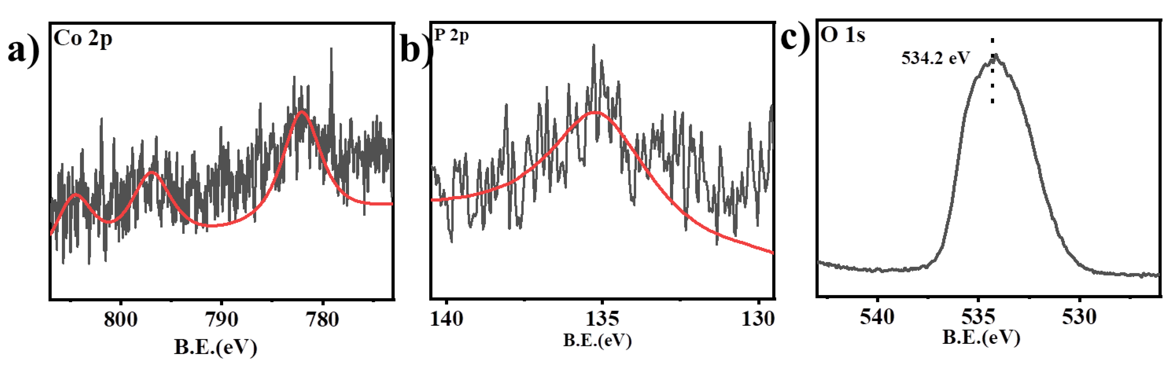
To reveal the origin of the catalytic reaction activity, XPS characterization was performed on the Co3O4/P-B1 sample after the OER test (Figure 6). By comparing the fine spectra before and after the reaction, it can be seen that there is no significant shift in the binding energies of the Co 2p and P 2p characteristic peaks, indicating that the Co and P elements are chemically stable in the electrolysis process. The O 1s characteristic peak shifted from the initial 532.03 eV to 534.2 eV, which corresponds to the adsorbed state of *OOH intermediate, confirming that metal-bound hydroxide species are generated on the catalyst surface during the OER process. This type of adsorbed intermediate is the core active site of the catalytic reaction[34,35].
4. Conclusions
In this work, hollow Co3O4 microspheres were synthesized and modified via phosphorus doping and gradient NaBH4 reduction to obtain defective OER electrocatalysts. Morphological characterizations prove phosphorus doping roughens sphere surfaces, while 1 h moderate reduction does not destroy the hollow cavity structure. EPR results demonstrate abundant lattice defects are generated on Co3O4/P−B1. XPS analysis indicates reduction only rearranges electron distribution of Co and P without changing oxygen coordination environment. Electrochemical evaluations confirm Co3O4/P−B1 exhibits superior OER activity and long-term stability among all samples. The synergistic advantages originate from three aspects: hollow structure accelerates oxygen bubble desorption and exposes abundant edge active sites; phosphorus doping improves intrinsic conductivity; rich defects optimize adsorption energy of OER intermediates. Post-reaction XPS identifies surface metal-bound *OOH as the dominant catalytic active intermediate. This study provides a simple integrated strategy combining hollow morphology engineering and defect modulation to develop low-cost, durable cobalt-based electrocatalysts for alkaline water electrolysis.
Acknowledgments
The authors declare that artificial intelligence language models have been applied to refine the sentence structure, academic expression and wording of this manuscript. The use of AI tools does not affect any original research content, experimental data, scientific interpretation and research conclusions presented in this work. We gratefully acknowledge the support of the Anhui Province Higher Education Science Research Project (grant numbers: 2025AHGXZK31131, 2025AHGXZK40616, 2025AHGXZK40616, 2024AH040133, 2024AH050873 and 2025AHGXZK60048); Anhui Province Quality Project (2024cxtd218; 2025jyxm0730); Anhui Vocational College's School-level Quality Project (2023yjjyxm16), School-level Research Platform of Anhui Vocational Technology College (2024xjpt03); Training Program for Young and Middle-Aged Teachers of Colleges and Universities in Anhui Province(YQZD2024073);Ministry of Education Committee for Teaching Guidance on the Chinese-style Apprenticeship System in Vocational Colleges (ZJZX002) China Association of Adult Education (2025-0522ZB).
Conflicts of Interest
The author declares no competing financial interest.
References
- Mente P., Mashindi V,. Phaahlamohlaka T. N., et al. Oxidation of Benzyl Alcohol Using Cobalt Oxide Supported Inside and Outside Hollow Carbon Spheres [J]. ChemistryOpen, 2021, 10 (6): 618-626.
- Adamson W., Jia C., Li Y., et al. Cobalt oxide micro flowers derived from hydrothermal synthesised cobalt sulphide pre-catalyst for enhanced water oxidation [J]. Electrochimica Acta, 2020, 355: 136802.
- Fester J., García-Melchor M., Walton A. S., et al. Edge reactivity and water-assisted dissociation on cobalt oxide nanoislands [J]. Nature Communications, 2017, 8 (1): 14169.
- Zhang J. Y.,. Lv L., Tian Y., et al. Rational Design of Cobalt−Iron Selenides for Highly Efficient Electrochemical Water Oxidation [J]. ACS Applied Materials & Interfaces, 2017, 9 (39): 33833-33840.
- Song Y., Wang Q., Liu X., et al. Nickel Foam-Loaded Zn/Co Bimetallic Phosphide as an Efficient Bifunctional Electrolytic Water Catalyst [J]. Catalysis Letters, 2024, 154 (10): 5101–5109.
- Wang H. S., Lei J., Wu J. S., et al. Sustainable water oxidation enabled by a complex-doped cobalt oxide electrode [J]. Nature Communications, 2026, 17: 1302.
- Ahmad M., Wu K., Ullah I., et al. Tailoring Cobalt-Based Nanomaterials through Doping and Vacancy Engineering for Advanced Hydrogen Evolution Reaction (HER) and Oxygen Evolution Reaction (OER) Electrolysis [J]. Small, 2026: e73992.
- Indra A., Menezes P. W., Das C., et al. Alkaline electrochemical water oxidation with multi-shelled cobalt manganese oxide hollow Spheres [J]. Chemical Communications, 2017, 53: 8641.
- Han X. X., Liu C., Tang Y., et al. Unveiling the role of cobalt doping in optimizing ammonia electrosynthesis on iron–cobalt oxyhydroxide hollow nanocages [J]. Journal of Materials Chemistry A, 2023, 11: 14424–14431.
- Xiao T. J., Zhao L. X., Ge H. H., et al. Cobalt oxyhydroxide decorating hollow carbon sphere: A high-efficiency multi-functional material for Li-S batteries and alkaline electrocatalysis [J]. Chemical Engineering Journal, 2022, 439: 135790.
- Zhang D., Zhu J. Y., Zhang N., et al. Controllable fabrication and magnetic properties of double-shell cobalt oxides hollow particles [J]. Scientific Reports, 2015, 5: 8737.
- Kim J. W., Choi S. H., Lillehei P. T., et al. Cobalt oxide hollow nanoparticles derived by bio-templating [J]. Chemical Communications, 2005, 4101–4103.
- Chen Z. K., He D. D., Xu X. J., et al. Coupled cobalt oxide/hollow carbon sphere as an efficient electrocatalyst for the oxygen reduction reaction [J]. RSC Advances, 2016, 6: 34159.
- Duraisamy V., Sudha V., Dharuman V., et al. Highly Efficient Electrochemical Sensing of Acetaminophen by Cobalt Oxide-Embedded Nitrogen-Doped Hollow Carbon Spheres [J]. ACS Biomaterials Science & Engineering, 2023, 9: 1682−1693.
- Bai H. T., Dong D. R., Wang Z. L., et al. Preparation of cobalt-nitrogen Co-doped porous carbon catalysts in zinc-air battery[J]. Plating and Finishing, 2026, 48(5): 20-26.
- Gu Yi H.,Ren H. X.,Bi K. L.,et al. Research progress of iridium-based oxygen evolution catalyst for water electrolysis with proton exchange membrane[J]. Plating and Finishing,2025, 47(9):90-96,118.
- Li Z. W., Xu X., Zhou J. X.. Magnetic field-regulated fabrication and high-efficiency hydrogen evolution performance of porous nickel-cobalt electrodes[J]. Plating and Finishing, 2026, 48(2): 146-153.
- Zheng, G. X., Zhu Y. Q., Ming S., et al. Construction of hierarchical porous NiFe/Ni@NM at low current density for efficient oxygen evolution[J]. Plating and Finishing, 2026, 48(5): 13-19, 26.
- Liu, X. et al. Comprehensive understandings into complete reconstruction of precatalysts: synthesis, applications, and characterizations. Adv. Mater. 2021, (33) e2007344 .
- Wang, J. et al. Redirecting dynamic surface restructuring of a layered transition metal oxide catalyst for superior water oxidation. Nat. Catal. 2021, (4): 212–222.
- Lu, Z. et al. Electrochemical tuning of layered lithium transition metal oxides for improvement of oxygen evolution reaction. Nat. Commun. 2014, (5): 43-45.
- Yu, J. et al. Mechanochemical upcycling of spent LiCoO(2) to new LiNi(0.80)Co(0.15)Al(0.05)O(2) battery: an atom economy strategy. Proc. Natl. Acad. Sci. USA 2023, (120): e2217698120.
- Zhu, Y. et al. A High-performance electrocatalyst for oxygen evolution reaction: LiCo0.8 Fe0.2 O2. Adv. Mater. 2015 (27): 7150–7155.
- Zheng, X. B. et al. Enriched-band holes enabling fast oxygen evolution kinetics on atomic-layered defect-rich lithium cobalt oxide nanosheets. Adv. Funct. Mater. 2022, (32) 2200663.
- Kim, Y. et al. Alteration of oxygen evolution mechanisms in layered LiCoO2 structures by intercalation of alkali metal ions. J. Mater. Chem. A 2022, (10): 10967–10978 .
- J. Ding, J. Yang, Z. Wei, et al., Joule Heating for Metal Oxide Electrocatalyst Fabrication: A Fast-Track Strategy for Water Electrolysis, Small 2025, (21): 07087.
- K. Zhao, M. Luo, Y. Zhang, X. Chang, and B. Xu, Coupled Cation–Electron Transfer at the Pt(111)/Perfluoro-Sulfonic Acid Ionomer Interface and Its Impact on the Oxygen Reduction Reaction Kinetics, Nature Catalysis 2025, (8): 46–57.
- K. Song, F. Bao, Z. Wang, et al., Modulation of RuO2 Nanocrystals with Facile Annealing Method for Enhancing the Electrocatalytic Activity on Overall Water Splitting in Acid Solution, Advanced Science 12 (2025): 2409249.
- Y. Liu, L. Wu, Y. Wang, et al., Surface S-Doped Nanostructured RuO2 and Its Anion Passivating Effect for Efficient Overall Seawater Splitting, ACS Nano 2025 (19): 2715–2725.
- Y. Du, J. Liu, J. Chen, et al., Design Principle and Regulation Strategy of Noble Metal-Based Materials for Practical Proton Exchange Membrane Water Electrolyzer, Advanced Energy Materials 2025 (15): 2404113.
- F. Zhang, S. Niu, Y. Zhao, et al., Space-Confined Electrocatalysis for Water Splitting: Synthesis, Performances, and Reaction Mechanism of Nanomaterials Toward High-Performance Catalysis, Angewandte Chemie 2025 (137): 202510651.
- C. Fan, Z. Zang, and X. Zhang, Non-Metal Doping Regulation in Transition Metal and Their Compounds for Electrocatalytic Water Splitting, International Journal of Hydrogen Energy 2024, (56): 1273–1283.
- L.-M. Cao, J. Zhang, L.-W. Ding, Z.-Y. Du, and C.-T. He, MetalOrganic Frameworks Derived Transition Metal Phosphides for Electrocatalytic Water Splitting, Journal of Energy Chemistry 2022, (68): 494–520.
- K. Dong, X. Li, S. Sidra, et al., Interrelating Platinum Single AtomTuned Cobalt Phosphide-Based 2D Flake Network via Multi–Layer Carbon Nanotube Bridges For High-Efficiency Water Splitting, Chemical Engineering Journal 2025, (524): 169674.
- Y. Wang, Y. Zhou, X.-Y. Liu, et al., Single Cobalt Atoms Anchored On In-Situ-Formed Carbon Layers Within Restricted Microenvironment: An Efficient Catalyst For Oxygen Evolution Reaction, Chemical Engineering Journal 2025, (519): 164766.
Figure 1.
XRD characterization of Co3O4 and Co3O4/P-B1.
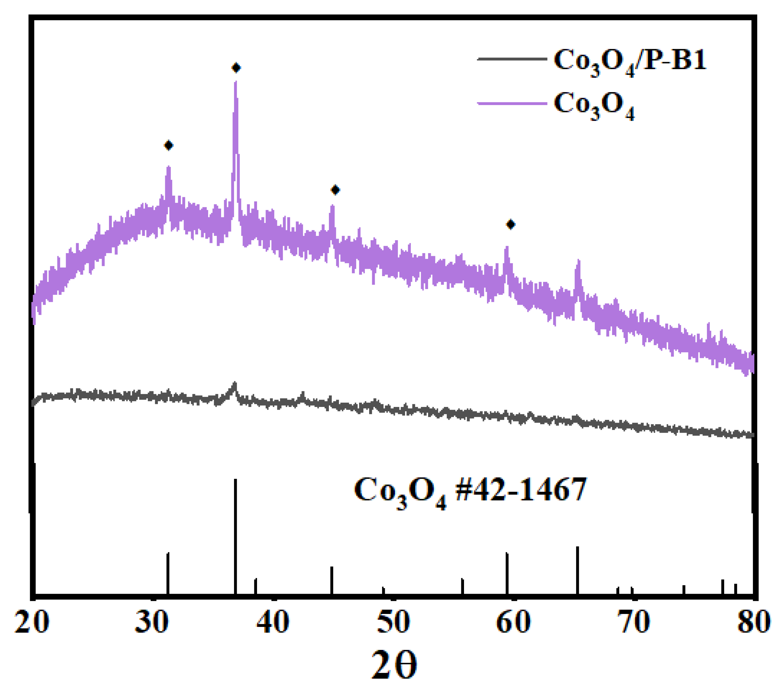
Figure 2.
a,d) SEM image of Co3O4; b,e) SEM images of Co3O4/P; c,f) SEM images of Co3O4/P-B1; i) Co3O4 SEM image of cracked shell; j, k) TEM images of Co3O4/ p-B1.
Figure 2.
a,d) SEM image of Co3O4; b,e) SEM images of Co3O4/P; c,f) SEM images of Co3O4/P-B1; i) Co3O4 SEM image of cracked shell; j, k) TEM images of Co3O4/ p-B1.
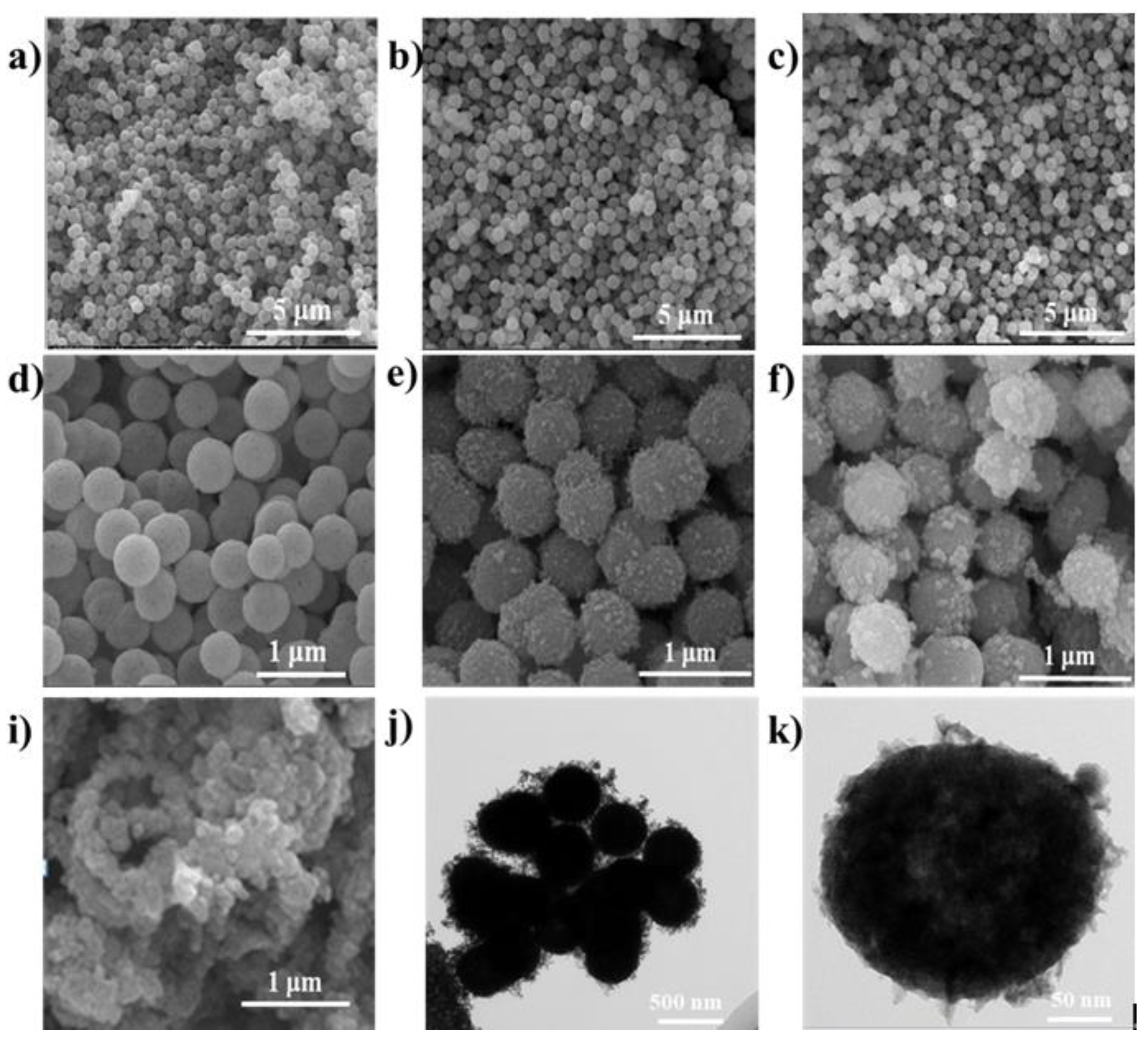
Figure 3.
EPR spectra of Co3O4/P and Co3O4/P-B1.
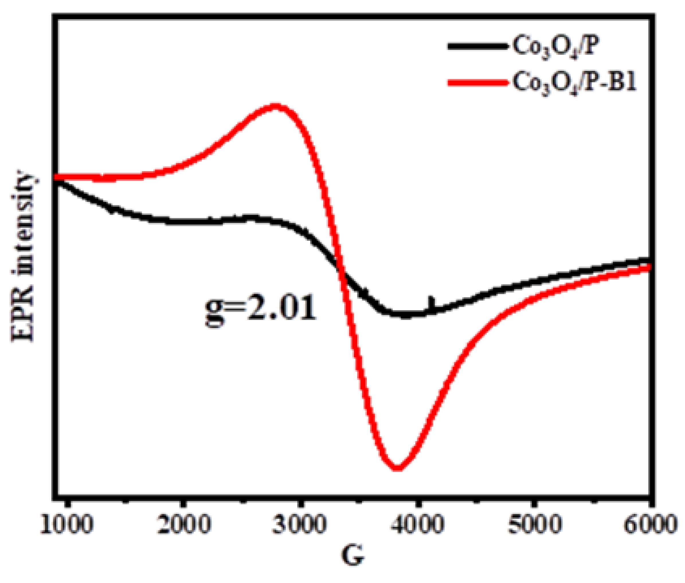
Figure 4.
XPS spectra of Co3O4/P and Co3O4/P-B1 a) Co 2p; b) P 2p; c) O 1s.
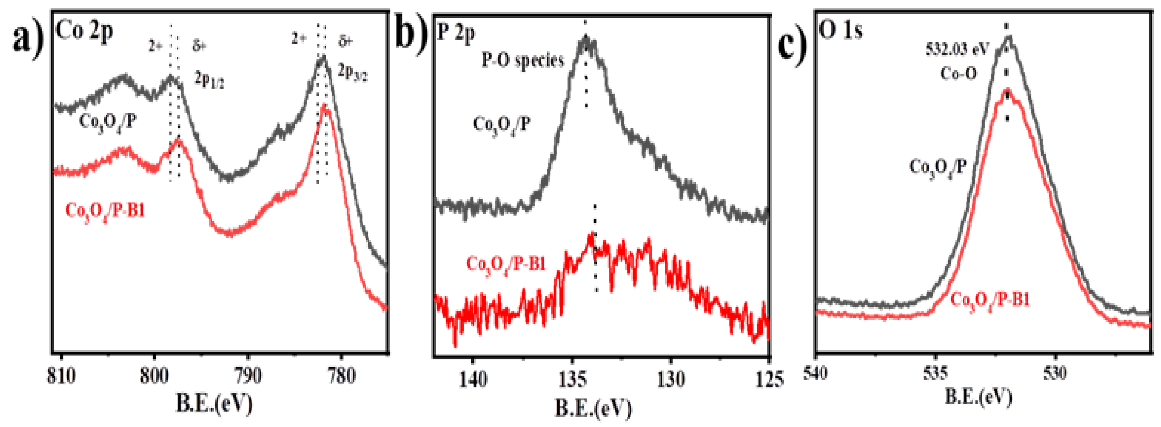
Figure 5.
a) LSV curves of Co3O4/P、Co3O4/P-B1、Co3O4/P-B2 and Co3O4/P-B3;b) The overpotential at Ƞ=10mA cm-2 corresponding to a); c) Taffer curves corresponding to a); d) i-t curves of Co3O4/P-B1.
Figure 5.
a) LSV curves of Co3O4/P、Co3O4/P-B1、Co3O4/P-B2 and Co3O4/P-B3;b) The overpotential at Ƞ=10mA cm-2 corresponding to a); c) Taffer curves corresponding to a); d) i-t curves of Co3O4/P-B1.
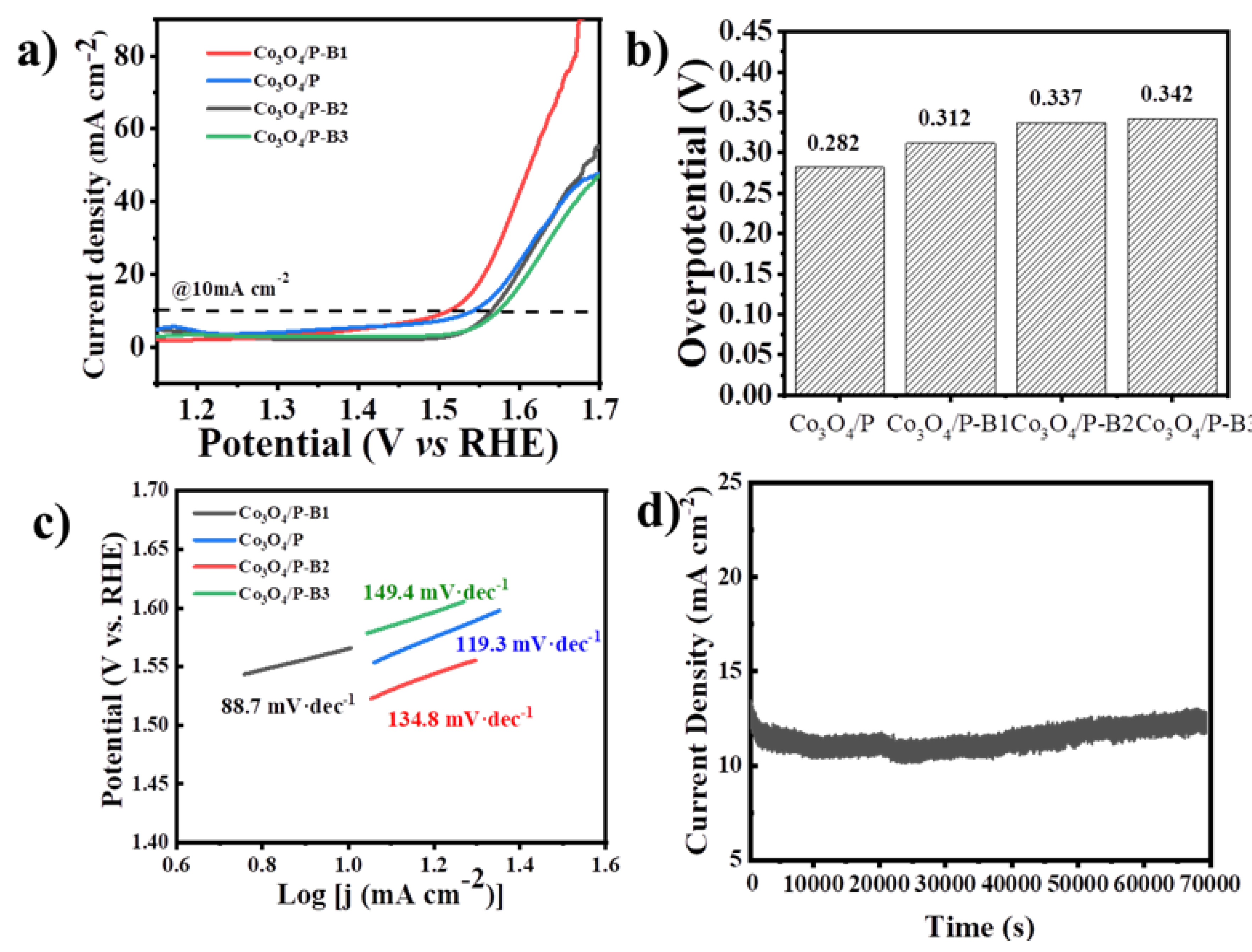
Figure 6.
XPS spectra of Co3O4/P-B1 after OER a) Co 2p; b) P 2p; c) O 1s.
Disclaimer/Publisher’s Note: The statements, opinions and data contained in all publications are solely those of the individual author(s) and contributor(s) and not of MDPI and/or the editor(s). MDPI and/or the editor(s) disclaim responsibility for any injury to people or property resulting from any ideas, methods, instructions or products referred to in the content. |
© 2026 by the authors. Licensee MDPI, Basel, Switzerland. This article is an open access article distributed under the terms and conditions of the Creative Commons Attribution (CC BY) license (http://creativecommons.org/licenses/by/4.0/).
Copyright: This open access article is published under a Creative Commons CC BY 4.0 license, which permit the free download, distribution, and reuse, provided that the author and preprint are cited in any reuse.


