

Submitted:
06 July 2026
Posted:
08 July 2026
You are already at the latest version
Abstract
Compact unmanned aerial vehicles (UAVs) for confined and cluttered spaces are constrained by the exposed, high-speed rotors of conventional multirotors, which are fragile on contact and hazardous near people or obstacles. This paper develops a monocopter, a single-rotor craft that fuses lift and propulsion in one structure, in which propulsion is achieved through a fully integrated electric ducted fan (EDF) and four aerodynamic fins placed within the fan’s exhaust for stabilization. A control-oriented dynamic model is derived from first principles using an energy-based Euler-Lagrange formulation, presented in the manipulator form standard for rotorcraft attitude dynamics and specialized to the single-fan and fin-stabilized configuration. The full configuration-dependent inertia and Coriolis matrices are obtained, and the equivalent body-frame equations expose the gyroscopic coupling that dominates the transverse dynamics. A stability analysis establishes the oblate-inertia condition that governs whether the vehicle’s natural, uncontrolled rotation is stable, then the model is linearized about the spin equilibrium for control, and a four-fin allocation provides three-axis control together with reaction-torque cancellation under a Proportional-Integral-Derivative law on a commercial flight control stack. Simulation reproduces the gyroscopic precession and fin-damped recovery of the spinning body and the deterministic hover spin equilibrium, and an indoor proof-of-concept demonstration confirms that the fabricated prototype hovers with a stable, upright attitude under fin stabilization, the continuous body spin being characterized separately in open loop.
Keywords:
monocopter
; electric ducted fan
; fin stabilization
; rotary-wing UAV
; gyroscopic stability
; Euler–Lagrange model
; passive stabilization
equationEquationEquations equationEquationEquations
1. Introduction
Drones or Unmanned aerial vehicles (UAVs) are increasingly required to operate inside confined, cluttered, and GPS-denied spaces, building interiors, industrial plant, ducts and tunnels, and other enclosed structures where the binding constraints are not endurance or area coverage but the ability to hover, to navigate without external positioning, and, above all, to tolerate contact with the surrounding environment rather than be disabled by it [1]. Conventional multirotors satisfy the first of these needs but not the last: their exposed, high-speed rotors are fragile on contact and constitute a hazard near people, equipment, or flammable atmospheres. The predominant response has been to protect the rotor after the fact, most visibly by enclosing a conventional multirotor in a freely rotating protective cage so that it can collide with obstacles and fly [1]. Effective as it is, caging treats rotor exposure as a problem to be wrapped rather than designed out: it adds mass and aerodynamic drag without removing the underlying exposed-rotor hazard, and it leaves the fundamental incompatibility between a free-flying open rotor and a contact-rich environment unaddressed.
A different line of work pursues mechanical minimalism rather than added protection. The monocopter, a single rotating body that generates lift, propulsion, and stabilization from one structure descends from the autorotating samara, or winged seed, whose efficiency derives from a stable leading-edge vortex (LEV) formed as the seed spins down: dynamically scaled experiments on maple and hornbeam seeds show that the compact LEV elevates lift well above that of non-autorotating seeds, a mechanism shared with hovering insects and bats [2]. The controllable robotic samara established that a single-wing rotating vehicle can be actively controlled: the University of Maryland group identified the heave and attitude dynamics of powered robotic samaras and demonstrated control through cyclic modulation of wing pitch, with body roll and pitch rates coupled to the wing-pitch variation [3,4,5], building on the controllable single-bladed autorotating vehicle developed by Kellas [6]. Subsequent single-actuator and samara-inspired monocopters have shown that hover-capable flight is achievable with extreme mechanical simplicity and competitive endurance [7,8,9,10], and dedicated attitude-estimation methods have been developed for the constant high-spin regime that makes these vehicles difficult to control, where the gravity vector must be extracted from large centripetal-acceleration interference [11].
Despite their appeal, these platforms share two limitations for confined-space operation. First, their control strategies typically rely on cyclic modulation of a single thrust unit or, in the coaxial monocopters developed in the present group, on moving-mass actuation [12] or active thrust vectoring [13]; each adds internal complexity in the form of shifting inertia, sliding components, or articulated hardware, together with the associated mass, latency, and failure modes. Second, none of these designs internalizes its rotor: the propulsion remains exposed, which is acceptable in open air but hazardous in a confined or human-proximate setting. Electric ducted fan (EDF) propulsion offers a way to the second limitation. Shrouding the rotor within a duct improves safety and can enhance power loading relative to an open rotor: an early shrouded single-rotor micro air vehicle with anti-torque vanes achieved a substantial power-loading improvement over the unshrouded rotor even after accounting for the weight of the shroud [14], and ducted-fan platforms have since been shown to be well suited to indoor and human-interaction scenarios [15,16,17]. The same confinement that motivates ducting, however, also complicates it: ducted fans operating near surfaces experience large, sometimes dominant, changes in thrust and moment in ground, ceiling, and wall proximity [18,19,20], precisely the regime that a confined-space vehicle must enter.
This paper develops and characterizes a monocopter that combines these threads: a single, fully internalized EDF for propulsion and four external aerodynamic fins for stabilization and control, deliberately avoiding both the exposed rotor of conventional monocopters and the moving-mass and thrust-vectoring mechanisms of earlier coaxial designs. The contributions are fourfold: (i) the configuration and design rationale of a single-EDF, four-fin monocopter whose mass layout is dictated by an oblate-inertia stability condition; (ii) a control-oriented dynamic model derived from an energy-based Euler-Lagrange formulation, complete with the configuration-dependent inertia and Coriolis matrices, the equivalent body-frame equations, the spin-equilibrium relation, and the linearized transverse dynamics on which control is based; (iii) a stability analysis that establishes the inertial condition determining whether the vehicle’s natural rotation holds its spin axis or tumbles, and relates it to the major-axis rule for energy-dissipating spinning bodies; and (iv) a simulation-based dynamic characterization together with an indoor proof-of-concept demonstration of the fabricated prototype. This work is an extended version of our conference paper [21]; relative to that paper it adds the complete energy-based derivation and the full symbolic Coriolis matrix, the spin-equilibrium and stability analysis, the linearized control model and four-fin allocation, the simulation-based dynamic-response study, and a broadened treatment of the single-wing and ducted-fan literature. Throughout, the experimental scope is explicitly an indoor, exploratory characterization: no outdoor, free, or sustained autonomous flight is claimed.
2. Related Work
2.1. Monocopters and Single-Wing Rotating Vehicles
The monocopter is a single-wing or single-rotor craft, frequently samara-inspired, in which the entire body spins and a single lifting element generates the useful aerodynamic force, yielding a mechanically minimal flier. Win et al. [7] demonstrated controllable five-degree-of-freedom flight from a single thrust unit, regulating altitude by modulating thrust across each rotation and lateral motion by pulsing the thrust unit at specific azimuth angles, with a lightweight prototype that folded to a fraction of its deployed size. Bhardwaj et al. [8] extended the concept to a vehicle capable of both monocopter and bi-copter modes with a mid-air transition, fusing the efficiency of the spinning monocopter with the agility of a twin-rotor configuration. Moon et al. [9] pursued structural compactness and safety, using a spherical single-rotor UAV whose shell provides protection and a state-feedback controller that achieves stable indoor hover. Endurance has continued to advance: Cai et al. [10] used surrogate-based optimization to tune the wing shape, pitch, and mass distribution of a samara-inspired monocopter to extended controlled hover from a single-actuator, low-mass vehicle. The aerodynamic basis of the class is the autorotating seed itself, whose elevated lift arises from a stable leading-edge vortex [2], and its control heritage is the robotic-samara work of Kellas [6] and the Maryland group [3,4,5]. These designs confirm that hover-capable flight is attainable with great mechanical simplicity, but their control relies on cyclic thrust modulation or, in coaxial variants, on moving-mass actuation and thrust vectoring [12,13], and none internalizes the rotor.
2.2. Ducted-Fan Propulsion and Collision-Tolerant Design
Ducted-fan propulsion is employed in confined spaces and near people because enclosing the rotor increases safety, lowers the risk from exposed blades, and can improve power loading. Hrishikeshavan et al. [14] reported a marked power-loading improvement for a shrouded single-rotor micro air vehicle with anti-torque vanes relative to the unshrouded rotor. Yin and Pei [16] present a coaxial ducted-fan UAV that safely manipulates loads in mid-air, explicitly motivated by the hazard that unprotected high-speed propellers pose near people or objects, and Ryals et al. [17] show that a fully functional ducted-fan UAV can be built largely from additively manufactured and commercial off-the-shelf parts, validating stable indoor flight [15]. The same confinement that motivates ducting also complicates it: the proximity studies of Luo et al. [18,19,20] show that ducted fans near surfaces experience large, sometimes dominant, changes in thrust and moment that must be accounted for in design and control. Against the ducting strategy, the dominant response to confined-space operation has been to make conventional multirotors collision tolerant through protective cages [1], which shield the rotor after the fact rather than internalizing it.
2.3. Research Gap
The single-wing rotating literature offers mechanical simplicity and hover capability but exposes the rotor and leans on cyclic or moving-mass actuation; the ducted-fan literature offers internalized, safer propulsion but is largely applied to multirotor or fixed-mount configurations; and the collision-tolerance literature shields the rotor rather than redesigning the airframe. The specific combination addressed here an internally propelled, fin-stabilized monocopter that provides full three-axis control together with reaction-torque cancellation, without moving-mass or direct thrust-vectoring mechanisms has not been modeled and characterized as a unified platform and is the subject of this paper.
3. Materials and Methods
3.1. Vehicle Configuration and Design Rationale
The proposed architecture consolidates lift and propulsion into a single, compact rotary structure. A central fuselage houses one EDF, and four aerodynamic fins are distributed symmetrically at ninety-degree intervals around the exterior of the rotating body (Figure 1). Unlike a multi-rotor, which produces attitude control through the spatial distribution of several thrust sources, this configuration derives lift and propulsion from one structure and its stabilization from the fins, and the design rests on four principal choices [14,21].
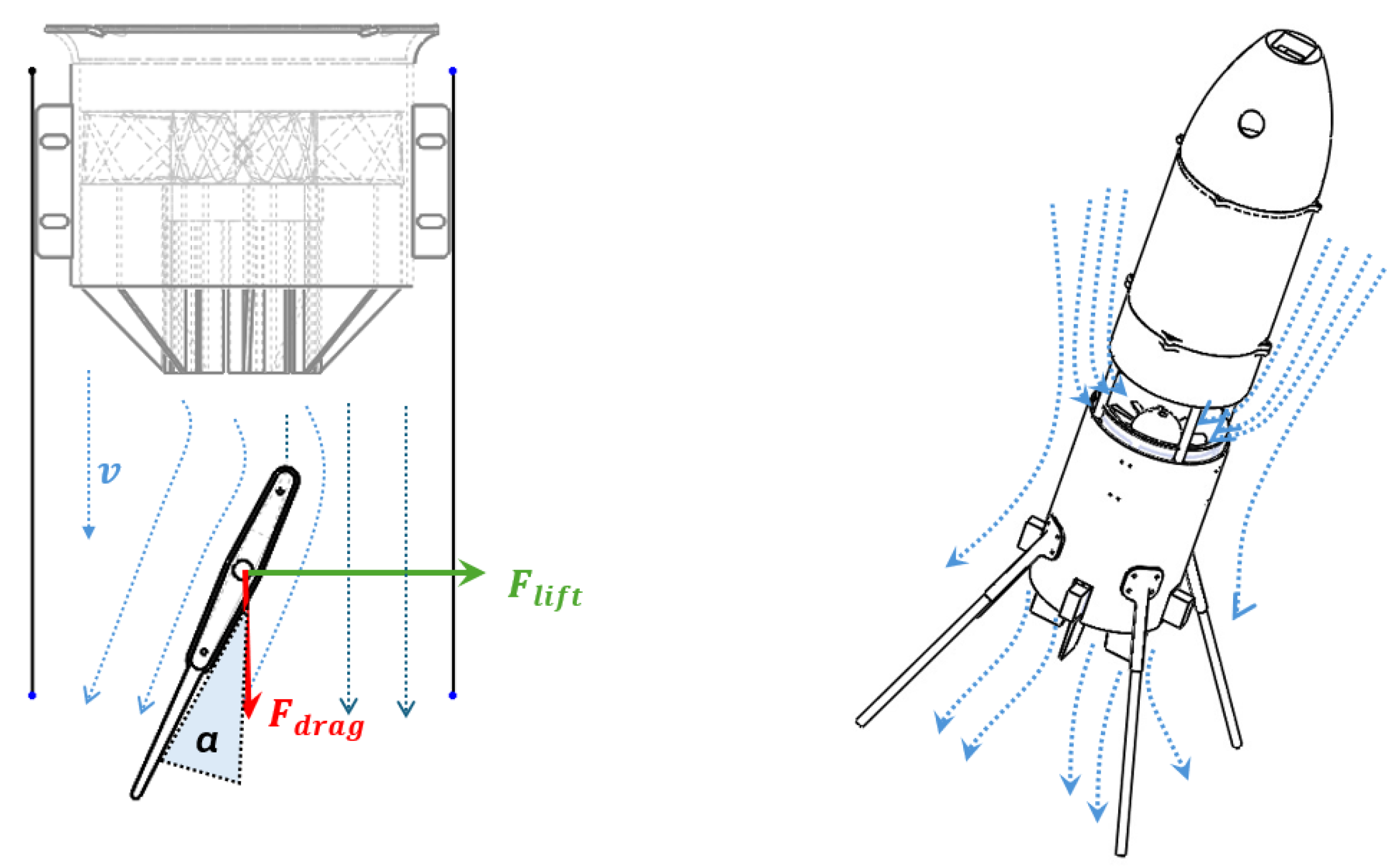
The first is the internalized EDF propulsion system. In conventional rotating-body UAVs the exposed propeller suffers efficiency degradation at high spin rates through asymmetric inflow and pronounced blade-tip vortices. Housing the rotor within a duct shields it from the rotating external free stream and aligns the flow through internal stators, mitigating tip losses and producing a thrust vector aligned with the principal body axis ; it also removes the exposed rotor, improving safety in confined or hazard-prone spaces [15]. The second is the use of aerodynamic fins for passive and active stabilization. Immersed in the ducted-fan exhaust, each fin experiences a high local relative velocity from the axial jet whenever the fan runs, even in a stationary, non-spinning hover, so it generates substantial forces without any forward translational speed or body spin. When the body does rotate, the spin adds a further contribution: at a radial distance from the spin axis the associated dynamic pressure is
where is the density of the air and is the spin rate, so the fins generate substantial forces without any forward translational speed, passively damping disturbances and when actively modulated, supplying control moments.
The third is gyroscopic stiffness through single-axis rotation: spinning the entire mass about the axial direction generates a large angular momentum, , which resists sudden changes in pitch and roll attitude and filters high-frequency disturbances. The fourth is the elimination of moving-mass actuation: rather than shifting internal masses to alter the center of gravity, as in many contemporary monocopters [12], the present design relies solely on the fin forces, removing heavy linear actuators and the associated mechanical complexity and latency. Taken together, these choices exploit a tightly coupled relationship in which the fan supplies lift and the reaction torque that drives the rotation, the fan exhaust provides the high-velocity airflow over the fins from which they generate the restoring and control moments for the non-spinning hover, while single-axis rotation, when present, adds gyroscopic stiffness.
Figure 2.
Aerodynamic operation of the fins. Left: a fin immersed in the ducted-fan exhaust of local velocity v and set at deflection (angle of attack) produces a lift (control/side) force and a drag force . The local flow velocity v is supplied primarily by the ducted-fan exhaust and is therefore present even at zero spin; when the body rotates it additionally includes the spin contribution of (1). The angle corresponds to the commanded fin deflection . Right: exhaust streamlines over the rotating airframe.
Figure 2.
Aerodynamic operation of the fins. Left: a fin immersed in the ducted-fan exhaust of local velocity v and set at deflection (angle of attack) produces a lift (control/side) force and a drag force . The local flow velocity v is supplied primarily by the ducted-fan exhaust and is therefore present even at zero spin; when the body rotates it additionally includes the spin contribution of (1). The angle corresponds to the commanded fin deflection . Right: exhaust streamlines over the rotating airframe.
The four fins are arranged as two orthogonal, opposing pairs. One pair governs the roll axis, supplying both the restoring moment that stabilizes roll and the control moment that commands it; the orthogonal pair governs the pitch axis in the same dual role. Yaw is controlled by deflecting all four fins together in a common rotational sense, which turns the swirling exhaust flow to produce a moment about the thrust axis. This common-mode deflection also performs an essential second function: a single ducted fan produces a reaction torque that would otherwise spin the body about its own axis, and the coordinated deflection of all four fins redirects the flow to counteract this torque, providing the anti-torque function that a single-rotor vehicle requires. The take-off mass is constrained to below to keep the platform suitable for confined-space and indoor operation and to limit impact energy; the selected , six-cell EDF provides approximately of maximum thrust, giving a thrust-to-weight ratio above two at the full take-off weight and ample authority for vertical take-off, hover, and rapid attitude correction.
3.2. Reference Frames, States, and Generalized Coordinates
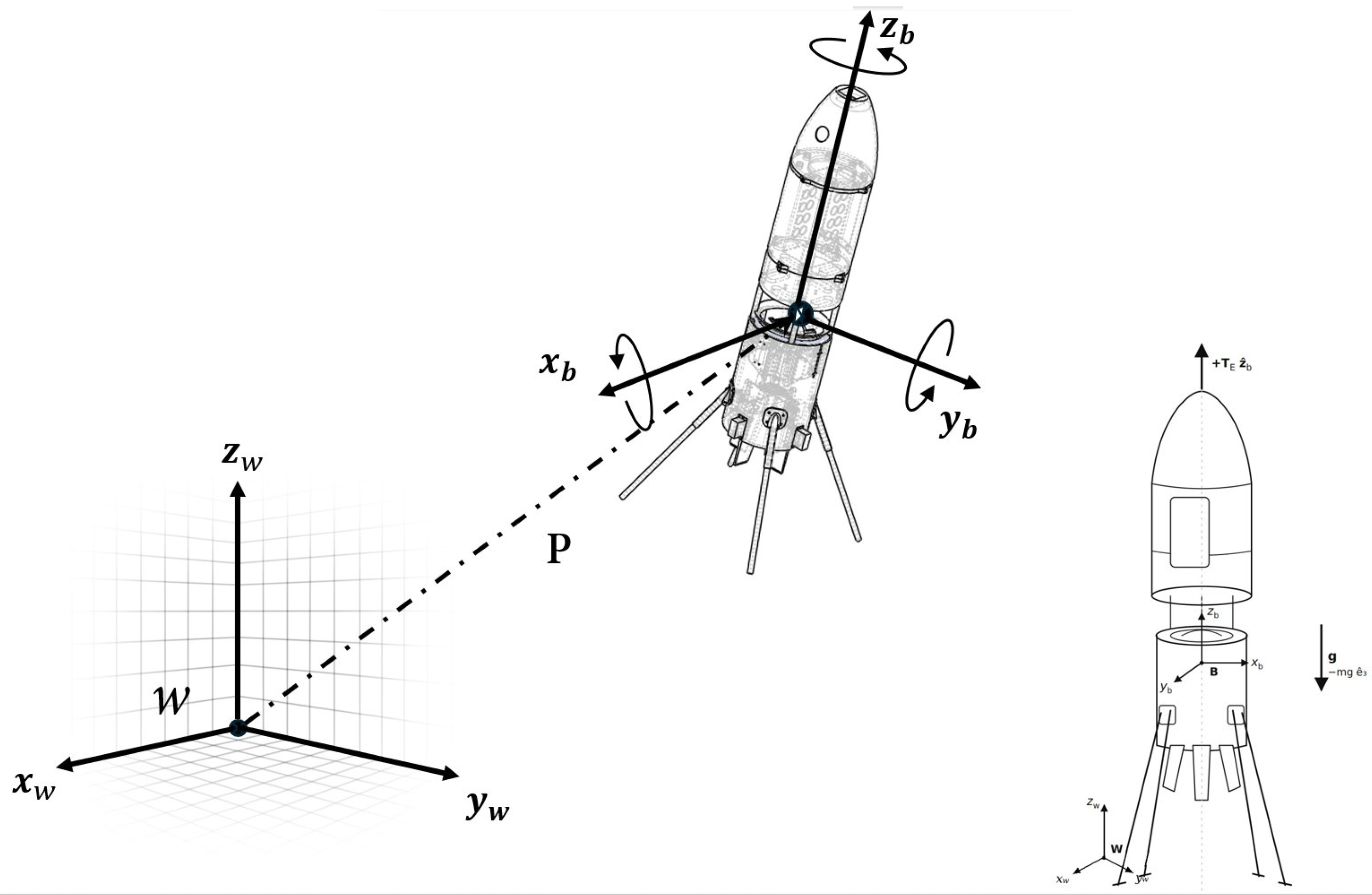
Two right-handed frames are used, the inertial (world) frame is fixed to the ground with pointing up. The body frame is fixed to the airframe at its center of mass, with aligned with the fan’s axis of rotation and thrust and aligned with the two fin pairs. The configuration is described by the generalized coordinate vector together with the body angular velocity ,
where is the position of the center of mass in , collects the Z–Y–X Tait–Bryan angles (roll , pitch , yaw ), and are the body-frame angular rates. The total mass is m; the inertia is characterized by the transverse moment and the axial (spin-axis) moment , with for the oblate airframe established in Section 3.8.
Figure 3.
Reference frames and free-body diagram of the monocopter. The inertial (world) frame is fixed to the ground with up; the body frame is fixed at the center of mass with along the fan thrust and spin axis, about which the airframe rotates. The vector is the center-of-mass position . Right: the body-axis thrust and the gravitational force acting on the airframe.
Figure 3.
Reference frames and free-body diagram of the monocopter. The inertial (world) frame is fixed to the ground with up; the body frame is fixed at the center of mass with along the fan thrust and spin axis, about which the airframe rotates. The vector is the center-of-mass position . Right: the body-axis thrust and the gravitational force acting on the airframe.
3.3. Attitude Kinematics
A vector expressed in is mapped to by the rotation matrix ,
where and . The body rates and the Tait–Bryan rates are related by the transformation matrix ,
The inverse is singular at , the gimbal-lock limitation inherent to the Euler-angle parameterization. Because the controlled vehicle holds a near-upright attitude, remains small and this singularity is not encountered in normal operation; it is noted here as a known limitation of the representation, and an attitude estimator tailored to the all-rotating regime [11] is one route to relaxing it.
3.4. Energy Formulation and the Lagrangian
The equations of motion follow from the Lagrangian , the difference of the total kinetic and potential energies. The kinetic energy combines translational and rotational parts,
where is the inertia tensor. The airframe is mass-symmetric about its principal axes, so the products of inertia are negligible, and it is designed as a body of revolution about , so the transverse inertias are equal:
Substituting the kinematic relation (4) casts the rotational kinetic energy in terms of the Euler-angle rates,
which defines the symmetric, positive-definite inertial matrix in the Euler-angle domain. With up, the gravitational potential is , so the complete Lagrangian is
The dynamics follow from the Euler–Lagrange equation applied to the generalized coordinates,
where collects the non-conservative generalized forces and moments. Because the Lagrangian separates into independent positional and angular parts, evaluating (9) for and for yields the translational and rotational dynamics in turn.
3.5. Translational Dynamics
Evaluating the Euler–Lagrange equation for the positional coordinates, with and , gives
where , is the ducted-fan thrust along , and collects the comparatively small aerodynamic forces on the fins and body. The thrust acts purely along the body axis, so its world-frame components are those of the third column of . Neglecting relative to the thrust and expanding component-wise,
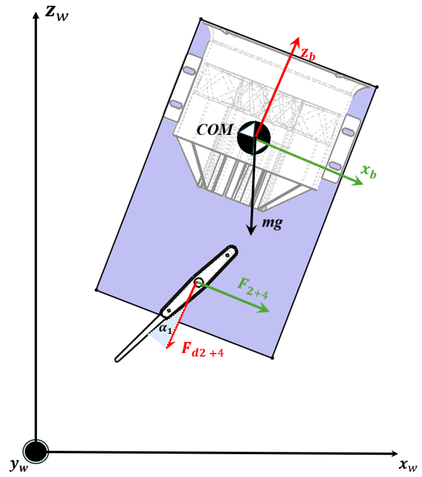
Figure 4.
Translation through attitude tilt. Tilting the body so that the thrust axis departs from the vertical gives the body-axis thrust a horizontal component, as in (11)–(13); the weight acts at the center of mass (COM). The force is the combined lift (control) force of fin pair 2 and 4 deflected at angle , with associated drag , which produces the moment that tilts the airframe. World frame ; body axes .
Figure 4.
Translation through attitude tilt. Tilting the body so that the thrust axis departs from the vertical gives the body-axis thrust a horizontal component, as in (11)–(13); the weight acts at the center of mass (COM). The force is the combined lift (control) force of fin pair 2 and 4 deflected at angle , with associated drag , which produces the moment that tilts the airframe. World frame ; body axes .
At an upright attitude () the horizontal accelerations vanish and (13) reduces to the hover condition . Horizontal motion is available only by tilting the body so that the thrust vector acquires a horizontal component; the monocopter has no means of translating other than redirecting its single thrust vector, accomplished by the fins through the attitude dynamics derived next. The translational and rotational subsystems are therefore coupled, with attitude driving position.
3.6. Rotational Dynamics
Evaluating the Euler–Lagrange equation for the angular coordinates and applying the chain rule to the configuration-dependent inertial matrix yields the manipulator form [22]
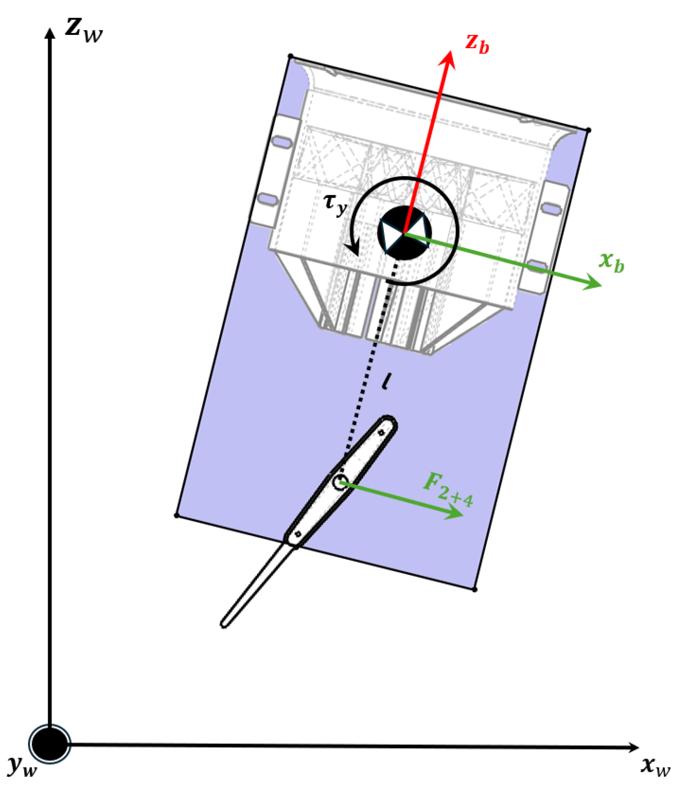
in which is the Coriolis and centripetal matrix and is the generalized torque mapped from the body-frame torque .
Figure 5.
Generation of a control moment. The lift force of fin pair 2 and 4, acting at the moment arm l (the fin radial offset ) from the center of mass, produces the pitch torque about the body y-axis; the orthogonal pair produces in the same way. These are the body-frame control moments that drive the rotational dynamics of (18)–(19). World frame ; body axes .
Figure 5.
Generation of a control moment. The lift force of fin pair 2 and 4, acting at the moment arm l (the fin radial offset ) from the center of mass, produces the pitch torque about the body y-axis; the orthogonal pair produces in the same way. These are the body-frame control moments that drive the rotational dynamics of (18)–(19). World frame ; body axes .
Carrying out the product gives
At the upright attitude this reduces to , recovering the principal inertias as expected. The entries of follow from through the Christoffel symbols of the first kind,
which, evaluated symbolically for in (15), yields the full Coriolis and centripetal matrix
whose nonzero entries, writing , are
Its physical content is clearest in the equivalent body-frame statement of (14), obtained from Euler’s rigid-body equations . For the axisymmetric inertia of (6) these read
The cross-coupling terms and are the gyroscopic moments. In a non-spinning vehicle these are products of two small rates and may be neglected near hover; here the spin rate r is large and continuous, so they dominate the transverse dynamics and couple the roll and pitch axes through the spin. This coupling is the defining dynamic feature of the monocopter and underlies the stability analysis of Section 3.8.
3.7. Generalized Forces and Spin Equilibrium
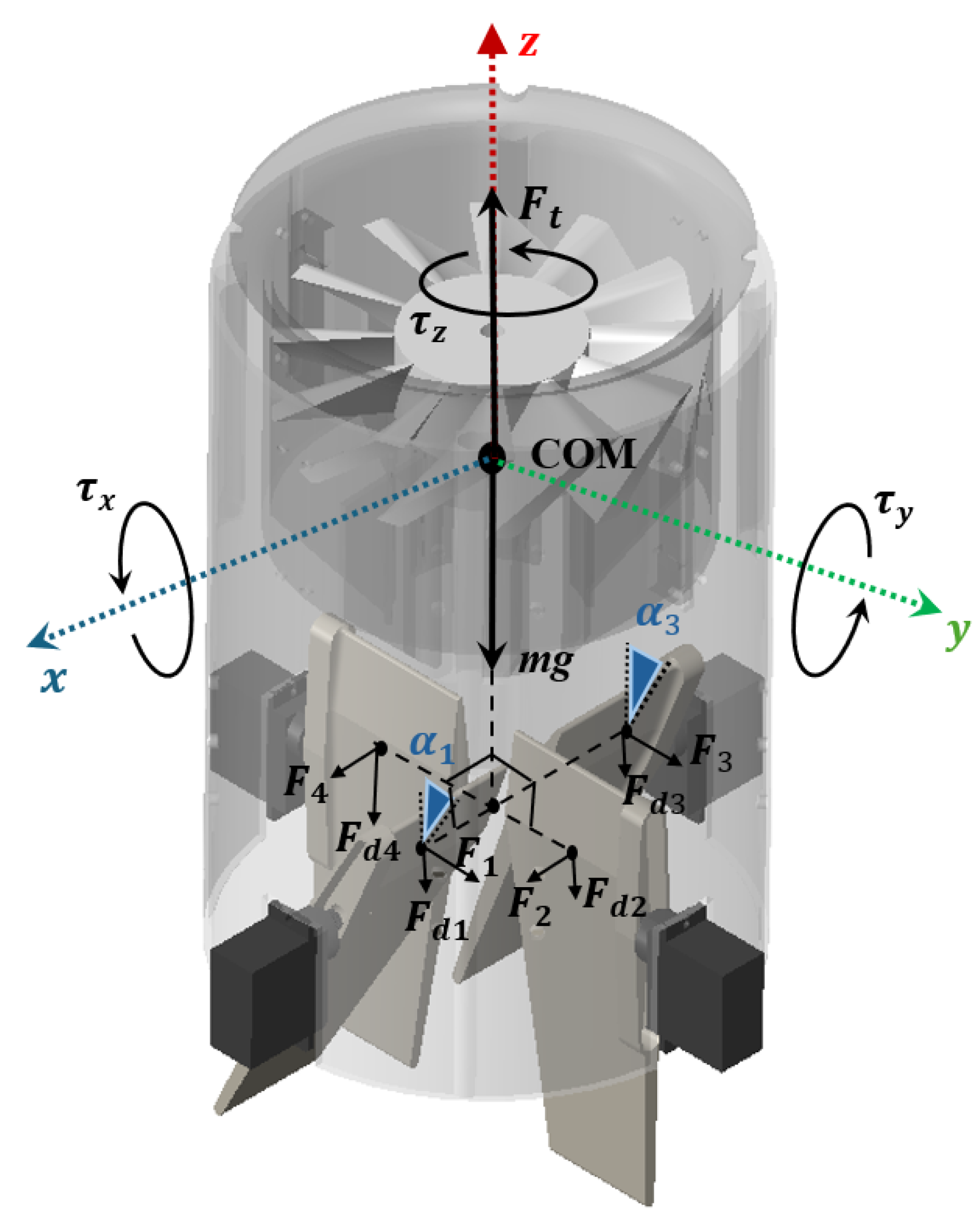
The body-frame torques are produced by the four fins acting in the fan’s exhaust and by the fan’s own reaction torque. Deflecting one opposing fin pair produces a roll moment , the orthogonal pair a pitch moment , and a common deflection of all four a yaw moment; superimposed on these is the continuous reaction torque of the single fan about , which drives the rotation of the airframe [14,21]. About the spin axis the net yaw torque is therefore
where is the lumped aerodynamic drag-torque coefficient of the rotating body and fins, and is the controllable yaw contribution of the fins. In the open-loop regime () the airframe accelerates in yaw until the fan’s reaction torque is balanced by aerodynamic drag, , defining the steady-state hover spin rate
Vertical equilibrium is set independently by the thrust, from (13) with the spin axis vertical. Equation (22) shows that altitude and spin are coupled through the fan: a change in thrust to climb or descend also changes the reaction torque and hence the equilibrium spin rate, a coupling the controller must accommodate.
Figure 6.
Free-body diagram of forces and moments in the body frame . The ducted fan produces the axial thrust (the thrust in the text) and a reaction torque about the spin axis that, together with the fins, sets the net yaw moment of (21); the weight acts at the center of mass (COM). Each fin i generates a lift force at deflection and a drag force ; differential action of the opposing pairs yields the roll and pitch moments , while common-mode action yields and cancels the fan reaction torque.
Figure 6.
Free-body diagram of forces and moments in the body frame . The ducted fan produces the axial thrust (the thrust in the text) and a reaction torque about the spin axis that, together with the fins, sets the net yaw moment of (21); the weight acts at the center of mass (COM). Each fin i generates a lift force at deflection and a drag force ; differential action of the opposing pairs yields the roll and pitch moments , while common-mode action yields and cancels the fan reaction torque.
3.8. Stability: The Oblate-Inertia Condition
Consider a small attitude disturbance about the spin equilibrium, with the body spinning at and the transverse rates small. Linearizing (18)–(19) and adding the transverse aerodynamic damping supplied by the fins gives the coupled transverse system
The off-diagonal terms describe gyroscopic precession: a disturbance about one transverse axis is converted into motion about the orthogonal axis at the nutation frequency
a ninety-degree phase relationship between roll and pitch. With no damping () the eigenvalues are purely imaginary, , and the vehicle precesses indefinitely; the spin confers stiffness but not asymptotic stability, and the fins supply the damping that dissipates the nutation energy. For this dissipation to drive the disturbance to zero rather than amplify it, the spin must occur about the axis of maximum inertia. This is the major-axis rule for the directional stability of an energy-dissipating spinning body [23]: sustained, stable rotation requires the spin-axis inertia to exceed the transverse inertia, so that the vehicle is an oblate symmetric top,
Equation (25) is the stability condition for the vehicle’s rotation about its own axis and is a direct constraint on the mass layout: the heavy components—the fan, battery, and avionics—must be distributed radially outward rather than stacked along the axis, so that is made large relative to [21]. A vehicle that is too slender, with approaching , loses gyroscopic stiffness and becomes prone to an unrecoverable tumble. The oblate condition therefore governs the stability of the vehicle’s rotation about its own axis; keeping the vehicle upright and hovering is the separate task of the fins, which additionally cancel the reaction torque to suppress the spin in controlled flight.
3.9. Linear Model for Control
For control design the nonlinear dynamics are linearized about the spin equilibrium by evaluating the Jacobians,
with and . The transverse block of is precisely (23), so the gyroscopic coupling and fin damping carry directly into the linear model on which the stabilizing controller acts; the translational block follows from linearizing (11)–(13), in which attitude perturbations enter as horizontal forcing. In the closed-loop regime the fins are commanded under feedback from the onboard inertial measurement unit to oppose the gyroscopic precession and regulate the attitude.
3.10. Flight-Control Software and Control Allocation
Attitude stabilization is implemented on a commercial flight-control stack running the open-source INAV firmware [24], configured so that the four aerodynamic fins serve as the control effectors while the ducted fan provides thrust alone. State estimation relies on a six-axis inertial measurement unit comprising a microelectromechanical gyroscope and accelerometer, supplemented by a barometric pressure sensor for altitude; no magnetometer is fitted, consistent with the indoor objective of regulating attitude rather than holding a compass course. The control loop executes at a period of (). Because the rotating fan and airframe inject vibration into the inertial measurement, the gyroscope signal is conditioned by a dynamic low-pass filter whose cutoff scales with throttle between 85 and , together with an adaptive notch that tracks and rejects the dominant vibration tone, preserving the attitude-rate bandwidth while suppressing structural content that would otherwise be differentiated by the derivative term.
Stabilization is performed in the self-leveling (angle) mode. On each control axis the corrective demand is formed by the standard proportional–integral–derivative law,
in which e is the error between commanded and measured attitude on that axis, u is the resulting roll, pitch, or yaw demand subsequently distributed to the fins, and are the per-axis gains of Table 1; the firmware evaluates the discrete-time equivalent of (27) at the loop rate. The proportional term opposes the instantaneous error, the derivative term supplies damping, and the integral term removes steady-state offset. The roll and pitch axes share the same gains, reflecting the transverse symmetry of the airframe, while the yaw axis is tuned more conservatively because the fin authority about the spin axis is comparatively low.
The mapping from the stabilizer outputs to the physical actuators is set by two mixers. In the motor mixer, the single fan output carries the collective throttle command with no roll, pitch, or yaw contribution, reproducing the modeling assumption of Section 3.5 in which the thrust acts purely along and every control moment is supplied by the fins. The servo mixer realizes the fin allocation of Table 2: fins 1 and 4 form one opposing pair and receive the roll demand with opposite sign, so their differential deflection produces ; fins 2 and 3 form the orthogonal pair and produce in the same manner; the yaw demand is applied to all four fins with the same sign, so a common-mode deflection produces while simultaneously countering the fan reaction torque.
To illustrate the operation of the stabilization loop on a traceable model, the rotational dynamics are specialized to the non-spinning condition by setting in (18)–(19), which removes the gyroscopic cross-terms so that the transverse axes decouple, each reducing to a single-axis rigid body and . Writing one such axis in terms of its attitude , adding the aerodynamic damping supplied by the fins and the linear fin-torque relation in the deflection , the plant is
or, as a transfer function from fin deflection to attitude,
With the representative parameters of Table 3, (29) becomes , with poles at and . The integrator at the origin expresses that, absent feedback, a deflected fin drives the body into continuous rotation; arresting this motion is precisely the role of the stabilization loop. These values are illustrative, used to exhibit the control law; the measured inertia and aerodynamic coefficients are the subject of the experimental identification reserved for future work.
In accordance with MDPI policy, the authors disclose that a generative-AI assistant was used to support drafting, editing, and the assembly and formatting of this manuscript and its bibliography; the authors reviewed and edited all output and take full responsibility for the content. TODO(Sam): confirm tool name/version and exact scope.
4. Results
4.1. Realized Airframe and Mass Distribution
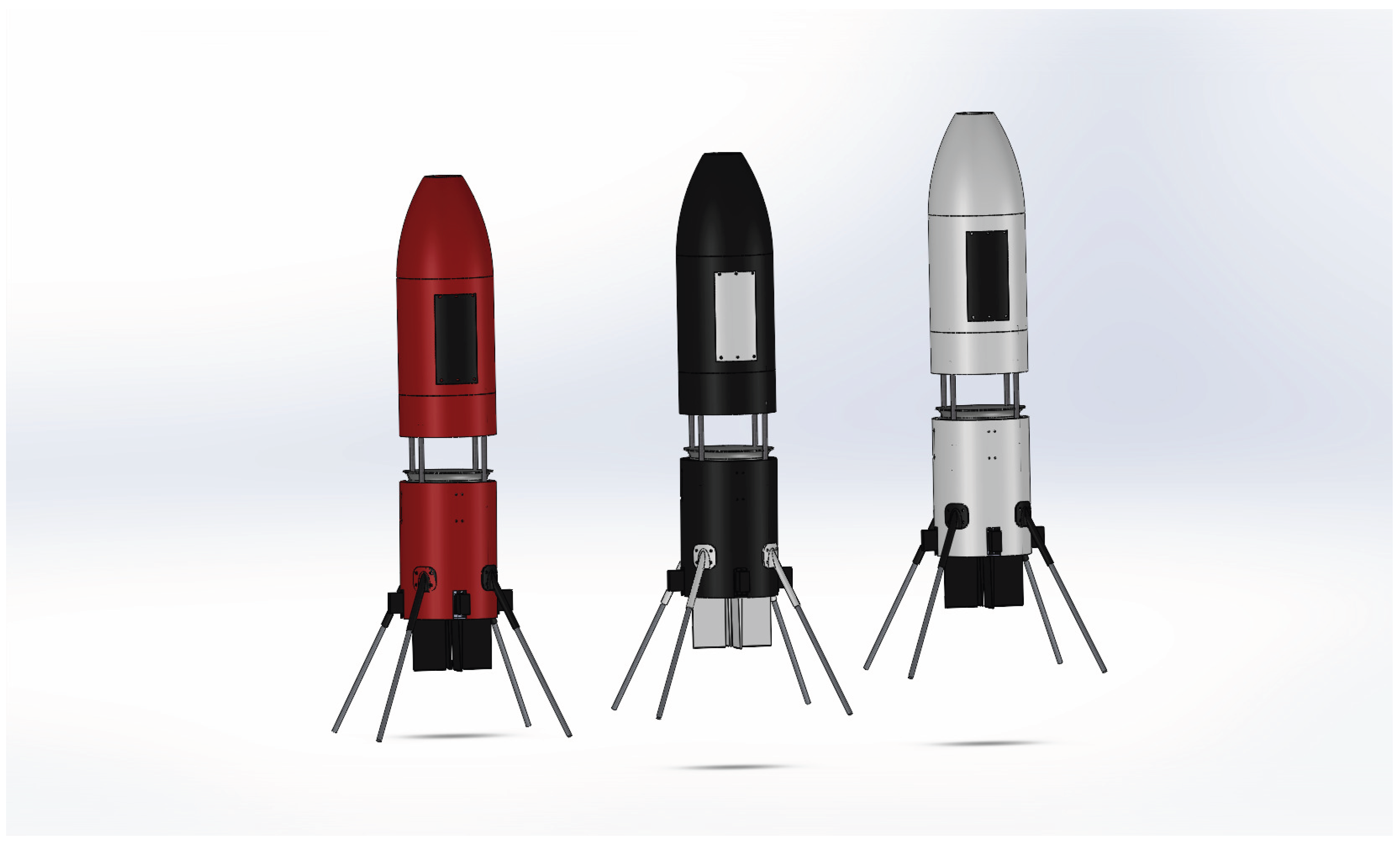
The oblate-inertia requirement (25) governs the physical layout of the airframe. In the realized model (Figure 7) the heavy internal components the avionics stack, the lithium-polymer battery, and the electronic speed controller are distributed radially around the central housing rather than stacked along the spin axis, so that the axial inertia exceeds the transverse inertia. The electric ducted fan is integrated into the core of the fuselage; this internalized arrangement removes the exposed-rotor tip vortices and contact hazards of a conventional monocopter, and the fan shroud doubles as the primary structural spine, providing the mounting points for the four aerodynamic fins, which are spaced at ninety-degree intervals and each driven through a servo linkage. The underground platform was developed through five successive prototypes; the fifth and final configuration is the one analyzed and indoor-tested here.
4.2. Open- and Closed-Loop Dynamic Response of
The control behavior is characterized on the single-axis reduction of (29), obtained by setting in (18)–(19) and adding the aerodynamic fin damping, which gives with poles at and . Figure 8 contrasts its open- and closed-loop response, where is the single-axis attitude and the commanded fin deflection.
In open loop (Figure 8, left), a constant fin deflection is applied with no feedback. The attitude does not settle to a fixed angle but grows continuously, diverging as a direct consequence of the pole at : absent feedback, a steady fin deflection drives the body into continuous rotation rather than a bounded attitude. This is the open-loop behavior that the stabilization loop must overcome.
In closed loop (Figure 8, right), the same plant is regulated by the PID law of (27). From a initial disturbance, the controller commands a corrective fin deflection that saturates at its limit while the error is large, then relaxes as the attitude is brought back; the attitude crosses zero, exhibits a single modest undershoot of roughly , and settles to the commanded zero within about four seconds, with the integral action removing the steady-state offset. The bounded actuator effort and the smooth, well-damped return confirm that the proportional, derivative, and integral terms together stabilize the otherwise divergent plant.
This result illustrates the qualitative operation of the control law on the reduced plant the conversion of an attitude error into a corrective fin deflection through the mixer of Table 2 and the resulting return to the commanded attitude and is not a quantitative prediction of the full vehicle response, whose measured inertia and aerodynamic coefficients are the subject of the experimental identification reserved for future work.
These responses illustrate the qualitative operation of the control law on the reduced plant the conversion of an attitude error into a corrective fin deflection through the mixer of Table 2 and the resulting return to the commanded attitude and are not a quantitative prediction of the full vehicle response, whose measured inertia and aerodynamic coefficients are the subject of the experimental identification reserved for future work.
4.3. Yaw-Rate Spin-Up and Hover Equilibrium
The open-loop yaw dynamics of (20) govern how the airframe reaches its operating spin rate. Driven by the fan reaction torque and opposed by the aerodynamic drag of the rotating body and fins (21), the yaw rate r accelerates from rest and asymptotically plateaus when the two balance, defining the steady-state hover spin rate of (22). Figure 9 shows this behavior: r rises steeply from zero, its slope tapering as drag grows quadratically, and settles at . This equilibrium is the operating point about which the transverse dynamics are linearized; through the gyroscopic term it sets the nutation frequency of (24) and therefore the stability margin examined in the following subsections.
4.4. Unstable Transverse Response
When the oblate-inertia condition is not met with sufficient margin, the same transverse mode becomes divergent rather than damped. Figure 10 shows the body rates p and q under such a configuration: a small perturbation is amplified cycle on cycle, the nutation envelope expanding instead of decaying until the transverse rates reach magnitudes of order , far beyond any recoverable attitude. Physically, this is the failure mode guarded against by the major-axis rule for an energy-dissipating spinning body [23]: stable rotation requires the spin to occur about the axis of maximum inertia, and when that condition is violated the fin and structural dissipation act to grow the nutation rather than damp it. The contrast between Figure 11 and Figure 10 is the central design constraint of the platform: the oblate margin must be established, and sized together with the fin damping, so that the vehicle remains on the stable side of this boundary throughout its operating spin range.
4.5. Stable Transverse Response to a Gust
With the airframe satisfying the oblate-inertia condition of (25), the transverse dynamics are passively stable. Figure 11 shows the body rates p and q (the two curves) following an impulsive transverse gust applied at . The gust excites both transverse axes, which respond with the ninety-degree phase relationship of the gyroscopic cross-coupling embodied in the off-diagonal terms of (23): energy is exchanged between the roll and pitch axes at the nutation frequency (24), so a disturbance about one axis appears as motion about the other a quarter cycle later. Because the spin occurs about the axis of maximum inertia, the four fins act as net aerodynamic dampers, and the nutation envelope decays to zero within a few seconds, returning the vehicle to a vertical orientation. This confirms that a well-conditioned oblate airframe recovers from transverse disturbances passively, without any active control input.
4.6. Indoor Flight Demonstration
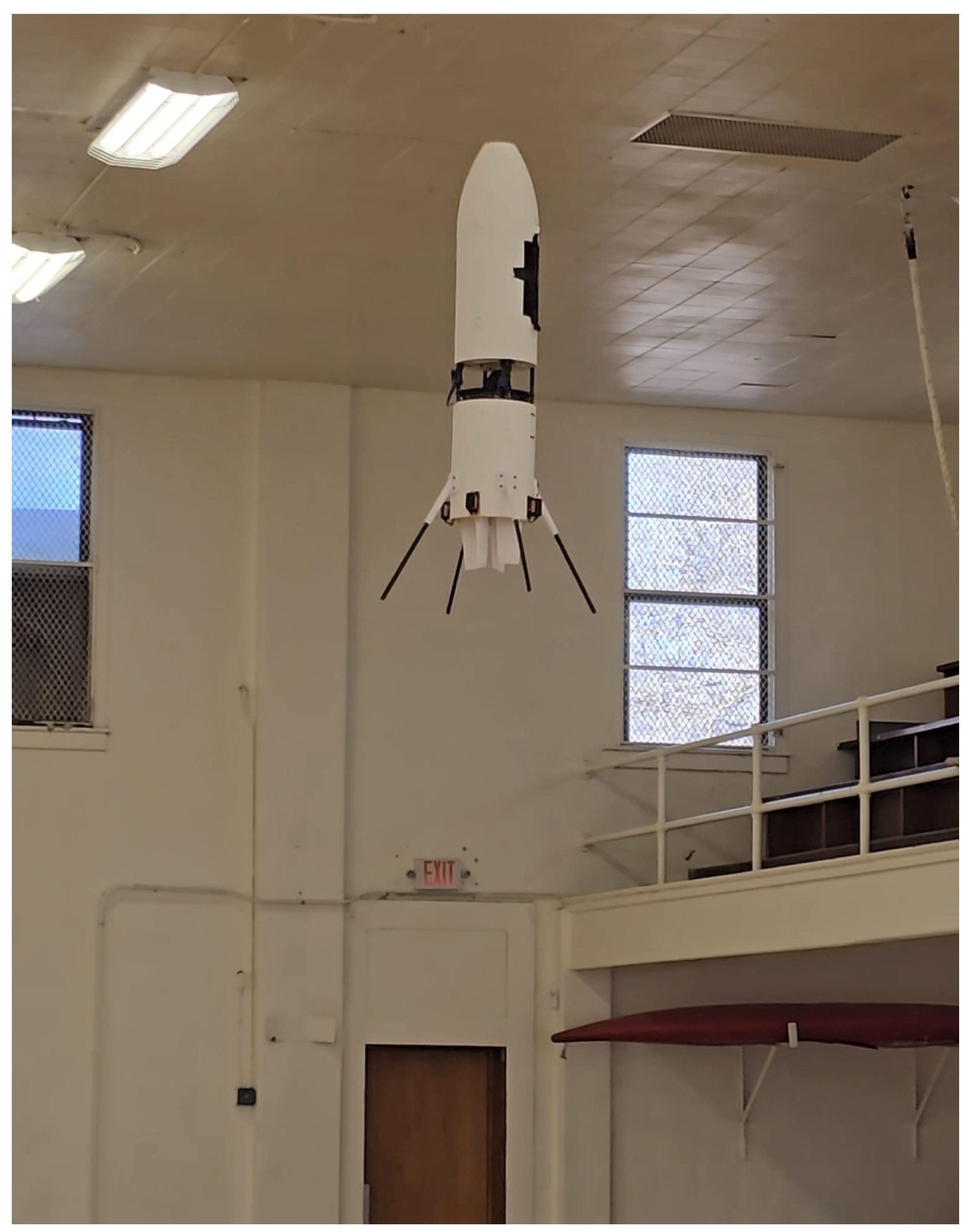
An initial indoor flight test was conducted as an exploratory, proof-of-concept characterization of the fabricated prototype. Under fin stabilization the vehicle hovered with a stable, upright attitude in a non-spinning, cruciform-type configuration, generating sufficient lift and holding its orientation without tumbling; this establishes a proof of concept for controlled hovering flight of the platform. Separately, and without the fins engaged, the airframe spins continuously about its axis under the fan reaction torque alone, the open-loop rotational behavior characterized in Section 4.3Section 4.4. The simultaneous spinning, fin-stabilized flight predicted by the model was not demonstrated here: continuous body spin and active upright stabilization were observed as separate behaviors, and their combination is reserved for future work. No outdoor, free, or sustained autonomous flight was attempted, and the demonstration is not a quantified performance evaluation.
Figure 12.
Indoor proof-of-concept demonstration: the fabricated monocopter hovering with a stable, upright attitude under fin stabilization (non-spinning, cruciform-type configuration). Continuous body spin under the fan reaction torque was observed separately, without the fins engaged.
Figure 12.
Indoor proof-of-concept demonstration: the fabricated monocopter hovering with a stable, upright attitude under fin stabilization (non-spinning, cruciform-type configuration). Continuous body spin under the fan reaction torque was observed separately, without the fins engaged.
5. Discussion
The model and the simulated response together identify the governing trade-off of the vehicle’s uncontrolled, spinning regime distinct from the controlled, non-spinning hover, which is stabilized actively by the fins. In that spinning regime, stability is provided not by a static restoring moment but by the gyroscopic stiffness of continuous rotation, quantified by the nutation frequency (24), while asymptotic return to the upright attitude is provided by the aerodynamic fin damping of (23). Because the gyroscopic term scales with the inertia difference and the spin rate , whereas the available fin damping scales with the fin area and the same dynamic pressure (1), the design must balance the two: when the spin axis is not the axis of maximum inertia the dissipation destabilizes the nutation and the vehicle tumbles (Figure 10), whereas with an adequate oblate margin the fins damp disturbances to zero (Figure 11). The oblate-inertia condition (25) is therefore necessary but not sufficient; it must be met with a margin matched to the fin authority. This is the rotating-body counterpart of the static-margin condition that governs conventional fixed-wing stability, and it ties the structural mass layout, the propulsion, and the aerodynamic design together as a single coupled problem.
Relative to the conference paper that this work extends [21], the present paper contributes the complete energy-based Euler–Lagrange derivation, including the configuration-dependent inertia matrix (15) and the full symbolic Coriolis matrix (17); the spin-equilibrium relation (22) and the oblate-inertia stability analysis with its nutation-frequency interpretation; the linearized transverse model (23) and the four-fin control allocation; the simulation-based dynamic-response characterization; and a broadened positioning within the single-wing and ducted-fan literature. Relative to the earlier coaxial platforms of the group, which achieved control through moving-mass actuation [12] or active thrust vectoring [13], the present design removes both the exposed rotor and the moving-mass and thrust-vectoring mechanisms, reducing the moving parts to the fan and four servo-driven fins.
Figure 13.
Rendered CAD model of the final monocopter airframe. The body comprises the lower ducted-fan housing, the upper avionics and payload section with a service access panel, and four landing legs; the heavy components are distributed radially within the body so that the axial inertia exceeds the transverse inertia, satisfying the oblate condition of (25)
Figure 13.
Rendered CAD model of the final monocopter airframe. The body comprises the lower ducted-fan housing, the upper avionics and payload section with a service access panel, and four landing legs; the heavy components are distributed radially within the body so that the axial inertia exceeds the transverse inertia, satisfying the oblate condition of (25)
The principal limitation follows directly from the scope. The experimental evidence is an indoor, exploratory characterization of a proof-of-concept prototype; it does not constitute a quantified performance evaluation, and no outdoor, free, or sustained autonomous flight is claimed. The aerodynamic coefficients and , the fin effectiveness , and the inertias and entering the model are design estimates rather than independently measured quantities, and the closed-loop study of Section 4.2 is illustrative. Active phase-locked cyclic control, instrumented tethered and free flight with systematic logging, and experimental identification of the model parameters against measured response are accordingly identified as the principal directions for future work, alongside an attitude estimator suited to the all-rotating regime [11].
6. Conclusions
An internally propelled, fin-stabilized monocopter was designed, modeled, and characterized. A single fully internalized electric ducted fan provides lift and the reaction torque that drives the rotation, and four aerodynamic fins immersed in the exhaust provide full three-axis control together with reaction-torque cancellation, without the moving-mass or thrust-vectoring mechanisms of earlier coaxial designs. A control-oriented dynamic model was derived from an energy-based Euler–Lagrange formulation, yielding the configuration-dependent inertia and Coriolis matrices and the equivalent body-frame equations whose gyroscopic coupling dominates the transverse dynamics; a stability analysis established the oblate-inertia condition that determines whether the vehicle’s natural rotation holds its spin axis or diverges into a tumble, relating it to the major-axis rule for energy-dissipating spinning bodies; and the model was linearized about the spin equilibrium for control. Simulation reproduced the deterministic hover spin equilibrium, the gyroscopic cross-coupling, and the fin-damped recovery of the spinning body, and an indoor proof-of-concept demonstration confirmed sustained rotation and passive stabilization of the fabricated prototype. The results indicate that an internally propelled, fin-stabilized monocopter is a mechanically simple, collision-tolerant alternative for compact rotary flight; the implementation of active phase-locked control, instrumented flight characterization, and experimental identification of the model parameters are identified as the principal future work.
References
- Briod, A.; Kornatowski, P.; Zufferey, J.C.; Floreano, D. A collision-resilient flying robot. J. Field Robot. 2014, 31, 496–509. [Google Scholar]
- Lentink, D.; Dickson, W.B.; van Leeuwen, J.L.; Dickinson, M.H. Leading-edge vortices elevate lift of autorotating plant seeds. Science 2009, 324, 1438–1440. [Google Scholar] [CrossRef] [PubMed]
- Ulrich, E.R.; Humbert, J.S.; Pines, D.J. Pitch and heave control of robotic samara micro air vehicles. J. Aircr. 2010, 47, 1290–1299. [Google Scholar] [CrossRef]
- Ulrich, E.R.; Pines, D.J.; Humbert, J.S. From falling to flying: The path to powered flight of a robotic samara nano air vehicle. Bioinspiration Biomim. 2010, 5, 045009. [Google Scholar] [CrossRef] [PubMed]
- Pines, D.J.; Humbert, J.S.; Hubbard, J.E.; Ulrich, E.R.; Faruque, I.; Grauer, J.A. Control model for robotic samara: Dynamics about a coordinated helical turn. J. Guid. Control Dyn. 2010, 33, 1921–1927. [Google Scholar] [CrossRef]
- Kellas, A. The Guided Samara: Design and Development of a Controllable Single-Bladed Autorotating Vehicle. Master’s thesis, Massachusetts Institute of Technology, 2007. [Google Scholar]
- Win, S.K.H.; Win, L.S.T.; Sufiyan, D.; Foong, S. Design and control of the first foldable single-actuator rotary wing micro aerial vehicle. Bioinspiration Biomim. 2021, 16, 066019. [Google Scholar] [CrossRef]
- Bhardwaj, H.; Cai, X.; Win, S.K.H.; Foong, S. Design, modeling and control of a two flight mode capable single wing rotorcraft with mid-air transition ability. IEEE Robot. Autom. Lett. 2022, 7, 11720–11727. [Google Scholar] [CrossRef]
- Moon, J.S.; Kim, C.; Youm, Y.; Bae, J. UNI-Copter: A portable single-rotor-powered spherical unmanned aerial vehicle (UAV) with an easy-to-assemble and flexible structure. J. Mech. Sci. Technol. 2018, 32, 2289–2298. [Google Scholar] [CrossRef]
- Cai, X.; Win, S.K.H.; Foong, S. Design and optimization of a samara-inspired lightweight monocopter for extended endurance. IEEE Robot. Autom. Lett. 2025, VERIFY volume/number/pages on final publication. [Google Scholar] [CrossRef]
- Tong, S.; Shi, Z.; Sun, Z.; Wang, L. Attitude estimation for an all-rotating monocopter through attitude decomposition and MARG sensor fusion. Aerosp. Sci. Technol. 2024, 154, 109511. [Google Scholar] [CrossRef]
- Nguyen, D.T.A.; Maimako, S.; Hassanalian, M. Modeling and Control of a Coaxial Monocopter via Moving Mass Actuation. Proc. AIAA Aviat. Forum ASCEND. 2025, 2025, 3083. [Google Scholar] [CrossRef]
- Maimako, S.; Opoku, J.; Nguyen, D.T.A.; Hassanalian, M. Design and Experimental Validation of a Next-Generation Coaxial Monocopter. In Proceedings of the AIAA SCITECH 2026 Forum, 2026; p. 2083. [Google Scholar] [CrossRef]
- Hrishikeshavan, V.; Sirohi, J.; Tishchenko, M.; Chopra, I. Design, development, and testing of a shrouded single-rotor micro air vehicle with antitorque vanes. J. Am. Helicopter Soc. 2011, 56, 12008. [Google Scholar] [CrossRef]
- Deng, S.; Wang, S.; Zhang, Z. Aerodynamic performance assessment of a ducted fan UAV for VTOL applications. Aerosp. Sci. Technol. 2020, 103, 105895. [Google Scholar] [CrossRef]
- Yin, Z.; Pei, H. A ducted fan UAV for safe aerial grabbing and transfer of multiple loads using electromagnets. In Proceedings of the 2024 IEEE/RSJ International Conference on Intelligent Robots and Systems (IROS); IEEE, 2024; pp. 10342–10349. [Google Scholar]
- Ryals, A.D.; Alibani, M.; Lantermo, G.; Menolotto, M.; Maugeri, S.; Pollini, L. A modular 3D-printed ducted-fan platform for advanced autonomy research: From design to flight test. Drones 2026, 10, 165. [Google Scholar] [CrossRef]
- Luo, Y.; He, Y.; Xu, B.; Ai, T.; Qian, Y.; Zhang, Y. Numerical simulation and analysis of a ducted-fan drone hovering in confined environments. Adv. Aerodyn. 2024, 6, 18. [Google Scholar] [CrossRef]
- Luo, Y.; He, Y.; Ai, T.; Xu, B.; Qian, Y.; Zhang, Y. Numerical study on dynamic performance of a ducted fan moving in proximity to ground and ceiling. Phys. Fluids 2024, 36, 115151. [Google Scholar] [CrossRef]
- Luo, Y.; Ai, T.; He, Y.; Xu, B.; Qian, Y.; Zhang, Y. Numerical investigation on unsteady characteristics of ducted fans in ground effect. Chin. J. Aeronaut. 2023, 36, 79–95. [Google Scholar] [CrossRef]
- Maimako, S.; Nguyen, D.T.A.; Abdullahi, F.; Hassanalian, M. Design and Analysis of an EDF-Driven Monocopter UAV With Fin-Based Stabilization. In Proceedings of the AIAA AVIATION Forum, 2026. [Google Scholar] [CrossRef]
- Luukkonen, T. Modelling and Control of Quadcopter. Independent research project in applied mathematics, Aalto University, School of Science, Espoo, Finland, 2011. [Google Scholar]
- Hughes, P.C. Spacecraft Attitude Dynamics; Dover Publications: Mineola, NY, 2004. [Google Scholar]
- INAV Flight Control. INAV: Navigation-Capable Flight Control Software. 2023. Available online: https://github.com/iNavFlight/inav.
Figure 1.
CAD assembly model of the single-EDF, four-fin monocopter configuration, with the ducted fan housed centrally and the four fins distributed at ninety-degree intervals; heavy components are placed radially to satisfy the oblate condition .
Figure 1.
CAD assembly model of the single-EDF, four-fin monocopter configuration, with the ducted fan housed centrally and the four fins distributed at ninety-degree intervals; heavy components are placed radially to satisfy the oblate condition .
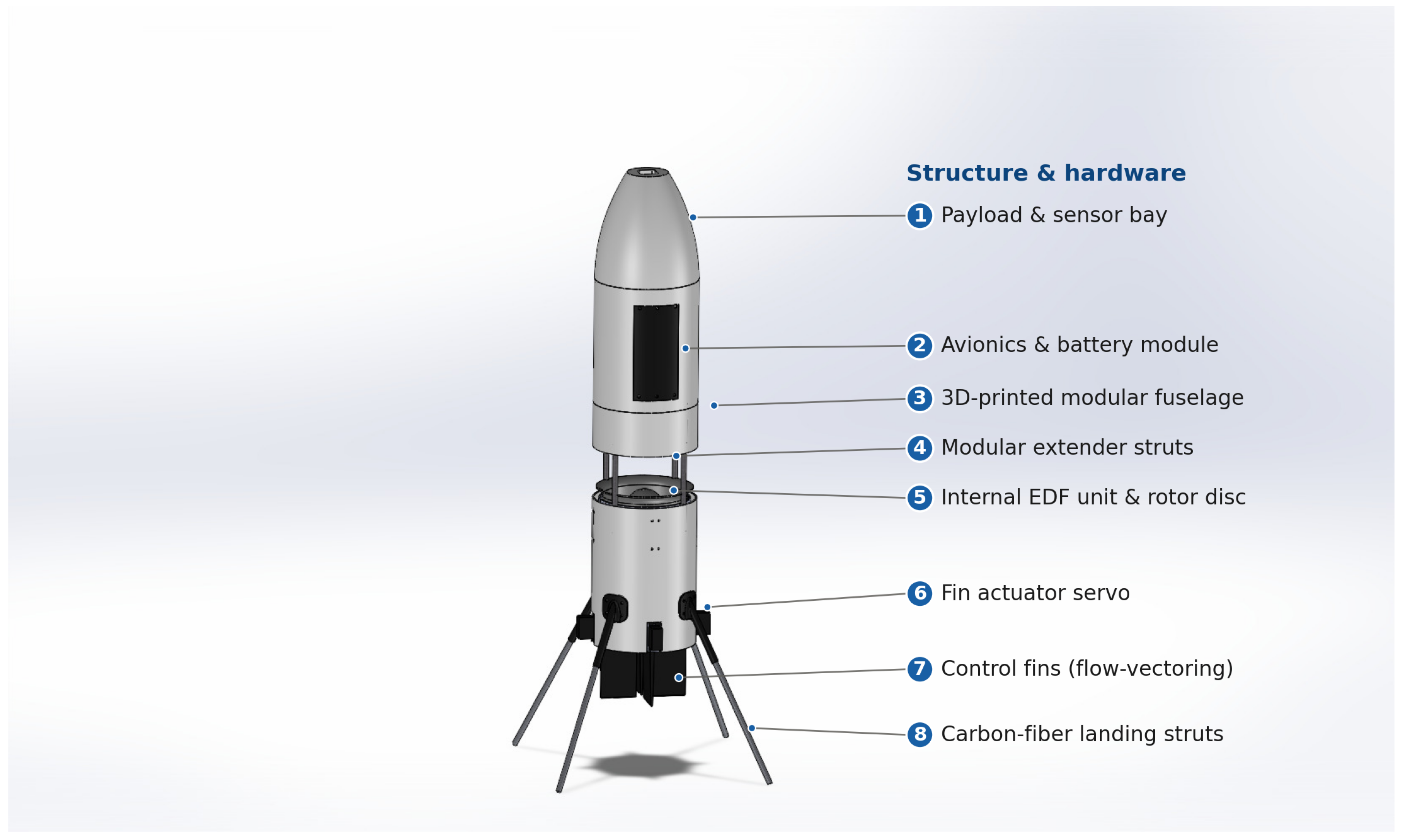
Figure 7.
Evolution of the EDF monocopter across successive prototypes: from early 3D-printed ducted shells (top left), through carbon-fiber airframes and an open bench-test frame carrying the four stabilizing fins and their servos (top right), to the integrated airframe (bottom left) and its CAD model (bottom center). The final configuration is the one modeled and indoor-tested in this work.
Figure 7.
Evolution of the EDF monocopter across successive prototypes: from early 3D-printed ducted shells (top left), through carbon-fiber airframes and an open bench-test frame carrying the four stabilizing fins and their servos (top right), to the integrated airframe (bottom left) and its CAD model (bottom center). The final configuration is the one modeled and indoor-tested in this work.
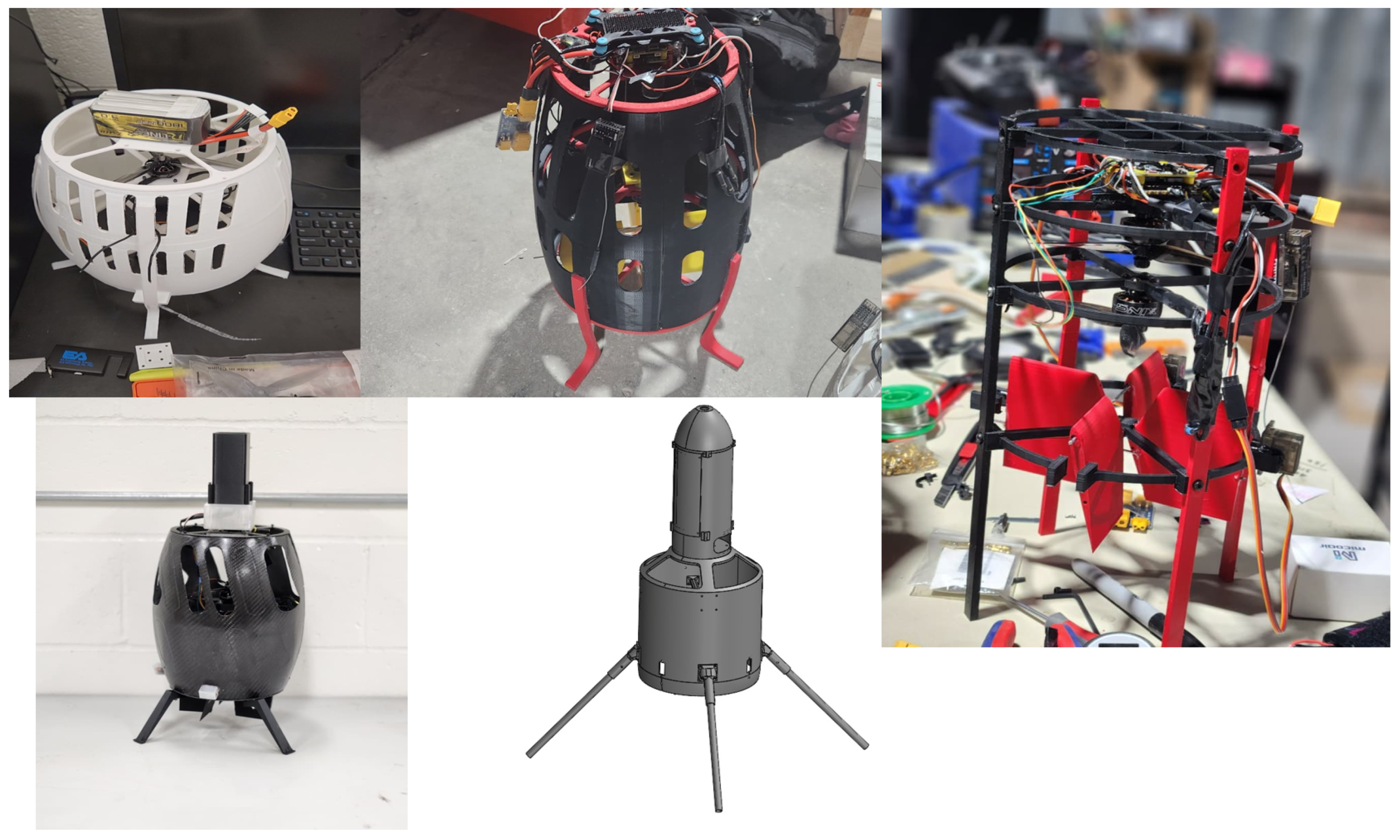
Figure 8.
Response of the illustrative single-axis plant of (29). Left: under a constant fin deflection with no feedback, the attitude diverges, reflecting the pole at . Right: closed under the PID law of (27), a initial disturbance is driven back to zero; the fin command briefly saturates at its limit (dotted) before settling. The result is a qualitative illustration of the control law, not a quantitative prediction of the vehicle response.
Figure 8.
Response of the illustrative single-axis plant of (29). Left: under a constant fin deflection with no feedback, the attitude diverges, reflecting the pole at . Right: closed under the PID law of (27), a initial disturbance is driven back to zero; the fin command briefly saturates at its limit (dotted) before settling. The result is a qualitative illustration of the control law, not a quantitative prediction of the vehicle response.
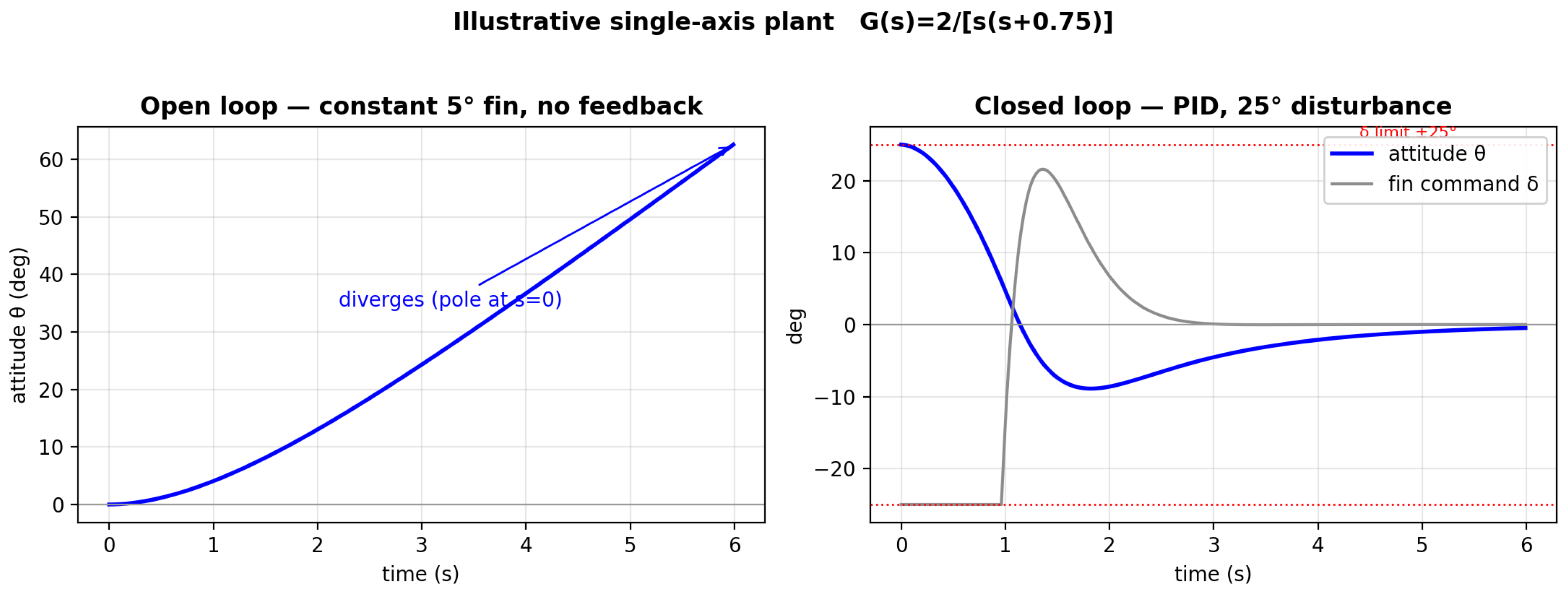
Figure 9.
Simulated open-loop yaw-rate spin-up. The yaw rate r accelerates from rest and plateaus at the hover equilibrium of (22), where the fan reaction torque is balanced by aerodynamic drag.
Figure 9.
Simulated open-loop yaw-rate spin-up. The yaw rate r accelerates from rest and plateaus at the hover equilibrium of (22), where the fan reaction torque is balanced by aerodynamic drag.
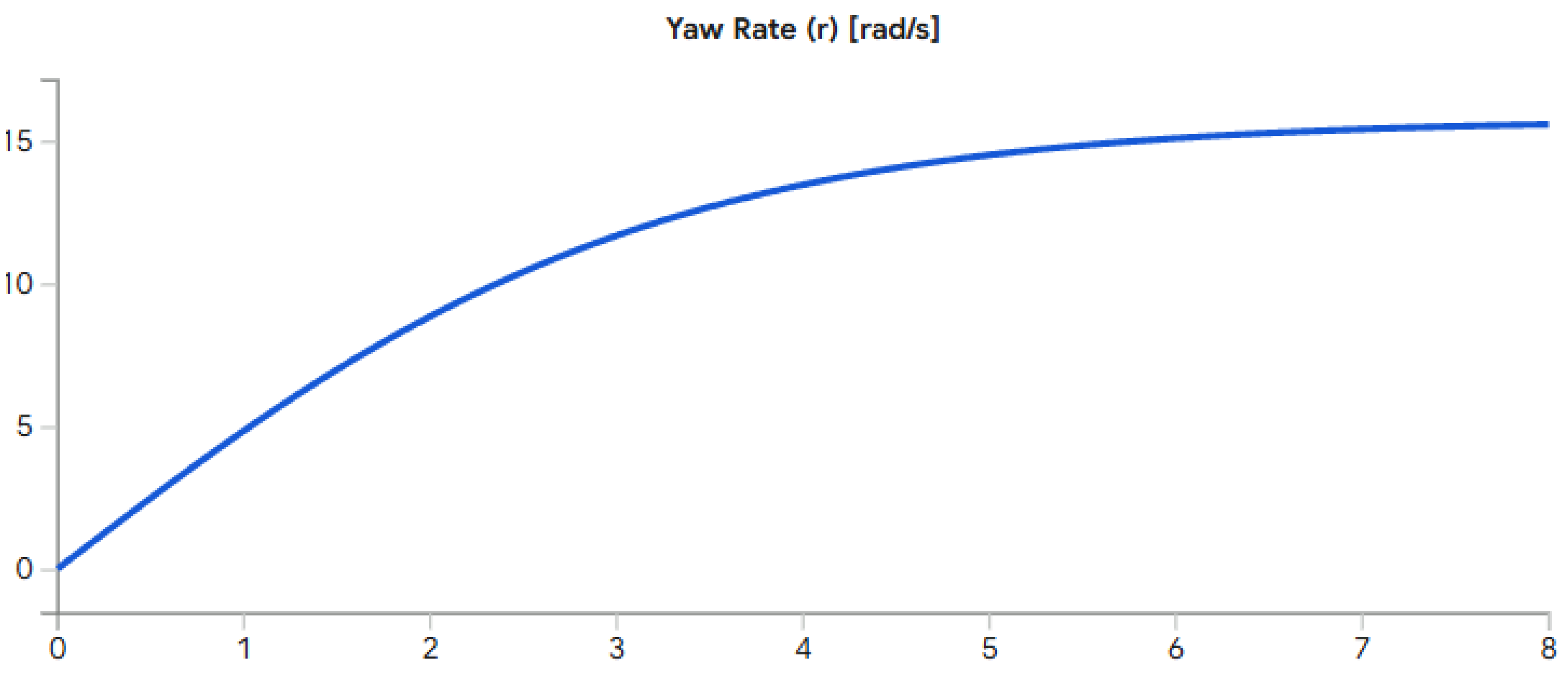
Figure 10.
Simulated unstable transverse response. When the oblate-inertia condition is not satisfied with adequate margin, the body rates diverge: the nutation envelope grows without bound, the failure mode guarded against by the major-axis rule [23].
Figure 10.
Simulated unstable transverse response. When the oblate-inertia condition is not satisfied with adequate margin, the body rates diverge: the nutation envelope grows without bound, the failure mode guarded against by the major-axis rule [23].
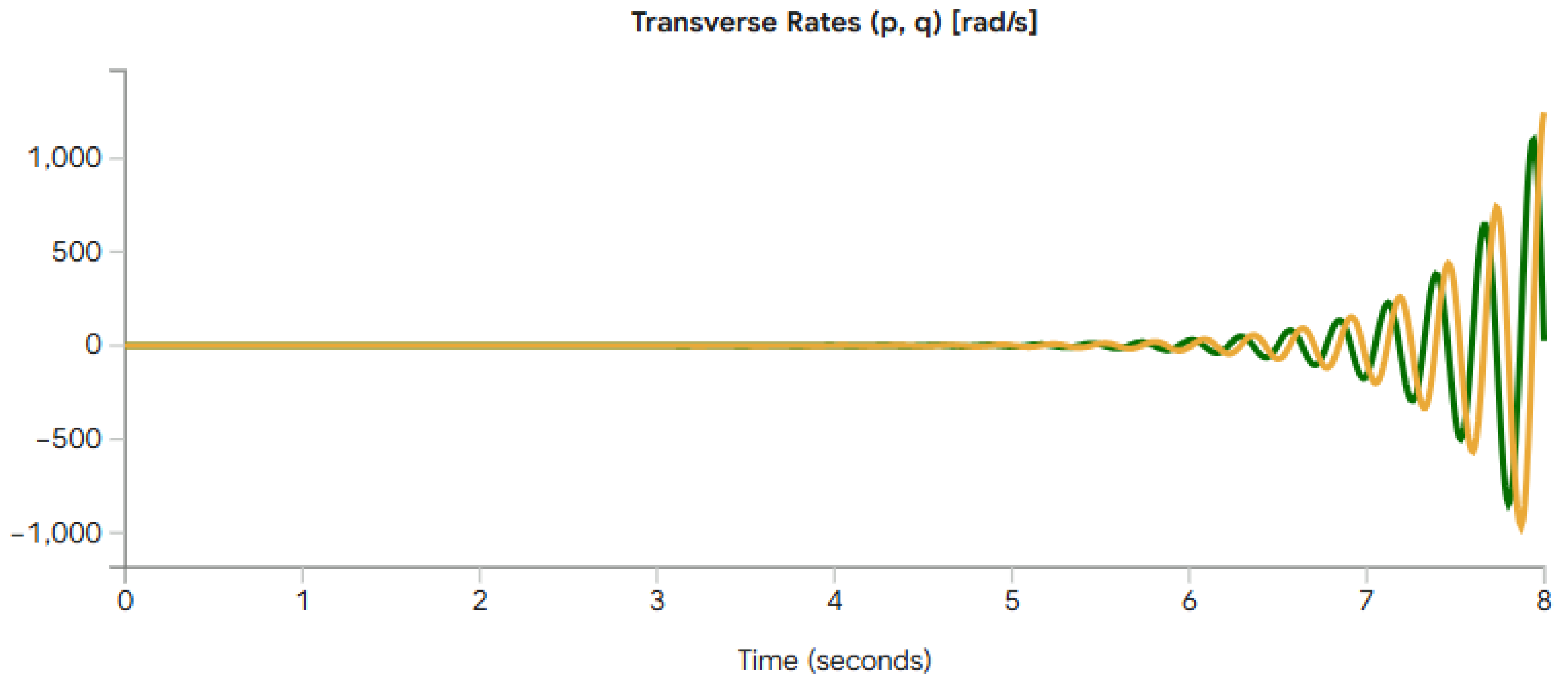
Figure 11.
Simulated stable transverse response. Following a gust at , the body rates exhibit the gyroscopic cross-coupling of (23) and are damped to zero by the fins, since the oblate condition is satisfied.
Figure 11.
Simulated stable transverse response. Following a gust at , the body rates exhibit the gyroscopic cross-coupling of (23) and are damped to zero by the fins, since the oblate condition is satisfied.
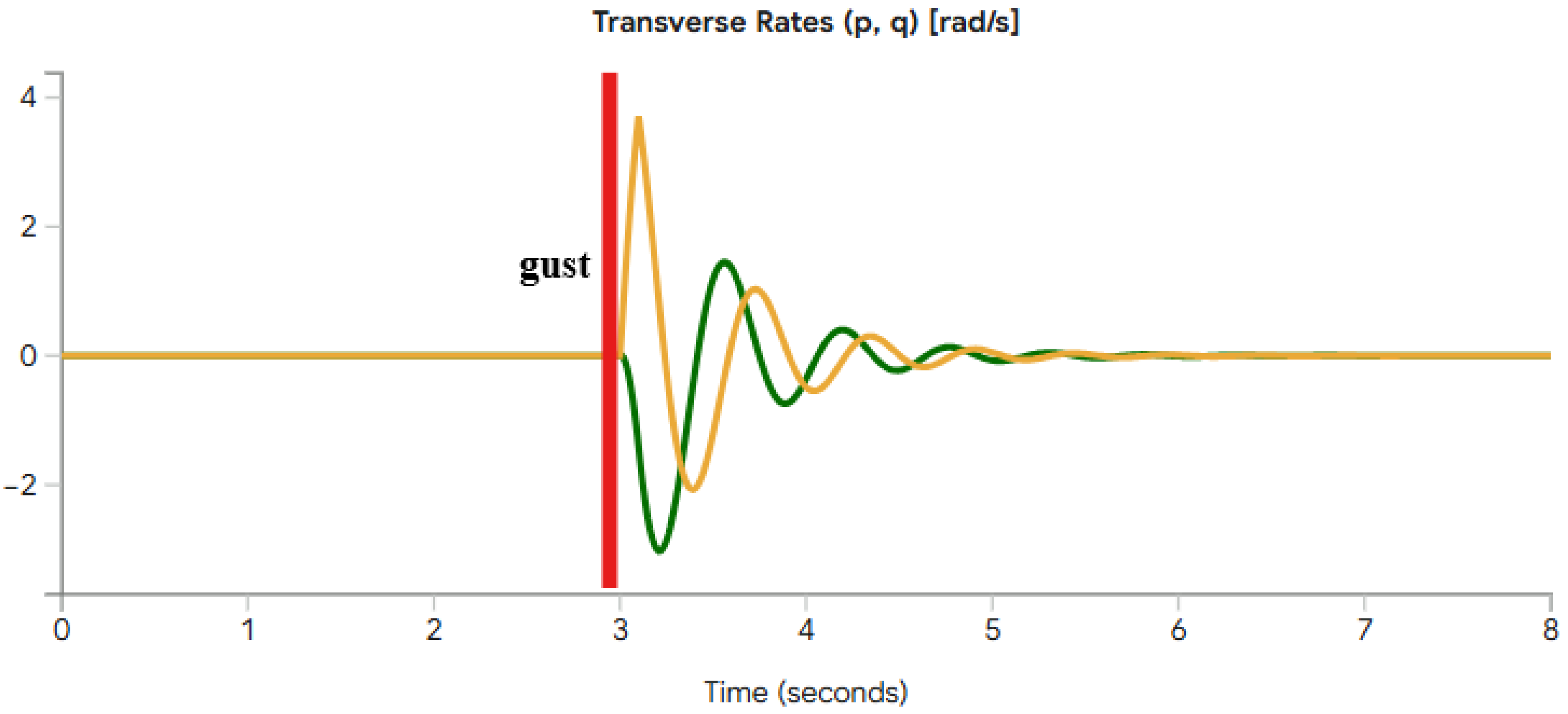

Table 1.
Proportional, integral, and derivative gains of the attitude controller used for the indoor flight tests. The self-leveling outer loop uses a proportional gain of 25.
Table 1.
Proportional, integral, and derivative gains of the attitude controller used for the indoor flight tests. The self-leveling outer loop uses a proportional gain of 25.
| Axis | |||
|---|---|---|---|
| Roll | 120 | 65 | 45 |
| Pitch | 120 | 65 | 45 |
| Yaw | 80 | 50 | 30 |
Table 2.
Servo-mixer allocation of the stabilized roll, pitch, and yaw demands to the four fins. Differential deflection of the and pairs produces the roll and pitch moments; a common-mode deflection of all four produces the yaw moment.
Table 2.
Servo-mixer allocation of the stabilized roll, pitch, and yaw demands to the four fins. Differential deflection of the and pairs produces the roll and pitch moments; a common-mode deflection of all four produces the yaw moment.
| Fin servo | Roll | Pitch | Yaw |
|---|---|---|---|
| 1 | − | 0 | − |
| 2 | 0 | − | − |
| 3 | 0 | + | − |
| 4 | + | 0 | − |
Table 3.
Representative parameters of the illustrative single-axis plant of (28).
Table 3.
Representative parameters of the illustrative single-axis plant of (28).
| Symbol | Value | Description |
|---|---|---|
| I | transverse inertia (stand-in for ) | |
| b | aerodynamic damping | |
| fin control effectiveness | ||
| fin deflection limit |
Disclaimer/Publisher’s Note: The statements, opinions and data contained in all publications are solely those of the individual author(s) and contributor(s) and not of MDPI and/or the editor(s). MDPI and/or the editor(s) disclaim responsibility for any injury to people or property resulting from any ideas, methods, instructions or products referred to in the content. |
© 2026 by the authors. Licensee MDPI, Basel, Switzerland. This article is an open access article distributed under the terms and conditions of the Creative Commons Attribution (CC BY) license (http://creativecommons.org/licenses/by/4.0/).
Copyright: This open access article is published under a Creative Commons CC BY 4.0 license, which permit the free download, distribution, and reuse, provided that the author and preprint are cited in any reuse.


