

Submitted:
04 July 2026
Posted:
06 July 2026
You are already at the latest version
Abstract
In order to address the climate crisis and reduce fossil fuel dependency, the REPowerEU plan and the "Fit for 55" package mandate a rapid green transition, including the transition to Electric and Fuel Cell Hybrid Electric Vehicles (EV-FCHEV) by 2035.
This study evaluates a poly-generative (PG) system integrating a biomass-fed ICE co-generator, a PhotoVoltaic (PV) system, and a PEM electrolyzer. Located in Rende, Italy (Lat. 39.3°N), the system is designed to reduce grid dependence by supplying electric energy for EV charging, hydrogen for FCHEV refueling, and thermal energy for building loads. The present work extends the energy as-sessment to four representative seasonal days, two mobility-demand scenarios, part-load ICE op-eration, and a Vehicle-to-Grid strategy to manage PV surplus and support fixed-load hydrogen production. This integrated approach aims to demonstrate the feasibility of decentralized energy systems combining renewable sources and biofuels. Under maximum-range conditions, the system reaches peak electrical and thermal outputs of 50 kW and 97 kW, respectively, while producing up to 9.23 kg of hydrogen per day for FCHEV refueling, the system successfully meets 100% of the building's domestic hot water requirements year-round.
Keywords:
poly-generative system
; internal combustion engine
; PEM electrolyzer
; PV plant
; electric vehicles
; fuel cell hybrid electric vehicles
1. Introduction
Aligned with the 'Fit for 55' climate package [1], the manufacturing of traditional gasoline and diesel internal combustion engine (ICE) vehicles is set to be phased out by 2035. These will be replaced by battery electric vehicles (EVs) and fuel cell hybrid electric vehicles (FCHEVs) to mitigate pollutant and greenhouse gas emissions. This shift toward green mobility necessitates a significant increase in electrical power capacity and hydrogen production. Consequently, the European Commission’s REPowerEU plan [2] seeks to eliminate fossil fuel dependency by accelerating renewable energy deployment and establishing a robust EU hydrogen market.
In this context, the implementation of innovative poly-generation and multi-source systems [3,4] offers a robust technical solution. The increasing adoption of well-established Photovoltaic (PV) technologies significantly enhances electrical power output [5,6] while simultaneously increasing the overall renewable energy share. Excess electricity generated from renewable sources can be utilized to produce green hydrogen via water electrolysis, a critical fuel for the next generation of fuel cell hybrid electric vehicles [7,8]. Currently, alkaline (A) and proton exchange membrane (PEM) electrolyzers represent the most prevalent commercial technologies for hydrogen production [9]. Furthermore, the Combined Heat and Power (CHP) paradigm provides a more efficient alternative to traditional systems by co-generating electrical and thermal energy.
Within the scope of CHP prime movers, Internal Combustion Engines (ICEs) represent a mature, dependable, and versatile technology [10]. These systems are notably compatible with biofuels [11], including syngas [12] derived from woody biomass gasification. By integrating a syngas-fueled ICE-CHP system with a PEM electrolyzer powered by photovoltaic (PV) energy, a comprehensive ICE-based poly-generative system is established.
A review of current literature indicates a scarcity of studies focusing on poly-generative systems that include hydrogen production [13,14,15,16,17,18,19,20]; furthermore, existing research [13,14,15,16] primarily addresses stationary energy applications rather than the emerging requirements of electric and fuel cell hybrid mobility.
A preliminary technical feasibility study of a fuel cell-based poly-generative energy system was introduced in [17]. Fed by either dry biogas or biomethane, this system was evaluated for the co-production of hydrogen, electric and thermal energies. It was specifically designed to satisfy the requirements of pure or hybrid fuel cell electric vehicles, alongside the electric and thermal loads of a residential building in Rende, Italy, focusing on representative winter and summer operating days. Subsequently, a parallel feasibility assessment was presented in [18] utilizing an internal combustion engine (ICE). This configuration operated on syngas derived from woody biomass gasification to generate identical energy outputs. While similarly optimized for electric mobility, its application was tailored to meet the energy demands of a countryside building within the same location and seasonal parameters.
A solar photovoltaic (PV) plant integrated with hydrogen production and storage was introduced in [19] to support a university transit fleet of 43 buses. The authors utilized TRNSYS® software for system modeling and simulation, while optimization was achieved via TrnOpt and GenOpt to account for the dynamic meteorological conditions of Gujrat (Pakistan), Fargo (USA), and London (UK).
Expanding on integrated configurations, the energetic and economic performance of a biomass-driven Combined Cooling, Heating, and Power (CCHP) system [20] were investigated. This setup simultaneously supplies an electric vehicle (EV) charging station and an alkaline electrolyzer for localized hydrogen generation. The evaluation considers two distinct biomass feedstock cost scenarios—specifically accounting for the presence or absence of market fuel costs—and benchmarks the system against the traditional practice of grid-exporting surplus electric energy. The findings establish the optimal sizing for the hydrogen infrastructure, demonstrating that prioritizing the self-consumption of renewable energy over grid export significantly enhances local energy efficiency and fosters sustainable mobility solutions.
This article expands upon the energy analysis of the syngas-fueled ICE-based poly-generative system originally introduced in [18]. The novelty of this study lies in the integrated assessment of a syngas-fuelled ICE/electrolyser poly-generative system under seasonal and mobility-dependent operating conditions. Compared with the previous preliminary ICE-based configuration, the present work extends the analysis to four representative seasonal days, considers two vehicle range scenarios, includes a larger hydrogen demand, and evaluates the part-load operation of the ICE. In addition, electric vehicle batteries are used within a Vehicle-to-Grid strategy to manage PV surplus, support hydrogen production, reduce grid dependence, and improve renewable energy self-consumption. The analysis also includes the use of recovered thermal energy for domestic hot water, space heating, and summer cooling through an absorption chiller.
A comprehensive technical analysis is conducted to evaluate the system's electrical and thermal power outputs, efficiencies, and hydrogen production. This assessment considers a specific fleet of pure electric and hybrid fuel cell (FC) electric vehicles, explicitly accounting for variations in their daily travel distances. Furthermore, the study determines the system's coverage percentages for both the electrical and thermal loads of the building. These parameters are rigorously quantified across the four representative seasonal days to assess overall reliability.
2. Electric and Thermal Profiles of the Countryside Building and the Green Vehicle Fleet
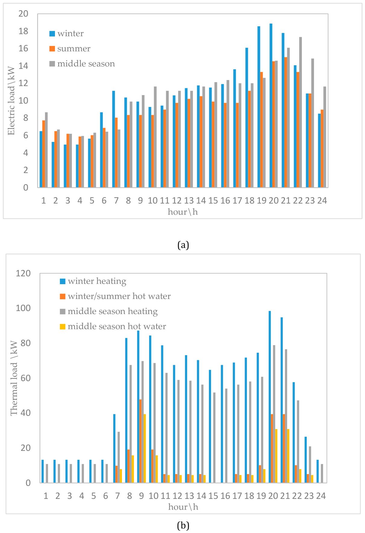
Following the methodology established in [17,18,21,22], this section defines the temporal profiles of the building's thermal and electrical demands. These profiles are statistically derived from occupant behavior, local climatic data, and the specific volumes served by the poly-generative system, with the inclusion of data for a typical mid-season day (spring or autumn). Electrical demand encompasses all household appliances, whereas thermal demand includes space heating, domestic hot water production, and the heat to supply the generators of absorption chillers to use for space cooling . The facility comprises five floors, with individual apartment net areas of 100, 150, and 200 m², alongside a 1000 m² flat open space suitable for photovoltaic (PV) system installation. The hourly profiles for the electrical and thermal loads are calculated using Equation (1) from [17]. Furthermore, a common service fraction fcs of 0.10 is applied to account for the electrical consumption of common services, such as stairway and garage lighting. The resulting electrical and thermal load profiles for the building are illustrated in Figure 1.
Based on the statistics reported in [22], each family inhabiting the building is assumed to consist of four members and own two vehicles. The vehicle fleet comprises three distinct models (A: Fiat 500E; B: Tesla Model Y Long Range; C: Toyota Mirai MY23 Pure), whose technical specifications are sourced from [24,25,26]. Models A and B are battery electric vehicles (BEVs) suitable for short- and medium-distance travel, respectively, whereas Model C is a fuel cell hybrid electric vehicle (FCHEV) utilized for long-range trips. The total count, alongside the minimum and maximum average daily travel distances for each vehicle type, is summarized in Table 1. To account for the longer commuting distances typical of rural residents compared to urban residents, the maximum distance for Model A was increased by 10% relative to the baseline data in [27]. Considering the fleet size, technical constraints, and travel ranges of the pure electric vehicles, seven 7.5 kW charging stations are proposed. The first charging point serves the 15 units of Model A, while the remaining six stations charge the 12 units of Model B. Assuming a 12-hour overnight charging window (from 8:00 PM to 8:00 AM), the required charging duration is estimated at approximately 11.8 hours for maximum travel distances and 8.3 hours for minimum travel distances.
Figure 1.
Time trends of the electrical load (a) and of the thermal loads for hot water production and for heating for the countryside building (b).
Figure 1.
Time trends of the electrical load (a) and of the thermal loads for hot water production and for heating for the countryside building (b).
In order to support the vehicle recharging infrastructure, a maximum total electrical power of 52.5 kW is required throughout the entire charging duration. This electrical demand is satisfied, either partially or fully, by an internal combustion engine (ICE) system. The ICE is fueled by syngas, which is generated via the gasification of woody biomass.
3. ICE Based Poly-Generative System
The simplified layout of the poly-generative system is illustrated in Figure 2. The configuration comprises a photovoltaic (PV) plant that converts solar energy into electrical energy, and a hydrogen (H2) production system. The latter utilizes bi-distilled water and a portion of the PV plant generated electric energy to produce hydrogen, subsequently compressing it to high pressures (up to 750 bar) to satisfy the refueling requirements of the fuel cell hybrid electric vehicles (Type C). Additionally, a woody biomass-fueled internal combustion engine (ICE) system generates the electric energy necessary to recharge the battery electric vehicles (Types A and B). The thermal energy recovered from the ICE system meets the residential heating, cooling (via absorption chillers), and domestic hot water demands of the building. Any surplus electric energy generated by the PV plant covers the internal electrical loads of the building or it is directed to the vehicle-to-grid (V2G) system for EV charging. Within the V2G framework, selected electric vehicles act as storage media, absorbing excess PV plant energy generation during peak production hours and later discharging this energy to power the hydrogen production system during periods of low solar energy availability. Detailed descriptions of the primary poly-generative components are provided in the following subsections.
3.1. Photovoltaic Plant
The photovoltaic (PV) plant was selected and sized in accordance with the methodology described in [18]. The facility and the building are assumed to be located in a rural area near Rende, Cosenza, Italy (39°20′ N, 16°11′ E). An open, flat area measuring 25 m × 40 m is available adjacent to the building, providing an ideal space to host the PV panels tilted at the local latitude angle. The chosen PV modules utilize monocrystalline cells, each featuring dimensions of 1.038 m × 1.755 m, a rated peak power of 380 W, and an electrical efficiency of 20.9%. Further technical specifications are detailed in [28]. The complete PV array consists of 552 panels oriented toward South and tilted of place latitude angle, with comprehensive system details available in [18]. Naturally, the total photovoltaic energy yield depends on the local solar energy profile of the installation site.
Consequently, the electrical power profiles generated by the entire PV plant are presented for four typical seasonal days: winter solstice (21 December), vernal equinox (21 March), summer solstice (21 June), and autumnal equinox (22 September). The PV system was simulated within the TRNSYS 18 environment using meteorological data collected from a weather station at the University of Calabria, which were integrated via an external data reader. TRNSYS utilizes modular components, termed "Types," to model specific physical or virtual devices. The PV array was modeled using the "four-parameter" equivalent electrical circuit, where the core parameters depend on the module's electrical characteristics. These Types are interconnected sequentially, with the output of one component serving as the input for the next. Specifically, Type 16a was employed to decompose global horizontal radiation into direct and diffuse components, interpolate radiation data, calculate solar position, and estimate solar power on the tilted surfaces. The PV panels were modeled using Type 103b, assuming continuous operation at the maximum power point (MPP). This Type accurately evaluates the electrical performance of monocrystalline and polycrystalline modules. According to the manufacturer's specifications, the short-circuit current (Isc) and the temperature coefficients in open-circuit voltage (Voc) are 0.004596 A/K and -0.11 V/K, respectively. This component directly calculates the array power output at the maximum power point by accounting for thermal drift and cell temperature fluctuations under real operating conditions. The TRNSYS simulations were conducted with a 15-minute time step.
The representative days were selected to evaluate the system under characteristic conditions for each of the four seasons, specifically regarding the solar irradiance incident on the PV plane. Figure 3 illustrates the simulated Direct Current (DC) electrical power profiles generated by the PV plant. In December, power generation occurs from 6:30 AM to 3:00 PM, achieving a peak DC power output of approximately 130 kW. In March, the operational window extends from 6:00 AM to 6:00 PM, with an identical peak power of 130 kW. During the summer solstice in June, production starts at 4:15 AM and lasts until 6:00 PM, reaching an increased peak power of 150 kW. The highest peak of 171 kW is recorded in September, with production spanning from 6:00 AM to 6:00 PM. In terms of overall energy yield, the PV plant delivers a total daily DC electrical energy of 622 kWh in December, 674 kWh in March, 1037 kWh in June, and 1166 kWh in September.
3.2. Hydrogen Production System
The hydrogen production system consists of a Proton Exchange Membrane (PEM) electrolyzer and a compression section. The PEM electrolyzer generates low-pressure hydrogen (up to 15 bar) utilizing bi-distilled water and electric energy supplied by the PV plant, while the subsequent compression section elevates the hydrogen pressure up to 750 bar to meet the refueling requirements of the fuel cell hybrid electric vehicles (Type C).
A dedicated simulation tool based on the dynamic electrical model of a PEM electrolyzer was developed in the Simulink® environment; this tool was previously validated against experimental data from a commercial unit in [29] and subsequently utilized in [17].
The Proton Exchange Membrane (PEM) stack serves as the core of the electrolyzer system, which integrates a DC/DC buck converter, auxiliary measurement and control devices, and hydrogen storage units. Utilizing the developed simulation tool, the optimal operating current range for the PEM electrolyzer was determined. This configuration yields a hydrogen production efficiency of approximately 65% based on the High Heating Value (HHV) at an hydrogen flow rate of roughly 60% of its maximum rated hydrogen production capacity, establishing a suitable baseline for system-level energy balance evaluations. The simplified model employed in this study directly aligns with the comprehensive, dynamic electrical model validated in [29], which characterizes variations in hydrogen mass flow and efficiency relative to absorbed power. To meet the maximum daily mileage requirements of Type C vehicles under worst-case winter conditions (characterized by minimum solar irradiance), the PEM electrolyzer system from [29] was scaled up. Integration with electric vehicle (EV) batteries supports this operation. By functioning within the previously identified optimal current range, the electrolyzer maintains a stable production rate and a consistent 65% HHV efficiency. Furthermore, the EV batteries stabilize the system by delivering a constant power input, enabling fixed-load operation during periods of low solar irradiation. This approach ensures that the experimentally validated PEM model remains reliable when scaled for system-level analysis. Finally, based on the input parameters defined in Table 2, the calculation tool executes the dynamic electrical model to determine both the mass flow rate and the resulting production efficiency of the generated hydrogen.
Based on the vehicles' technical specifications [24,25,26] and the daily mileage data [27], the Type C fleet requires a total hydrogen mass of approximately 9.23 kg under maximum range conditions and 6.46 kg under minimum range conditions. The sizing of the PEM electrolyzer was performed starting from the daily hydrogen demand of the type C vehicles. Once the hydrogen mass required under the maximum- and minimum-range conditions was defined, the electrolyzer was scaled from the validated PEME model reported in [29]. The system was assumed to operate at a constant electrical input within the previously identified high-efficiency operating range, corresponding to an H₂ production efficiency of about 65% on an HHV basis. Therefore, the operating time of the electrolyzer was determined by matching the required daily hydrogen production with the selected constant input power. To generate this required hydrogen mass, the PEM electrolyzer operates at a constant electrical power input of about 71 kW for 8.5 hours in the maximum range scenario and 5.95 hours in the minimum range scenario. Subsequent hydrogen compression up to 750 bar demands an additional 43.2 kWh of electrical energy across all seasonal typical days. In this way, the hydrogen production system is operated at fixed load, while the EV batteries are used to compensate for the mismatch between the instantaneous PV generation and the electrolyzer power demand. This allows the PEM electrolyzer to remain within its optimal operating range even when solar irradiance is not sufficient to directly supply the required power. Notably, the total energy, which is required for both hydrogen production and compression, is supplied entirely by the PV plant throughout all investigated scenarios.
3.3. ICE Based Co-Generator Fed by Syngas from Woody Biomass
Given that the total peak power required for vehicle charging is 52.5 kW, an internal combustion engine (ICE) fueled by syngas from woody biomass gasification is selected, featuring a nominal electrical capacity of 50 kWel. The national electricity grid supplies the remaining power when necessary. The thermal management system recovers waste heat from both the engine lubricant oil and exhaust gases to satisfy space heating and domestic hot water demands. According to [30], the engine operates at an electrical efficiency of approximately 33% and a thermal efficiency of 64%.
Under maximum range conditions, the operational scheduling varies seasonally as follows:
- Winter and Spring: the ICE operates at nominal full capacity for approximately 12 hours.
- Summer: the system runs at 30 kW for 36 minutes and at 37.5 kW for 11.2 hours; the remaining charging load is covered by routing surplus PV electricity to directly charge approximately five Type B vehicles via the V2G framework.
- Autumn: the engine operates at 22.5 kW for 1.7 hours and at 30 kW for 10.1 hours, while excess energy from the PV plant is leveraged to charge around seven Type B vehicles through the V2G network.
Under minimum range conditions, the seasonal scheduling of the system is managed as follows:
- Winter and Spring: The ICE operates at an electrical output of 42.5 kW for 7.4 hours and at full nominal power (50 kW) for 0.9 hours. The electrical power not allocated to hydrogen production is redirected to charge approximately 15 Type A vehicles through the V2G framework.
- Summer: The system runs at 22.5 kW for 6.8 hours and at 30 kW for 1.5 hours. During this period, surplus electricity from the PV plant charges about six Type B vehicles, while the excess power not consumed by the hydrogen production unit recharges approximately 15 Type A vehicles via the V2G system.
- Autumn: The engine operates at 15 kW for 7.4 hours and 22.5 kW for 0.9 hours. The combined surplus from both the PV generation and the unutilized hydrogen production power is dispatched via V2G to charge 9 Type B vehicles and 15 Type A vehicles, respectively.
The Internal Combustion Engine can operate under part-load conditions in order to increase the flexibility of the poly-generative system. The variation in engine performance with load was evaluated using efficiency data available for a similar syngas-fuelled ICE [30]. As shown in Figure 4, the electrical efficiency decreases when the engine load is reduced, whereas the thermal efficiency increases. For example, at 30% of the rated electric power, the electrical efficiency decreases to 20.7%, while the thermal efficiency increases to 74.2%. This behavior was taken into account in the energy analysis when defining the seasonal operating schedules of the ICE.
3.4. HVAC System
Thermal energy recovered from the ICE is used to heat the building by supplying fan-coils as emission system with an inlet temperature of 50 °C. The supply is indirect by interposing a thermal storage system between the ICE and the heating plant maintained at a set point temperature of 85 °C. Inside the accumulator, a further heat exchanger is foreseen for the production of domestic hot water. In summer, thermal energy drives single-effect absorption chillers to produce chilled water rates for cooling applications that supply the same emission system. Inlet temperature is variable as a function of the climatic conditions, in particular of the wet bulb temperature, ranging from 10°C to 16 °C. The simulated chiller has a rated COP of 0.6, with the generator supplied by hot water at 80 °C whereas the heat into the condenser is exhausted by an evaporative tower.
3.5. Variable Renewable Energy Storage System
In the proposed configuration, the EV batteries are not considered only as final electricity users, but also as flexible storage units within a Vehicle-to-Grid energy management strategy. The operating logic is based on a priority order. First, the PV electricity is used to supply the hydrogen production system, in order to meet the daily hydrogen demand of the Type C vehicles. When the instantaneous PV generation is lower than the electrolyzer power demand, the EV batteries discharge the previously stored surplus electricity to keep the PEM electrolyzer operating at fixed load. Second, once the hydrogen production requirement is satisfied, the remaining PV electricity is used to cover the building electrical load. Finally, any residual surplus is stored in the EV batteries or directly used to recharge the Type A and Type B vehicles, depending on the seasonal energy availability and the selected range scenario.
According to this operating logic, the poly-generative system requires two main variable electrical storage functions. The first one is needed to compensate for the mismatch between PV generation and the power required by the hydrogen production system. The second one is used to store residual surplus PV electricity after the hydrogen production and building electrical loads have been satisfied. Both functions can be effectively provided by the Li-ion batteries of the Type A and Type B electric vehicles.
While an EV battery must primarily retain the energy required for the vehicle to complete its designated trip, this demand does not exhaust its total storage capacity. The remaining battery capacity offers an operational margin for energy storage and release. Consequently, the vehicle batteries can simultaneously manage the energy required for transportation and serve as a dynamic buffer to store or discharge surplus electrical energy until full charge capacity is reached.
Under maximum range conditions, the fleet requirements for energy management across the typical seasonal days are defined as follows:
- Winter: either 5 Type A vehicles or 8 Type B vehicles are required to secure the electrical power demand of the hydrogen production system.
- Spring: 2 Type A vehicles and 5 Type B vehicles are necessary to regulate the electrical energy exchanges between the PV system and the building.
- Summer: 2 Type A vehicles and 4 Type B vehicles are allocated to manage the electricity exchanges between the PV plant and the building, while an additional 5 Type B vehicles are required to store the surplus PV electric generation and complete their own recharging cycle.
- Autumn: 4 Type A vehicles and 6 Type B vehicles are deployed to balance the energy flows between the PV system and the building, whereas 7 Type B vehicles are needed to absorb the excess PV electric generation and perform self-recharging.
Under minimum range conditions, the fleet allocation required to support the energy management functions changes according to the season as follow:
- Winter: either 4 Type A vehicles or 5 Type B vehicles are required to guarantee the electrical power demanded by the hydrogen production system.
- Spring: 2 Type A vehicles and 3 Type B vehicles are necessary to regulate the electrical energy exchanges between the PV system and the building.
- Summer: 2 Type A vehicles and 2 Type B vehicles are allocated to manage the power interactions between the PV plant and the building, while 6 Type B vehicles are needed to absorb the surplus PV electric generation and complete their own recharging process.
- Autumn: 2 Type A vehicles and 5 Type B vehicles are utilized to balance the energy flows between the PV plant and the building, whereas 9 Type B vehicles are required to store the residual excess PV electric energy and undergo replenishment.
4. Results and Discussion on the Energy Analysis of the Poly-Generative System
The poly-generative system leverages renewable energy sources—specifically solar irradiance and a biogenic fuel (syngas)—to generate the electric energy required to charge Type A and B electric vehicles, as well as the compressed hydrogen needed to refuel Type C vehicles across all typical days. Figure 5 illustrates the comprehensive energy flows and fuel mass balances for the poly-generative system under both maximum and minimum range conditions. In the maximum and minimum range scenarios, the electrical and thermal efficiencies of the syngas-fueled ICE system vary from 26.4% to 33.5% and from 70.7% to 63.9%, and from 24.5% to 33.5% and 72.6% to 63.9%, respectively. The national electric grid provides only a minor auxiliary input (2.5 kW) exclusively during typical winter and spring days. Consequently, the newly introduced green vehicle fleet is almost entirely sustained by the poly-generative system. This result highlights the role of the syngas-fuelled ICE as a dispatchable renewable-based generator, able to compensate for the lower PV contribution during the least favorable seasonal conditions. The limited grid integration required in winter and spring confirms that the combined use of biomass-derived syngas, PV electricity and EV-based storage can strongly reduce the dependence of the mobility system on the national electric grid.
The daily woody biomass consumption was calculated from the electrical load covered by the syngas-fueled ICE, based on the engine efficiencies and on the biomass-to-syngas conversion assumptions reported in [30] and in a previous work [31].
Under maximum range conditions, the total daily consumption of woody biomass amounts to approximately 497 kg in winter and spring, 409 kg in summer, and 343 kg in autumn, yielding a constant daily compressed hydrogen mass of 9.23 kg.
Under minimum range conditions, the total daily consumption of woody biomass amounts to approximately 317 kg during winter and spring days, 207 kg on summer day, and 149 kg on autumn day, yielding a daily compressed hydrogen mass of about 6.46 kg. The reduction in woody biomass consumption from winter/spring to summer and autumn is mainly due to the higher PV electricity availability, which allows part of the electric vehicle charging demand to be covered directly by solar energy. This effect is more evident under minimum-range conditions, where the lower mobility demand further increases the possibility of using PV surplus and reduces the required operating load of the ICE. The electricity generated by the PV plant entirely covers the energy consumption required for hydrogen production and compression across all typical days and range scenarios. In summer and autumn days, the surplus electric energy from the PV plant is utilized to recharge the electric vehicles, thereby minimizing woody biomass consumption while completely satisfying the building's internal electrical load on those days. Therefore, the V2G strategy does not only provide temporary storage for the hydrogen production system, but also increases the local self-consumption of PV electricity. This is particularly relevant in summer and autumn, when the mismatch between PV generation and instantaneous demand would otherwise lead to unused renewable electricity or additional grid exchanges. Furthermore, under both maximum and minimum range conditions, the thermal energy recovered from the system fully covers the building's domestic hot water demand throughout the year. Conversely, space heating demands during winter, spring, and autumn days are partially met by the system's thermal output, achieving coverage factors of 71.3%, 91.3%, and 61.5% under maximum range conditions, and 39.5%, 52.4%, and 26.1% under minimum range conditions, respectively. Finally, thermal energy surpluses of 726 kWh and 310 kWh are recorded on summer days for the maximum and minimum range scenarios, respectively. These results show that the thermal recovery section is highly effective for domestic hot water production, which is fully covered in all investigated cases. However, the space-heating coverage remains partial because the thermal demand profile of the building is not always aligned with the operating schedule and thermal output of the ICE. In summer, the recorded thermal surplus indicates that further optimisation of the cooling section or thermal storage capacity could improve the exploitation of the recovered heat.
Figure 5.
Diagram of the energy flows and of the fuels masses for the poly-generative system in maximum and minimum range conditions.
Figure 5.
Diagram of the energy flows and of the fuels masses for the poly-generative system in maximum and minimum range conditions.
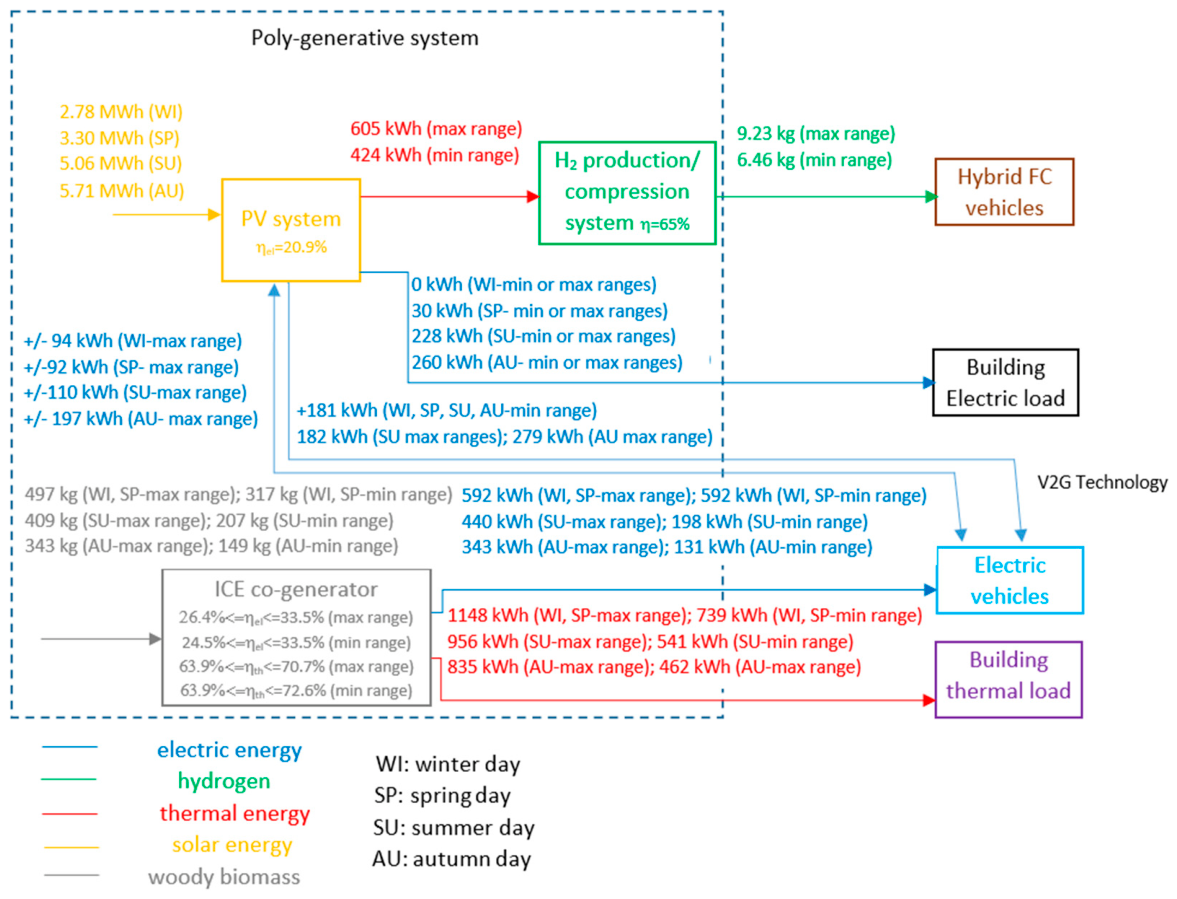
Figure 6 displays the temporal profiles of the electrical and thermal power outputs, alongside the hydrogen mass generated by the poly-generative system across all typical seasonal days under both maximum and minimum range conditions. The highest electrical power demands imposed on the poly-generative system occur during the typical winter day, a period characterized by the lowest solar energy contribution.
On the other typical days, the net electrical power drawn from the poly-generative system plant is significantly lower due to enhanced solar availability; the observed power increases during these periods are exclusively associated with completing the charging cycles of the Type A and B battery electric vehicles. Compared to the maximum range scenario, the minimum range condition exhibits narrower power delivery intervals and lower electrical requirements. This reduction is driven by the lower energy consumption of the Type A and B fleets and the decreased hydrogen demand of the Type C fuel cell vehicles, which collectively yield substantial electric energy savings for hydrogen production and compression. Ultimately, these findings confirm the system’s capability to operate efficiently across seasonal variations and fluctuating mobility demands.
Overall, the results demonstrate that the proposed configuration can adapt to different seasonal and mobility-demand conditions by combining the dispatchability of the syngas-fueled ICE with the renewable contribution of the PV plant and the flexibility provided by EV batteries. The main benefit of this integrated approach is the simultaneous reduction of grid dependence, woody biomass consumption and unused PV electricity, while maintaining hydrogen production for long-range FCHEV operation.
5. Conclusions
This study presents a comprehensive energy assessment of a renewable internal combustion engine (ICE) and electrolyzer-based poly-generative system designed to support an alternative green mobility infrastructure. The system performance was evaluated across four characteristic seasonal days and under two distinct vehicle driving range scenarios.
The poly-generative system, fed by renewable energy sources including solar energy and syngas produced through woody biomass gasification, can operate under part-load conditions and produces electricity for charging Type A and Type B electric vehicles, as well as compressed hydrogen for refueling Type C vehicles, across all the investigated seasonal days. Only a minor electrical power integration of 2.5 kW from the national grid is required during the typical winter and spring days, confirming that the green vehicle fleet is almost entirely supplied by the poly-generative system.
Depending on the driving range constraints (maximum and minimum), the electrical and thermal efficiencies of the syngas-fired ICE vary within the intervals of 26.4%–33.5% and 70.7%–63.9% for the maximum range, and 24.5%–33.5% and 72.6%–63.9% for the minimum range, respectively.
Under maximum range conditions, the total daily consumption of woody biomass amounts to approximately 497 kg for winter/spring days, 409 kg for summer days, and 343 kg for autumn days, corresponding to a daily compressed hydrogen output of 9.23 kg. In comparison, under minimum range conditions, the daily biomass consumption decreases to 317 kg (winter/spring), 207 kg (summer), and 149 kg (autumn), yielding a daily hydrogen mass of 6.46 kg. The electricity generated by the PV plant completely covers the power demand for hydrogen production and compression across all investigated typical days and driving ranges. During summer and autumn days, surplus solar electric energy is effectively utilized to recharge the electric vehicles—thereby minimizing biomass feedstock consumption—while fully satisfying the building’s internal electrical load. Furthermore, the thermal energy recovered from the system achieves a 100% coverage fraction for the building's domestic hot water demand in all seasonal scenarios and under both driving range conditions.
Regarding building air conditioning, the system's thermal output partially satisfies the building's heating loads during winter, spring, and autumn days. Specifically, the heating coverage factors reach 71.3%, 91.3%, and 61.5% under maximum range conditions, and 39.5%, 52.4%, and 26.1% under minimum range conditions, respectively. Conversely, unutilized thermal energy surpluses of 726 kWh and 310 kWh are recorded on typical summer days for the maximum and minimum range scenarios, respectively.
Overall, the proposed poly-generative architecture demonstrates the potential of coupling a dispatchable syngas-fueled ICE with a PV plant, a PEM electrolyzer and EV-based storage to support both green mobility and building energy demands. The use of Vehicle-to-Grid operation improves the exploitation of PV surplus, supports fixed-load hydrogen production and reduces the dependence on the national grid. At the same time, the recovered heat from the ICE is effectively used to satisfy domestic hot water demand and partially cover space-heating requirements.
This approach, based on four representative seasonal days and system-level simulations, provides a useful assessment of the system behavior under characteristic operating conditions.
Author Contributions
Conceptualization, G.D.L.; methodology, G.D.L. and N.B.; software, G.D.L. R.B. P.B.; validation, G.D.L.; formal analysis, G.D.L. P.B. P.M.; investigation, G.D.L.; re-sources, N.B.; data curation, G.D.L.; writing—original draft preparation, G.D.L. and N.B.; writing—review and editing, G.D.L. R.B., P.B., P.M., and N.B.; visualization, G.D.L.; supervision, N.B.; project administration, N.B.; funding acquisition, N.B.
All authors have read and agreed to the published version of the manuscript.
Funding
This study was carried out in the Electrolife project that is supported by the Clean Hydrogen Partnership and its members and has received funding from the Horizon Europe programme under grant agreement No 101137802.
Institutional Review Board Statement
Not applicable.
Conflicts of Interest
The authors declare no conflict of interest. Views and opinions expressed are however those of the author(s) only and do not necessarily reflect those of the European Union or the Clean Hydrogen Partnership. Nei-ther the European Union nor the granting authority can be held responsible for them.
Nomenclature
| Symbols | ||
| N | number | - |
| P | Power | kW |
| R | Resistance | Ω |
| DR | Resistance variation | Ω |
| C | Capacitance | F |
| f | frequency | Hz |
| L | inductance | H |
| Subscripts | ||
| el | Electric | |
| th | thermal | |
| cs | common services | |
| hw | hot water | |
| heat | heating | |
| ss | referred to the short stack | |
| min | minimum value | |
| c | referred to the cell elements in a short stack | |
| id | ideal | |
| an | anode | |
| mem | membrane | |
| cat | cathode | |
| sw | switch | |
| in | input | |
| stab2 | output stabilizing | |
| 1 | output branch | |
| el | electric | |
| DC | Direct Current | |
| in1 | Input branch | |
| out1 | Output branch | |
References
- The European “fit for 55” plan. Available online: https://www.consilium.europa.eu/it/policies/green-deal/fit-for-55-the-eu-plan-for-a-green-transition/ (accessed on 25 June 2026).
- The European REPowerEU plan. Available online: https://www.consilium.europa.eu/it/policies/eu-recovery-plan/repowereu/ (accessed on 25 June 2026).
- Rong, A.; Lahdelma, R. Role of polygeneration in sustainable energy system development challenges and opportunities from optimization viewpoints. Renew. Sustain. Energy Rev. 2016, 53, 363–372. [Google Scholar] [CrossRef]
- Settino, J.; Ferraro, V.; Morrone, P. Energy analysis of novel hybrid solar and natural gas combined cycle plants. Appl. Therm. Eng. 2023, 230, 120673. [Google Scholar] [CrossRef]
- Settino, J.; Sant, T.; Micallef, C.; Farrugia, M.; Spiteri Staines, C.; Licari, J.; Micallef, A. Overview of solar technologies for electricity, heating and cooling production. Renew. Sustain. Energy Rev. 2018, 90, 892. [Google Scholar] [CrossRef]
- Bevilacqua, P.; Perrella, S.; Bruno, R.; Arcuri, N. An accurate thermal model for the PV electric generation prediction: Long-term validation in different climatic conditions. Renew. Energy 2021, 163, 1092. [Google Scholar] [CrossRef]
- De Lorenzo, G.; Andaloro, l.; Sergi, F.; Napoli, G.; Ferraro, M.; Antonucci, V. Numerical simulation model for the preliminary design of hybrid electric city bus power train with polymer electrolyte fuel cell. Int. J. Hydrog. Energy 2014, 39(24), 12934. [Google Scholar] [CrossRef]
- De Lorenzo, G.; Piraino, F.; Longo, F.; Tinè, G.; Boscaino, V.; Panzavecchia, N.; Caccia, M.; Fragiacomo, P. Modelling and Performance Analysis of an Autonomous Marine Vehicle Powered by a Fuel Cell Hybrid Powertrain. Energies 2022, 15(19), 6926. [Google Scholar] [CrossRef]
- Wappler, M.; Unguder, D.; Lu, X.; Ohlmeyer, H.; Teschke, H.; Lueke, W. Building the green hydrogen market – Current state and outlook on green hydrogen demand and electrolyzer manufacturing. Int. J. Hydrog. Energy 2022, 47(79), 33551. [Google Scholar] [CrossRef]
- Castiglione, T.; Falbo, L.; Perrone, D.; Bova, S. Cooling on-demand for knock prevention in spark-ignition engines: An experimental analysis. Appl. Therm. Eng. 2021, 195(12), 117161. [Google Scholar]
- Falbo, L.; Perrone, D.; Morrone, P.; Algieri, A. Integration of biodiesel internal combustion engines andtranscritical organic Rankine cycles for waste-heat recoveryin small-scale applications. Int. J. Energy Res. 2022, 46(4), 5235–5249. [Google Scholar]
- Perrone, D.; Castiglione, T.; Morrone, P.; Pantano, F.; Bova, S. Numerical and experimental assessment of a micro-combined cooling, heating, and power (CCHP) system based on biomass gasification. Appl. Therm. Eng. 2023, 219, 119600. [Google Scholar]
- Khalid, F.; Kumar, R. Thermodynamic assessment of a new PTC operated polygeneration system for fresh water, cooling, electricity and hydrogen production for a residential community. Int. J. Hydrog. Energy 2023, 48, 38991–39001. [Google Scholar] [CrossRef]
- Luqman, M.; Al-Ansari, T. Energy, water and food security through a wastedriven polygeneration system for sustainable dairy production. Int. J. Hydrog. Energy 2022, 47(5), 3185. [Google Scholar] [CrossRef]
- Minutillo, M.; Perna, A.; Sorce, A. Combined hydrogen, heat and electricity generation via biogas reforming: Energy and economic assessments. Int. J. Hydrog. Energy 2019, 44(43), 23880. [Google Scholar] [CrossRef]
- Hai, T.; Ali, M.A.; Alizadeh, A.; Almojil, S. F.; Almohana, A. I.; Chauhan, B. S.; Alali, A. F.; Raise, A. Optimization next to environmental analysis of harvesting waste heat from a biomass-driven externally-fired gas turbine cycle for sub-zero cooling and production of hydrogen, freshwater, and hot water. Appl. Term. Eng. 2023, 223, 119884. [Google Scholar]
- De Lorenzo, G.; Corigliano, O.; Piraino, F.; Genovese, M.; Fragiacomo, P. Technical feasibility study of a renewable fuel cell/electrolyzer poly-generative system. E3S Web Conf. 2023, 414, 03014. [Google Scholar]
- De Lorenzo, G.; Bevilacqua, P.; Morrone, P.; Arcuri, N.; Fragiacomo, P. Technical analysis of a renewable woody biomass generator/electrolyzer poly-generative system. E3S Web Conf. 2023, 414, 03015. [Google Scholar]
- Saleem, M. S.; Abas, N. A solar assisted grid-tied polygeneration system for hydrogen and electricity production: Future of energy transition from electrons to molecules. Int. J. Hydrog. Energy 2024, 69, 559–569. [Google Scholar] [CrossRef]
- Di Fraia, S.; Figaj, R.; Shah, M.; Vanoli, L. Biomass-Driven Polygeneration Coupled to Power-to-X: An Energy and Economic Comparison Between On-Site Electric Vehicle Charging and Hydrogen Production. Energies 2024, 17(21), 5479. [Google Scholar]
- Gallanti, M.; Grattieri, W.; Maggiore, S.; Marino, A. Analisi ed evoluzione negli anni delle curve di carico dei clienti domestici. Energia Elettrica, November 2012. [Google Scholar]
- Di Somma, M.; Bertini, I.; Caliano, M.; Graditi, G.; Mongibello, L.; Puglisi, G. Ottimizzazione economico – exergetica delle prestazioni di reti energetiche distribuite su scala distrettuale: applicazione ad un caso studio reale. RdS/PAR2017082, September 2018.
- Average number of vehicles in Italy per inhabitant. Available online: https://ec.europa.eu/eurostat/web/products-eurostat-news/-/edn-20210922-1 (accessed on 25 June 2026).
- Fiat 500E technical specifications. Available online: https://thedriver.it/listini-auto-nuove/fiat/500-electric (accessed on 25 June 2026).
- Tesla model Y longe range technical specifications. Available online: https://www.ultimatespecs.com/it/auto-caratteristiche-tecniche/Tesla/118935/Tesla-Model-Y-Long-Range-AWD.html (accessed on 25 June 2026).
- Toyota Mirai MY23 Pure technical specifications. Available online: https://www.toyota.it/content/dam/toyota/nmsc/italy/gamma/pdf/scheda-tecnica/MIRAI_Scheda_tecnica.pdf (accessed on 25 June 2026).
- Average daily traveled in 2019 for Calabrian urban cities. Available online: https://www.unipolsai.it/homepage (accessed on 25 June 2026).
- PV panel data sheet. Available online: https://www.viessmann.it/it/prodotti/fotovoltaico/vitovolt-300-m-ag.html (accessed on 25 June 2026).
- De Lorenzo, G.; Agostino, R. G.; Fragiacomo, P. Dynamic Electric Simulation Model of a Proton Exchange Membrane Electrolyzer System for Hydrogen Production. Energies 2022, 15(17), 6437. [Google Scholar] [CrossRef]
- Amelio, M.; Morrone, P. Residential cogeneration and trigeneration. In Current Trends and Future Developments on (Bio-) Membranes, Cogeneration Systems and Membrane Technology, 1st ed.; Basile, A., Spazzafumo, G., Eds.; Elsevier, 2020; pp. 141–175. [Google Scholar]
- Morrone, P.; Basile, G.; Perrone, D.; Anoja, A.; Falbo, L.; Algieri, A.; et al. Techno-economic analysis of cogeneration systems based on internal-combustion engines fueled with syngas from biomass gasification. Fuel Process. Technol. 2025, 280, 108362. [Google Scholar]
Figure 2.
Layout of the Poly-generative system.
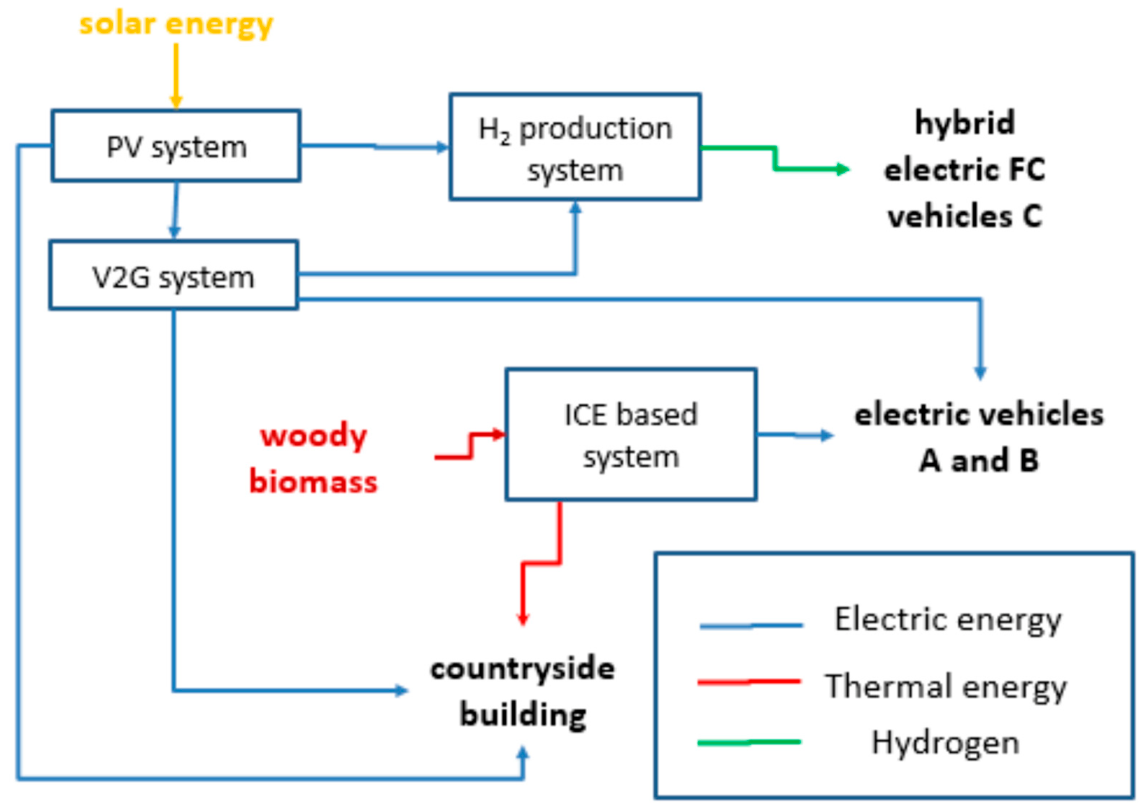
Figure 3.
Time trends of the electric power produced by PV plant in the four seasons’ typical days.
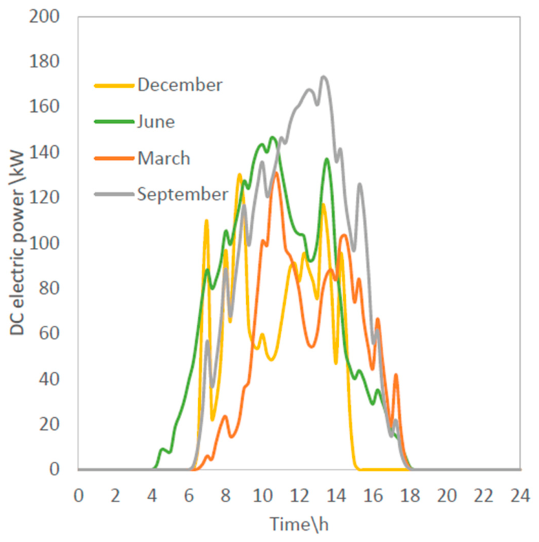
Figure 4.
Thermal and electric efficiencies of the internal combustion engine as a function of the percentage of rated electric power.
Figure 4.
Thermal and electric efficiencies of the internal combustion engine as a function of the percentage of rated electric power.
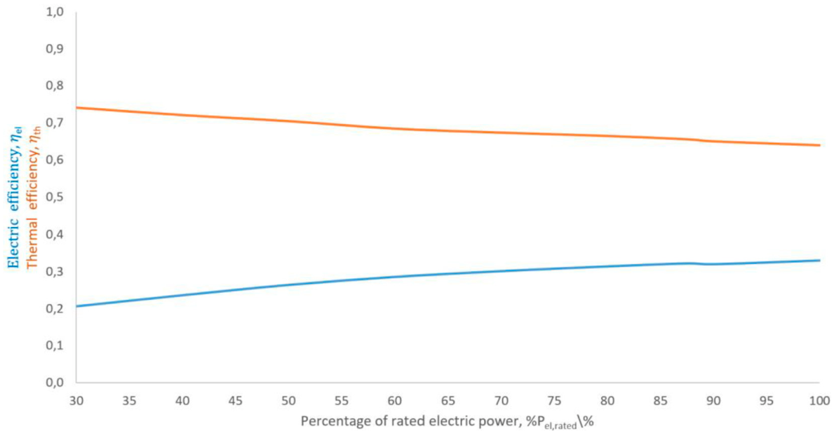
Figure 6.
Time trends of the electric and thermal powers produced by the poly-generative system in winter/spring day (a), in summer day (b) and in autumn day (c) and time trend of the hydrogen mass (d) produced by the same poly-generative system in maximum and minimum range conditions.
Figure 6.
Time trends of the electric and thermal powers produced by the poly-generative system in winter/spring day (a), in summer day (b) and in autumn day (c) and time trend of the hydrogen mass (d) produced by the same poly-generative system in maximum and minimum range conditions.
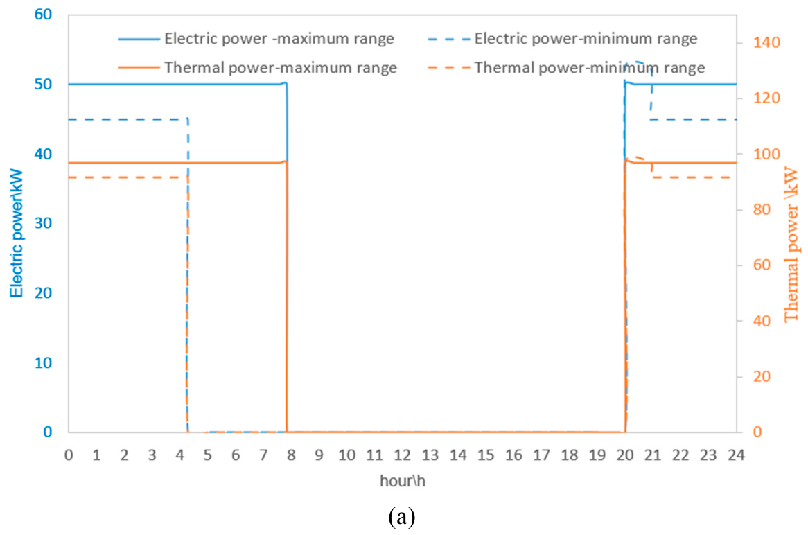
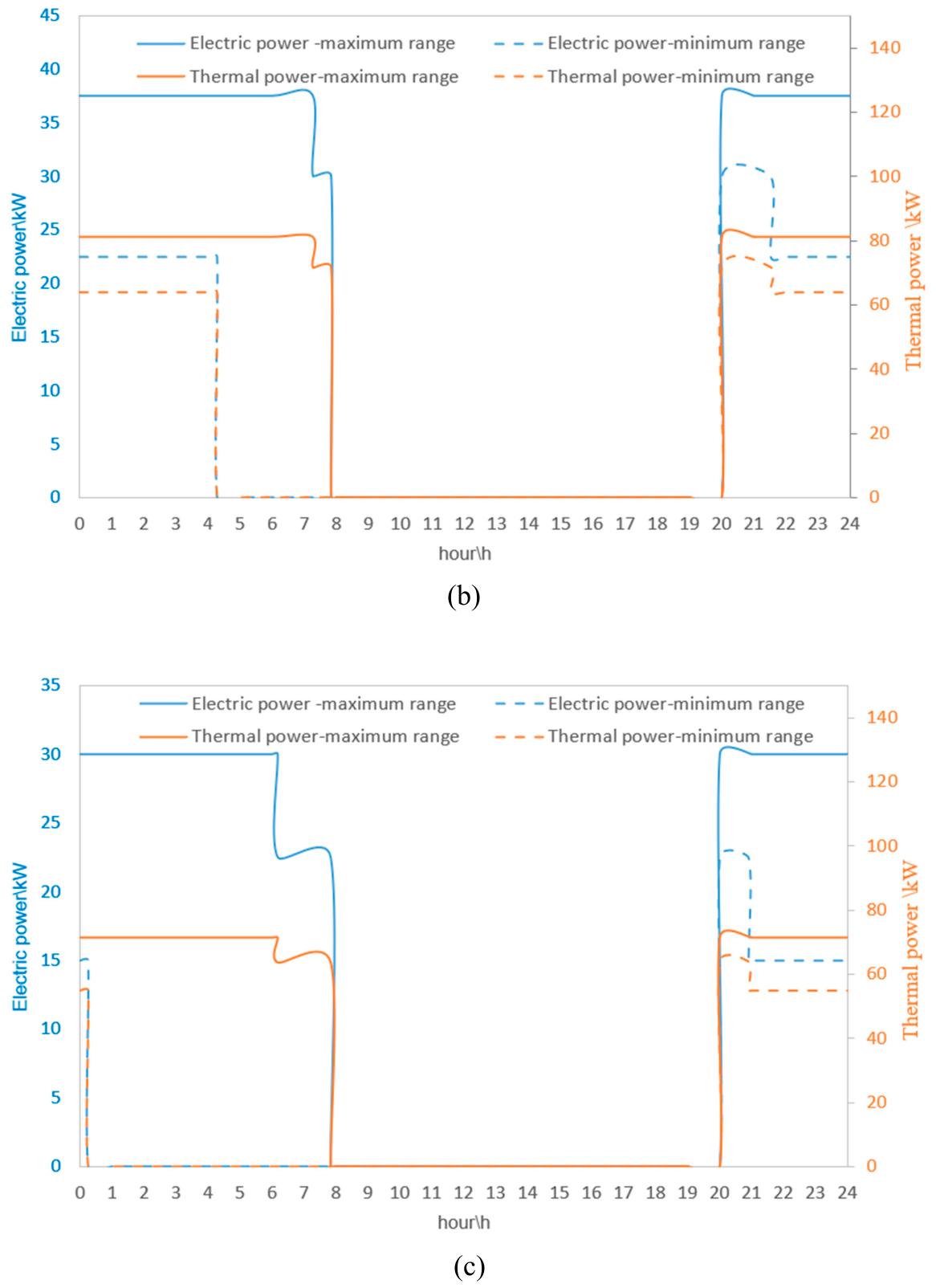
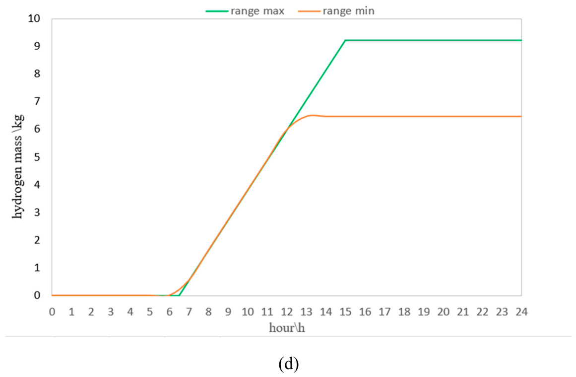

Table 1.
Type, number and average travelled distances of the vehicles.
| Vehicles Type | Vehicles number | Distance/km |
|---|---|---|
| A | 15 | 45.1 |
| B | 12 | 299 |
| C | 3 | 389 |
Table 2.
Input parameters of the PEM Electrolyzer dynamic electric model, including the PEM Electrolytic stack and DC-DC buck converter models.
Table 2.
Input parameters of the PEM Electrolyzer dynamic electric model, including the PEM Electrolytic stack and DC-DC buck converter models.
| Input Parameters | Unit | Values |
|---|---|---|
| DC-DC buck converter | ||
| Pel,DC,in | kW | 71 |
| fsw | Hz | 1000 |
| L1 | H | 0.107 |
| Rin1 | 0.02 | |
| Rout1 | 0.002 | |
| Cin1 | F | 0.023 |
| Cout1 | F | 4.62 × 10⁻⁵ |
| Cstab2 | F | 0.02 |
| PEM electrolytic short stacks | ||
| Nss | - | 360 |
| Nc | - | 3 |
| Iss,min | A | 4.5 |
| Rid (Iss,min) | 0.8299 | |
| DRid (Iss) | −0.5723 | |
| Ran (Iss,min) | 0.0119 | |
| DRan (Iss) | −0.0073 | |
| Rmem (Iss,min) | 0.1607 | |
| DRmem (Iss) | −0.0001 | |
| Rcat (Iss,min) | 0.0465 | |
| DRcat (Iss) | −0.0294 | |
| Ccat | F | 0.05 |
| Can | F | 0.05 |
Disclaimer/Publisher’s Note: The statements, opinions and data contained in all publications are solely those of the individual author(s) and contributor(s) and not of MDPI and/or the editor(s). MDPI and/or the editor(s) disclaim responsibility for any injury to people or property resulting from any ideas, methods, instructions or products referred to in the content. |
© 2026 by the authors. Licensee MDPI, Basel, Switzerland. This article is an open access article distributed under the terms and conditions of the Creative Commons Attribution (CC BY) license (http://creativecommons.org/licenses/by/4.0/).
Copyright: This open access article is published under a Creative Commons CC BY 4.0 license, which permit the free download, distribution, and reuse, provided that the author and preprint are cited in any reuse.


