

Submitted:
27 June 2026
Posted:
30 June 2026
You are already at the latest version
Abstract
Accurate prediction of gypsum-salt cap rocks is crucial for safe drilling and efficient development of subsalt hydrocarbons in the Tarim Basin. However, due to the complex lithological assemblages within the Middle Cambrian sequences, the P-impedance of gypsum severely overlaps with that of the background carbonate rocks, making conventional seismic prediction based on a single impedance threshold inadequate. To address this issue, we propose a multi-parameter coupling while-drilling prediction method that integrates seismic data, drilling parameters and geochemical logging. First, pre-stack P-impedance inversion is performed on amplitude-preserved seismic data to macroscopically delineate the depth interval of gypsum-salt development. Second, a weighted synthetic change-rate model incorporating rate of penetration (ROP), weight on bit (WOB) and outlet conductivity is constructed to dynamically calibrate the top interface of the gypsum-salt layer while drilling. Finally, within the constrained depth interval, X-ray fluorescence (XRF) elemental inversion of cuttings is used to quantitatively calculate the contents of clay, dolomite, gypsum and calcite, achieving fine-scale lithofacies identification at the sub-layer level. An empirical application to Well XSC1 in the Keping fault-uplift, Tarim Basin, demonstrates that compared with the conventional single P-impedance threshold method, the proposed approach effectively distinguishes gypsum, halite and carbonate wall rocks, and significantly reduces the prediction errors of individual salt beds and gypsum sublayers. Specifically, the mean absolute error (MAE) of total gypsum-salt content decreases from 24.56% to 13.73% (a reduction of 44.1%), the bias drops from 2.45% to 0.31%, and the root mean square error (RMSE) decreases from 33.63% to 21.55%. At a 1% content threshold, the F1 score for gypsum-salt identification increases from 0.63 to 0.82; the absolute depth error of the top and bottom interfaces is reduced by approximately 70%, and the relative thickness error shrinks from ±40% to within ±10%. This multi-parameter coupling strategy provides an engineering-ready, high-precision technical pathway for deep Cambrian subsalt exploration in salt-bearing basins of central-western China.
Keywords:
Cambrian
; Gypsum-salt rocks
; multi-parameter coupling
; p-impedance overlap
; prediction while drilling
; Tarim Basin
1. Introduction
Gypsum-salt rocks are mainly developed in inland salt lakes, barrier lagoons and restricted bays under arid climatic conditions. Their formation is controlled by chemical sedimentary differentiation during evaporation and concentration of semi-restricted to restricted water bodies. Experimental petrology indicates that when seawater is evaporated and concentrated to 15%–17% of its initial volume, gypsum-type minerals begin to precipitate; at approximately 26% concentration, halite starts to crystallize. This process generates gypsum-salt sequences dominated by gypsum, anhydrite and halite, often interbedded with carbonate rocks (limestone, dolomite, marl, etc.) [1,2,3]. Owing to their low porosity, low permeability and high ductility, such rocks are generally regarded as high-quality regional seals in petroliferous basins worldwide. Statistics show that about 58% of global oil and gas fields are related to gypsum-salt rocks, among which 46% of hydrocarbon reserves occur below gypsum-salt layers and 13% occur between them. Among the 165 gas fields proven in China, about 40% are controlled by gypsum-salt rocks, and their natural gas reserves account for approximately 36% of the national total [4]. The Lower–Middle Cambrian of the Tarim Basin extensively develops gypsum-salt cap rocks, with enormous subsalt hydrocarbon potential: estimated petroleum and natural gas in-place resources are approximately 90.52 108 t and 10.24 1012 m3, respectively, with an overall proven rate of only about 18%, indicating a broad exploration prospect [4,5,6].
Although gypsum-salt rocks as high-quality seals bring significant benefits for hydrocarbon accumulation, their unique rock mechanical behavior poses severe challenges to drilling engineering. During drilling, gypsum-salt rocks are prone to creep, collapse, hydration swelling and hole shrinkage. Moreover, the significant differences in pressure systems among supra-salt, inter-salt and sub-salt strata easily induce major drilling incidents such as pipe sticking, lost circulation, kick or even blowout, resulting in extremely high well control risks [7,8,9,10,11]. The Middle Cambrian gypsum-salt sequences in the Tarim Basin lack a stable sedimentary model; the top and bottom of the gypsum-salt layer are both dolomite, with no regionally correlatable marker beds [5]. Lateral thickness variations are severe, making it extremely difficult to predict both individual bed and cumulative thickness. From a geophysical attribute perspective, halite exhibits distinctly low interval transit time (about 220 s/m) and low density (about 2030 kg/m3), which can be effectively distinguished from limestone (about 156 s/m, 2710 kg/m3) and dolomite (about 143 s/m, 2870 kg/m3). Therefore, P-impedance inversion is commonly used for identification. However, the P-wave velocity and density of gypsum and anhydrite (anhydrite: about 164 s/m, 2980 kg/m3; gypsum: about 174 s/m, 2350 kg/m3) overlap significantly with those of background carbonate rocks, so a single P-impedance threshold cannot accurately differentiate gypsum from carbonates [12,13,14]. In addition, conventional post-stack seismic inversion is limited by AVO effects and finite bandwidth, resulting in limited vertical resolution, and its prediction accuracy cannot meet the requirements of fine drilling.
In terms of prediction while drilling, techniques such as chemical reagent testing on cuttings and X-ray fluorescence (XRF) elemental analysis have been applied to gypsum-salt identification [15,16,17,18]. However, XRF analysis results are greatly affected by the representativeness of cuttings, the accuracy of sampling depth, and the dissolution of halite in under-saturated mud systems. Moreover, full-hole XRF analysis is costly and time-consuming, making it difficult to achieve real-time, economical and reliable discrimination while drilling. Therefore, conventional methods relying solely on seismic inversion or mud logging have their inherent limitations, and there is an urgent need to establish an integrated prediction strategy that fuses multi-source information and incorporates dynamic while-drilling calibration.
To address this challenge, this paper proposes a comprehensive prediction method for Cambrian gypsum-salt rocks integrating seismic, drilling and logging parameters. The method is based on P-impedance data obtained from pre-stack elastic parameter inversion, which is used to macroscopically determine the depth interval of gypsum-salt development before drilling and to optimize well design. During drilling, a weighted synthetic change-rate index of WOB, ROP and outlet conductivity is introduced to dynamically calibrate the top interface of the gypsum-salt layer. Within the predicted depth range, combined with cuttings observation and X-ray elemental quantitative analysis, a fine lithological discrimination model based on mineral content calculation is established. Taking Well XSC1 in the Keping fault-uplift at the northwestern margin of the Tarim Basin as an example, we compare the conventional method and the proposed method in terms of the identification accuracy of gypsum and halite sublayers and the positioning of top and bottom interfaces, aiming to provide an engineering-ready technical pathway for deep to ultra-deep hydrocarbon exploration in salt-bearing basins of central-western China.
2. Geological Setting
2.1. Regional Tectonic and Depositional Evolution
The Tarim Basin is a large composite superimposed basin in western China. Its Cambrian tectonic-depositional evolution experienced a significant transition from deep-water shelf to restricted platform. During the Early Cambrian, influenced by a large-scale marine transgression, the basin mainly developed deep-water basinal and slope facies of argillaceous carbonate rocks and siliceous rocks, depositing thick, high-quality marine source rocks [19,20]. Subsequently, the basin rapidly evolved into a restricted platform environment dominated by dolomite flats and mound-shoal facies. By the Middle Cambrian, under the coupled control of a global sea-level fall and regional arid climate, the central-western Tarim Basin entered an intense evaporite development stage. Salinity increased significantly, forming a strongly rimmed carbonate platform dominated by evaporative lagoons and sabkhas [5]. During this stage, a set of gypsum-salt sequences consisting mainly of gypsum, anhydrite and halite, frequently interbedded with dolomite and mudstone, was deposited. These sequences are widely distributed in the central-western part of the basin (covering an area of about 24 104 km2) and, together with the underlying Lower Cambrian source rocks and the overlying carbonate reservoirs, constitute an excellent source-reservoir-seal assemblage with huge hydrocarbon potential [19,20,21,22].
2.2. Local Structural and Stratigraphic Characteristics of the Keping Uplift
The study area is located in the eastern segment of the Keping fault-uplift at the northwestern margin of the Tarim Basin (Figure 1a–c). The Keping fault-uplift is a long-term inherited paleo-high, surrounded by three hydrocarbon-generating depressions (Awati, Baicheng and Wushi) providing favorable conditions for hydrocarbon accumulation. Structurally, this area develops the only thin-skinned thrust structure in the basin and its periphery that uses the Middle Cambrian gypsum-salt layer as a detachment plane. The gypsum-salt layer acts both as a detachment surface and as a high-quality regional seal. In recent years, Well KT1 obtained a high-yield industrial gas flow of 1.04 106 m3/day from the subsalt argillaceous dolomite of the Wusonger Formation (3686–3698 m) [11], confirming the broad prospect of Cambrian subsalt exploration in this area.
The target gypsum-salt interval is mainly developed in the Middle Cambrian Shayilik (s) and Awatag (a) formations, and the lithological assemblage is characterized by complex thin interbeds of dolomite, gypsum, halite and mudstone (Figure 1d). Individual salt beds are generally 1–20 m thick, and the cumulative thickness varies drastically laterally (10–160 m). Both the top and bottom of the sequence are in direct contact with dolomite, lacking stable regional marker beds. More critically, drilling has revealed a complex pressure system: a high-pressure brine layer is often developed at the top of the Shayilik Formation, with a pressure difference of up to 0.8–1.0 MPa relative to the gypsum-salt interval. This superposition of complex lithological assemblages and multiple pressure systems makes it very easy to encounter creep-induced hole shrinkage, lost circulation or kicks when drilling through the gypsum-salt rocks, imposing extremely high engineering requirements for accurate prediction of the spatial distribution and the depths of the top and bottom interfaces of the gypsum-salt layer.
2.3. Challenges in Gypsum-Salt Prediction
From the perspective of geophysical identification, the prediction of gypsum-salt sequences faces inherent petrophysical non-uniqueness. A cross-plot of density versus P-wave velocity for typical Cambrian lithologies in the northwestern Tarim Basin (Figure 2a) shows that halite concentrates in the low-density (2030 kg/m3) and low-velocity (220 s/m) domain, with a mean P-impedance of approximately 9.2 106 kg/(m3⋅m/s), making it generally separable from carbonate rocks. However, the physical properties of gypsum and anhydrite severely overlap with those of background carbonates: anhydrite has a density of up to 2980 kg/m3, gypsum 2350 kg/m3, and their P-wave velocities are comparable to those of limestone (2710 kg/m3) and dolomite (2870 kg/m3).
Quantitative characterization using an impedance overlap matrix (Figure 2b) further reveals this non-uniqueness: the impedance overlap coefficients of gypsum with dolomite and limestone are as high as 0.85 and 0.70, respectively, while the overlap coefficient between dolomite and limestone is also 0.75. Consequently, conventional seismic inversion based on a single P-impedance threshold can effectively delineate low-impedance salt-rich intervals but cannot resolve the non-uniqueness between gypsum and carbonate rocks. In intervals where transitional lithologies such as gypsiferous dolomite and dolomitic gypsum are developed, single-impedance discrimination is highly prone to omissions and misjudgments. Statistics indicate that between 2016 and 2022, the rate of sidetracking due to inaccurate prediction of gypsum-salt layers in the northwestern Tarim Basin exceeded 90%. Evidently, constrained by the overlap of petrophysical attributes, the fine prediction of gypsum-salt sequences must transcend the limitations of single-parameter thresholds and shift towards multi-scale, multi-parameter joint prediction mechanisms.
3. Methodology
We propose a three-stage progressive integrated prediction method that fuses seismic, drilling and logging parameters (Figure 3). First, pre-stack elastic inversion is used to obtain the macroscopic depth interval of gypsum-salt rocks. Second, a synthetic change-rate model of drilling parameters is used to lock the top interface while drilling. Finally, XRF elemental logging is employed to quantitatively invert mineral end-members and achieve fine lithological characterization.
3.1. P-Impedance Prediction Based on Pre-Stack Elastic Inversion
To overcome the resolution limitations of conventional post-stack inversion caused by AVO effects and bandwidth restrictions, pre-stack elastic parameter inversion based on amplitude-preserved gather data is first used to preliminarily delineate the gypsum-salt development interval. This method is based on the Aki-Richards equation, and Gidlow et al. (1992) [23,24] provided an approximate form expressed in terms of impedance reflection coefficients:
where is the P-wave reflection coefficient; , , are the P-wave reflection coefficient, S-wave reflection coefficient and density gradient, respectively; and , , are angle-dependent coefficients. Furthermore, the approximation method of Walker and Ulrych (1983) [25] is adopted to convert the reflection coefficient expression into elastic parameters of the formation, achieving parameter discretization. A linear inversion system is established:
where is the multi-angle seismic observation data, is the vector of unknown P-impedance, S-impedance and density parameters, is the kernel function matrix composed of wavelet matrix and partial derivative coefficients, and is the noise term. By introducing an initial low-frequency model constraint, a damped least-squares method is used to solve the objective function, obtaining a high-fidelity P-impedance () volume [11,12].
Because of the low-impedance character of halite and the impedance overlap between gypsum and carbonates, at this stage the pre-stack inversion is used only to provide a depth-window constraint (), macroscopically locking the depth interval of gypsum-salt development before drilling to optimize casing design.
3.2. Dynamic Identification of the Top Interface of Gypsum-Salt Layers Using a Synthetic Change Rate of Drilling Parameters
Limited by the seismic frequency band, the positioning accuracy of the top interface of gypsum-salt rocks from pre-stack inversion still has errors of several meters to tens of meters. To address this, we propose a weighted synthetic change-rate method based on rate of penetration (ROP), weight on bit (WOB) and outlet conductivity to achieve real-time dynamic calibration of the top interface of the gypsum-salt layer during drilling. The synthetic change rate at depth is defined as:
where , and are ROP, WOB and outlet conductivity, respectively; are weight coefficients (with ; in this study equal weights of are used). The physical mechanism of this model is that when the drill bit transitions from brittle carbonate rocks into ductile gypsum-salt rocks, the sudden change in rock drillability causes and to decrease synchronously, while halite dissolution/gypsum hydration causes to increase sharply. A significant peak in can effectively indicate the top interface of the gypsum-salt layer. Similarly, when the drill bit exits the gypsum-salt layer and enters the underlying carbonate rocks, and increase sharply and decreases, forming a reverse anomaly that helps constrain the bottom interface. In practice, is continuously calculated within a window of 50 m above and below the depth predicted by inversion; when it exceeds the background value by a factor of 3–5, subsequent XRF intensive sampling is triggered.
3.3. Quantitative Inversion of Mineral Contents Based on XRF Elemental Logging
Within the depth window established by the above dual constraints, cuttings-based XRF elemental logging is used to compensate for the insufficient end-member resolution of geophysical parameters. Under the under-saturated saltwater mud system, the primary diagnostic criterion is: if no cuttings are returned, the interval is directly classified as a halite layer. For returned cuttings, mineral contents are calculated sequentially based on the mineral stoichiometry in Table 1 to resolve the non-uniqueness caused by shared elements (e.g., Ca, S):
Clay content (based on the proxy element Al):
Dolomite content (based on the proxy element Mg, subtracting Mg in clays):
Gypsum content (based on the proxy element S, subtracting S in pyrite):
Calcite content (based on residual Ca allocation):
where are the measured contents of Al, Mg, S, and Ca at depth , respectively. This sequential calculation strategy explicitly cuts off the geophysical non-uniqueness between carbonates and gypsum caused by impedance overlap, achieving microscopic fine splitting of lithofacies end-members.
4. Results
To verify the effectiveness of the proposed multi-parameter coupling prediction method, Well XSC1 in the Keping Uplift, Tarim Basin, was selected as the empirical target. A systematic comparison of prediction accuracy was conducted between the conventional single-impedance-threshold method and the proposed approach.
4.1. Gypsum-Salt Sequence Identification
Pre-stack elastic inversion was performed on amplitude-preserved seismic gather data, combined with interpreted horizons and well-log information from adjacent wells to build a low-frequency model, yielding a P-impedance volume. The seismic section and inverted P-impedance section across Well XSC1 (Figure 4) show that low-impedance zones (white to green) are discontinuously distributed vertically, preliminarily indicating possible gypsum-salt intervals in the Middle Cambrian. Extracting the P-impedance curve along the wellbore and applying a regional rock-physics threshold (P-impedance 1.45 107 kg/(m3⋅m/s)), the probable depth range of gypsum-salt rocks was initially delineated as 3900–4800 m (Figure 5e).
During drilling, parameters including ROP, WOB and outlet conductivity were systematically recorded, and the synthetic drilling parameter change rate was calculated (with equal weights ). As shown in Figure 5, at a depth of approximately 3935 m, the outlet conductivity increased sharply, while ROP and WOB decreased synchronously with persistent fluctuations. The synthetic change rate jumped from a background value of 0.2% to 6.8%, forming a distinct peak that indicates entry into the gypsum-salt interval. This depth is generally consistent with the top interface predicted by P-impedance inversion but with higher resolution.
Under the unsaturated brine drilling fluid system, X-ray fluorescence (XRF) analysis was performed on cuttings from the target interval. Mineral contents (clay, dolomite, gypsum, calcite, etc.) were quantitatively calculated using Equations (5)–(8), allowing lithology discrimination. Figure 6 compares the results of the conventional method and the proposed method. The conventional P-impedance threshold method (Figure 6b) only roughly delineates low-impedance intervals, fails to distinguish specific lithologies (gypsum, halite, mudstone, etc.), and has limited depth resolution. In contrast, the proposed method integrates the drilling parameter change rate (Figure 6a), XRF elemental data (Figure 6c) and quantitative mineral calculations, and the final lithology column (Figure 6d) achieves fine identification of six lithologies (gypsum, halite, mudstone, sandstone, limestone, dolomite) and their combinations. Specifically, near 3935 m, both P-impedance and the synthetic change rate show anomalies, and XRF further confirms this interval as gypsiferous argillaceous dolomite. In the depth interval 4300–4710 m, P-impedance decreases significantly and the synthetic change rate exhibits abundant anomalies, which is interpreted as the main gypsum-salt development zone, where eight individual halite interbeds are precisely recognized.
4.2. Accuracy Evaluation
Using post-drilling open-hole log interpretations as the reference standard, quantitative error statistics were calculated for both conventional seismic prediction and the proposed method. Figure 7 shows that conventional seismic prediction only provides a continuous envelope of total gypsum-salt content, which exhibits a smooth, broad-band character over the 3900–4900 m interval, fails to separate gypsum and halite end-members, and yields false-positive responses in the upper weak-gypsum-salt section and the lower carbonate section. In contrast, the integrated prediction (Figure 8) simultaneously outputs gypsum, halite and total gypsum-salt contents, showing good agreement with log interpretations in the gypsum-dominated interval (4200–4330 m), the halite-dominated interval (4330–4540 m), and the gypsum-salt interbedded interval (4600–4750 m).
The depth-by-depth error structure and statistical metrics confirmed a substantial improvement in accuracy (Figure 9, Table 2). The conventional seismic prediction of total gypsum-salt content yielded a mean absolute error (MAE) of 24.56% and a root mean square error (RMSE) of 33.63%, with local depth errors fluctuating by over 50% (Figure 9b). Following the integrated prediction, the total content error curve converged significantly toward zero (Figure 9c), with MAE decreasing to 13.73% (a reduction rate of 44.1%) and RMSE to 21.55%, and the systematic bias dropping from 2.45% to 0.31%. Furthermore, 70.2% of the paired depth points showed improved absolute errors. Regarding component errors, halite prediction achieved the highest precision (median absolute error of 0.00%, Figure 9e), while gypsum errors were primarily concentrated in the gypsiferous dolomite transition zones (Figure 9d).
5. Discussion
5.1. Prediction Accuracy and Classification Evaluation
At a 1% content threshold, the presence or absence of the target lithology is treated as a binary classification problem. Taking the post-drilling open-hole log interpretation as the reference standard, the accuracy, precision, recall, and F1 score are computed for all four prediction targets (conventional seismic gypsum-salt, integrated gypsum-salt, integrated gypsum, and integrated salt) and are summarized in Table 3, with the corresponding binary confusion matrices presented in Figure 10a–d. The results show that although conventional seismic prediction has a very high recall (1.00), its precision is only 0.46, with 534 false-positive samples, indicating a clear tendency to over-predict. This is mainly due to the overlap coefficient of 0.70–0.85 in P-impedance between gypsum and carbonate rocks, which makes a single impedance threshold ineffective for differentiation.
In contrast, the integrated prediction method increases the precision to 0.70, and the F1 score increases from 0.63 to 0.82. The identification stability for the halite end-member is the highest (precision 0.98, F1 score 0.85), benefiting from its uniquely low impedance and low density, as well as sensitive responses in conductivity and Cl element. The identification accuracy for the gypsum end-member is lower (precision 0.58, F1 score 0.69), mainly due to the mixed responses in the transitional zones of gypsiferous dolomite and dolomitic gypsum. Clearly, without sacrificing detection rate, the proposed method significantly reduces the false-positive rate and improves the engineering usability of the predictions.
5.2. Petrophysical and Engineering Mechanisms of Multi-Parameter Coupled Response
The key reason why the proposed multi-parameter coupling prediction method significantly improves accuracy lies in its utilization of the differences in multi-scale characteristic responses when drilling through gypsum-salt sequences. At the petrophysical scale, although the P-impedance of anhydrite overlaps with that of carbonate rocks, there are significant differences in mechanical properties: gypsum is more ductile, while halite exhibits pronounced rheological behavior. When the drill bit transitions from brittle carbonate rocks into ductile gypsum-salt rocks, the drillability changes abruptly, causing significant variations in ROP and WOB. This is the physical basis of the synthetic drilling parameter change-rate model. At the geochemical scale, XRF elemental analysis directly reflects the chemical characteristics of mineral components, effectively compensating for the insufficient resolution of geophysical parameters. The coupling of these “mechanical-chemical” dual attributes gives the method an unparalleled advantage in recognizing thin interbeds.
5.3. Potential Error Sources and Improvement Measures
Based on the empirical evidence from Well XSC1, the method has limitations in the following three dimensions that require optimization in future studies:
(1) Quantitative compensation for cuttings representativeness: In undersaturated saltwater systems, salt dissolution leads to “zero returns” of cuttings, relying on the qualitative criterion of “no cuttings + high conductivity.” Future work should introduce LithoScanner technology to acquire in-situ elements to correct depth deviations in cuttings retrieval, and transform the “dissolution effect” from a qualitative marker into a quantitative ion concentration-depth mapping model.
(2) Dynamic correction for parameter lag effects: Parameters such as outlet conductivity exhibit time lag accumulating with circulation depth, affecting the precision of bottom interface determination in ultra-deep wells. It is recommended to introduce a depth-shift correction algorithm based on cycle time, or utilize cross-correlation analysis between short-lag parameters (e.g., torque) and long-lag parameters (conductivity) to achieve dynamic alignment of interfaces.
(3) Regional adaptability of the equal-weight model: The current model employs equal weights (), which obscures parameter sensitivity differences under varying drilling technologies (e.g., differences in rock-breaking mechanisms between PDC and roller-cone bits). Future efforts should quantify parameter contribution weights using algorithms like Random Forest based on historical well data, constructing an adaptive change rate model that dynamically adjusts with drilling conditions.
5.4. Engineering Application Prospects
Compared with full-wellbore XRF logging, the proposed “seismic delineation drilling-parameter locking XRF identification” three-step strategy offers significant economic advantages. The synthetic drilling parameter change rate, as a real-time, low-cost data source, acts as a “trigger” that initiates expensive XRF analysis only when anomalies occur. In the application to well XSC1, this strategy reduced the interval requiring detailed elemental analysis by approximately 40 %, substantially lowering exploration costs. The method is not only technologically advanced but also economically viable, making it suitable for large-scale deployment in deep, salt-bearing basins of central-western China (e.g., Sichuan, Ordos, and Qaidam basins, which have similar sedimentary-tectonic-pressure conditions). Furthermore, its success provides a transferable multi-parameter integration approach for predicting other complex lithologies (e.g., shales, basalts).
6. Conclusions
1. The Middle Cambrian gypsum-salt sequences in the northwestern Tarim Basin face severe geophysical non-uniqueness, with a P-impedance overlap coefficient of up to 0.85 between gypsum and carbonate rocks. This study confirms that conventional prediction methods based on a single P-impedance threshold have inherent limitations, exhibiting an extremely high false positive rate (precision of only 0.46), which fails to meet the engineering requirements for safe drilling in thin interbed zones.
2. The proposed synthetic drilling parameter change rate (a weighted combination of ROP, WOB and outlet conductivity) rapidly responds to abrupt changes in drillability, creep behavior and ion concentration fluctuations when drilling through gypsum-salt sequences, effectively locating the top interface of the salt-gypsum layer. This method offers strong real-time capability and can dynamically calibrate seismic predictions, significantly improving interface positioning reliability.
3. The established seismic-drilling-logging multi-parameter coupling prediction method organically integrates pre-stack elastic parameter inversion, while-drilling drilling parameter analysis, and quantitative XRF elemental inversion. The empirical application shows that the method reduces the absolute depth error of the top and bottom interfaces by approximately 70%, shrinks the relative thickness error from 40% to within 10%, decreases the MAE of total gypsum-salt content from 24.56% (conventional method) to 13.73%, reduces bias from 2.45% to 0.31%, and lowers RMSE from 33.63% to 21.55%. At the 1% content threshold, the integrated prediction increases the F1 score from 0.63 to 0.82 and precision from 0.46 to 0.70, significantly reducing the false-positive rate without sacrificing detection rate.
4. The successful application of this method to Well XSC1 in the Keping fault-uplift, Tarim Basin, demonstrates its effectiveness and engineering adaptability in complex gypsum-salt sequences. This work provides a transferable technical framework for deep to ultra-deep Cambrian subsalt exploration in salt-bearing basins of central-western China (e.g., the Sichuan, Ordos and Qaidam basins, which have similar sedimentary-tectonic-pressure conditions), with significant engineering value and scientific implications for reducing drilling risks, protecting reservoirs, and improving exploration efficiency.
Funding
This work was jointly supported by the National Major Project of China (Grant No. 2025ZD1010303), the Special Project of the Department of Science and Technology of Inner Mongolia Autonomous Region (Grant No. KCX2024003), the projects of the China National Petroleum Corporation (Grant Nos. 2024DJ93), and China Geological Survey Projects (Grant No. DD20241675).
Conflicts of Interest
The authors declare no conflicts of interest.
References
- Wu, X.Q.; Yang, W.; Bo, D.M.; Ji, T.Y.; Dong, C.Y.; Luan, T.S.; Qu, J.Y. Research on lithofacies paleogeography and caprock evaluation of the Middle Cambrian in the Tarim Basin, NW China. Appl. Sci. 2024, 14, 9372. [CrossRef].
- Liao, Q.F.; Han, Y.; Wu, G.P.; He, Q.; Li, J.; Liu, B.; Shi, K.B. Diagenetic evolution of gypsum-salt rocks of Lower and Middle Cambrian in Tarim Basin and its impact on subsalt reservoir development. Exp. Pet. Geol. 2025, 47, 1241–1254.
- Shi, S.Y.; Hu, S.Y.; Liu, W.; Wang, T.S.; Zhou, G.; Xu, A.; Huang, Q.Y.; Xu, Z.H.; Hao, B.; Wang, K.; Jiang, H.; Ma, K.; Bai, Z.Z. Hydrocarbon accumulation in deep ancient carbonate–evaporite assemblages. Pet. Explor. Dev. 2024, 51, 54–68. [CrossRef].
- Hu, A.P.; Shen, A.J.; Yang, H.X.; Zhang, J.; Wang, X.; Yang, L.; Meng, S.X. Dolomite genesis and reservoir-cap rock assemblage in carbonate-evaporite paragenesis system. Pet. Explor. Dev. 2019, 46, 916–928. (In Chinese).
- Fan, Q.; Fan, T.L.; Li, Q.P.; Du, Y.; Zhang, Y.; Yuan, Y.X. Sedimentary characteristics and development model of Cambrian gypsum-salt rocks, Tarim Basin. Pet. Geol. Exp. 2021, 43, 217–226. (In Chinese).
- Bian, Q.; Zhang, J.B.; Feng, F.; Li, Y.; Huang, C.J.; Wang, T.Y.; Guo, K.K. Sedimentary distribution of evaporites in Wusongge’er Formation in central Tarim Basin and reconstruction of prototype basin. J. Palaeogeogr. 2025, 100296. [CrossRef].
- Tang, G.; Zhao, C.J.; Li, J.; Zhang, X.; Guo, J.H.; Lei, X.M. Borehole diameter variation characteristics of gypsum-salt rocks effected by drilling fluid. Drill. Prod. Technol. 2020, 43, 24–27+7. (In Chinese).
- Qiu, Y.F. Study on Deformation Mechanism and Anti-creep Countermeasure of Composite Salt Layer. Ph.D. Thesis, China University of Petroleum-Beijing, Beijing, China, 2021. (In Chinese).
- Nie, Z.; Zhang, Z.Y.; Luo, H.H.; Zou, K. Key technologies for directional well drilling in high-pressure anhydrite salt layers. Nat. Gas Ind. 2018, 38, 103–110. (In Chinese).
- Lin, H.; Deng, J.G.; Xu, J.; Xie, T.; Liu, H.L. Borehole shrinkage mechanism and countermeasure analysis of composite salt-gypsum layer. Fault-Block Oil Gas Field 2018, 25, 793–798. (In Chinese).
- Zhou, M.; Bai, H.P.; Chen, Y. Acid plugging removal technology and application effect of Well Ketan1 in Keping Fault Uplift Zone, Tarim Basin. Shanxi Chem. Ind. 2022, 42, 150–152. (In Chinese).
- Trippetta, F.; Collettini, C.; Vinciguerra, S.; Meredith, P.G. Laboratory measurements of the physical properties of Triassic Evaporites from Central Italy and correlation with geophysical data. Tectonophysics 2010, 492, 121–132.
- Li, H. Prestack seismic prediction technique for ultra-deep carbonate reservoirs in Shunbei field. Geophys. Prospect. Pet. 2025, 64, 736–748. [CrossRef].
- Li, H.; Yin, H.W.; Tang, J.L.; Xiao, P.F. Application of AVO Characteristics Analysis and Seismic Dispersion AVO Inversion to the Carbonate Hydrocarbon Reservoirs in Region Y of the Tarim Basin, China. Geofluids 2024, 2024, 3034459. [CrossRef].
- Vidal Soares de Oliveira, F.C.S.R.; Tepedino Martins Gomes, R.; Dias Roriz, C.E.; Milani Simões Silva, K.; Correa de Toledo, R. Lithology identification through X-Ray fluorescence (XRF) analyses on drill cuttings while drilling, in Santos Basin. In Proceedings of the SPE Annual Technical Conference and Exhibition; SPE: Houston, TX, USA, 2022; p. D021S027R005. [CrossRef].
- Liu, J.; Luo, G.; Wang, M.W. Stress field and safe drilling mud weights in the Shizigou salt system of Yingxiongling, Qaidam Basin, China. J. Pet. Explor. Prod. Technol. 2025, 15, 48. [CrossRef].
- Huan, Z.P.; Hu, J.F.; Wang, Z.M.; Song, J.P.; Mo, T.; Hao, X.B.; Tian, P.P.; Cui, D.Y.; Yang, J.B.; Li, H.P.; Liu, X.Y.; Ping, Z.W. Research and application of the base salt rock discrimination of the Paleogene in Kuqa Depression. China Pet. Explor. 2022, 27, 142–150. (In Chinese).
- Yang, B.Z.; Li, G.; Liu, N.; Ma, T.F.; Zhou, P.Y.; Wang, J.C.; Tan, J.P. Salt bottom determination technology of Kuqa Depression, Tarim Basin. Mud Logging Eng. 2021, 32, 124–129. (In Chinese).
- Ji, T.Y.; Yang, W.; Wu, X.Q.; Pu, R.H.; Li, D.J.; Liu, M.C.; Miao, W.D.; Su, N.; Ye, Y. Evaluation of Cambrian caprock in the platform-basin area of Tarim Basin and optimization of favorable area for oil and gas caprock. Geol. China 2022, 49, 369–382.
- Liu, L.H.; Gao, Y.J.; Wang, D.D.; Bai, Z.K.; Zhang, Y.Y.; Han, M. The impact of gypsum salt rock on Cambrian subsalt dolomite reservoir in the Tarim Basin. Acta Petrol. Mineral. 2021, 40, 109–120.
- Wang, Q.H.; Chen, Y.Q.; Hu, F.J. Cap rock in Lower Paleozoic carbonate rocks and its controls over hydrocarbon accumulation, Tarim Basin: Case study from the western Tarim carbonate platform. Nat. Gas Geosci. 2023, 34, 1–14.
- Yang, H.J.; Chen, Y.Q.; Tian, J.; Du, J.H.; Zhu, Y.F.; Li, H.H.; Pan, W.Q.; Yang, P.F.; Li, Y.; An, H.T. Great discovery and its significance of ultra-deep oil and gas exploration in well Luntan-1 of the Tarim Basin. China Pet. Explor. 2020, 25, 62–72.
- Aki, K.; Richards, P.G. Quantitative Seismology: Theory and Methods; W.H. Freeman: San Francisco, CA, USA, 1980.
- Gidlow, P.M.; Smith, G.C.; Vail, P.J. Hydrocarbon detection using fluid factor traces: A case history. In Expanded Abstracts of the Joint SEG/EAEG Summer Research Workshop on “How Useful is Amplitude-Versus-Offset (AVO) Analysis?”; 1992; pp. 78–89.
- Walker, C.; Ulrych, T.J. Autoregressive recovery of the acoustic impedance. Geophysics 1983, 48, 1338–1350.
Figure 1.
(a–c) Structural location map of the Keping fault-uplift in the northwestern Tarim Basin, and (d) composite lithostratigraphic column of the Lower–Middle Cambrian in well KT1.
Figure 1.
(a–c) Structural location map of the Keping fault-uplift in the northwestern Tarim Basin, and (d) composite lithostratigraphic column of the Lower–Middle Cambrian in well KT1.
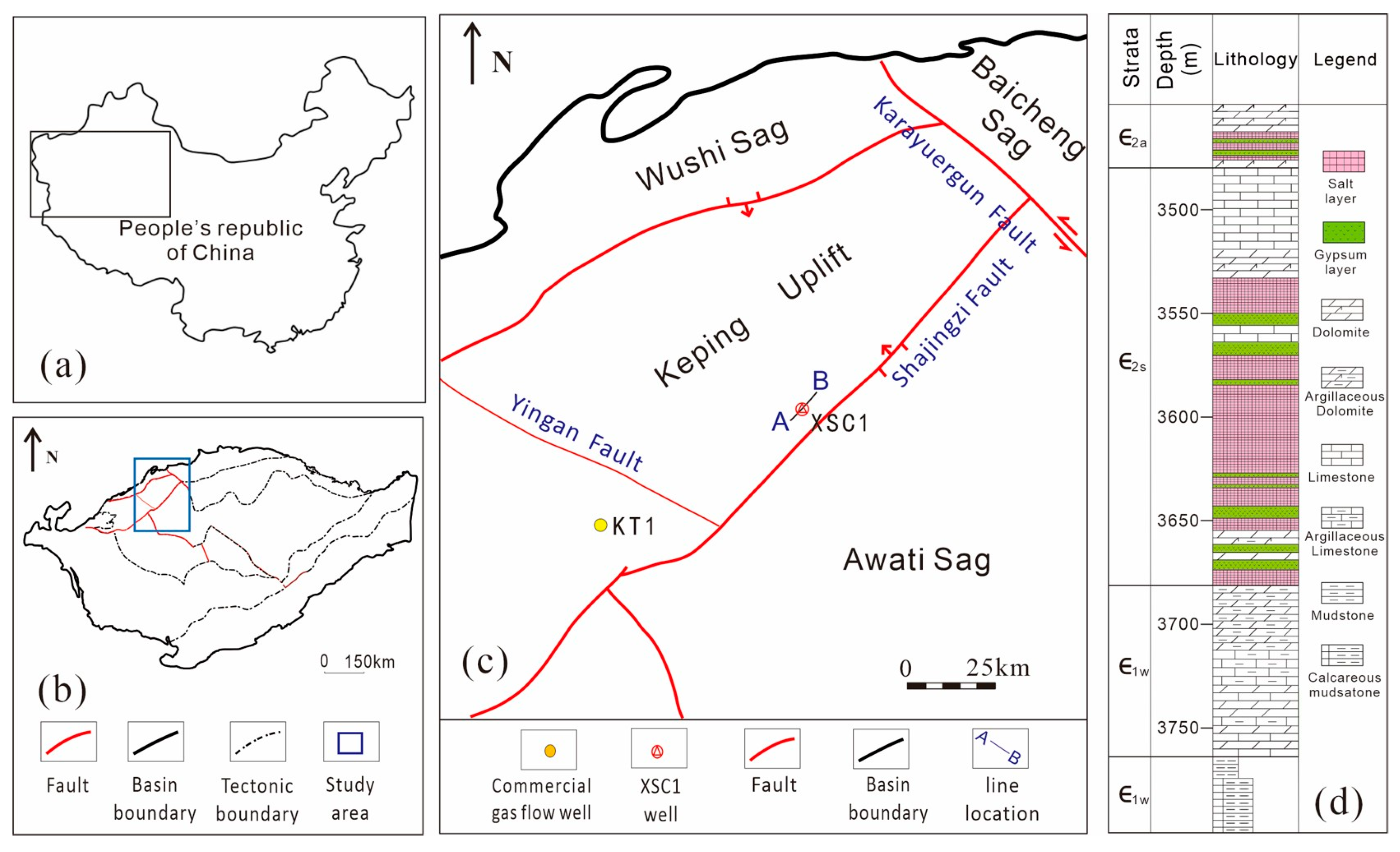
Figure 2.
(a) Crossplot of density versus P-wave velocity for major lithologies of the Lower–Middle Cambrian in the northwestern Tarim Basin, and (b) P-impedance distributions and overlap coefficient matrix.
Figure 2.
(a) Crossplot of density versus P-wave velocity for major lithologies of the Lower–Middle Cambrian in the northwestern Tarim Basin, and (b) P-impedance distributions and overlap coefficient matrix.
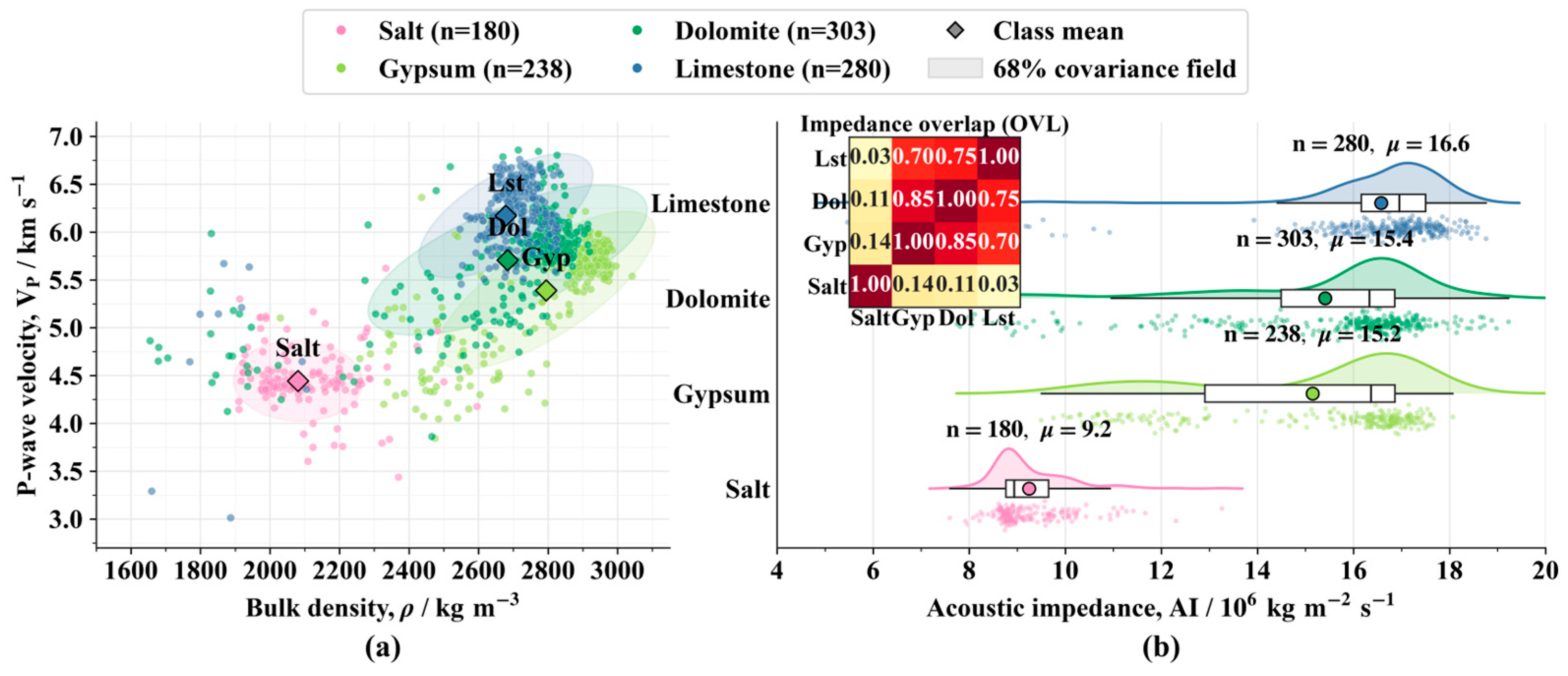
Figure 3.
Flowchart of the multi-parameter coupling method integrating seismic, drilling and logging data for comprehensive prediction of gypsum-salt sequences.
Figure 3.
Flowchart of the multi-parameter coupling method integrating seismic, drilling and logging data for comprehensive prediction of gypsum-salt sequences.
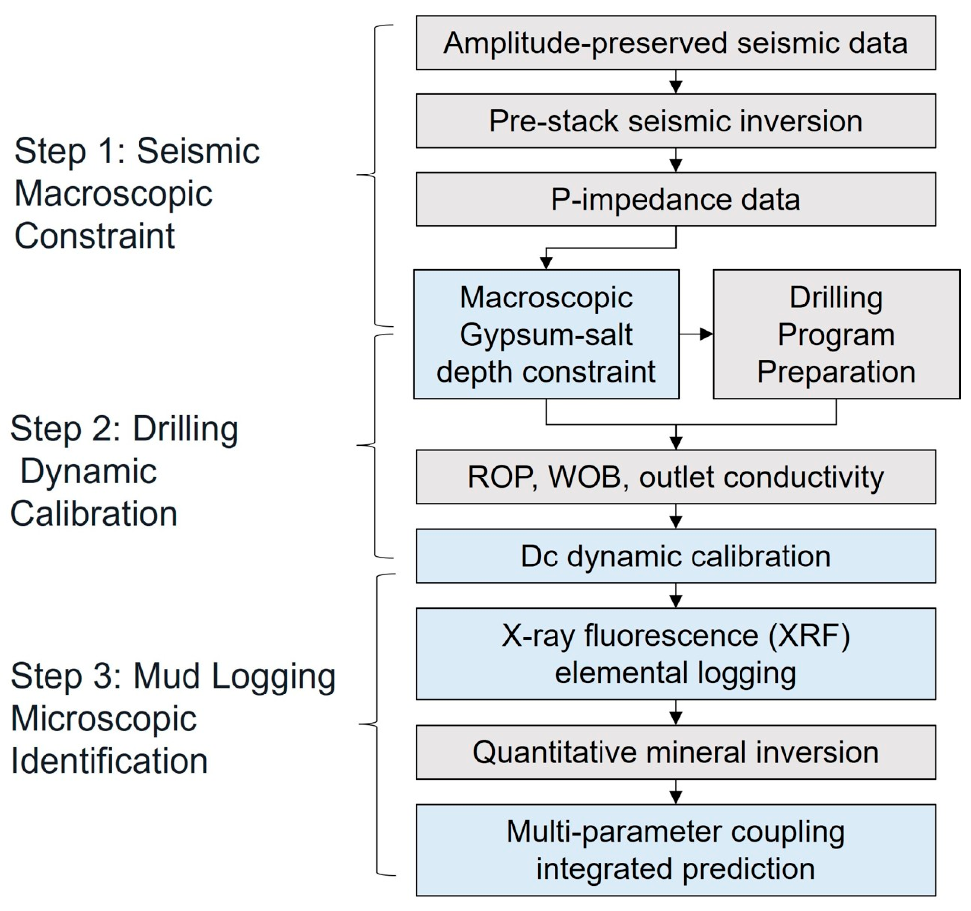
Figure 4.
Comparison of (a) full-stack seismic section and (b) pre-stack inverted P-impedance section across well XSC1.
Figure 4.
Comparison of (a) full-stack seismic section and (b) pre-stack inverted P-impedance section across well XSC1.
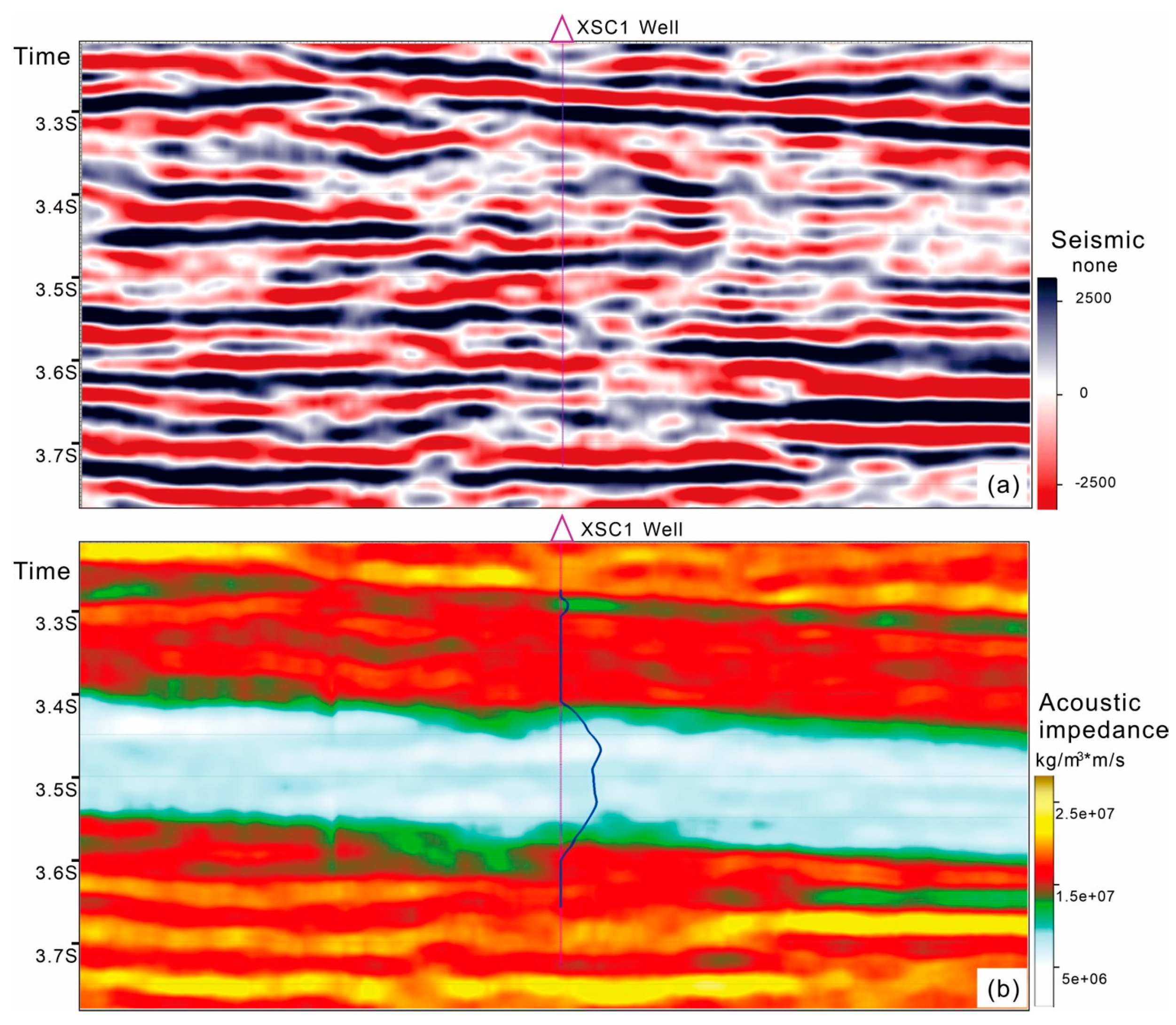
Figure 5.
Comparison of (a) outlet conductivity, (b) rate of penetration (ROP), (c) weight on bit (WOB), (d) synthetic drilling parameter change rate, and (e) P-impedance inversion prediction of the gypsum-salt interval along the seismic trace at well XSC1.
Figure 5.
Comparison of (a) outlet conductivity, (b) rate of penetration (ROP), (c) weight on bit (WOB), (d) synthetic drilling parameter change rate, and (e) P-impedance inversion prediction of the gypsum-salt interval along the seismic trace at well XSC1.
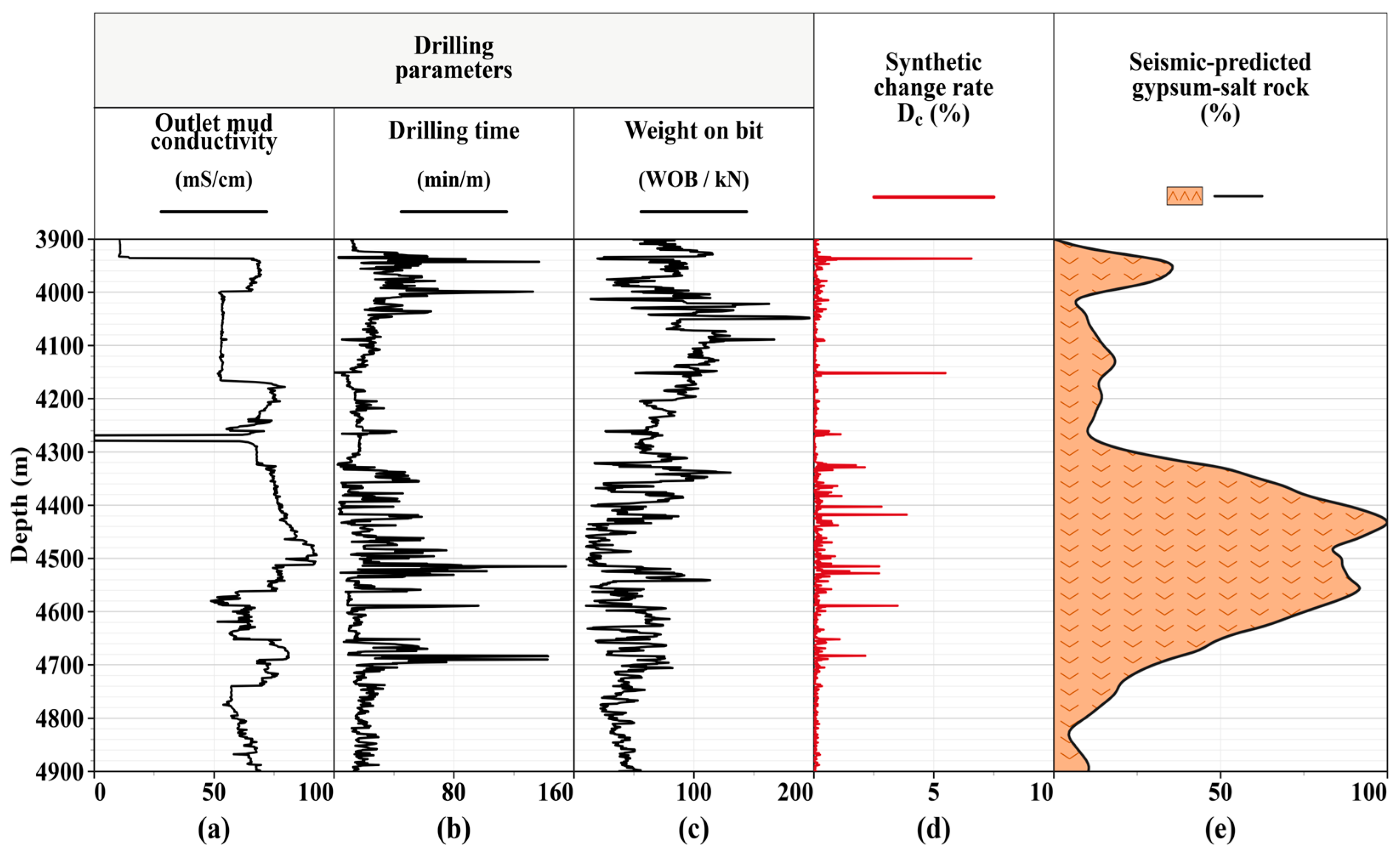
Figure 6.
Comparison of (a) drilling parameter change rate, (b) seismic inversion P-impedance, (c) X-ray fluorescence elemental logging data, and (d) multi-parameter integrated lithological column for well XSC1.
Figure 6.
Comparison of (a) drilling parameter change rate, (b) seismic inversion P-impedance, (c) X-ray fluorescence elemental logging data, and (d) multi-parameter integrated lithological column for well XSC1.
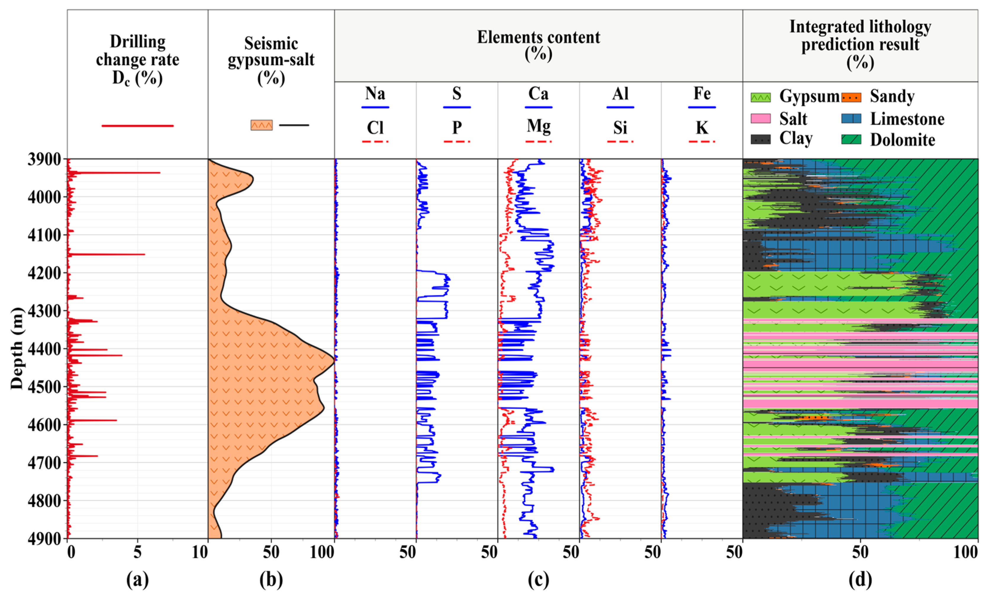
Figure 7.
Conventional seismic prediction of total gypsum-salt content (a), log-interpreted total gypsum-salt content (b), and their depth-domain comparison (c).
Figure 7.
Conventional seismic prediction of total gypsum-salt content (a), log-interpreted total gypsum-salt content (b), and their depth-domain comparison (c).
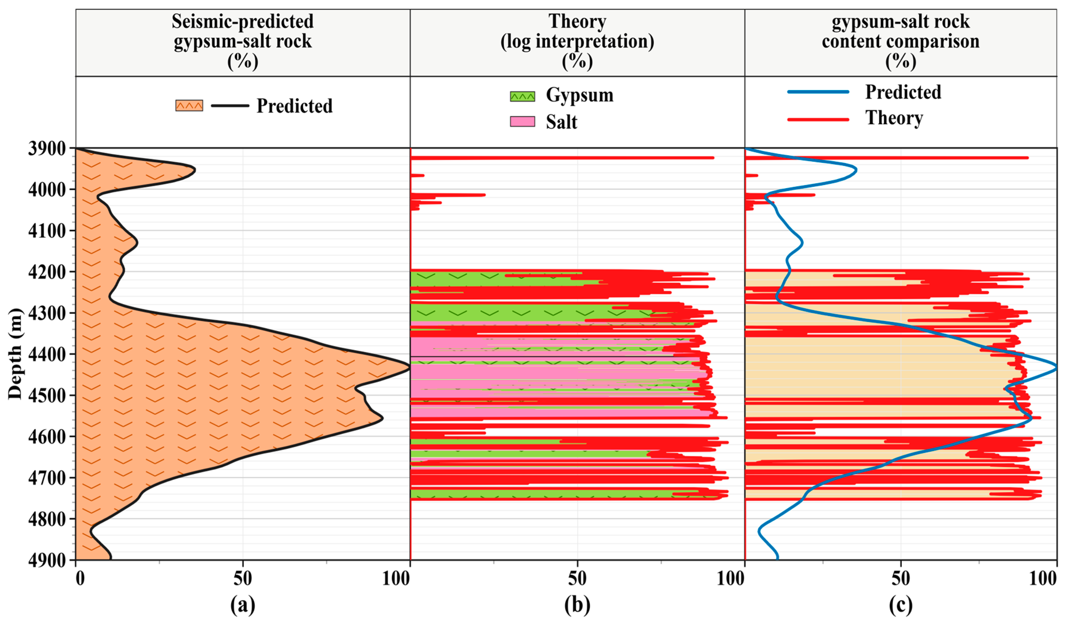
Figure 8.
Multi-parameter integrated lithological column (a), log-interpreted lithology (b), and comparisons of (c) total gypsum-salt content, (d) gypsum content, and (e) salt content.
Figure 8.
Multi-parameter integrated lithological column (a), log-interpreted lithology (b), and comparisons of (c) total gypsum-salt content, (d) gypsum content, and (e) salt content.
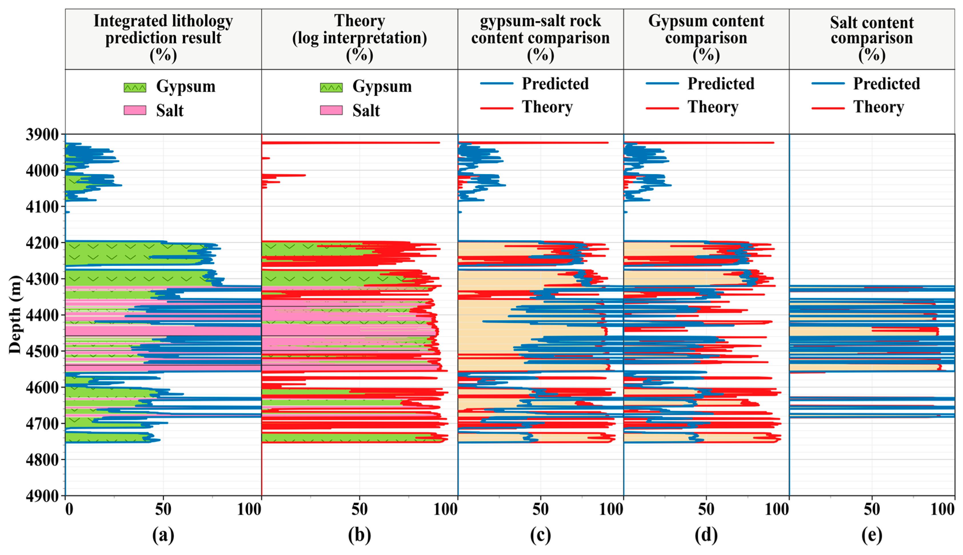
Figure 9.
Depth-domain distributions of (a) log-interpreted lithology and content, (b) conventional seismic prediction error of total gypsum-salt content, (c) integrated prediction error of total gypsum-salt content, (d) integrated prediction error of gypsum content, and (e) integrated prediction error of salt content.
Figure 9.
Depth-domain distributions of (a) log-interpreted lithology and content, (b) conventional seismic prediction error of total gypsum-salt content, (c) integrated prediction error of total gypsum-salt content, (d) integrated prediction error of gypsum content, and (e) integrated prediction error of salt content.
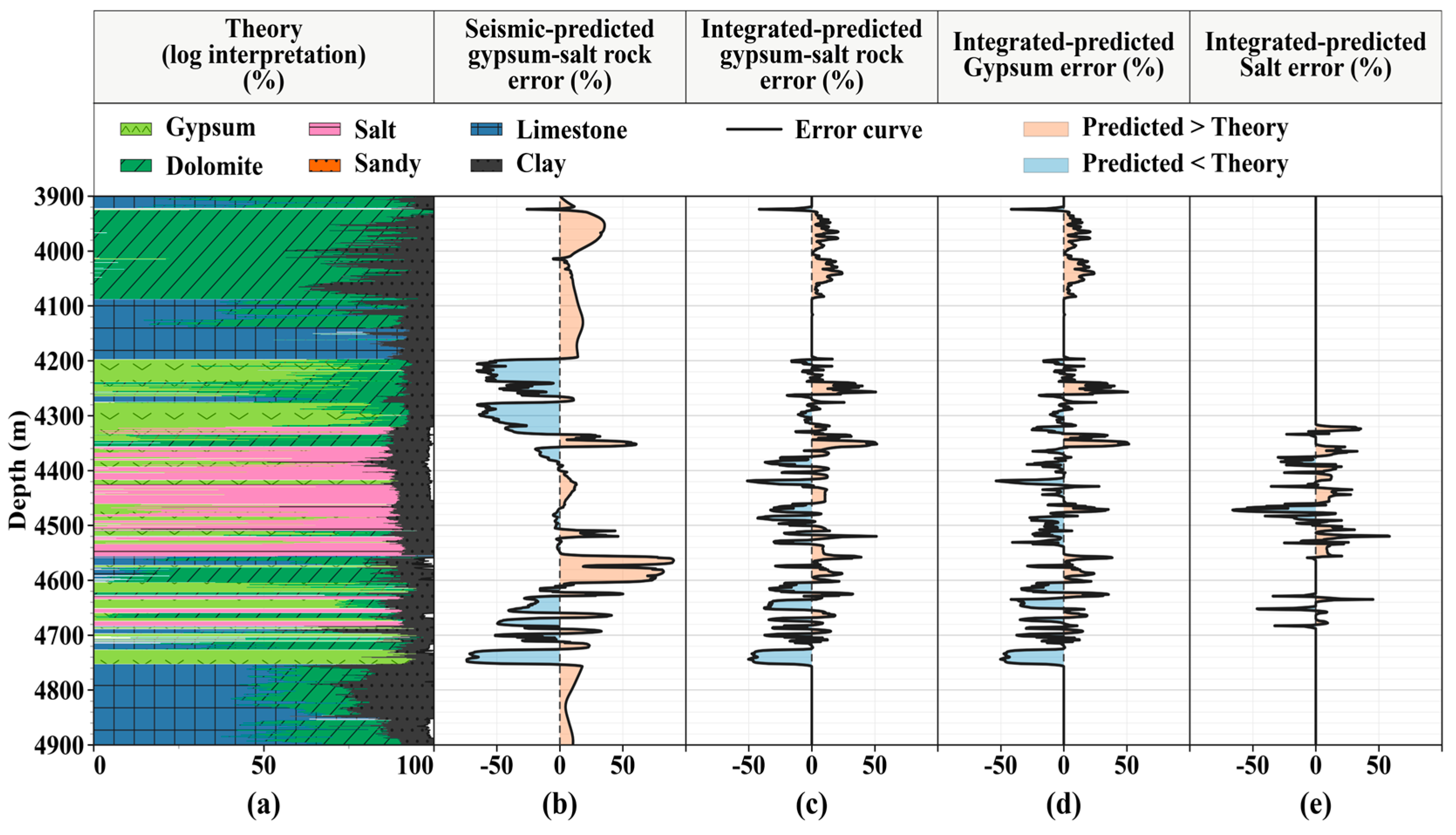
Figure 10.
Binary confusion matrices at a 1 % content threshold for (a) conventional seismic prediction of gypsum-salt rocks, (b) integrated prediction of gypsum, (c) integrated prediction of salt, and (d) integrated prediction of gypsum-salt rocks.
Figure 10.
Binary confusion matrices at a 1 % content threshold for (a) conventional seismic prediction of gypsum-salt rocks, (b) integrated prediction of gypsum, (c) integrated prediction of salt, and (d) integrated prediction of gypsum-salt rocks.
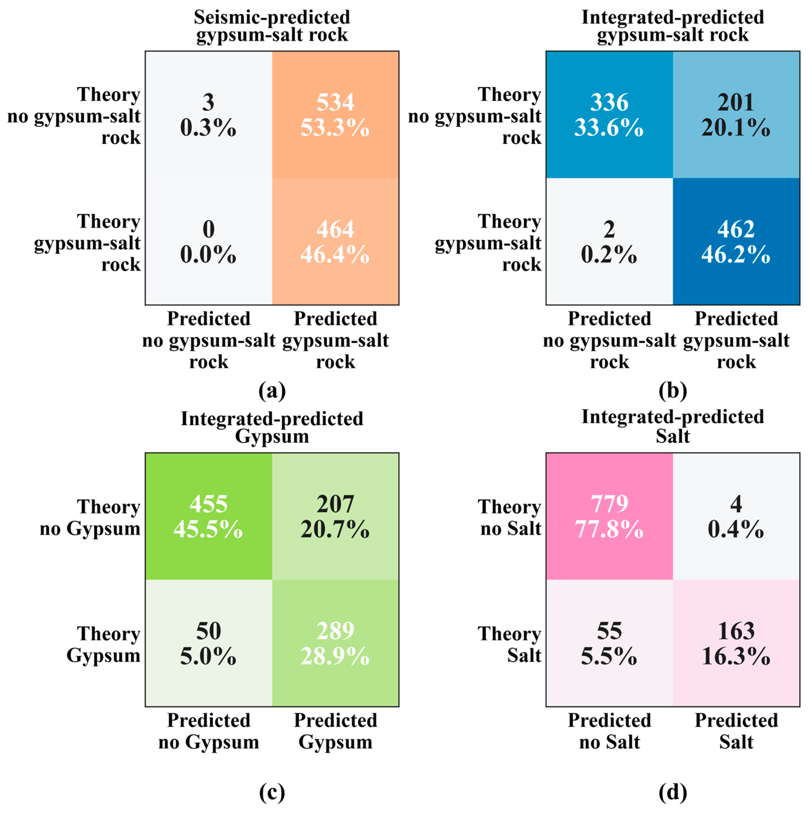

Table 1.
Major element contents of common minerals in a carbonate rock section.
| Mineral | Formula | Main Element Content | Remarks |
| Clay minerals | Illite: KAl3Si3O10(OH)2 Kaolinite: Al4Si4O10(OH)8 Montmorillonite: (Na,Ca)0.33(Al,Mg)2Si4O10(OH)2 Chlorite: (Mg,Fe)5Al(Si,Al)4O10(OH)8 |
Si=Sistd, Al=Alstd, Fe=Festd, Mg=Mgstd |
Obtained by analysis |
| Dolomite | CaMg[CO3]2 | Ca=21.7%, Mg=13.0% | Calculated from chemical formula |
| Pyrite | FeS2 | Fe=46.7%, S=53.3% | |
| Anhydrite | CaSO4 | Ca=29.4%, S=23.5% | |
| Calcite | CaCO3 | Ca=40.0% | |
| Quartz | SiO2 | Si=47.0% | |
| Halite | NaCl | Na=38.3%, Cl=61.7% |
Table 2.
Error statistics for seismic and integrated gypsum-salt prediction results.
| Metric | Seismic Predicted Gypsum-Salt | Integrated Gypsum-Salt | Integrated Gypsum | Integrated Salt |
| Bias (%) | 2.45 | 0.31 | 0.42 | 0.73 |
| MAE (%) | 24.56 | 13.73 | 11.95 | 5.58 |
| RMSE (%) | 33.63 | 21.55 | 20.71 | 16.13 |
| Median AE (%) | 14.74 | 9.26 | 2.81 | 0.00 |
| Error SD (%) | 33.56 | 21.56 | 20.71 | 16.12 |
| MAE reduction (%) | - | 44.1 | - | - |
| Improved depths (%) | - | 70.2 | - | - |
Table 3.
Classification metrics for seismic and integrated prediction results at a 1% content threshold.
Table 3.
Classification metrics for seismic and integrated prediction results at a 1% content threshold.
| Metric | Seismic Predicted Gypsum-Salt | Integrated Gypsum-Salt | Integrated Gypsum | Integrated Salt |
| Threshold | 1% | 1% | 1% | 1% |
| Accuracy | 0.47 | 0.80 | 0.74 | 0.94 |
| Precision | 0.46 | 0.70 | 0.58 | 0.98 |
| Recall | 1.00 | 1.00 | 0.85 | 0.75 |
| F1 | 0.63 | 0.82 | 0.69 | 0.85 |
Disclaimer/Publisher’s Note: The statements, opinions and data contained in all publications are solely those of the individual author(s) and contributor(s) and not of MDPI and/or the editor(s). MDPI and/or the editor(s) disclaim responsibility for any injury to people or property resulting from any ideas, methods, instructions or products referred to in the content. |
© 2026 by the authors. Licensee MDPI, Basel, Switzerland. This article is an open access article distributed under the terms and conditions of the Creative Commons Attribution (CC BY) license (http://creativecommons.org/licenses/by/4.0/).
Copyright: This open access article is published under a Creative Commons CC BY 4.0 license, which permit the free download, distribution, and reuse, provided that the author and preprint are cited in any reuse.


