Preprint
Review

This version is not peer-reviewed.

Challenges in Oxygen Evolution on the Nickel-Iron Catalysis: A Critical Review

A peer-reviewed version of this preprint was published in:
Metals 2026, 16(7), 745. https://doi.org/10.3390/met16070745

Submitted:

26 June 2026

Posted:

30 June 2026

You are already at the latest version

Abstract

Green hydrogen production via water electrolysis is a cornerstone of the sustainable energy transition. However, the oxygen evolution reaction (OER) remains the kinetic bottleneck, limiting overall efficiency. Nickel-iron (NiFe) based catalysts are among the most promising non precious materials for the OER in alkaline media, offering high activity and low cost. Nevertheless, their practical application at industrially relevant current densities (>100 mA cm–2) is hindered by several challenges: structural degradation, uncontrolled surface reconstruction, metal dissolution (corrosion), particularly Fe leaching, and the ambiguous role of the fundamental mechanisms. This review critically discusses the current understanding of these degradation pathways, the influence of preparation methods, the interplay between Ni and Fe redox chemistry, and strategies for enhancing long-term stability. Future directions for designing durable NiFe OER electrocatalysts are also outlined. The paper also considered a strategy for investigating new catalysts using electrochemical and non-electrochemical techniques, devoted to young scientists interested in this field. In the Outlook and Perspective, the key drawback is present and the possible strategy for improvement is discussed.
Keywords: 
;  ;  ;  

1. Introduction

Global primary energy consumption is projected to rise by more than 25% by the year 2040 [1]. Unfortunately, fossil fuels continue to supply the majority of this energy. According to the World Meteorological Organization (WMO), total carbon dioxide equivalent (CO₂,eq) emissions reached approximately 42 gigatonnes (Gt) in 2024 [2]. This contains 37.4 Gt from fossil fuel burning, with the rest mainly originating from land-use vicissitudes such as deforesting, contributing to 2.0% increase over the previous record in 2023. These tendencies emphasize the pressing need to transition in the direction of scalable and environmentally friendly renewable energy transitions. In this context, green hydrogen (H2) has gained attention as a favorable choice for considerably lowering the carbon footprint of the global energy systems. Due to hydrogen high gravimetric energy density (hydrogen boasts the highest gravimetric energy density of all chemical fuels, delivering about 120 MJ kg–1, approximately 33.6 kWh kg–1, that is roughly 2.5 to 3 times greater than traditional fossil fuels like gasoline), wide availability, diverse applications, and near-zero carbon emissions potential, hydrogen is poised to play a key role in advancing a sustainable energy future [3]. However, current hydrogen manufacture remains heavily reliant on methods such as coal gasification and steam reforming of natural gas processes that generate considerable CO2 emissions [4]. For instance, steam methane reforming proceeds via the following reaction [5]:
CH4 + H2O = 3H2 + CO
and followed by the water-gas shift reaction:
CO + H2O = H2 + CO2
In that process, gray hydrogen is obtained, or if CO2 is separated and stored, for example, underground via a very expensive route, blue hydrogen is obtained. A more feasible alternative is green hydrogen production by means of water electrolysis, where water is separated into hydrogen and oxygen using electricity sourced from renewables, mainly wind, solar, and hydroelectric power. Several technologies of water electrolysis exist that are in operation or under development, including the following: alkaline water electrolysis (AWE); proton exchange membrane electrolysis (PEME); solid oxide electrolysis cells (SOEC), and anion exchange membrane electrolysis (AEME) [6]. Each of these technological procedures has different industrial, productivity, and price characteristics. AWE is well established as a mature technology, the most conventional and widely adopted in industry. It sustains current attractiveness because of its low cost related to the other electrolysis technologies [7]. Green hydrogen produced through water electrolysis using renewable sources is a mainstay of low-carbon energy systems. It offers decarbonization of difficult-to-electrify sectors such as steel and cement, mixing with natural or biogas, ammonia and fertilizers, allows for long-duration energy storage, and provides seasonal and grid-balancing flexibility for large perceptions of variable renewables [8,9,10,11]. In addition, hydrogen-based internal combustion engines and hydrogen fuel cells are promising alternatives for transportation.

2. Fundamentals of OER and Water Electrolysis

Because it can be produced with almost near-zero CO2 lifecycle, when produced with renewables, green hydrogen is an important enabler of climate neutrality and decarbonized industrial value chains. Among different types of water electrolyzers [12], even old technology, alkaline electrolyzers are still dominant, due to the ease of maintenance, usage of inexpensive catalysts, low working temperatures, etc. [7]. The straightforward path to green hydrogen is electrochemical water splitting:
2H2O = O2 + 2H2
but the oxygen evolution reaction (OER) in alkaline solution is the kinetic bottleneck. Usually, it involves formation of the strongly bound intermediates (like *OH, *O, *OOH), and four electron transfers are required:
4OH = 2H2O + O2 + 4e
thus, it is slow and energy demanding [13].
Partial reaction for hydrogen (HER) and oxygen evolution (OER) reactions in alkaline solutions are:
Preprints 220444 i001
and
Preprints 220444 i002
The theoretical decomposition voltage, U0, of water is 1.23 V, due to different overpotentials, η, resistance of the electrolyte and diaphragm, operating voltages are in the range of 1.7 up to 3 V [14]. Theoretically, for 1 kg of H2, it is necessary to use ~33.6 kWh of electric energy. In the real systems, specific energy consumption, ws, per kg of H2 is much higher, in the range from 50 kWh to 70 kWh [14]. The specific energy consumption is given by:
Preprints 220444 i003
where under the same current, time, and mass of hydrogen, only the voltage can decrease specific energy consumption. Hereafter, lowering the electrolysis voltage at constant current, time, and mass of hydrogen, by finding good electrocatalysts that will decrease overpotentials, plays a crucial role.
To understand the catalytic role of the catalysis, it is necessary to see the structure of the electrolysis voltage:
Preprints 220444 i004
where U0 is the difference of anodic and cathodic reversible potentials defined as:
Preprints 220444 i005
or taking into account that standard reversible potentials, Erθ for oxygen is 1.23 V, and for hydrogen 0 V, neglecting the partial pressure, it is obtained:
Preprints 220444 i006
or after rearmament:
Preprints 220444 i007
Therefore, at a given temperature and concentration of the OH, the reaction rate cannot be significantly improved with U0. But the overpotentials are directly connected with current density and catalytic properties of the electrode materials. The current density depends on overpotentials, as given
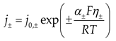
Preprints 220444 i008
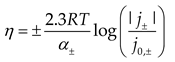
where, “+” is valid for anodic, and “–“ for cathodic current density, where η = EEr, j0 exchange current density, which contains exponential terms of Er, and most importantly Gibbs energy ΔG# of activation, that is crucial for increase rate of the reaction, and α is transfer coefficient that is dependent of reaction mechanisms and can have values of 0.5, 1, 1.5, 2. From Equation (12), the Tafel equations can be derived:
Preprints 220444 i009
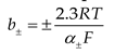
From the pre-exponential terms, the Tafel slope can be derived:
Preprints 220444 i010
Taking into account the transfer coefficient, Tafel slopes can be 120, 60, 40, and 30 mV dec–1. The importance of the Tafel slope, which is connected with the mechanism can be seen in Figure 1a,b. Figure 1a shows the structure of the alkaline electrolyte electrolysis potentials, for two different Tafel slopes (for simplicity, j0 and b, for OER and HER, are taken with the same values). As can be seen, the voltage of the electrolysis at the constant current density is ~0.2 V lower for the Tafel slope of 60 mV dec–1 than for 120 mV dec–1. This is mainly a consequence of better catalytic properties of the catalysts. According to Equation (8), Figure 1 shows electrolysis voltages for two different Tafel slopes, and it is obvious that with lower Tafel slopes, water splitting is more energetically favorable, which directly decreases specific energy consumption and the price of hydrogen.
Considering OER, the four-electron transfer is highly demanding, which implies a very complex mechanism [15]. In the oxygen evolution reaction (OER), the classical Adsorbate Evolution Mechanism (AEM) and the Lattice Oxygen Mechanism (LOM) differ in both the reaction pathway and the origin of the evolved oxygen [16,17,18]. In AEM, the catalyst serves mainly as a surface for stepwise oxidation of adsorbed intermediates (*OH, *O, *OOH), and the produced O2 comes entirely from water. In contrast, LOM involves direct participation of oxygen atoms from the catalyst lattice, an oxygen atom from the solid can leave the structure and combine into O2, creating an oxygen vacancy that is later refilled by oxygen from water. Because of this, LOM can bypass some of the energetic limitations typical of AEM, and potentially enhance activity, although it may also compromise structural stability due to continuous lattice involvement. The mechanism of AEM and LOM can be presented with the following sequences:
AEM
S + OH⁻ → S–OHads + e
S–OHads + OH⁻ → S–O* + H2O + e
S–O* + OH⁻ → S–OOH* + H2O + e
S–OOH* + OH⁻ → S + O₂ + H2O + e
LOM
M(II)–OlatH + OH⁻ → M(III)–Olat + H2O + e
M(III)–Olat + OH⁻ → M(IV)–Olat–O + H2O + e
2[M(IV)–Olat-O] → M(II)–VO + O₂(g)]
2M(II)–VO + OH⁻ → 2M(II)–OlatH + 2e
For the AEM is characteristics that in the reactions only surface active centers, S, is involved, and metals do not change valence states, while for LOM, the lattice metal-oxide, M(II)–OlatH, is involved, where metals (Ni, Fe), change their valence state producing vacancies, M(II)–VO, and if the vacancies is not effectively converted to lattice, degradation of catalyst can occur. The rate-determining step (RDS) depends on the catalyst and cannot be simply determined. Even though the LOM is considered a favorable path, on some occasions, the oxygen lattice from the subsurface could be involved, which could produce materials degradation (corrosion).
Among AEM and LOM, recently, are presented the oxide pathway mechanism (OPM) and the Mars-van Krevelen mechanism that proposed further alternative directions for O–O bond creation. OPM contains direct coupling of two adjacent metal-oxygen positions without lattice oxygen removal, but it involves exact metal-metal distances on the surface, which are problematic to reach and sustain under working conditions [19,20,21]. The Mars-van Krevelen mechanism, thoroughly connected to LOM, explicitly includes the exchange of lattice oxygen with the electrolyte; its main restriction is that the constant extraction of lattice oxygen can lead to catalyst dissolution if oxygen vacancies are not adequately refilled. Even though the direct O–O coupling for oxygen evolution is well known; the study of the OPM for OER is still in its recent stage. Compared to AEM and LOM, there are additional unknown factors that may affect the OPM and Mars-van Krevelen pathway, and even the identification of the OPM remains an inspiring task [19]. Understanding the conditions under which each mechanism operates, and their particular limitations, is crucial for designing stable and active OER electrocatalysts [22].
After all, it is not surprising that Fabbri and Schmidt 2018 wrote: Even the splitting of water was known since the 19th century, after Paets van Troostwijk and Deiman, as well as Nicholson and Carlisle, discovered that (static) electricity can split the water into hydrogen and oxygen, the oxygen evolution reaction is still an enigma [23].

3. The Catalyst Synthesis Methods and Their Influence on the Activity

The noble metals and their oxides (like IrO2, RuO2, Pt) are considered as the well-known catalysts for oxygen evolution reaction, but are limited for scale-up by their price and shortage for scale-up. But, due to the difficulties with the adsorption of the oxygen intermediates in basic solutions, those catalysts show modest activities. For example, Jang et al. [24] for IrO2 in 1 M KOH reported overpotential, η100, of 570 mV at a current density of 100 mA cm–2. Tachikawa et al. [25] for sputter-deposited flat IrO2 thin films, reported in 1 M KOH at 10 mA cm–2, overpotential, η10, of ~370 mV, while Palani et al. [26] investigated Pt and RuO2 in 1 M KOH at 10 mA cm–2, achieved for Pt negligible activity at 2 V vs RHE and at η10 of 470 mV for RuO2. Chen et al. [27] among other catalysts investigated RuO2 in 1 M KOH, and at 25 mA cm–2 obtained overpotentials of 310 mV, but during 8 h, current densities decreased from 12 mA cm–2 to 5 mA cm–2. Therefore, due to modest activity and high price, noble metals and their oxides are not suitable for alkaline water electrolysis as an anode catalyst. On the contrary, iron group metals, Fe, Ni, Co, are of intense research due to corrosion stability in alkaline electrolyte, and relatively low price. However, as shown by Si et al. [28], overpotentials at 10 mA cm–2, for the metals covered with oxy-hydroxide, were obtained by cycling of the pure metals in the oxygen evolution region. For NiOOH, the overpotential is 441 mV, for CoOOH 454 mV, while for FeOOH, up to 1.7 V vs RHE, and did not show any significant activity.
Afterward, the innovative work of Corrigan [29] revealed almost four decades ago that a thin-film nickel oxide electrode showed insignificant OER until overpotentials in excess of 400 mV are applied, but that absorption of trace iron contaminations (1 to 10 ppm) effectively lowered the overpotential and improved activity. Iron is precipitated into the NiOOH film when ferric nitrate is added to the nickel nitrate solution used for electrodeposition. Higher concentrations of iron precipitated into a complex iron/nickel hydrous oxide effectively catalyzed the OER by decreasing the Tafel slope from about 70 mV dec–1 with no iron existing to about 25 mV dec–1 with 10–50% of the iron. This result was later confirmed and extended by Trotochaud et al. [30], who methodically studied electrodeposited Ni(OH)2 and NiOOH films in purified electrolyte. They showed unambiguously that Fe-free NiOOH requisite >400 mV to reach 10 mA cm–2, although careless absorption of Fe sunk η10 by ~200 mV, emphasizing the significance of Fe in main activity. These low-activity starting points persist significant control facts, prompting the scientists that Ni alone cannot explanation for the outstanding enactment in the activity, so often reported in the literature. Nickel–iron (oxy)hydroxides have become the standard benchmark for a non-noble OER electrocatalyst in alkaline electrolyte, but their development has been anything but straightforward.
The state-of-the-art, earth-abundant electrocatalysts for the OER in alkaline media, for now, are nickel-iron layered double hydroxides (LDH). Initially in 2013. Gong et al. [31] described ultrathin NiFe LDH nanoplates on carbon nanotubes with an overpotential of ~210 mV at 10 mA cm–2, establishing their potential for OER. Additionally, dissimilar synthetic methods are developed toward activity improvement, morphology control, and stability. Due to different preparation methods and synthesis conditions, reported overpotentials for current density of 10 mA cm–2 vary between 130 mV and 350 mV [32]. The most broadly used approaches are co-precipitation, hydrothermal synthesis, electrodeposition, and moderately less used urea-assisted hydrolysis, microwave-assisted synthesis, and the mechanochemical processes.
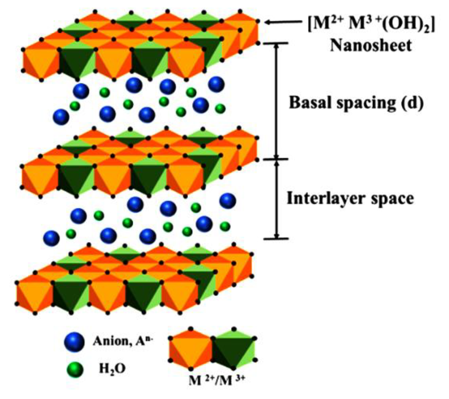
The structure of the LDH catalyst is highly intricate, as illustrated in Figure 2 [33]. Its general formula is [M2+1-xM3+x(OH)₂]x+[Anx/n]x–·mH₂O, where M2+ and M3+ represent divalent and trivalent metal ions, respectively. An– represents negatively charged interlayer guest anions (e.g., CO₃²⁻, NO₃⁻, Cl⁻, SO₄²⁻), and the molar ratio of M3+ to (M2+ + M3+) is represented by x, which typically ranges from 0.2 to 0.33. The LDH structure is derived from brucite-like Mg(OH)₂ layers, which consist of infinite sheets of edge-sharing M(OH)₆ octahedra. In these octahedral, metal cations occupy the center, surrounded by six OH⁻ ions at the corners. The host layer acquires a positive charge due to the coexistence of divalent and trivalent metal cations, and this charge is balanced by anions along with water molecules located in the interlayer region. The basal spacing (d) in LDH materials refers to the distance from the center of one host layer to the center of the adjacent layer; thus, it equals the sum of the brucite-like layer thickness and the interlayer space.
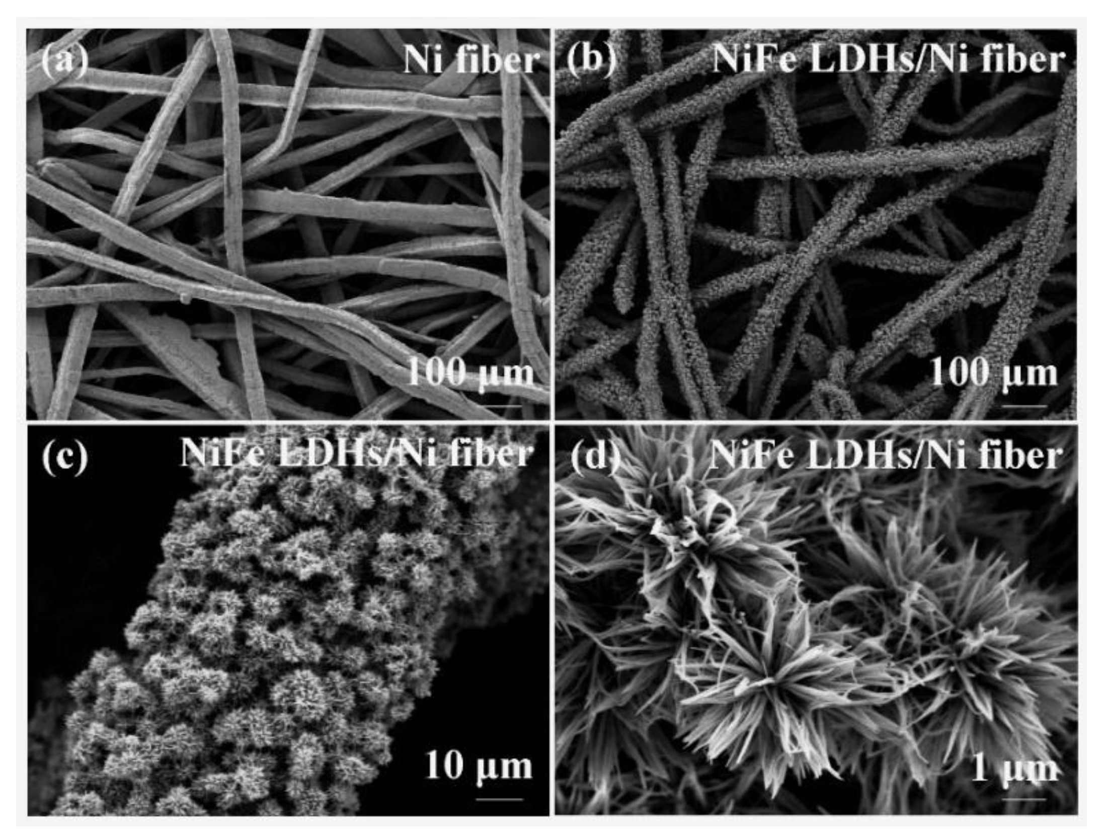
As the structure is very complex, the morphology significantly varies, like: hexagonal platelets, nanosheets, nanolayers, microspheres, flakes, to nanoflower as can be seen in Figure 3 [34].
Co-precipitation is a frank method relating nickel and iron salts' precipitation under alkaline conditions, which permits the control of the composition but produces powders that usually exhibit low conductivity and rather modest performance at high currents (for example, ~360 mV at 10 mA cm–2) [35]. Hydrothermal synthesis can grow NiFe LDH nanosheets straight onto a conductive substrate for an enhancement in electrical contact, alongside robustness at high currents. Li et al. [36]reported the hydrothermally grown NiFe LDH onto nickel foam (NF) that reached 175 mV at 10 mA cm–2 with constant operation at 500 mA cm–2 for 50 h. Liu et al. [37] investigated a simple one-step hydrothermal method, and at a current density of 100 mA cm−2 achieved an overpotential of 387 mV, and acceptable stability after constant operation of 28 h, at 1.63 V vs RHE (η = 400 mV) at a current density of ~25 mA cm–2. Hydrothermal growth of NiFe layered-double hydroxide (LDH) nanosheets on nickel foam and Raney Ni precursor is found to form vertically-aligned electrodes with high surface area (>150 m2·g–1) and low overpotentials, ≈124 to 300 mV at 10 mA·cm–2; ~320 to 400 mV at 100 mA·cm⁻² in 1 M KOH [38]. Guoqi et al. [39] investigated NiFe double-layer hydroxide synthesized by the hydrothermal method mixed with terephthalic acid (TPA) in 1 M KOH that displays good performance at the current density of 2 mA cm−2 at an overpotential of 270 mV, with the Tafel slope of 40 mV dec−1. At higher current densities, 10 mA cm−2 and 100 mA cm−2, overpotentials were 320 mV and 570 mV. Thermal decomposition (calcination) of composite Ni/Fe is a scalable route for NiFe oxides; activity is then sensitive to calcination conditions, time, after-treatment, and Ni:Fe composition, with overpotentials at 100 mA·cm–2 being ~280–300 mV depending on optimization [40].
Electrodeposition is one of the most widely used methods for the synthesis of the NiFe DLH. Quiroz et al. [41] electrodeposited NiFe LDH with different Ni:Fe fractions of 15:1, showing the best catalytic activity for OER with the low Tafel slope of 38 mV dec-1 and the overpotentials of 206 mV and 244 mV at 30 mA cm–2 and 100 mA cm–2 in 1 M NaOH. At the current density of 400 mA cm–2, a constant overpotential of ~300 mV is accomplished, throughout 25 h. Electrodeposition of the NiFe/NF electrode shows high catalytic activity towards OER in alkaline solutions that only needs an overpotential of 200 mV to initiate the reaction, and overpotentials for current densities of 50 and 500 mA cm−2 reached 250 and 620 mV, respectively. [24]. Swierk et al. [43] present a comprehensive manuscript about the OER activity of the electrodeposited NiFe LDH in 1 M KOH, varying Fe content from 0 to 100%. At overpotentials of 400 mV, they obtained current densities of: 0% Fe 2 mA cm–2, 10% Fe 15 mA cm–2, 24 % Fe 35 mA cm–2, 34% Fe 40 mA cm–2, 75% Fe 10 mA cm–2, and 100% Fe 5 mA cm–2. At 10 mA cm–2, determined overpotentials are: 0% Fe 540 mV, 10% Fe 375 mV, 24 % Fe 345 mV, 34% Fe 330 mV, 75% Fe 400 mV, and 100% Fe 440 mV. The Tafel slope for electrodes is in the range from 60 to 65 mV dec–1, except for pure nickel with 105 mV dec–1.
In urea-assisted hydrolysis, the growth of NiFe LDH is controlled by the sluggish decomposition of urea. Wu et al. investigated urea-assisted NiFe LDH, and showed that interlayer anions and morphology of NiFe LDH are tunable via urea hydrolysis, but the authors did not investigate OER [44]. Zuber et al. [45] investigated urea-assisted synthesis of NiFe LDH from nitrate, sulfate, and mixed salt. Applying the current density of 10 mA cm–2, overpotentials for nitrate are 425 mV, for sulfate 460 mV, and for mixed precursor salt 346 mV. Nevertheless, the permanence of the electrodes during the stability test was very low.
Microwave-assisted synthesis of NiFe produces thin nanosheets in a very short period of time, accordingly permitting the high surface area with low overpotentials, such as 250 mV at 10 mA cm–2 as reported by Hou et al. [46]. Iwasaki et al. [47] investigated mechanochemical methods syntheses, but such methods produce low crystallinity of the product. Molina-Muriel et al. [48] using a mechanochemical process, investigate the obtained product for OER, and at a current density of 10 mA·cm–2 achieved overpotentials of 220 mV and a Tafel slope of ~100 mV·dec–1, demonstrating admirable OER kinetics. In addition, the catalyst verified robust permanence, keeping a potential of about 1.55 V (η = 520 mV) during 35 h at a current density of 100 mA·cm–‍2 and 1.75 V (η = 520 mV) at 1 A·cm–2.
Beyond structural factors, the type and concentration of the electrolyte also play a critically important role. Del Rosario et al. [49] explore how hydroxide cations affect the OER. They demonstrate that the activity of IrOx and NiCo2O3 increases in the order Li+< Na+< Cs+< K+ in 1 M MOH solutions. This trend arises mainly from differences in the interaction strengths of specifically adsorbed OHad intermediates and non-specifically adsorbed alkali metal cations (AM+ad) inside the electric double layer. Comparable results are reported by Garcia et al. [50] aimed at nickel oxyhydroxide (NiOOH), with the cation effect following Cs+ > Na+ > K+ > Li+, confirming an intrinsic influence of the cation on OER activity. In 1 M KOH, K+ ions favor better ionic movement and more uniform interfacial charge separation, which lowers overpotentials compared to 1 M NaOH, where strongly hydrated Na+ ions hinder ion movement and block access to the active centers [51]. Park et al. [52] investigate the effect of NaOH concentration on IrO2 anodes' activity. Applying a constant overpotential of 420 mV, and increasing NaOH concentrations from 0.01 to 0.02, 0.10, 0.50, and 1.0 M yields the current densities of 3, 5, 40, 50, and 80 mA cm–2, respectively. Increased NaOH concentration improves conductivity (reducing IR losses), which benefits kinetics and generally drops the overpotentials by about 200 mV under an applied current density of 100 mA cm–2 when comparing 1 M and 30% KOH [53]. Luo et al. [54] hydrothermally prepared a NiFe-LDH@Fe₂O₃@NF composite and observed a remarkable pH-dependent activity increase. At 1.50 V vs. RHE (η = 0.23 V), raising the pH from 13.30 to 14 boosts the current density from roughly 20 mA cm–2 to an impressive 250 mA cm–2.
The temperature dependency of NiFe-based OER catalysts' activity is examined by Li et al. [55], who find that higher temperatures enhance mixed ionic conductivity and accelerate OER kinetics. This finding highlights the need to characterize catalysts under realistic operating temperatures. On the other hand, Pascuzzi et al. [56] concluded that while NiFe (oxy)hydroxide is a highly active alkaline OER electrocatalyst, its stability is strongly tied to operating conditions. Under mild conditions (25 °C, 1 M KOH), only minor structural and compositional changes occur. However, at higher temperature (75 °C) and more realistic alkali concentration (5–10 M KOH), iron dissolution speeds up, lowering the Fe/Ni percentage, growing charge-transfer resistance, that speed up the OER activity.[7,22

4. Degradation Mechanisms and Stability Challenges

The stability of electrodes depends on several factors, including their morphology, adhesion to the substrate, degree of crystallinity, and electrical conductivity [57]. Therefore, both the synthesis method and the electrode design must be carefully tailored to ensure that the resulting materials maintain high activity and durability under operating conditions relevant to the oxygen evolution reaction (OER). The chosen synthesis pathway directly influences the structure and function of NiFe-based catalysts. Although NiFe catalysts perform excellently in laboratory settings, their application in industrial-scale alkaline electrolysis requires an optimal chemical composition, a large specific surface area, scalable production methods, and long-term durability to sustain low overpotentials at high current densities over extended operation [7,22]. Between parameters such as configuration, morphology, and actual surface area, the catalytic activity of NiFe oxides or oxyhydroxides in the OER is strongly affected by the oxidation states of nickel and iron. Specifically, the splitting of 3d orbitals into lower-energy t2g and higher-energy eg levels plays a key role. Ni2+ (t2g6, eg2) typically exhibits low activity, however, its oxidation to Ni3+ (t2g6, eg¹) results in an eg occupancy close to one, which optimizes metal-oxygen covalency and the energies of reaction intermediates adsorption, thereby enhancing catalytic behavior [30,58]. Further oxidation to Ni4+ (t₂g6, eg0) strengthens metal–oxygen bonds, which can increase activity but often reduces durability [58,59]. The iron, in the configuration Fe2+ (t2g4, eg2), leads to extra eg electrons that generally weaken activity due to stronger antibonding interactions. Nevertheless, mixed Fe2+/Fe3+ valence states can increase charge transport inside the crystal framework [29]. On the contrary, Fe3+ (t2g3, eg2), with its half-filled eg orbitals, enhances the activity of nickel sites by modifying the electronic configuration and increasing covalency [58,59]. Ultimately, the cooperative interaction between the Ni2+/Ni3+/Ni4+ and Fe2+/Fe3+ redox couples benefits to maintain an electronic configuration with eg occupancy close to one, a state consistently linked to the supreme OER activity, but in some cases decreases long-term operation due to preferential dissolutions.
The outstanding initial activity of NiFe-based oxygen evolution electrocatalysts is often compromised during prolonged operation at industrially relevant current densities (>100 mA cm–‍2). Understanding the fundamental degradation pathways is essential for designing durable anodes.
Under anodic polarization, the catalyst surface undergoes continuous restructuring. Amorphous or nanocrystalline NiFe oxides gradually transform into surface-layered (oxy)hydroxide phases, accompanied by oxidation of Ni2+ to Ni3+ (and occasionally Ni4+). This "electrochemical annealing" initially increases the number of active sites, but, over extended periods, leads to irreversible phase segregation. For instance, γ-Ni(Fe)OOH may convert to less active β-Ni(Fe)OOH, or the spinel structure may separate into NiO-rich and Fe2O3-rich domains [60,61]. Such transformations reduce the density of Ni–Fe pairs that are crucial for high OER activity. Nickel-iron layered double hydroxides (NiFe DHs), and electrodeposited NiFe films rank amongst the most favorable alkaline OER materials due to their earth-abundant, and extraordinary activity [62,63]. Nevertheless, neither material fully overcomes the stability challenges associated with long-term operation. For instance, NiFe-LDHs undergo structural degradation as their layered morphology collapses into inactive species, decreasing the number of active sites and diminishing performance [62,64]. These catalysts experience permanent surface phase transitions between γ-Ni(Fe)OOH and β-Ni(Fe)OOH, with conflicting reports on directionality. While such transitions lead to further activity loss, the β-Ni(Fe)OOH phase is widely considered to offer higher operational stability [62,65,66,67]. Additionally, the leaching of Ni and Fe in alkaline solutions contributes to degradation, especially at higher currents [63,64].
Similar problems affect electrodeposited NiFe catalysts. The electrodeposition route often produces films with poor mechanical integrity, making them prone to cracking or delamination in OER environments [68,69]. Additionally, repeated surface phase transformations convert the active NiFe (oxy)hydroxide phases into inactive oxides, thereby reducing catalytic efficacy [68,69]. Extended tests similarly reveal activity loss in various electrodeposited NiFe catalysts, showing their limited durability in alkaline media [68].
When the lattice oxygen mechanism (LOM) operates, oxygen atoms are removed from the solid lattice, creating oxygen vacancies (VO). The overall extraction can be described as:
M–O²⁻(lattice) → ½ O2(g) + M–VO + 2e
Under steady-state conditions, vacancies can be repaired by hydroxide ions from the electrolyte:
M–VO + 2OH⁻ → M–O²⁻(lattice) + H₂O + 2e
At low overpotentials, the healing rate balances vacancy generation. However, at high current densities, the extraction rate exceeds the healing capacity. Consequently, VO accumulates, leading to lattice distortion, loss of crystallinity, and eventually structural collapse [57]. Scanning electron microscopy (SEM) studies reveal that many NiFe catalysts prepared by electrodeposition or co-precipitation undergo severe morphological changes. The initially compact or nanosheet-like structure transforms into a highly porous, swollen layer that eventually detaches from the substrate. This phenomenon is attributed to deep hydration, vigorous oxygen bubble evolution, and internal stresses generated by oxygen vacancy formation [57].
The stability of NiFe catalysts is highly sensitive to the electrolyte environment. One of the most critical stability challenges is the selective dissolution of iron from NiFe catalysts. In alkaline electrolytes, Fe3+ (or Fe2+) is released into the solution, especially at elevated temperatures (e.g., 60–80 °C) [57] and in concentrated KOH (5–10 M) [59]. The dissolution of iron ferrateres to the incongruent dissolution of iron-rich LDHs into water or alkaline environments, which converts or oxidizes the liberated framework iron into iron(VI), as soluble FeO42– or iron(III) oxyhydroxides. A simplified dissolution reaction is [70,71]:
FeOOH + H2O → Fe(OH)3(aq) + e
Fe + 8OH → FeO42– + 4H2O + 6e
and includes the formation of FeOOH and Fe(OH)2 as reaction intermediates. It is also supposed that the reaction among FeOOH and Fe(OH)2 produces Fe3O4, which can act as a barrier against additional iron dissolution and avoid the formation of ferrate, but can decrease OER activity.
The loss (corrosion) of iron reduces the Fe/Ni ratio at the surface, diminishes the synergistic Fe–Ni interaction, and increases the charge-transfer resistance. Tyndall et al. [35] demonstrated that the rapid decline in activity of NiFe LDH’s immediately after the startup of an alkaline cell is attributed primarily to electrochemically driven compositional degradation at active sites. Post-OER characterization using EDX, XPS, and STEM-EELS (Scanning Transmission Electron Microscopy coupled with Electron Energy-Loss Spectroscopy) reveals notable leaching of Fe compared to Ni, particularly from highly active edge sites. Additionally, post-cycle analysis identifies the formation of a ferrihydrite byproduct originating from the leached Fe. Density functional theory calculations elucidate the thermodynamic driving force behind Fe corrosion and propose a dissolution path including the elimination of [FeO4]2− under OER-relevant potentials. Chronopotentiometric measurements typically show a gradual rise in overpotential over time, reflecting continuous iron depletion [72]. This effect is particularly pronounced under industrial conditions with frequent load cycling. Absorption of atmospheric CO2 leads to carbonate formation, which can block active sites and induce the formation of passive carbonate layers, causing gradual current decay. Elevated temperature enhances OER kinetics but drastically accelerates iron leaching and phase transformation rates. While the initial overpotential may drop, the long-term stability window narrows [57]. An optimum temperature (typically 60–80 °C) is often sought for a practical electrolyzer.

5. Diagnostic Indicators of Degradation and Guidance to Young Researchers
The huge problem in comparison of the catalytic properties of materials is the undefined procedure for the electrochemical and non-electrochemical characterization. It should be suggested that when researchers decide to investigate OER, they prepare a minimum of four to five samples with more or less identical structures, thickness, compositions, etc. A lot of authors, after catalyst synthesis, immediately use non-electrochemical techniques to characterize samples. It is highly recommended that, first, the catalytic electrochemical behavior is investigated, and if it shows good characteristics, different techniques are used to characterize the samples. Otherwise, if the catalyst did not show good characteristics, it would be a waste of time and probably money.
The electrochemical techniques, in principle, should include: cyclic voltammetry (CV), polarization curve, and stability test.
The electrolyte choice depends, but most of the studies use 1 M NaOH or KOH solutions. The NaOH, p.a., is usually pure, but KOH is typically supplied at purities ranging from 85% to over 99.9%. So it is important to look for impurities detailed in Safety Data Sheets (MSDS), to avoid metallic impurities that can interfere with the experiments. As a reference electrode, avoid saturated calomel or silver chloride, which can contaminate the electrolyte with chloride ions due to small leaks. The best choice is the Reversible Hydrogen Electrode (RHE) that can be used in any electrolyte and offers direct reading of potentials of interest. The price is around 200 USA $. As a counter electrode, avoid Pt, as it can dissolve as traces, contaminate the electrode, and give unrealistic results; glassy carbon or graphite is a much better choice. CV experiments should be performed in the inert gas (N2, Ar) purged electrolyte, while polarization curve in an oxygen-saturated electrolyte.
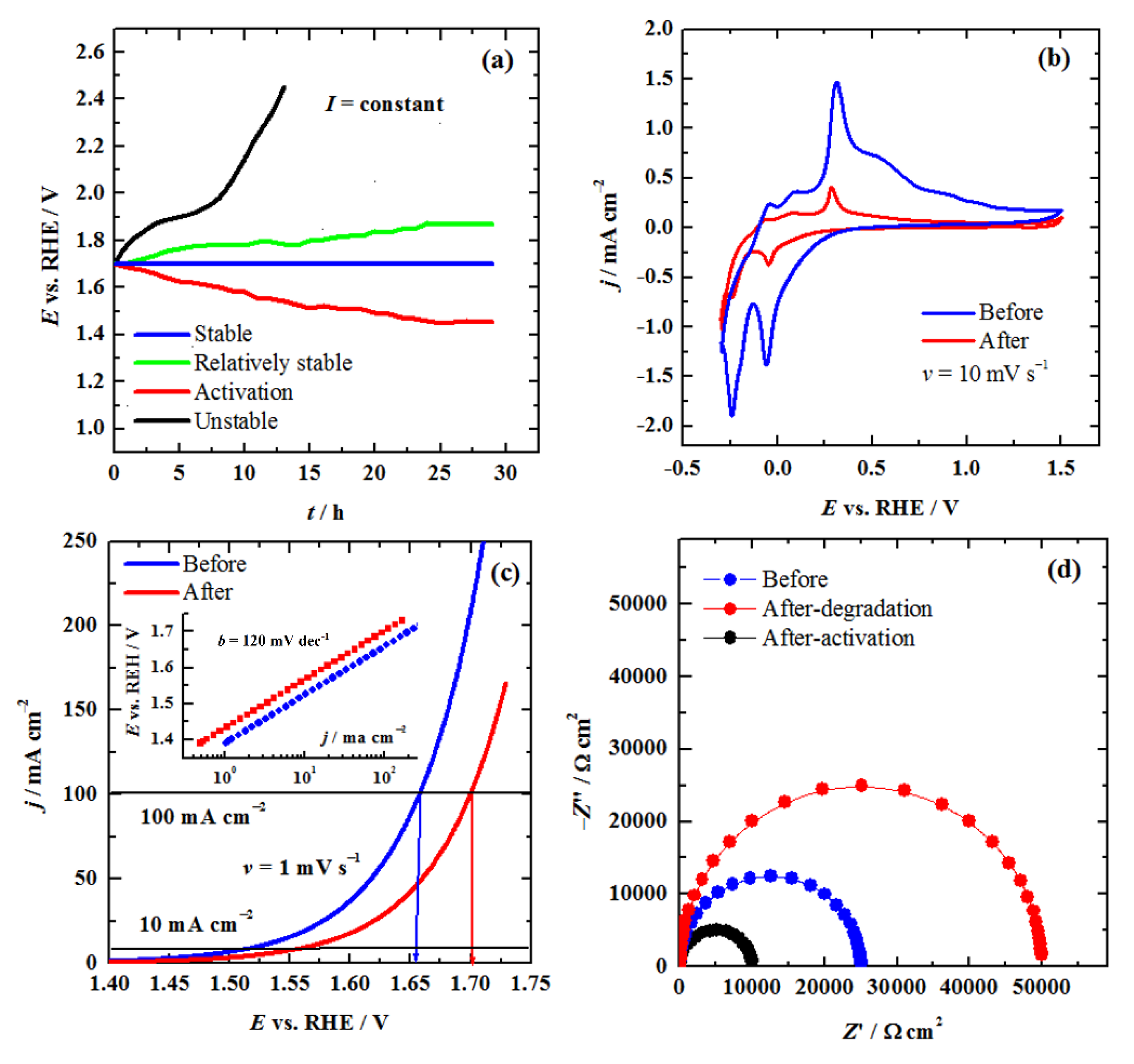
Among others, the stability test is of crucial importance. In many papers, it can be seen that, for example, authors investigated stability with 10 mA cm–2, for ~15 h, and conclude that excellent stability is achieved. For electrodeposited NiFe alloy, using cronopotentiometry with 10 mA cm–2 during 15 h shows a potential increase of only 20 mV, while with 100 mA cm–2 almost 150 mV [73]. During the stability test, a few characteristic responses can be seen, as shown in Figure 4a. For instance, good stability is when potentials are practically not changing over time. Sometimes, a potential decrease that is an indication of the surface formation of the more active species, which accelerates OER. When potentials increase over time, but not considerably, is indicate that slow surface reconstruction occurs, and probably at prolonged time, the catalyst can become inactive. The worst case is when potential increases rapidly during a short period of time, the catalyst is useless. Stability test should be performed with current density of about 100-200 mA cm–2 over 24 h or more, high enough to provoke considerable surface change and to get some information about stability. Avoid using low current densities 5-10 mA cm–2, it can show extraordinary stability over 100 h, but to be instable at operational conditions. Also, in some papers, it can be seen stability of the electrode is with 0.5 to 1 A cm–2. Under such high current, oxygen evolution is considerably fast, and oxygen bubbles are formed and detached rapidly, so the measured values of the potentials will be highly unstable and scattered. If in the paper under such conditions someone sees a horizontal straight line, something is wrong. Also, high current produces Joule heat, and cooling or maintaining a constant temperature of the electrolyte with a thermostat is necessary. The potential should always be corrected for IR drop, from the impedance measurements, or using an instrument softer, for example, the current interrupt method. After the stability test, analysis of electrolyte with Inductively Coupled Plasma Mass Spectrometry (ICP-MS), an analytical technique used to detect trace and ultra-trace amounts of possibly dissolved metals, is highly recommended.
Before the stability test, cyclic voltammetry should be used first to investigate possible redox reactions proceeding oxygen evolution. The potential window should be from hydrogen to oxygen evolution potentials. It is recommended that the CV starts from negative potentials by holding potentials from 300 to 1000 s. The CV should be repeated four to five times to obtain stable behavior. The sweep rate should be 5 mV s–1 to 10 mV s–1, which allows slow, solid-state limited reaction peaks to be seen. Using 50 mV s–1 or 100 mV s–1 can mask some peaks. The cyclic voltammetry should be performed, before and after the stability test, as shown in Figure 4b for the electrode that does not show good performance. For a good electrode, the charge should not change significantly, but some new peaks could be seen, due to structural changes of the surface layer. After the CV, polarization measurement should be performed. Potential should be held at ~1.3 V vs. RHE for ~600 s, and using a slow sweep, e.g., 1 mV s–1 (standards recommended 0.125 mV s–1, but it takes a long time). Do not use 20 mV s–1 or 50 1 mV s–1, because electrodes cannot reach steady–state, and activity could be much better than with 1 mV s–1. Polarization curve has to be recorded for the current densities of 150 to 200 mA cm–2, at higher current densities, due to fast oxygen bubble formations, the polarization curve will be scattered. It is recommended to record two polarization measurements to see reproducibility. After the stability test, another polarization curve should be recorded, and the results have to be similar as before the stability test. Figure 4c shows simulated polarization curves, before and after stability test, for a catalyst that decreases activity. If you got such a result, give up and search for a new catalyst. If the polarization curve did not show significant variations, the catalyst can be considered as potentially good. Always report potentials, or overpotentials (η = E – 1.23) at 10 mA cm–2 and 100 mA cm–2, which is standard in literature. The best case is that the catalyst increases activity. Polarization curves have to be shown also as a Tafel plot, as a separate figure, or as an inset, as shown in Figure 4c. From the obtained Tafel slope do not comment mechanism, it require more experiments. Electrochemical impedance spectroscopy can be performed at constant potential, determined from a polarization curve for the current density of ~20 to 50 mA cm–2, e.g., 1.4 V to 1.6 V, before and after stability test. Figure 4d shows the characteristic Nyquist plot before stability test, after, for the case of decreased activity (increase of Z’), and activated electrode (decrease of Z’). Using the appropriate equivalent electric circuit, by fitting impedance data, a lot of important parameters could be obtained.
If the catalyst shows good electrochemical characteristics, the following non-electrochemical techniques should be used to characterize the bulk and surface of the catalyst. For such characterizations, the initial sample and the sample after the stability test should be characterized.
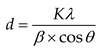
X-ray diffraction (XRD) is a powerful, non-destructive analytical technique used by scientists to determine the atomic and molecular structure of crystalline materials. By firing X-rays at a sample and measuring the angles and intensity at which the X-rays scatter, XRD generates a unique "fingerprint" of the material's internal crystal lattice. Unfortunately, X-rays penetration depth is in the order of μm, so it is usually used for bulk characterization, and there is no need to use this technique after the stability test. After recording XRD, it is recommended that the researcher who characterizes the sample use a softer usually supplied with the equipment to determine the phases of the sample. Otherwise, it is difficult to use the PDF cards to characterize a sample. If you got the phase of the sample, but, if crystalline size is not determined, it is not difficult to determine it using the Scherrer equation
Preprints 220444 i011
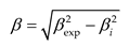
where: d is the average crystallite size (nm), K is the shape factor (typically 0.89–0.94; often taken as 0.9), λ is the X-ray wavelength (nm, for Cu Kα, λ = 0.15406 nm), β is the full width at half maximum (FWHM) of the diffraction peak corrected for instrumental broadening (radians), θ is the Bragg angle (radians).
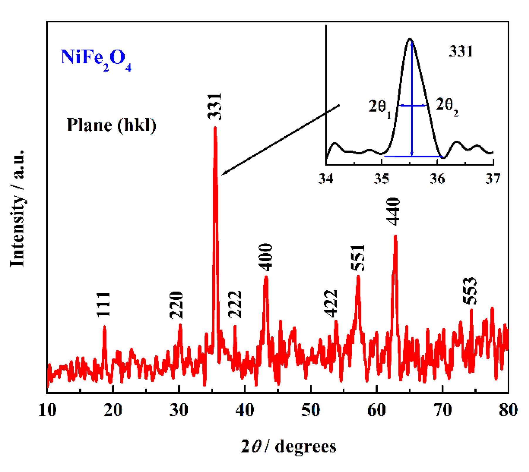
In Figure 5 [74], the XRD of spinel NiFe2O4 is given. Typical crystals (hkl) are marked, corresponding to the spinel phase. To determine crystalline size, it is necessary to know peak maximum, 2θ, and FWHM, which can be determined as 2θ2 – 2θ1 that is, in presented case, 0.3 eV, and 2θ is 35.5o. To convert in radians, the following should be used: θ (radians) = θ (degrees) × π / 180. In a specific case, for 2θ is 35.5o, so 35.5o/2 = 17.75o, and θ is 0.310 radians.
Correction for instrumental broadening βi:
Preprints 220444 i012
where both β values must be in radians. For many cases, using conventional Cu Kα diffractometers, βi instrumental is often around 0.05–0.10° (2θ). If crystallite sizes are around 10–50 nm, measured FWHM values are often 0.2–1.0°, so assuming βi ≈ 0.05–0.10° usually does not change the result dramatically. For crystallite sizes above ~100 nm, instrumental correction becomes much more important. So, in presented case, measured FWHM = 0.310°, instrumental broadening = 0.10°:
Preprints 220444 i013
Notice that the correction is relatively small when the peak is already broad. Converting FWHM from degrees to radians, β (radians) = β (degrees) × π / 180 = 0.00512 rad. Applying the Scherrer equation, it can be obtained:
Preprints 220444 i014
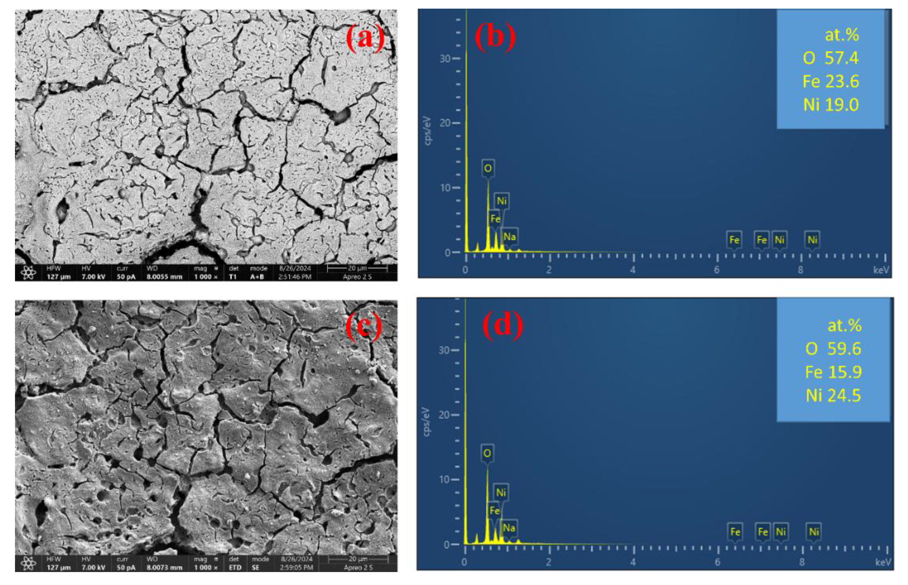
Scanning Electron Microscopy coupled with Energy-Dispersive X-ray Spectroscopy (SEM-EDS) is an analytical technique that pairs high-resolution surface imaging with elemental analysis. It works by bombarding a sample with an electron beam, which generates characteristic X-rays used to map and quantify the chemical composition of microscopic areas. The SEM coupled with EDS is a powerful tool for catalyst characterization. Depending on X-rays energy, EDS could be near-surface characterization, for 2-7 keV, or go beyond 10 keV. With low energy, the penetration depth is limited to 100-300 nm, while at higher energy to μm. Penetration depth is usually given in the instrument's manual. Recording the EDS with different X-ray energies through the sample, it is plausible to determine the metal concentration through the sample. Figure 6 presents SEM and EDS at 7 keV of spinel NiFe2O4 before and after stability test at 100 mA cm–2 for 24 h. From SEM it can be seen that after the stability test, morphology is changed, and from EDS that Fe concentration decreases, while Ni concentration increases, that could be indication of iron dissolution or high surface or near surface reconstructions.
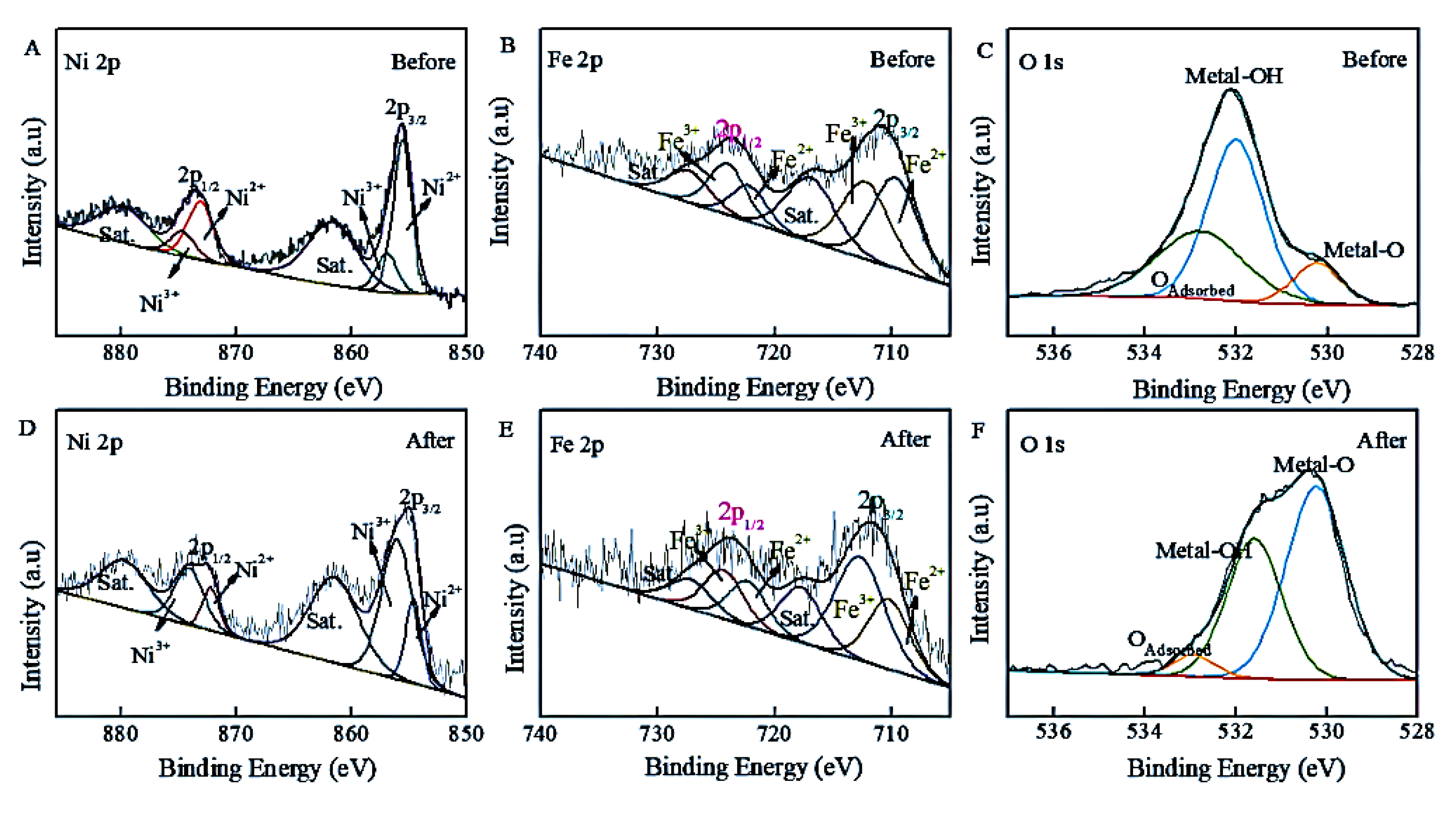
X-ray photoelectron spectroscopy (XPS) is a powerful technique for surface catalyst characterization. The separately prepared sample without characterization, and after the stability test, should be examined. From the XPS survey scan (0–1100 eV), the surface elemental composition of the NiFe catalyst could be determined. The high-resolution spectra shown in Figure 7 present a Ni 2p spectrum (binding energy range ~850–880 eV) that reveals the oxidation states of nickel (e.g., metallic Ni, Ni²⁺, or Ni³⁺) and the presence of satellite features characteristic of Ni(OH)₂ or NiO. The Fe 2p spectrum (~705–730 eV) indicates the dominant iron species (typically Fe³⁺ oxide/hydroxide) and possible Fe²⁺ contributions. The O 1s spectrum (~528–535 eV) distinguishes between lattice oxygen (M–O), hydroxyl groups (M–OH), and adsorbed water [75]. By fitting the spectra with appropriate software, the relative amounts of different chemical states and the surface enrichment of Fe or Ni can be quantified.

6. Outlook and Perspective

Even the great success in the research of NiFe catalyst for oxygen evolution reaction in laboratory conditions, nickel, especially Raney nickel, as a highly porous, catalytically active form of nickel, and stainless-steel electrodes continue to serve as industrial benchmarks, for alkaline water electrolysis [76]. Realization of the long-term stability of OER is a serious challenge, and a more comprehensive understanding of NiFe catalytic mechanisms is required to reach this goal [22]. The impressive catalytic activity of nickel-iron (NiFe) (oxy)hydroxides for the oxygen evolution reaction (OER) is consistently undermined by their limited operational stability. The predominant source of this instability is the selective and continuous leaching of iron from the catalyst lattice under harsh alkaline conditions, which not only reduces the Fe/Ni ratio but also causes irreversible structural collapse of the active layered double hydroxide (LDH) architecture [35,37]. This loss of the critical Fe sites weakens the synergistic Ni–O–Fe motif and leads to a progressive increase in the overpotential and charge transfer resistance. To address this fundamental challenge, doping with specific transition metals has emerged as a highly effective strategy to electronically and structurally fortify the NiFe framework. Doping with different transition metals (e.g, Co, Mn, Mo, Ag, Cu, etc.) strengthens the NiFe framework and improves resistance to phase deviations and metal leaching [62,68]. Each dopant offers a distinct stabilization mechanism that enhances both activity and durability. Molybdenum (Mo), as a high-valence electron donor, significantly elevates the valence states of both Ni and Fe, while shifting the d-band center of the metal active sites, which improves electrical conductivity and overall OER kinetics [79,80]. Cobalt (Co) dopants are particularly potent, as they facilitate a unique "dynamic ferrous iron regeneration" pathway that chemically restores leached Fe²⁺ species into the catalyst layer, a process that has enabled a NiFeCo LDH to maintain stable water oxidation for over 120 hours [81]. Copper (Cu) functions as an efficient "electron donor," optimizing the adsorption-free energy of key OER intermediates like *OOH, thereby synergistically boosting the intrinsic activity and stability of the resulting trimetallic NiFeCu LDH structure [82]. Silver (Ag), though less common, has proven effective by tailoring the atomically local electric field around NiFe active sites, enhancing oxygen intermediate adsorption [83]. By tackling the root cause of iron dissolution through these tailored electronic and chemical doping strategies, NiFe-based catalysts are rapidly evolving into robust and durable anodes, moving them ever closer to the long-term stability demands of industrial alkaline water electrolysis. Also, incorporating NiFe LDHs and electrodeposited NiFe layers into a conductive medium provides mechanical reinforcement and improves electron transport, thereby enhancing durability [84]. Applying protective coatings helps mitigate dissolution and suppress surface alterations [68,69]. Generally, these approaches considerably enhance the stability and working lifespan of NiFe LDH and electrodeposited NiFe OER catalysts in alkaline environments, carrying them more rapidly to application in large-scale alkaline water electrolysis. Mitigating these degradation pathways requires a holistic approach combining structural stabilization (e.g., spinel frameworks), electronic regulation, and electrolyte engineering.

Author Contributions

Conceptualization, B.G. and A.P.; methodology, B.G. and A.P.; writing—original draft preparation, B.G and AP.; writing—review and editing, B.G. and. A.P.; visualization, B.G. and A.P; funding acquisition, B.G.

Funding

The support is provided by the Ministry of Education, Science and Technological Development of the Republic of Serbia, Contract No. 451-03-34/2026-03/200135.

Data Availability Statement

The data will be provide from corresponding author on reasonable request.

Conflicts of Interest

The authors declare no conflicts of interest.

References

  1. Holechek, J.L.; Geli, H.M.E.; Sawalhah, M.N.; Valdez, R. A Global Assessment: Can Renewable Energy Replace Fossil Fuels by 2050? Sustainability 2022, 14, 4792. [Google Scholar] [CrossRef]
  2. World Meteorological Organization (WMO). Record carbon emissions highlight urgency of Global Greenhouse Gas Watch. Available online: https://wmo.int/media/news/record-carbon-emissions-highlight-urgency-of-global-greenhouse-gas-watch (accessed on 29 May 2026).
  3. Elazab, M.A.; Elgohr, A.T.; Bassyouni, M.; Kabeel, A.E.; Attia, M.E.H.; Elshaarawy, M.K.; Hamed, A.K.; Alzahrani, H.A.H. Green Hydrogen: Unleashing the Potential for Sustainable Energy Generation. Results Eng. 2025, 27, 106031. [Google Scholar] [CrossRef]
  4. Nnabuife, S.G.; Darko, C.K.; Obiako, P.C.; Kuang, B.; Sun, X.; Jenkins, K. A Comparative Analysis of Different Hydrogen Production Methods and Their Environmental Impact. Clean. Technol. 2023, 5(4), 1344–1380. [Google Scholar] [CrossRef]
  5. Blumberg, T.; Morosuk, T.; Tsatsaronis, G. A Comparative Exergoeconomic Evaluation of the Synthesis Routes for Methanol Production from Natural Gas. Appl. Sci. 2017, 7(12), 1213. [Google Scholar] [CrossRef]
  6. Franco, A.; Giovannini, C. Recent and Future Advances in Water Electrolysis for Green Hydrogen Generation: Critical Analysis and Perspectives. Sustainability 2023, 15, 16917. [Google Scholar] [CrossRef]
  7. Tüysüz, H. Alkaline Water Electrolysis for Green Hydrogen Production. Acc. Chem. Res. 2024, 57(4), 558–567. [Google Scholar] [CrossRef] [PubMed]
  8. Anand, C.; Chandraja, B.; Nithiya, P.; Akshaya, M.; Tamizhdurai, P.; Shoba, G.; Subramani, A.; Kumaran, R.; Yadav, K.K.; Gacem, A.; Bhutto, J.K.; Alreshidi, M.A.; Alam, M.W. Green hydrogen for a sustainable future: A review of production methods, innovations, and applications. Int. J. Hydrogen Energy 2025, 111, 319–341. [Google Scholar] [CrossRef]
  9. Bhandari, R.; Adhikari, N. A comprehensive review on the role of hydrogen in renewable energy systems. Int. J. Hydrogen Energy 2024, 82, 923–951. [Google Scholar] [CrossRef]
  10. Zhu, Y.; Keoleian, G.A.; Cooper, D.R. The role of hydrogen in decarbonizing U.S. industry: A review. Renew. Sustain. Energy Rev. 2025, 214, 115392. [Google Scholar] [CrossRef]
  11. Bhuiyan, M.M.H.; Siddique, Z. Hydrogen as an alternative fuel: A comprehensive review of challenges and opportunities in production, storage, and transportation. Int. J. Hydrogen Energy 2025, 102, 1026–1044. [Google Scholar] [CrossRef]
  12. Şahin, M.E. An Overview of Different Water Electrolyzer Types for Hydrogen Production. Energies 2024, 17(19), 4944. [Google Scholar] [CrossRef]
  13. Chatenet, M.; Pollet, B.G.; Dekel, D.R.; Dionigi, F.; Deseure, J.; Millet, P.; Braatz, R.D.; Bazant, M.Z.; Eikerling, M.; Staffell, I.; Balcombe, P.; Shao-Horn, Y.; Schäfer, H. Water electrolysis: from textbook knowledge to the latest scientific strategies and industrial developments. Chem. Soc. Rev. 2022, 51, 4583–4762. [Google Scholar] [CrossRef] [PubMed]
  14. IRENA. Green hydrogen cost reduction: scaling up electrolysers to meet the 1.5°C climate goal. International Renewable Energy Agency: Abu Dhabi, 2020; Available online: https://www.irena.org/-/media/Files/IRENA/Agency/Publication/2020/Dec/IRENA_Green_hydrogen_cost_2020.pdf (accessed on 29 May 2026).
  15. Li, Y.-F.; Li, J.-L.; Liu, Z.-P. Structure and catalysis of NiOOH: Recent advances on atomic simulation. J. Phys. Chem. C 2021, 125, 27033–27045. [Google Scholar] [CrossRef]
  16. Quiroz, S.G.; Cartagena, S.; Calderón, J.A. Enhancement of oxygen evolution performance of water splitting at high current density by novel electrodeposited NiFe-LDH coatings. Electrochim. Acta 2025, 528, 146332. [Google Scholar] [CrossRef]
  17. Ren, X.; Zhai, Y.; Yang, N.; Wang, B.; Liu, S. Lattice oxygen redox mechanisms in the alkaline oxygen evolution reaction. Adv. Funct. Mater. 2024, 34. [Google Scholar] [CrossRef]
  18. Xin, S.; Tang, Y.; Jia, B.; Zhang, Z.; Li, C.; Bao, R.; Li, C.; Yi, J.; Wang, J.; Ma, T. Coupling adsorbed evolution and lattice oxygen mechanism in Fe-Co(OH)₂/Fe₂O₃ heterostructure for enhanced electrochemical water oxidation. Adv. Funct. Mater. 2023, 33(45), 2305243. [Google Scholar] [CrossRef]
  19. Yin, Z.-H.; Liu, H.; Hu, J.-S.; Wang, J.-J. The breakthrough of oxide pathway mechanism in stability and scaling relationship for water oxidation. Natl. Sci. Rev. 2024, 11, nwae362. [Google Scholar] [CrossRef] [PubMed]
  20. Wang, Z.; Goddard, W.A.; Xiao, H. Potential-dependent transition of reaction mechanisms for oxygen evolution on layered double hydroxides. Nat. Commun. 2023, 14, 4228. [Google Scholar] [CrossRef] [PubMed]
  21. De Araújo, J.F.; Dionigi, F.; Merzdorf, T.; Oh, H.; Strasser, P. Evidence of Mars-Van-Krevelen mechanism in the electrochemical oxygen evolution on Ni-based catalysts. Angew. Chem. Int. Ed. 2021, 60, 14981–14988. [Google Scholar] [CrossRef] [PubMed]
  22. Chen, F.-Y.; Wu, Z.-Y.; Adler, Z.; Wang, H. Stability challenges of electrocatalytic oxygen evolution reaction: From mechanistic understanding to reactor design. Joule 2021, 5, 1704–1731. [Google Scholar] [CrossRef]
  23. Fabbri, E.; Schmidt, T.J. Oxygen Evolution Reaction—The Enigma in water electrolysis. ACS Catal. 2018, 8, 9765–9774. [Google Scholar] [CrossRef]
  24. Li, P.; Jang, H.; Zhang, J.; Tian, M.; Chen, S.; Yuan, B.; Wu, Z.; Liu, X.; Cho, J. A Metal-Free N and P-Codoped carbon nanosphere as bifunctional electrocatalyst for rechargeable Zinc-Air batteries. ChemElectroChem 2018, 6(2), 393–397. [Google Scholar] [CrossRef]
  25. Tachikawa, T.; Beniya, A.; Shigetoh, K.; et al. Relationship Between OER Activity and Annealing Temperature of Sputter-Deposited Flat IrO₂ Thin Films. Catal. Lett. 2020, 150, 1976–1984. [Google Scholar] [CrossRef]
  26. Palani, R.; Anitha, V.; Karuppiah, C.; Rajalakshmi, S.; Li, Y.-J.J.; Hung, T.-F.; Yang, C.-C. Imidazolatic-Framework Bimetal Electrocatalysts with a Mixed-Valence Surface Anchored on an rGO Matrix for Oxygen Reduction, Water Splitting, and Dye Degradation. ACS Omega 2021, 6(24), 16029–16042. [Google Scholar] [CrossRef] [PubMed]
  27. Chen, H.; Huang, X.; Zhou, L.-J.; Li, G.-D.; Fan, M.; Zou, X. Electrospinning Synthesis of Bimetallic Nickel–Iron Oxide/Carbon Composite Nanofibers for Efficient Water Oxidation Electrocatalysis. ChemCatChem 2016, 8, 992. [Google Scholar] [CrossRef]
  28. Si, S.; Hu, H.-S.; Liu, R.-J.; Xu, Z.-X.; Wang, C.-B.; Feng, Y.-Y. Co–NiFe layered double hydroxide nanosheets as an efficient electrocatalyst for the electrochemical evolution of oxygen. Int. J. Hydrogen Energy 2020, 45(16), 9368–9379. [Google Scholar] [CrossRef]
  29. Corrigan, D.A. The catalysis of the oxygen evolution reaction by iron impurities in thin-film nickel oxide electrodes. J. Electrochem. Soc. 1987, 134(2), 377–384. [Google Scholar] [CrossRef]
  30. Trotochaud, L.; Young, S.L.; Ranney, J.K.; Boettcher, S.W. Nickel–iron oxyhydroxide oxygen-evolution electrocatalysts: the role of intentional and incidental iron incorporation. J. Am. Chem. Soc. 2014, 136, 6744–6753. [Google Scholar] [CrossRef] [PubMed]
  31. Gong, M.; Li, Y.; Wang, H.; Liang, Y.; Wu, J.Z.; Zhou, J.; Wang, J.; Regier, T.; Wei, F.; Dai, H. An advanced Ni–Fe layered double hydroxide electrocatalyst for water oxidation. J. Am. Chem. Soc. 2013, 135, 8452–8455. [Google Scholar] [CrossRef] [PubMed]
  32. Mohammed-Ibrahim, J. A review on NiFe-based electrocatalysts for efficient alkaline oxygen evolution reaction. J. Power Sources 2020, 448, 227375. [Google Scholar] [CrossRef]
  33. Kulkarni, S.S.; Khande, G.L.; Gunjakar, J.L.; Koli, V.B. Advances in Layered Double Hydroxide (LDH)-Based Materials for Electrocatalytic Nitrogen Reduction to Ammonia: A Comprehensive Review. Nitrogen 2025, 6, 106. [Google Scholar] [CrossRef]
  34. Guo, D.; Chi, J.; Yu, H.; Jiang, G.; Shao, Z. Self-Supporting NiFe Layered Double Hydroxide "Nanoflower" Cluster Anode Electrode for an Efficient Alkaline Anion Exchange Membrane Water Electrolyzer. Energies 2022, 15(13), 4645. [Google Scholar] [CrossRef]
  35. Tyndall, D.; Craig, M.J.; Gannon, L.; McGuinness, C.; McEvoy, N.; Roy, A.; García Melchor, M.; Browne, M.P.; Nicolosi, V. Demonstrating the source of inherent instability in NiFe LDH based OER electrocatalysts. J. Mater. Chem. A 2023, 11, 4067–4077. [Google Scholar] [CrossRef] [PubMed]
  36. Li, Z.; Shao, M.; An, H.; Wang, Z.; Xu, S.; Wei, M.; Evans, D.G.; Duan, X. Fast electrosynthesis of Fe containing layered double hydroxide arrays toward highly efficient electrocatalytic oxidation reactions. Chem. Sci. 2015, 6, 6624–6631. [Google Scholar] [CrossRef] [PubMed]
  37. Liu, Q.; Wang, Y.; Lu, X. Construction of NiFe Layered Double Hydroxides Arrays as Robust Electrocatalyst for Oxygen Evolution Reaction. Catalysts 2023, 13(3), 586. [Google Scholar] [CrossRef]
  38. Li, T.; Liu, W.; Xin, H.; Sha, Q.; Xu, H.; Kuang, Y.; Sun, X. Large-Scale and Simple Synthesis of NiFe(OH)ₓ Electrode Derived from Raney Ni Precursor for Efficient Alkaline Water Electrolyzer. Catalysts 2024, 14(5), 296. [Google Scholar] [CrossRef]
  39. Li, G.; Zhang, J.; Li, L.; Yuan, C.; Weng, T.-C. Boosting the Electrocatalytic Activity of Nickel-Iron Layered Double Hydroxide for the Oxygen Evolution Reaction by Terephthalic Acid. Catalysts 2022, 12, 258. [Google Scholar] [CrossRef]
  40. Zhang, Z.; Zhou, D.; Bao, X.; Yu, H.; Huang, B. Thermal decomposition behavior of nickel-iron hydrotalcite and its electrocatalytic properties of oxygen reduction and oxygen evolution reactions. Int. J. Hydrogen Energy 2018, 43(45), 20734–20738. [Google Scholar] [CrossRef]
  41. Quiroz, S.G.; Cartagena, S.; Calderón, J.A. Enhancement of oxygen evolution performance of water splitting at high current density by novel electrodeposited NiFe-LDH coatings. Electrochim. Acta 2025, 528, 146332. [Google Scholar] [CrossRef]
  42. Lu, X.; Zhao, C. Electrodeposition of hierarchically structured three-dimensional nickel–iron electrodes for efficient oxygen evolution at high current densities. Nat. Commun. 2015, 6, 6616. [Google Scholar] [CrossRef] [PubMed]
  43. Swierk, J.R.; Klaus, S.; Trotochaud, L.; Bell, A.T.; Tilley, T.D. Electrochemical study of the energetics of the oxygen evolution reaction at nickel iron (oxy)hydroxide catalysts. J. Phys. Chem. C 2015, 119(33), 19022–19029. [Google Scholar] [CrossRef]
  44. Wu, X.; Du, Y.; An, X.; Xie, X. Fabrication of NiFe layered double hydroxides using urea hydrolysis — Control of interlayer anion and investigation on their catalytic performance. Catal. Commun. 2014, 50, 44–48. [Google Scholar] [CrossRef]
  45. Zuber, A.; Oikonomou, I.M.; Gannon, L.; Chunin, I.; Reith, L.; Can, B.; Lounasvuori, M.; Schultz, T.; Koch, N.; McGuinness, C.; Menezes, P.W.; Nicolosi, V.; Browne, M.P. Effect of the precursor metal salt on the oxygen evolution reaction for NiFe oxide materials. ChemElectroChem 2024, 11(17). [Google Scholar] [CrossRef]
  46. Hou, C.; Cui, Z.; Zhang, S.; Yang, W.; Gao, H.; Luo, X. Rapid large scale synthesis of ultrathin NiFe LDH nanosheets with tunable structures as robust oxygen evolution electrocatalysts. RSC Adv. 2021, 11, 37624–37630. [Google Scholar] [CrossRef] [PubMed]
  47. Iwasaki, T.; Yoshii, H.; Nakamura, H.; Watano, S. Simple and rapid synthesis of Ni–Fe layered double hydroxide by a new mechanochemical method. Appl. Clay Sci. 2012, 58, 120–124. [Google Scholar] [CrossRef]
  48. Molina-Muriel, M.; Zignani, S.C.; Goberna-Ferrón, S.; Ribera, A.; Aricò, A.S.; García, H. Efficient NiFe-Layered double hydroxide electrocatalyst synthesized via a solvent-free mechanochemical method for oxygen evolution reaction. ACS Omega 2025, 10(22), 22671–22678. [Google Scholar] [CrossRef] [PubMed]
  49. Del Rosario, J.A.D.; Li, G.; Labata, M.F.M.; Ocon, J.D.; Chuang, P.-Y.A. Unravelling the roles of alkali-metal cations for the enhanced oxygen evolution reaction in alkaline media. Appl. Catal. B 2021, 288, 119981. [Google Scholar] [CrossRef]
  50. Garcia, A.C.; Touzalin, T.; Nieuwland, C.; Perini, N.; Koper, M.T.M. Enhancement of oxygen evolution activity of nickel oxyhydroxide by electrolyte alkali cations. Angew. Chem. Int. Ed. 2019, 58, 12999–13003. [Google Scholar] [CrossRef] [PubMed]
  51. Zhuang, D.; Riera, M.; Zhou, R.; Deary, A.; Paesani, F. Hydration structure of Na⁺ and K⁺ ions in solution predicted by data-driven many-body potentials. J. Phys. Chem. B 2022, 126(45), 9349–9360. [Google Scholar] [CrossRef] [PubMed]
  52. Li, D.; Park, E.J.; Zhu, W.; Shi, Q.; Zhou, Y.; Tian, H.; Lin, Y.; Serov, A.; Zulevi, B.; Baca, E.D.; Fujimoto, C.; Chung, H.T.; Kim, Y.S. Highly quaternized polystyrene ionomers for high performance anion exchange membrane water electrolysers. Nat. Energy 2020, 5(5), 378–385. [Google Scholar] [CrossRef]
  53. Kubo, N.M.; Ketter, F.; Palkovits, S.; Palkovits, R. Nickel and Commercially Available Nickel-Containing Alloys as Electrodes for the Electrochemical Oxygen Evolution. ChemElectroChem 2024, 11, e202300460. [Google Scholar] [CrossRef]
  54. Luo, Y.; He, Y.; Li, J.; Wei, S.; Chen, L. Reinforced lattice oxygen mechanism of NiFe-LDH@Fe₂O₃@NF by optimizing the adsorption of oxygen intermediates for efficient water electrolysis. J. Environ. Chem. Eng. 2025, 13, 115497. [Google Scholar] [CrossRef]
  55. Li, L.; Bai, L.; She, S.; Chen, G.; Huang, H. Mixed ionic conductor brings extra gain in oxygen-evolving activity of NiFe hydroxide electrocatalyst at practical working temperature. Appl. Catal. B 2025, 371, 125271. [Google Scholar] [CrossRef]
  56. Pascuzzi, M.E.C.; Man, A.J.W.; Goryachev, A.; Hofmann, J.P.; Hensen, E.J.M. Investigation of the stability of NiFe-(oxy)hydroxide anodes in alkaline water electrolysis under industrially relevant conditions. Catal. Sci. Technol. 2020, 10, 5593–5601. [Google Scholar] [CrossRef]
  57. Han, Y.; Wang, J.; Liu, Y.; Li, T.; Wang, T.; Li, X.; Ye, X.; Li, G.; Li, J.; Hu, W.; Deng, Y. Stability challenges and opportunities of NiFe-based electrocatalysts for oxygen evolution reaction in alkaline media. Carbon Neutraliz. 2024, 3(2), 172–198. [Google Scholar] [CrossRef]
  58. Goldsmith, Z.K.; Young, S.L.; Ranney, J.K.; Boettcher, S.W. Characterization of NiFe Oxyhydroxide Electrocatalysts by Integrated Electronic Structure Calculations and Spectroelectrochemistry. Proc. Natl. Acad. Sci. USA 2017, 114(12), 3050–3055. [Google Scholar] [CrossRef] [PubMed]
  59. El Boumlasy, S.; Pascale, M.; De Luca, O.; Caruso, T.; Mirabella, S.; Terrasi, A.; Aricò, A.S.; Ruffino, F. Highly efficient and stable NiFe oxide-based electrocatalysts for oxygen evolution in alkaline and saline solutions. Appl. Surf. Sci. Adv. 2025, 28, 100809. [Google Scholar] [CrossRef]
  60. Lin, Z.; Bu, P.; Xiao, Y.; Gao, Q.; Diao, P. β- and γ-NiFeOOH electrocatalysts for an efficient oxygen evolution reaction: an electrochemical activation energy aspect. J. Mater. Chem. A 2022, 10, 20847–20855. [Google Scholar] [CrossRef]
  61. Feng, Z.; Wang, P.; Cheng, Y.; Mo, Y.; Luo, X.; Liu, P.; Guo, R.; Liu, X. Recent progress on NiFe₂O₄ spinels as electrocatalysts for the oxygen evolution reaction. J. Electroanal. Chem. 2023, 946, 117703. [Google Scholar] [CrossRef]
  62. He, L.; Zhou, Y.; Wang, M.; Li, S.; Lai, Y. Recent Progress on Stability of Layered Double Hydroxide-Based Catalysts for Oxygen Evolution Reaction. Nanomaterials 2024, 14, 1533. [Google Scholar] [CrossRef] [PubMed]
  63. Iqbal, S.; Ehlers, J.C.; Hussain, I.; Zhang, K.; Chatzichristodoulou, C. Trends and industrial prospects of NiFe-layered double hydroxide for the oxygen evolution reaction. Chem. Eng. J. 2024, 499, 156219. [Google Scholar] [CrossRef]
  64. Plevová, M.; Hnát, J.; Bouzek, K. Electrocatalysts for the Oxygen Evolution Reaction in Alkaline Media: A Comparative Review. J. Power Sources 2021, 507, 230072. [Google Scholar] [CrossRef]
  65. Soni, A.; Maurya, S.K.; Malviya, M. Exploring electrocatalysts for oxygen evolution: A comprehensive comparative review in alkaline and acidic medium. J. Power Sources 2025, 636, 236571. [Google Scholar] [CrossRef]
  66. Li, L.-F.; Li, Y.-F.; Liu, Z.-P. Oxygen Evolution Activity on NiOOH Catalysts: Four-Coordinated Ni Cation as the Active Site and the Hydroperoxide Mechanism. ACS Catal. 2020, 10, 2581–2590. [Google Scholar] [CrossRef]
  67. Li, X.; Ruan, M.; Shen, Y.; Wen, M.; Li, Z.; Yin, H.; Chen, F.; Cheng, Y.; Lei, P.; Qian, L. Phase locking of NiOOH@β-Ni(Fe)OOH reconstructed simultaneously for robust oxygen evolution at high current density. ACS Appl. Mater. Interfaces 2025, 17(31), 44562–44572. [Google Scholar] [CrossRef] [PubMed]
  68. Han, S.; Yoon, J. Strategies for Advancing Electrodeposited Co-Based Oxygen Evolution Catalysts from Alkaline to Pure-Water Conditions. ACS Mater. Lett. 2025, 7(9), 3128–3140. [Google Scholar] [CrossRef]
  69. McCrory, C.C.L.; Jung, S.; Peters, J.C.; Jaramillo, T.F. Benchmarking heterogeneous electrocatalysts for the oxygen evolution reaction. J. Am. Chem. Soc. 2013, 135(45), 16977–16987. [Google Scholar] [CrossRef] [PubMed]
  70. Vital, M.; Van Beek Pedersen, T.; Molander, J.; Jakobsen, R.; Tobler, D.J.; Dideriksen, K. Dissolution kinetics for the Fe(II)-Fe(III) layered double hydroxide, green rust. Appl. Clay Sci. 2025, 272, 107814. [Google Scholar] [CrossRef]
  71. De Koninck, M.; Bélanger, D. The electrochemical generation of ferrate at pressed iron powder electrode: comparison with a foil electrode. Electrochim. Acta 2003, 48, 1435–1442. [Google Scholar] [CrossRef]
  72. Wu, Y.; Zhang, C.; Fei, Y.; Zheng, Z. The degradation mechanism of NiFe-LDH catalysts in alkaline oxygen evolution reaction at high temperature. Mater. Lett. 2025, 398, 138901. [Google Scholar] [CrossRef]
  73. Elsharkawy, S.; Żabiński, P. Effect of Fe/Ni ratio on electrodeposition of Ni-Fe alloys and their bifunctional catalytic performance in hydrogen and oxygen evolution reactions. J. Power Sources 2025, 660, 238516. [Google Scholar] [CrossRef]
  74. Grgur, B.N.; Popović, A.S. unpublished results. 2025. [CrossRef]
  75. Yu, J.; Fu, X.; Wang, H.; Lu, S.; Li, B. Rational construction of nano-scaled FeOOH/NiFe-LDH for efficient water splitting. Nanomaterials 2025, 15, 949. [Google Scholar] [CrossRef] [PubMed]
  76. Nikolić, V.M.; Dimić-Mišić, K.M.; Maslovara, S.L.; Popović, D.P.; Gigov, M.N.; Krstić, S.S.; Kaninski, M.P.M. Advances in Alkaline Water Electrolysis—The role of in situ ionic activation in green hydrogen production. Catalysts 2026, 16, 98. [Google Scholar] [CrossRef]
  77. Qiao, X.; Zhu, Q.; Hou, G.; Pang, Z.; Kang, H. Pinning effect of lattice Co enhances lattice oxygen regeneration in NiFe-LDH for oxygen evolution reaction. J. Colloid Interface Sci. 2025, 699, 138219. [Google Scholar] [CrossRef] [PubMed]
  78. Xie, X.; Du, L.; Yan, L.; Park, S.; Qiu, Y.; Sokolowski, J.; Wang, W.; Shao, Y. Oxygen evolution reaction in alkaline environment: material challenges and solutions. Adv. Funct. Mater. 2022, 32(21). [Google Scholar] [CrossRef]
  79. Zhang, C.; Wang, J.; Ma, H.; Wang, J.; Xu, R.; Li, G.; Yang, L.; Guo, H. Electronic structure engineering of NiFe hydroxide nanosheets via ion doping for efficient OER electrocatalysis. Chem. Eng. J. 2024, 499, 156430. [Google Scholar] [CrossRef]
  80. Qu, J.; Dong, Y.; Zhang, T.; Zhao, C.; Wei, L.; Guan, X. Impact of bimetallic synergies on Mo-doping NiFeOOH: Insights into enhanced OER activity and reconstructed electronic structure. Front. Energy 2024, 18, 850–862. [Google Scholar] [CrossRef]
  81. Assavachin, S.; Ittisanronnachai, S.; Atithep, T.; Chitterisin, N.; Sawangphruk, M. Dynamic ferrous iron regeneration enables stabilization of NiFeCo layered double hydroxide for enhanced alkaline water oxidation. J. Power Sources 2025, 650, 237494. [Google Scholar] [CrossRef]
  82. Li, J.; Wei, Y.; Zou, L.; Liu, Y.; Li, S.; Luo, Y. Cu dual-site doping: synergistic enhancement of OER activity through LDH and nickel foam interface engineering. New J. Chem. 2025, 49, 17577–17587. [Google Scholar] [CrossRef]
  83. Zhang, X.; Tong, L.; Shi, X.; Li, Z.; Xiao, Z.; Liu, Y.; Zhang, T.; Lin, S. Tailoring atomically local electric field of NiFe layered double hydroxides with Ag dopants to boost oxygen evolution kinetics. J. Colloid Interface Sci. 2024, 668, 502–511. [Google Scholar] [CrossRef] [PubMed]
  84. Silva, A.S.-D.; Hartert, A.; Oestreicher, V.; Romero, J.; Jaramillo-Hernández, C.; Muris, L.J.J.; Thorez, G.; Vieira, B.J.C.; Ducourthial, G.; Fiocco, A.; Legendre, S.; Huck-Iriart, C.; Mizrahi, M.; López-Alcalá, D.; Freiberg, A.T.S.; Mayrhofer, K.J.J.; Waerenborgh, J.C.; Baldoví, J.J.; Cherevko, S.; Varela, M.; Thiele, S.; Lloret, V.; Abellán, G. Scalable synthesis of NiFe-layered double hydroxide for efficient anion exchange membrane electrolysis. Nat. Commun. 2025, 16(1), 6138. [Google Scholar] [CrossRef] [PubMed]
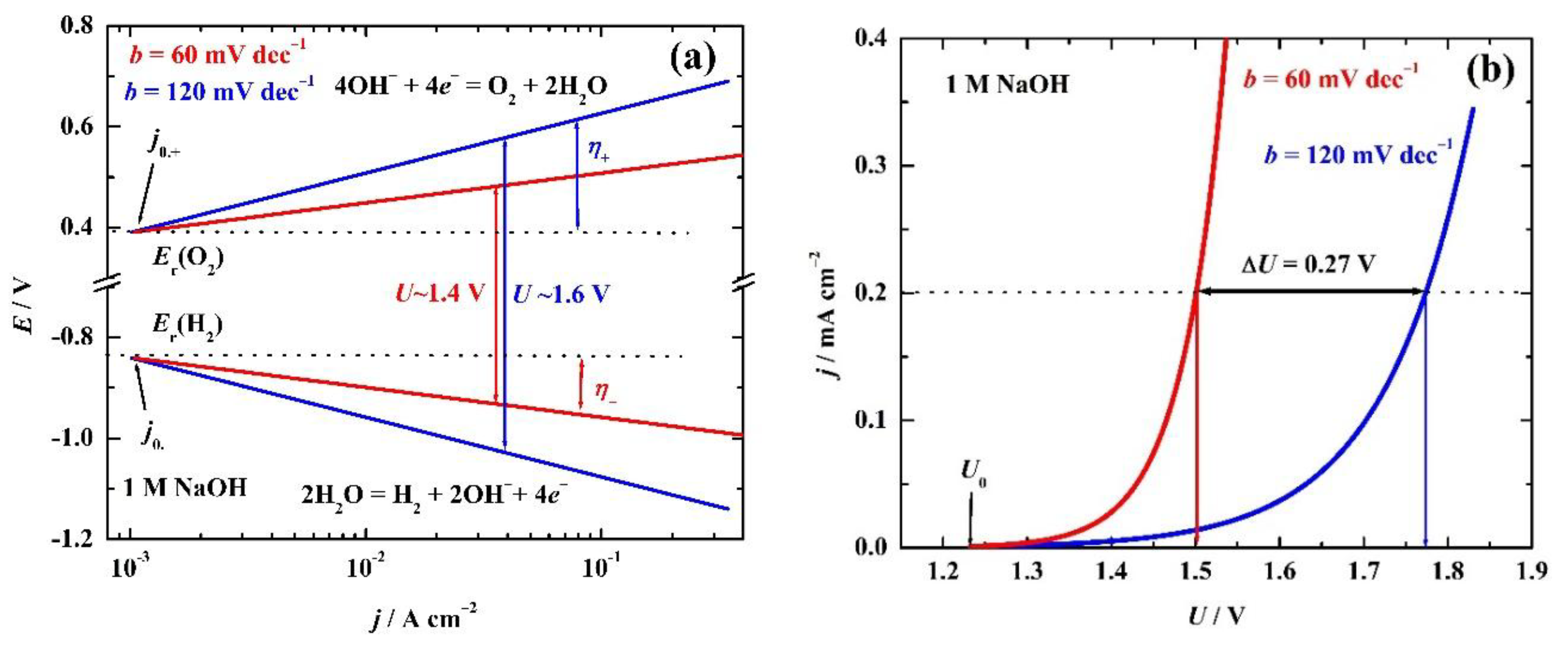
Figure 1. Simulated (a) structure of the potentials, and (b) voltages of alkaline electrolyte electrolysis for two different Tafel slopes.
Preprints 220444 g001
Figure 2. The structure of the LDH catalyst. Reprinted from Kulkarni et al., Nitrogen, 2025, 6, 106 [33] under Creative Commons Attribution (CC BY) license.
Preprints 220444 g002
Figure 3. SEM images of Ni fiber electrode, (a) and NiFe LDHs/Ni fiber electrode (b–d) under different magnification. Reprinted from Guo et al. Energies. 2022; 15(13), 4645. [34] under Creative Commons Attribution (CC BY) license.
Preprints 220444 g003
Figure 4. Simulated (a) stability test, (b) cyclic voltammograms, (c) polarization curves, and (d) electrochemical impedance spectroscopy, Nyquist plot, before and after stability test.
Preprints 220444 g004
Figure 5. The XRD of spinel NiFe2O4. Inset: magnified 331 peak [74].
Preprints 220444 g005
Figure 6. The SEM (a) and (c); and EDS (b) and (d) at 7 keV, of spinel NiFe2O4 before and after stability test at 100 mA cm–2 for 24 h [74].
Preprints 220444 g006
Figure 7. (A) XPS peaks before and after OER of the FeOOH/NiFe-LDH sample; (A, D) Ni 2p; (B, E) Fe 2p; (C, F) O1s. Reproduced from Yu, et al., Nanomaterials 2025,15, 949 [75] under Creative Commons Attribution (CC BY) license.
Preprints 220444 g007
Disclaimer/Publisher’s Note: The statements, opinions and data contained in all publications are solely those of the individual author(s) and contributor(s) and not of MDPI and/or the editor(s). MDPI and/or the editor(s) disclaim responsibility for any injury to people or property resulting from any ideas, methods, instructions or products referred to in the content.
Copyright: This open access article is published under a Creative Commons CC BY 4.0 license, which permit the free download, distribution, and reuse, provided that the author and preprint are cited in any reuse.
Prerpints.org logo

Preprints.org is a free preprint server supported by MDPI in Basel, Switzerland.

Subscribe

© 2026 MDPI (Basel, Switzerland) unless otherwise stated

Accessibility

Disclaimer

Terms of Use

Privacy Policy

Privacy Settings