Submitted:
15 June 2026
Posted:
16 June 2026
You are already at the latest version
Abstract

Keywords:
1. Introduction
- (1) Dependence on physical ECU prototypes and bring-up delays. HIL testing begins only after physical ECU availability, directly coupling verification schedules to prototype delivery. Even after prototype arrival, initialization tasks (boot, memory configuration, flashing, and communication link verification) require substantial manual effort, and hardware-specific issues (e.g., wiring faults or connector problems) further increase delay.
- (2) Non-standardized interfaces and project-specific custom development. HIL must integrate analog/digital I/O for sensor/actuator emulation as well as bus interfaces such as CAN and LIN. Conventional solutions often employ custom fault injection, signal conditioning, and interface hardware tailored to each project, which increases setup and maintenance cost while amplifying the probability of configuration errors.
- (3) High configuration cost for in-vehicle networks and manual mapping. In multi-ECU systems, network traffic must be reproduced faithfully in the test environment. Message and signal definitions (commonly specified via CAN DBC files) are frequently mapped manually to simulator variables and I/O channels. Minor mistakes (e.g., scaling, endianness, cycle time, or identifier mismatches) can cause system-wide integration failure, leading to long debugging cycles and delaying the first executable test.
- 1.
- Configuration-driven generation of FMU-based network interaction nodes. A DBC-driven automation pipeline is introduced to generate FIL Nodes that encapsulate network I/O structures and communication logic as FMI-compliant models, substantially reducing repetitive and error-prone manual mapping tasks in HIL and vHIL setups.
- 2.
- Improved repeatability and scalability of multi-ECU vHIL integration. By automating signal scaling, byte ordering, scheduling attributes, and DBC-to-FMU mapping, the proposed approach minimizes human-induced configuration errors and enables reproducible construction of distributed ECU networks in a virtual environment.
- 3.
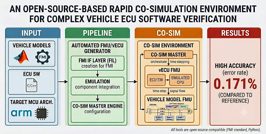
- Reduction of test readiness effort while preserving timing fidelity. By eliminating manual DBC-to-simulator signal mapping, the proposed pipeline removes the dominant recurring configuration steps (identifier assignment, scaling, endianness, and cycle-time setup) that otherwise require per-project manual effort. Experimental validation confirms that the resulting vHIL environment maintains timing behavior equivalent to physical ECU measurements, with a maximum relative error of 0.171% across all evaluated step sizes.
2. Related Work and Technical Background
2.1. Xil Verification Framework and Virtual ECU Technology
2.2. Fmi-Based Co-Simulation and the Renode Platform
3. Design of the FMU-Based Interaction Layer (FIL) Node
4. Auto Generator for FIL Node
4.1. Overview of the Auto Generator Framework
4.2. Dbc Preprocessing and Intermediate Representation
4.3. Node-Level Structuring and Transmission Semantics
4.4. Model Skeleton and Code Generation
4.5. Fmu Export and Deterministic Timing Configuration
5. Experimental Validation
5.1. Validation Objectives and Experimental Scope
5.2. Co-Simulation Environment and Reference Setup
5.3. Network Configuration and Test Scenario
5.4. Measurement Procedure and Reproducibility
5.5. Evaluation Metrics
5.6. Fidelity Results
5.7. Scalability Results
6. Conclusions
Author Contributions
Funding
Abbreviations
| ADAS | Advanced Driver-Assistance Systems |
| ECU | Electronic Control Unit |
| HPC | High-Performance Computing |
| HIL | Hardware-in-the-Loop |
| vHIL | Virtual Hardware-in-the-Loop |
| vECU | Virtual ECU (Virtual Electronic Control Unit) |
| UUT | Unit Under Test |
| CAN | Controller Area Network |
| AUTOSAR | AUTomotive Open System ARchitecture |
| FMI | Functional Mock-up Interface |
| DBC | CAN DataBase (file) |
| IL | Interaction Layer |
References
- Esfandyari, M. J.; Reza, M.; Esfahanian, V.; Nehzati, H. A Low-Cost Single PC Based HiL Simulation Platform for Verification of the Hybrid Electric Vehicle Control Unit. In Proceedings of the Iranian Conference on Electrical Engineering (ICEE), Mashhad, Iran, 2018; pp. 760–765. [Google Scholar] [CrossRef]
- Hanselmann, H. Hardware-in-the-Loop Simulation Testing and Its Integration into a CACSD Toolset. In Proceedings of the IEEE Conference on Computer-Aided Control System Design (CACSD), Dearborn, MI, USA, 1996. [Google Scholar] [CrossRef]
- Mikelsons, L.; Samlaus, R. Towards Virtual Validation of ECU Software Using FMI. Linköping Electron. Conf. Proc. 2017, 132, 307–311. [Google Scholar] [CrossRef]
- Kyung, D.-G.; Joe, I.; Kim, W. An FMI-based Time Management Scheme for Real-time Co-Simulation. J. IKEEE 2020, 24(2), 426–434. [Google Scholar] [CrossRef]
- Junior, J. C. V. S.; Brito, A. V.; Nascimento, T. P. Testing Real-Time Embedded Systems with Hardware-in-the-Loop Simulation Using High Level Architecture. In Proceedings of the Brazilian Symposium on Computing Systems Engineering (SBESC), Foz do Iguaçu, Brazil, 2015; pp. 142–147. [Google Scholar] [CrossRef]
- Mihalič, F.; Truntič, M.; Hren, A. Hardware-in-the-Loop Simulations: A Historical Overview of Engineering Challenges. Electronics 2022, 11(15), 2462. [Google Scholar] [CrossRef]
- Shylla, D.; Jain, A.; Shah, P.; Sekhar, R. Model-in-the-Loop (MIL), Software-in-the-Loop (SIL) and Hardware-in-the-Loop (HIL) Testing in MBD. In Proceedings of the IEEE International Conference on Green Computing and Communication Technologies (GCAT), Bengaluru, India, 2023; pp. 1–6. [Google Scholar] [CrossRef]
- Schlatzer, D.; Schade, N.; Pannek, J. Enabling Credibility for Virtual Testing of Autonomous Vehicles by Adapting DevOps to Hardware-in-the-Loop Simulations. In Proceedings of the IEEE Intelligent Vehicles Symposium (IV), Seoul, Republic of Korea, 2025; pp. 1862–1867. [Google Scholar] [CrossRef]
- Kim, H.; Kwak, J.; Cho, J. AUTOSAR-Compatible Level-4 Virtual ECU for the Verification of the Target Binary for Cloud-Native Development. Electronics 2024, 13(18), 3704. [Google Scholar] [CrossRef]
- Zhong, J.; Jin, Y.; Lian, G.; Ding, G.; Zhu, C. Efficient Control System Development Using Real-Time Virtual Hardware-in-the-Loop Simulation. In Proceedings of the International Conference on Control, Automation, Robotics and Vision (ICARCV), Singapore, 2010; pp. 2231–2236. [Google Scholar] [CrossRef]
- Rani, V. S.; Ramesh, A.; Deepthi, K.; Reddy, V. R. Shift-Left Testing in DevOps: A Study of Benefits, Challenges, and Best Practices. In Proceedings of the IEEE International Conference on Advances in Computing, Communication and Robotics (ICACRS), Tamil Nadu, India, 2023. [Google Scholar] [CrossRef]
- Vaddadi, S. A.; Thatikonda, R.; Padthe, A.; Rao, R. Shift-Left Testing Paradigm Process Implementation for Quality of Software Based on Fuzzy. Soft Computing 2023. [Google Scholar] [CrossRef]
- Jawalkar, S. K. Proactive Software Testing: The Shift-Left Approach to Early Defect Detection and Prevention. Int. J. Multidiscip. Res. 2019, 1(2). [Google Scholar] [CrossRef]
- Bergström, D.; Göransson, R. Model- and Hardware-in-the-Loop Testing in a Model-Based Design Workflow. Student Thesis, Lund University, Lund, Sweden, 2016. [Google Scholar]
- Koppak, R. Multi-Domain Fault Simulation Using Virtual Prototypes. Thesis, Degree-Granting Institution, Location, 2022. [Google Scholar]
- Bunzel, S. AUTOSAR – the Standardized Software Architecture. Informatik-Spektrum 2010, 34(1), 79–83. [Google Scholar] [CrossRef]
- AUTOSAR. Available online: https://www.autosar.org/ (accessed on 14 September 2025).
- Blochwitz, T.; Otter, M.; Åkesson, J.; Arnold, M.; Clauß, C.; Elmqvist, H.; Friedrich, M.; Junghanns, A.; Mauss, J.; Neumerkel, D.; Olsson, H.; Viel, A. Functional Mockup Interface 2.0: The Standard for Tool Independent Exchange of Simulation Models. In Linköping Electronic Conference Proceedings; 2012. [Google Scholar] [CrossRef]
- Blochwitz, T.; Otter, M.; Arnold, M. G.; Bausch, C.; Elmqvist, H.; Junghanns, A.; Mauss, J.; Monteiro, M. S.; Neidhold, T.; Neumerkel, D.; Olsson, H.; Peetz, J.-V.; Wolf, S.; Clauß, C. The Functional Mockup Interface for Tool Independent Exchange of Simulation Models. In Linköping Electronic Conference Proceedings; 2011. [Google Scholar] [CrossRef]
- Renode. Available online: https://www.renode.io/ (accessed on 14 September 2025).


| Test Level | UUT | Environment | Primary Sources |
|---|---|---|---|
| (Unit Under Test) | / Inputs | of Complexity Growth | |
| MIL | Control model (SW) | Simulation | Ensuring model fidelity |
| environment (SW) | |||
| SIL | Control model (SW) | Simulation | Code generation |
| environment (SW) | and integration | ||
| PIL | Target ECU’s MCU binary | Simulation | Compiler/processor integration; |
| environment (SW) | debugging | ||
| vHIL | vECU (target binary) | Simulation | Virtual-hardware fidelity; |
| environment (SW) | deterministic execution | ||
| HIL | Physical ECU (HW/SW) | Real-time | Real-time constraints; |
| simulator (RT HW) | physical I/O; network integration |
| Procedure MasterPipeline(step, dbcFile, jsonFile, fixedStep_us) |
|---|
| 1: set_workspace_var("FixedStep_us", fixedStep_us) |
| 2: // STEP = 0: run all stages, 1/2/3: run only that stage |
| 3: if (step == 0 or step == 1) then |
| 4: // Stage 1: DBC → JSON conversion |
| 5: step1_dbc_to_json(dbcFile, jsonFile) |
| 6: end if |
| 7: if (step == 0 or step == 2) then |
| 8: // Stage 2: JSON → workspace arrays |
| 9: step2_json_to_workspace_can_arrays(jsonFile) |
| 10: end if |
| 11: if (step == 0 or step == 3) then |
| 12: // Stage 3: workspace → FIL Node model/code & FMU export |
| 13: step3_workspace_to_FILNode_generate() |
| 14: end if |
| ECU1 | ECU2 | ECU3 | ECU4 | |
|---|---|---|---|---|
| Cyclic Messages_100ms | 0x100 | 0x103 | 0x104 | 0x105 |
| 0x101 | ||||
| 0x102 | ||||
| Event Messages_triggered Id | 0x200_0x103 | 0x203_0x100 | 0x204_0x101 | 0x205_0x102 |
| 0x201_0x104 | ||||
| 0x202_0x105 |
| Component | Version / Specification |
|---|---|
| Co-simulation master | MasterSim 0.9.x (fixed-step FMI 2.0 CS) |
| vECU platform | Renode 1.14.x |
| FIL Node toolchain | MATLAB/Simulink R2023b + FMI Kit |
| Physical reference | Vector CANoe 16.0, hardware timestamp |
| Host OS | Windows 10 64-bit |
| Host CPU | Intel Core i7-12700, 32 GB RAM |
| Step Size | Avg. Message Interval | Relative Error |
|---|---|---|
| Physical ECU (Reference) | 100.010 ms | — |
| 10 s | 100.096 ms | 0.086% |
| 20 s | 100.138 ms | 0.128% |
| 50 s | 100.167 ms | 0.157% |
| 100 s | 100.181 ms | 0.171% |
| 200 s | 100.181 ms | 0.171% |
| 500 s | 100.177 ms | 0.167% |
| 1000 s | 100.177 ms | 0.167% |
Disclaimer/Publisher’s Note: The statements, opinions and data contained in all publications are solely those of the individual author(s) and contributor(s) and not of MDPI and/or the editor(s). MDPI and/or the editor(s) disclaim responsibility for any injury to people or property resulting from any ideas, methods, instructions or products referred to in the content. |
© 2026 by the authors. Licensee MDPI, Basel, Switzerland. This article is an open access article distributed under the terms and conditions of the Creative Commons Attribution (CC BY) license (http://creativecommons.org/licenses/by/4.0/).