
Preprint
Article

This version is not peer-reviewed.

Rheology-Guided Material Extrusion of Highly Filled SmFeN and SrFe12O19 Magnetic Filaments Using a Polyolefin-Based Binder

Submitted:

11 June 2026

Posted:

12 June 2026

You are already at the latest version

Abstract
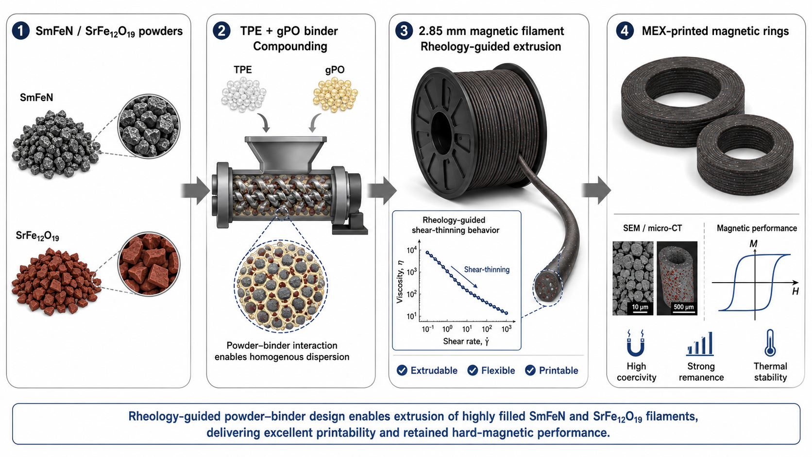
Highly filled magnetic filaments require binder systems that balance powder loading, melt flow, filament strength, and strand stability during material extrusion (MEX). Here, a polyolefin-based binder composed of a thermoplastic elastomer and grafted polyolefin (TPE + gPO) was used to prepare SmFeN- and SrFe12O19-based magnetic filaments. The feedstocks were compounded, extruded into 2.85 mm filaments using a single-screw extrusion line with automatic spooling, and printed by MEX into ring-shaped specimens. Thermogravimetric analysis confirmed high powder contents, with residual masses of approximately 89 wt.% for SmFeN and 85 wt.% for SrFe12O19. The filaments showed good dimensional control, with a diameter of 2.85 ± 0.07 mm and ovality <= 0.017 mm. Small-amplitude oscillatory rheology at 200-240 °C showed pronounced shear-thinning behavior and an elastic-dominant response (G’ > G’’) over 0.01-100 Hz, supporting flow through the nozzle and shape retention after deposition. Mechanical testing confirmed sufficient handling performance, with maximum flexural stress of 36.1 ± 0.1 MPa for SrFe12O19 and flexural modulus up to 5.5 ± 0.2 GPa for SmFeN. The results demonstrate that the TPE + gPO binder provides a suitable processing window for highly filled magnetic filaments for MEX-printed bonded magnets.
Keywords: 
;  ;  ;  ;  ;  ;  ;  ;  

1. Introduction

Polymer-bonded permanent magnets produced by material extrusion (MEX), also known as fused filament fabrication (FFF), offer design freedom, rapid prototyping, and low tooling costs for applications such as motors, sensors, and customized magnetic assemblies [1,2,3,4,5,6]. Several additive manufacturing (AM) routes have been investigated for bonded magnets, including binder jetting [7], stereolithography [8], selective laser sintering [9], direct-write inks [10], and MEX [3]. These techniques differ in achievable solids loading, dimensional accuracy, surface quality, density, and processing throughput [1,2,6,11]. Among them, MEX is particularly attractive because it uses relatively simple equipment and can process highly filled thermoplastic feedstocks into near-net-shape bonded magnets. However, successful MEX printing of magnetic composites requires a careful balance between high powder loading, filament flexibility, melt flow, and strand stability after deposition.
Polymer-bonded magnets are composite materials in which magnetic powders are dispersed in a polymer matrix. Common binder materials include polyamides (PA), polypropylene (PP), polyphenylene sulfide (PPS), thermoplastic polyurethane (TPU), low-density polyethylene (LDPE), and high-density polyethylene (HDPE) [1,2,3,4,5,11,12]. In highly filled MEX feedstocks, the magnetic powder provides the functional magnetic response, whereas the polymer binder controls processability, filament handling, and interlayer bonding during printing [13]. Increasing the filler content is desirable for improving the magnetic powder fraction, but it also increases viscosity and can make filaments brittle or difficult to feed through the printer. Therefore, the binder must provide sufficient flexibility for spooling and feeding, while maintaining adequate stiffness to avoid buckling during printing [14]. Elastomers and polyolefin-based components are often used to improve flexibility and flow behavior in highly filled feedstocks [15,16].
Rheology is a key factor in the processing of highly filled magnetic filaments [17]. During MEX, the feedstock must flow through the nozzle under high shear, but the deposited strand must retain its shape after extrusion. This requires a suitable viscosity profile and viscoelastic response within the printing temperature range. The melt behavior is influenced by powder loading, particle size and morphology, binder composition, powder-binder interactions, temperature, and shear rate. In highly filled systems, particle agglomeration, insufficient binder wetting, or void formation can also affect melt flow, mechanical strength, and the quality of printed parts. For this reason, rheological characterization should be considered together with morphological and mechanical analysis when developing printable magnetic filaments.
In this study, highly filled magnetic filaments based on samarium iron nitride (SmFeN) and strontium ferrite (SrFe12O19) powders were prepared using an in-house polyolefin-based binder composed of a thermoplastic elastomer and grafted polyolefin (TPE + gPO). These two powders were selected to evaluate the processing behavior of compositionally different magnetic fillers within the same binder system. The feedstocks were compounded, extruded into filaments, and printed into ring-shaped specimens using MEX. The powder content was determined by thermogravimetric analysis (TGA), while scanning electron microscopy (SEM) was used to assess powder dispersion, binder coverage, and void formation. Tensile and three-point bending tests were performed to evaluate filament handling and feeding performance, and oscillatory rheology was used to determine the melt behavior over the relevant processing temperature range. The aim of this work is to establish a rheology-guided processing window for highly filled SmFeN- and SrFe12O19-based magnetic filaments and to assess their suitability for MEX-printed bonded magnets.

2. Materials and Methods

2.1. Materials and Preliminary Characterizations

The magnetic powders used in this study were samarium iron nitride powder, Sm2Fe17N3, hereafter denoted as SmFeN (Nichia Corporation, Japan), and strontium ferrite powder, SrFe12O19, hereafter denoted as SFO (OP71, DOWA Electronics Materials Co., Japan). According to the supplier data and particle size measurements, the SmFeN powder had a median particle size D50 of approximately 4.0 µm and a density of 7.2 g/cm3, while the SFO powder had a D50 of approximately 3.1 µm and a density of 5.1 g/cm3. The particle size distribution (PSD) was measured by laser scattering. Powder morphology was examined by scanning electron microscopy (SEM). Representative SEM images and PSD curves are shown in Figure 1a-c.
Both powders consisted mainly of irregular, angular particles with fine particles and larger micrometer-scale fragments. The PSD curves showed particle sizes in the few-micrometer range. SmFeN exhibited a slightly larger D50 and a narrower main distribution, whereas SFO showed a finer overall particle size and a broader distribution with a more pronounced fine-particle fraction. The measured particle size parameters are summarized in Table 1.
Magnetic characterization was performed using two complementary methods. Powders, filaments, and selected printed specimens were measured by vibrating-sample magnetometry (VSM, Lakeshore 7304) to compare the evolution of mass-normalized magnetic properties during processing. The magnetization signal was normalized by the measured sample mass and reported as mass magnetization in emu/g. From the second quadrant of the VSM demagnetization curves, the coercivity, Hc, and remanent magnetization, Mr, were determined. In addition, the final MEX-printed ring specimens were characterized using a permagraph (Steingroever EP2) at room temperature. The permagraph measurements were performed on the complete ring geometry and provided component-level magnetic parameters, including remanent flux density, Br, intrinsic coercivity, HcJ, normal coercivity, HcB, and maximum energy product, (BH)max. The magnetic properties of the starting powders are shown in Figure 2 and summarized in Table 1.
The VSM curves show clear differences between the two powders. SmFeN exhibited a higher remanent magnetization, Mr, of approximately 78 emu/g and a coercivity, Hc, of approximately 1110 kA/m. SFO showed a lower Mr of approximately 36 emu/g and an Hc of approximately 296 kA/m. These values confirm the hard-magnetic character of both powders and provide the reference state for evaluating changes after compounding, filament extrusion, and MEX printing.

2.2. Compounding of Feedstock

A flexible thermoplastic elastomer (TPE; Kraiburg TPE GmbH & Co. KG, Germany) was used as the main binder component, while grafted polyolefin (gPO; BYK Chemie GmbH, Germany) was used as the backbone polymer. Two highly filled magnetic feedstocks were prepared using the same binder system and different magnetic powders, namely SmFeN and SFO. The feedstocks were designed to contain approximately 50 vol.% magnetic powder, corresponding to high powder contents in the range of approximately 85-90 wt.%, depending on the powder density.
The SmFeN-based feedstock, denoted as F1_Sm, contained 89.28 wt.% SmFeN powder, 7.13 wt.% TPE, and 3.59 wt.% gPO. The SFO-based feedstock, denoted as F2_Sr, contained 84.89 wt.% SFO powder, 10.06 wt.% TPE, and 5.05 wt.% gPO. The higher powder weight fraction in the SmFeN feedstock results from the higher density of SmFeN compared with SFO.
Compounding was carried out using an internal mixer equipped with counter-rotating roller rotors (HAAKE Rheomixer R3000p, Thermo Fisher Scientific Inc., USA). The mixing chamber had a volume of 310 cm³, and approximately 80% of the chamber volume was filled to promote efficient mixing. The binder components were added during the first minute of mixing, followed by powder addition after 3 min. The powder was added in four portions at 5 min intervals to allow torque stabilization and improve powder dispersion in the binder matrix. The compounding temperature was 200 °C, and the total kneading time was 45 min. The rotor speed was initially set to 30 rpm and was increased to 60 rpm during the final 20 min of compounding.
After compounding, the feedstock was removed from the mixing chamber and cooled to room temperature. The solidified material was pelletized using a cutting mill (Retsch SM200, Retsch GmbH, Germany) equipped with a 4 mm × 4 mm square-opening sieve. The resulting pellets were approximately 2-3 mm in length and were dried at 50 °C for 24 h before filament extrusion.
Table 2. Composition and compounding parameters of the SmFeN- and SFO-based feedstocks.
Feedstock Filler powder Powder content (vol.%) Powder content (wt.%) TPE (wt.%) gPO (wt.%) Compounding temperature (°C) Speed (rpm)
F1_Sm SmFeN 50 89.28 7.13 3.59 200 30-60
F2_Sr SFO 50 84.89 10.06 5.05 200 30-60

2.3. Feedstock Filament Extrusion

Feedstock filaments were produced using a single-screw extruder (FT-E20T-MP-IS, Dr. Collin GmbH, Germany) equipped with three heating zones. A die with a diameter of 2.85 mm was used to obtain filaments suitable for MEX printing. The extruded filament was transported on a conveyor belt, passed through a haul-off unit, and monitored continuously using a laser diameter-measuring system (Diagnostic Laser 2000, SIKORA AG, Germany). The laser system was used to record filament diameter and ovality during extrusion. An automatic spooling unit was used to collect the filaments continuously, as shown in Figure 3.
The extrusion temperature and haul-off conditions were adjusted for each feedstock to obtain a stable filament diameter. The extrusion parameters and measured filament properties are summarized in Table 3. Both feedstocks were successfully extruded and automatically spooled without filament breakage, indicating sufficient filament strength for handling after extrusion. The measured filament diameters were close to the target value of 2.85 mm, with average diameters of 2.85 ± 0.07 mm for F1_Sm and 2.85 ± 0.05 mm for F2_Sr. The corresponding ovality values were 0.017 ± 0.010 and 0.016 ± 0.009, respectively. A representative diameter measurement for the F1_Sm filament is shown in Figure 4.
Diameter and ovality were observed to be within the optimal range (diameter: 2.85 ± 0.07 mm; ovality: ≤ 0.017 mm) as shown in Figure 4a,b. Figure 4a shows that the SmFeN filament diameter remains highly stable over time, fluctuating slightly around an average of about 2.85 mm. Figure 4b confirms this with a narrow, symmetric distribution centered near 2.85 mm, indicating consistent extrusion quality and tight dimensional control.

2.4. Thermal Characterization and Thermogravimetric Analysis

Thermogravimetric analysis (TGA) was performed on the extruded feedstock filaments to determine the magnetic powder content and evaluate the thermal stability of the binder system. Measurements were carried out using a Mettler Toledo TGA-MS instrument. Samples with masses between 3 and 7 mg were heated from 25 to 600 °C at a heating rate of 10 K min-1 under a nitrogen atmosphere with a gas flow rate of 50 mL min-1. The residual mass after thermal decomposition of the polymer binder was used to estimate the magnetic powder content of each filament.

2.5. Rheological Analysis of Feedstocks

Rheological characterization of the feedstock pellets was performed using an MCR 302 rotational rheometer (Anton Paar, Graz, Austria) equipped with a parallel-plate geometry. Measurements were carried out at 200, 220, and 240 °C under an inert nitrogen atmosphere. A 25 mm diameter plate and a 1 mm measurement gap were used. The feedstock pellets were placed directly on the lower plate and allowed to melt before testing.
Amplitude sweep tests were first performed at a constant frequency of 1 Hz by applying shear stress from 10 Pa to 30 kPa to determine the linear viscoelastic region. Frequency sweep tests were then conducted within the linear viscoelastic region over a frequency range of 100 to 0.01 Hz. Depending on feedstock composition and temperature, the applied shear stress for the frequency sweep was selected between 100 and 1000 Pa. In addition, rotational flow tests were performed using a logarithmic shear-stress ramp from 100 Pa to 10 or 30 kPa. Data points were recorded every 2 s during the flow measurements.

2.6. Morphology and Microstructure Characterization

The morphology and microstructure of the extruded filaments and MEX-printed specimens were examined using scanning electron microscopy (SEM; Apreo 2S, Thermo Fisher Scientific, USA). The SEM was equipped with an Oxford Instruments AZtecLive Ultim Max 100 mm2 silicon drift detector (SDD) for energy-dispersive X-ray spectroscopy (EDS). Prior to analysis, the samples were embedded in resin, polished to expose the cross sections, and carbon-coated to reduce charging during imaging and EDS analysis.
Secondary electron (SE) and backscattered electron (BSE) images were acquired at different magnifications using an accelerating voltage of 20 kV. Imaging was performed at multiple positions across the filaments and printed specimens, including the center and outer regions, to assess particle dispersion, binder distribution, voids, and interfacial quality. Because of the magnetic nature of the samples, additional stigmation correction was required during imaging. EDS spectra and maps were processed using the instrument software, with ZAF correction applied for quantitative analysis.

2.7. Mechanical and Physical Characterization of Filaments

The mechanical behavior of the feedstock filaments was evaluated by three-point bending and tensile testing under standard laboratory conditions (23 °C and 50% relative humidity). Three specimens were tested for each feedstock.
Three-point bending tests were performed on filament specimens with a length of 30 mm and a diameter of 2.85 mm using a rheological testing system (MCR702, Anton Paar, Austria) equipped with a three-point bending fixture, as shown in Figure 5a. The support span was 20 mm, and the force was increased at a rate of 1 N s-1 up to a maximum force of 40 N. The maximum flexural stress, flexural strain, and flexural modulus were determined from the load-deflection curves. The maximum flexural stress was calculated according to Equation (1):
σ m a x = F L π R 3 ( Eq . 1 )
where σmax is the maximum flexural stress, F is the applied force, L is the support span, and R is the filament radius. The flexural modulus, Ef, was calculated using Equation (2):
E f = L 3 m 4 π R 4 ( Eq . 2 )
where m is the slope of the linear region of the load-deflection curve.
Tensile tests were performed on straight filament specimens with a length of 100 mm and a diameter of 2.85 mm using a universal testing machine equipped with a 1 kN load cell, as shown in Figure 5b. The gauge length was 50 mm. The filaments were clamped using wedge grips and tested at a crosshead speed of 10 mm min-1 until rupture. The deformation was analyzed using Istra4D software (version 4.6).

2.8. Fabrication and Magnetic Characterization of MEX-Printed Ring Specimens

The printability of the developed feedstock filaments, F1_Sm and F2_Sr, was evaluated using a MEX printer (HAGE3D, Austria). Ring-shaped specimens with an outer diameter of 33 mm, an inner diameter of 26 mm, and a height of 4.3 mm were fabricated. The models were sliced, and G-code was generated using Simplify3D software (version 4.1.2, Simplify3D, Blue Ash, OH, USA). Printing was performed using a brass HAGE3D nozzle with a diameter of 0.8 mm. The same printing parameters were used for both feedstocks to evaluate their processability within a common MEX processing window.
The build plate consisted of a glass substrate covered with commercially available adhesion tape. The tape surface was mechanically roughened using P500-grade sandpaper to improve first-layer adhesion. The printing parameters used for the fabrication of the ring-shaped specimens are summarized in Table 5.
The magnetic properties of the MEX-printed rings were characterized using both VSM and permagraph measurements. For VSM measurements, a small section was cut from each MEX-printed ring specimen because the complete ring geometry could not be accommodated in the VSM sample holder. VSM measurements were used to compare the printed specimens with the corresponding powders and filaments on a mass-normalized basis. For these measurements, the magnetization was reported as mass magnetization, and the remanent magnetization, Mr, and coercivity, Hc, were determined from the second quadrant of the demagnetization curves. In addition, complete MEX-printed rings were measured using a permagraph at room temperature to evaluate the component-level magnetic performance in the final geometry. The permagraph measurements provided Br, HcB, HcJ, and (BH)max.

2.9. Bulk Density Measurement

The bulk density of the extruded filaments and MEX-printed specimens was determined using a Densitec bulk-density meter (Exelia AG, Switzerland). The measurement was based on Archimedes’ principle using low-viscosity silicone oil as the immersion medium. Before measurement, the specimens were dried at 40 °C for 2 h, weighed in air, and then fully submerged in silicone oil with a density of 0.965 g cm-3 at 23 °C. The bulk density was calculated from the measured mass and buoyancy response. Three independent measurements were performed for each sample, and the relative standard deviation was below 2%.

2.10. X-Ray Computed Microtomography (Micro-CT)

X-ray computed microtomography (micro-CT) was used to characterize the internal morphology of the extruded filaments and MEX-printed ring specimens. Measurements were performed using an EasyTom XL 160 Ultra system (RX Solutions, France) equipped with a nanofocus X-ray source operated in the range of 20-160 kVp, with a maximum power of 32 W, and a 16-bit flat-panel detector.
The ring specimens, with an outer diameter of approximately 33 mm, were fixed to the sample holder and scanned along the rotation axis. The scans were acquired at 140 kVp and approximately 47-48 µA using a 1.5 mm Al filter. A total of 2400 projections were collected over a 360° continuous rotation at 1 fps, with four frames averaged per projection. The effective pixel size was approximately 14 µm.
Both filament types, with a diameter of approximately 2.85 mm, were mounted together with their long axes perpendicular to the rotation stage. A filament section of approximately 11 mm was scanned at 120 kVp and 77 uA. For these scans, 2400 projections were collected over a 360° continuous rotation at 1 fps, with six frames averaged per projection. The effective pixel size was approximately 5.5 µm.
Projection data were reconstructed into axial 16-bit TIFF image stacks using X-ACT software (RX Solutions, France). The reconstructed image stacks were used to assess internal defects, porosity, and filament/ring structural homogeneity. Two-dimensional visualization was performed using Fiji/ImageJ, and three-dimensional renderings were generated using Dragonfly software (Comet Technologies, Canada).

3. Results

3.1. Thermal Properties of Filaments

The thermal stability and residual powder content of the extruded magnetic filaments were evaluated by TGA, as shown in Figure 6. Both filaments remained thermally stable up to approximately 330 °C, with only minor mass loss observed in this temperature range. The main mass loss occurred between approximately 350 and 500 °C and is attributed to thermal decomposition of the polymer binder system. After binder decomposition, the residual mass corresponded to the magnetic powder fraction in the filaments.
The residual mass was approximately 89 wt.% for F1_Sm and 85 wt.% for F2_Sr. These values are close to the targeted high powder loading of 85-90 wt.%, confirming that highly filled feedstock filaments were obtained after compounding and extrusion. The measured bulk densities were 4.25 g cm-3 for F1_Sm and 3.10 g cm-3 for F2_Sr (Table 3). Based on the measured densities and powder densities, these values correspond to estimated magnetic solid contents of approximately 52 vol.% for F1_Sm and 51 vol.% for F2_Sr. Therefore, both feedstocks reached powder contents suitable for highly filled MEX filaments.

3.2. Morphology of Filaments

Cross-sectional SEM images of the extruded filaments are shown in Figure 7a-d. At low magnification, both F1_Sm and F2_Sr exhibited dense, highly filled cross sections without visible macroscopic defects. Both filament cross sections appeared nearly circular and showed uniform diameters (2.85 mm), indicating stable filament formation during extrusion. At higher magnification, however, differences in particle distribution and particle-binder interaction were observed. The F1_Sm filament showed a comparatively uniform SmFeN particle network, with good binder coverage and limited interfacial gaps between particles and the polymer matrix. This morphology suggests effective powder dispersion and binder wetting during compounding and extrusion.
In contrast, the F2_Sr filament showed generally good particle dispersion but less homogeneous binder coverage. Localized microvoids and regions of particle-binder separation were observed, as indicated in Figure 7d. These features may act as local stress concentrators and can influence the mechanical response of the filament, particularly stiffness and deformation behavior.

3.3. CT Measurement on Filaments

Micro-CT analysis was used to evaluate the internal structure of the extruded filaments, as shown in Figure 8. The reconstructed top-view images show clear differences between the two filament types. The SFO-based filament (F2_Sr) contains discrete low-attenuation regions, visible as dark spots, which are consistent with internal voids or pores. These features appear localized within the filament cross section rather than uniformly distributed. In contrast, the SmFeN-based filament (F1_Sm) shows a more homogeneous grayscale contrast, with no large voids visible under the same visualization conditions.
The side-view reconstructions further support these observations. The SFO filament exhibits stronger contrast variations along the filament length, suggesting local density variations and/or internal porosity. The SmFeN filament shows a more uniform attenuation profile along the extrusion direction, indicating more homogeneous packing and structural continuity. The pores observed in the SFO filament were approximately circular and had characteristic sizes of about 30-40 µm. These micro-CT observations are consistent with the SEM results, where localized voids and particle-binder separation were also observed in the SFO-based filament.
The higher structural homogeneity of the SmFeN filament suggests more uniform powder distribution and binder wetting during compounding and extrusion. In contrast, the localized porosity in the SFO filament may reduce the effective load-bearing area and act as stress-concentration sites during mechanical testing. These features are therefore expected to influence filament stiffness, strength, and feeding reliability during MEX processing.

3.4. Mechanical Testing of Feedstock Filaments

Three-point bending and tensile tests were performed to evaluate the mechanical suitability of the extruded feedstock filaments for handling, spooling, and MEX feeding. The representative stress-strain curves are shown in Figure 9a,b, and the calculated mechanical properties are summarized in Table 4.
In three-point bending, both filaments showed continuous deformation without fracture during the test, indicating sufficient flexibility for handling and automatic spooling. The SFO-based filament, F2_Sr, exhibited the higher maximum flexural stress of 36.12 +/- 0.14 MPa, while F1_Sm showed a value of 31.45 +/- 1.77 MPa. In contrast, the SmFeN-based filament, F1_Sm, showed the higher flexural modulus of 5.5 +/- 0.2 GPa, compared with 3.0 +/- 0.04 GPa for F2_Sr. This indicates that F1_Sm was stiffer, whereas F2_Sr tolerated higher flexural stress under the applied test conditions.
The tensile results showed comparable trends. F2_Sr exhibited a slightly higher ultimate tensile strength (UTS) of 12.28 +/- 0.39 MPa, while F1_Sm showed a UTS of 11.40 +/- 0.73 MPa. However, F1_Sm again showed the higher Young’s modulus of 2.1 +/- 0.01 GPa, compared with 1.7 +/- 0.03 GPa for F2_Sr. These values are within the range reported for highly filled feedstock filaments and are suitable for filament handling and feeding during MEX processing [14,16,18,19].
The mechanical trends are consistent with the morphology observed by SEM and micro-CT. The more homogeneous particle-binder network in F1_Sm likely promoted load transfer and increased stiffness. In contrast, the localized voids and less homogeneous binder coverage observed in F2_Sr may have reduced stiffness, although the filament still maintained higher flexural stress and UTS. Overall, both feedstocks produced mechanically stable filaments suitable for MEX printing, while their different mechanical responses reflect the influence of powder type, particle packing, and powder-binder interaction.

3.5. Rheological Properties of Feedstocks

Rheological analysis was performed to evaluate the melt flow behavior and viscoelastic response of the highly filled feedstocks during MEX processing. Figure 10 shows the complex viscosity, η*, as a function of frequency at 200, 220, and 240 °C. Both F1_Sm and F2_Sr exhibited pronounced shear-thinning behavior over the investigated frequency range, with η* decreasing continuously as frequency increased. This behavior is favorable for MEX because the feedstock can flow more easily under the high-shear conditions inside the nozzle, while higher viscosity at lower shear rates can support strand stability after deposition [16].
At all temperatures, F1_Sm showed higher complex viscosity than F2_Sr. This difference indicates stronger particle-particle and/or particle-binder interactions in the SmFeN-based feedstock, consistent with the more homogeneous and continuous particle-binder network observed by SEM and micro-CT. In contrast, the lower viscosity of F2_Sr suggests a less resistant internal network and easier melt flow. Increasing the temperature from 200 to 240 °C reduced the viscosity of both feedstocks, as expected for thermoplastic binder systems, but the relative ranking remained unchanged. This indicates that the powder type strongly influenced the melt response across the investigated processing window.
The viscoelastic properties are shown in Figure 11. For both feedstocks and at all tested temperatures, the storage modulus, G′, was higher than the loss modulus, G″, across the investigated frequency range. This elastic-dominant response indicates the presence of a particle-supported network within the highly filled feedstocks. Such behavior is beneficial for MEX because it can help the extruded strand retain its shape after deposition. The absolute values of G′ and G″ followed the same trend as the complex viscosity, with F1_Sm showing higher moduli than F2_Sr. This confirms that the SmFeN-based feedstock formed a stronger internal network, whereas the SFO-based feedstock showed a lower resistance to deformation. Overall, both feedstocks exhibited shear-thinning behavior and elastic-dominant viscoelasticity, indicating a suitable rheological processing window for MEX printing.

3.6. Magnetic Properties of Feedstock Filaments

The magnetic properties of the extruded filaments are shown in Figure 12 and were compared with those of the corresponding starting powders. After compounding and filament extrusion, both feedstocks showed lower mass-normalized Mr than the starting powders. For F1_Sm, Mr decreased from approximately 78 emu/g for the powder to 62 emu/g for the filament, while Hc decreased from 1110 to 950 kA/m. For F2_Sr, Mr decreased from approximately 36 to 32 emu/g, while Hc decreased from 296 to 278 kA/m.
The reduction in Mr is mainly attributed to dilution by the non-magnetic polymer binder, because the VSM signal was normalized to the total mass of the composite filament rather than only to the magnetic powder mass. Therefore, the lower magnetic powder fraction in the filament directly reduces the measured mass magnetization. In contrast, Hc is not expected to decrease simply because of polymer dilution, since coercivity is primarily governed by the magnetic powder characteristics, including particle size, morphology, surface condition, and domain reversal behavior. The moderate reduction in Hc after processing may therefore be related to changes introduced during compounding and extrusion, such as particle surface modification, minor oxidation, local damage, altered particle-particle interactions, or differences in demagnetizing effects between powders and composite filaments. Overall, the VSM results indicate that the hard-magnetic character of both fillers was largely retained after filament fabrication, with the main change being the expected decrease in mass-normalized Mr due to the binder fraction.

3.7. Additive Manufacturing by MEX

The printability of the highly filled feedstock filaments was evaluated by fabricating ring-shaped specimens using MEX. Both F1_Sm and F2_Sr were successfully printed using the same nozzle diameter and a common set of printing parameters, summarized in Table 5. The printed specimens, denoted as R1_Sm and R2_Sr, are shown in Figure 13. The ability to process both feedstocks under the same printing window indicates that the TPE + gPO binder system provided sufficient melt flow through the nozzle and adequate strand stability after deposition.
Table 5. MEX printing parameters used for the fabrication of ring-shaped specimens.
Printing Parameters Values
Nozzle temperature (°C) 220-230
Bed temperature (°C) 25 °C
Chamber temperature (°C) 55-60
Printing speed (mm/s) 5-11
Layer height (mm) 0.20-0.30
Extrusion multiplier (%) 0.90-1.05
Infill density (%) 100
Infill orientation ±45°
The selected printing parameters were guided by the rheological behavior discussed in Section 3.5. Both feedstocks exhibited shear-thinning behavior, which supports flow under the high-shear conditions inside the nozzle, and elastic-dominant behavior (G′ > G″), which helps the deposited strand retain its shape. The nozzle temperature of 220-230 °C was selected to provide stable extrusion while avoiding excessive softening of the deposited material. A 0.8 mm nozzle was used to reduce the risk of clogging and to support the flow of highly filled feedstocks.
Good first-layer adhesion was achieved using roughened adhesive tape on a glass build plate. The chamber temperature was maintained at 55-60 °C to reduce thermal gradients during printing and support interlayer bonding. This moderate chamber temperature helped maintain dimensional stability while promoting sufficient contact and healing between adjacent deposited strands. Overall, the successful fabrication of dimensionally consistent ring specimens confirms that both highly filled magnetic filaments can be processed by MEX within a shared processing window.

3.8. Characterization of MEX-Printed Rings

The morphology of the MEX-printed ring specimens was examined by SEM, as shown in Figure 14. At low magnification, both R1_Sm and R2_Sr showed dense cross sections with no large macroscopic defects. The raster structure was only weakly visible, indicating good consolidation between deposited strands. At higher magnification, R1_Sm showed a comparatively uniform particle-binder network, with good particle dispersion and limited interfacial gaps. R2_Sr also showed a highly filled structure, although the particle-binder distribution appeared slightly less homogeneous, consistent with the morphology observed in the corresponding filament.
Micro-CT was further used to evaluate the internal structure of the printed rings. The reconstructed images, shown in Figure 15, showed continuous ring geometries for both SFO- and SmFeN-based specimens, with no large internal voids or major structural discontinuities visible at the scanned resolution. Minor local contrast variations were observed near the outer regions of the rings, which may be related to surface roughness, local bead overlap, or small density variations introduced during layer deposition. The arrows in Figure 15 indicate the start/end region of ring deposition, where the lower print-head velocity during path initiation and termination can locally increase material residence and promote additional particle deposition. Overall, the CT results confirm that both feedstocks could be printed into structurally continuous ring specimens using the selected MEX processing window.
The magnetic properties of the printed rings were measured by VSM using small representative sections cut from the rings, as the complete ring geometry could not be mounted in the VSM sample holder. The results are shown in Figure 16 and summarized in Table 6. The printed rings retained the hard-magnetic character of the corresponding filaments. For the SmFeN-based material, Mr decreased slightly from 62 emu/g for F1_Sm to 60 emu/g for R1_Sm, while Hc decreased from 950 to 863 kA/m. For the SFO-based material, Mr decreased from 32 emu/g for F2_Sr to 26 emu/g for R2_Sr, while Hc decreased from 278 to 264 kA/m.
The small reduction in mass-normalized Mr after printing may be associated with processing-related effects such as local density variations, strand deposition history, and possible changes in particle packing during nozzle extrusion. The decrease in Hc was moderate for both materials, indicating that the hard-magnetic behavior was largely preserved after MEX printing. The higher Mr and Hc values of R1_Sm compared with R2_Sr reflect the stronger magnetic response of the SmFeN powder. Overall, the combined SEM, micro-CT, and VSM results show that the selected binder system enabled the fabrication of dense, structurally continuous, and magnetically functional MEX-printed ring specimens.
Permagraph measurements were performed on complete MEX-printed ring specimens to evaluate the component-level magnetic performance, as shown in Figure 17. In contrast to VSM, which measures small samples and reports mass-normalized magnetization, the permagraph measures the whole ring geometry in a closed magnetic circuit and provides engineering magnetic parameters such as Br, HcB, HcJ and (BH)max. The SmFeN-based ring showed Br = 322 mT, and HcJ = 876 kA/m, and (BH)max = 18.8 kJ/m3. The SFO-based ring showed Br = 103 mT, HcB = 73.83 kA/m, HcJ = 272 kA/m, and (BH)max = 1.9 kJ/m3.
These results confirm that both printed rings retained hard-magnetic behavior after MEX processing. The higher Br and (BH)max of the SmFeN-based ring reflect the higher intrinsic magnetization of the SmFeN powder compared with SFO. The permagraph data should therefore be interpreted as the functional magnetic performance of the printed ring geometry, while the VSM data are used to track processing-induced changes from powder to filament and printed specimen.
Table 7. Permagraph-measured magnetic properties of complete MEX-printed ring specimens.
Filler material Density
(g cm-3)
Hcj,
(kA/m)
Br
(mT)
R1_Sm 4.36 876 322
R2_Sr 3.2 272 103

4. Discussion

The results show that powder dispersion, particle-binder interaction, and internal defects strongly influence the mechanical, rheological, and printing behavior of highly filled magnetic filaments for MEX. This agrees with previous work on highly filled extrusion feedstocks, where powder characteristics, binder composition, and powder-binder compatibility were shown to control flow behavior, filament integrity, and printability [13,14,16,19,20,21]. In the present study, the TPE + gPO binder system provided a common processing window for both SmFeN- and SFO-based feedstocks, although the two powders produced different microstructural and flow responses. SEM and micro-CT observations showed that the SmFeN-based filament formed a more homogeneous particle-binder network, whereas the SFO-based filament contained localized voids and less uniform binder coverage. These differences were reflected in the mechanical properties: F1_Sm showed higher flexural and tensile modulus, while F2_Sr showed slightly higher maximum flexural stress and UTS. This confirms that filler morphology, packing, and interfacial quality play a central role in determining the performance of highly filled feedstock filaments.
The rheological results further support this interpretation. Both feedstocks exhibited pronounced shear-thinning behavior, which is beneficial for MEX because it supports flow through the nozzle under high shear while allowing the deposited strand to retain its shape after extrusion. Similar shear-thinning behavior has been reported for highly filled polymer feedstocks and is generally considered favorable for extrusion-based processing [15,16,17,19,22]. At the same time, the storage modulus exceeded the loss modulus over the tested frequency range, indicating an elastic-dominant response associated with a particle-supported internal network. F1_Sm showed consistently higher complex viscosity and higher G′ and G″ values than F2_Sr, suggesting stronger particle-particle and/or particle-binder interactions. In contrast, the lower viscosity and moduli of F2_Sr indicate easier flow but a weaker internal network. The similar temperature-dependent trends from 200 to 240 °C show that both feedstocks remained within a usable processing range, enabling printing with a common nozzle temperature of 220-230 °C and a 0.8 mm nozzle.
The successful fabrication of ring-shaped specimens confirms the practical relevance of the rheological results. Both feedstocks could be printed using the same process window, producing structurally continuous parts with no large internal defects visible by SEM or micro-CT. Previous studies on MEX have shown that stable extrusion and interlayer bonding depend on the combined effects of melt flow, thermal history, contact pressure, and strand stability after deposition [16,17,21,22]. In the present work, the use of a mildly heated chamber likely reduced thermal gradients and supported interlayer contact during deposition, while the selected layer height and printing speed helped maintain dimensional stability. The local material accumulation observed near the start region of the printed rings is consistent with the sensitivity of MEX parts to toolpath transitions, local velocity changes, and transient extrusion behavior during path initiation and termination.
The magnetic measurements showed that the printed specimens retained hard-magnetic behavior after filament extrusion and MEX printing. This is consistent with earlier studies showing that polymer-bonded magnetic materials can preserve their magnetic functionality after additive manufacturing, although the measured magnetic response depends strongly on filler type, filler loading, particle alignment, and processing route [1,4]. Because the VSM data were normalized by total sample mass, the decrease in remanent magnetization, Mr, from powder to filament is mainly attributed to dilution by the non-magnetic binder. The smaller additional decrease from filament to printed ring may be associated with processing-related changes during nozzle extrusion and strand deposition, including local particle rearrangement, density variation, or differences in sample geometry. The observed decrease in Hc from powder to filament to printed ring should be interpreted cautiously, because coercivity is not directly controlled by binder dilution. Instead, it may reflect changes in particle interactions, local surface condition, demagnetizing effects, or processing-induced modifications during compounding and printing. Importantly, both materials preserved their overall hard-magnetic character, with the SmFeN-based specimens showing higher Mr and Hc than the SFO-based specimens.
Overall, this work demonstrates that a TPE + gPO polyolefin-based binder can provide a suitable processing window for highly filled SmFeN and SFO magnetic feedstocks. The binder enabled filament extrusion, automatic spooling, and MEX printing while maintaining sufficient mechanical integrity and favorable rheological behavior. Compared with previous studies on polymer-bonded magnetic filaments and highly filled MEX feedstocks [1,4,17,19,22], the present results highlight the importance of combining rheological analysis with microstructural and magnetic characterization. The results support the broader potential of this binder strategy for highly filled powder-polymer feedstocks, provided that powder morphology, binder wetting, particle-network formation, and rheological response are considered together during formulation and processing.

5. Conclusions

This study demonstrated that a polyolefin-based binder system composed of TPE and gPO can be used to prepare highly filled SmFeN- and SFO-based magnetic filaments for material extrusion. Both feedstocks achieved high magnetic powder contents, with TGA residual masses of approximately 89 wt.% for F1_Sm and 85 wt.% for F2_Sr, corresponding to estimated solid loadings above 50 vol.%. The extruded filaments showed stable dimensional control, with diameters close to 2.85 mm and low ovality, enabling automatic spooling and subsequent MEX processing.
Rheological analysis showed pronounced shear-thinning behavior and an elastic-dominant response, with G′ > G″ over the investigated frequency range. These properties supported flow through the nozzle and strand stability after deposition. Mechanical testing confirmed that both filaments had sufficient strength and stiffness for handling and feeding, with maximum flexural stress up to 36.12 +/- 0.14 MPa for F2_Sr and flexural modulus up to 5.5 +/- 0.2 GPa for F1_Sm. SEM and micro-CT showed that F1_Sm formed a more homogeneous particle-binder network, while F2_Sr contained localized voids and less uniform binder coverage, explaining the observed differences in stiffness, strength, and rheological response.
Both feedstocks were successfully printed into ring-shaped specimens using a common MEX processing window. The printed rings were structurally continuous and retained hard-magnetic behavior after processing. VSM measurements showed that the reduction in mass-normalized remanent magnetization, Mr, was mainly associated with the non-magnetic binder fraction, while the moderate decrease in coercivity, Hc, may be related to processing-induced changes in particle interactions, local surface condition, or sample geometry. Overall, the results confirm that the TPE + gPO binder provides a suitable processing window for highly filled SmFeN and SFO magnetic filaments and supports the fabrication of geometry-flexible bonded magnets by MEX.
Future work should focus on field-assisted deposition or post-print magnetic alignment, further optimization of powder loading and binder composition, and quantitative assessment of magnetic anisotropy, demagnetizing effects, and long-term environmental stability.

Author Contributions

Conceptualization, Muhammad Shahid Arshad, Mahrukh Sadaf, Lidija Slemenik Perše and Kristina Zuzek; methodology, Muhammad Shahid Arshad, Mahrukh Sadaf, Mohor Mihelčič, Bor Arah, Fabian Burkhardt, Ema Zagar and Rožle Repič; investigation, Muhammad Shahid Arshad, Mahrukh Sadaf, Mohor Mihelčič, Bor Arah, Fabian Burkhardt, Ema Zagar and Rožle Repič; data analysis, Muhammad Shahid Arshad, Mahrukh Sadaf, Mohor Mihelčič and Lidija Slemenik Perše; writing-original draft preparation, Muhammad Shahid Arshad; writing-review and editing, all authors; supervision, Spomenka Kobe, Boris Saje, Lidija Slemenik Perše and Kristina Zuzek; project administration, Kristina Zuzek. All authors have read and agreed to the published version of the manuscript.

Funding

This research was funded by the RSF Jozef Stefan Institute, grant number RSF-0069. Funding from Slovenian Research Agency (ARIS), grant numbers L2-70123 and P2-0084.

Data Availability Statement

The data presented in this study are available from the corresponding author upon reasonable request.

Acknowledgments

The authors acknowledge the Slovenian node of E-RIHS (I0-E012) and financial support from the Slovenian Research and Innovation Agency (core funding P2-0273, Infrastructure I0-0032, and equipment co-financed under Paket 21 and 23).

Conflicts of Interest

Author Boris Saje was employed by the company Kolektor Mobility. The remaining authors declare that the research was conducted in the absence of any commercial or financial relationships that could be construed as a potential conflict of interest.

References

  1. Li, L.; Post, B.; Kunc, V.; Elliott, A.M.; Paranthaman, M.P. Additive manufacturing of near-net-shape bonded magnets: Prospects and challenges. Scr. Mater. 2017, 135, 100–4. [Google Scholar] [CrossRef]
  2. Huber, C.; Abert, C.; Bruckner, F.; Pfaff, C.; Kriwet, J.; Groenefeld, M.; et al. Topology optimized and 3D printed polymer-bonded permanent magnets for a predefined external field. J. Appl. Phys. 2017, 122. [Google Scholar] [CrossRef]
  3. Sonnleitner, K.; Huber, C.; Teliban, I.; Kobe, S.; Saje, B.; Kagerbauer, D.; et al. 3D printing of polymer-bonded anisotropic magnets in an external magnetic field and by a modified production process. Appl. Phys. Lett. 2020, 116. [Google Scholar] [CrossRef]
  4. Huber, C.; Cano, S.; Teliban, I.; Schuschnigg, S.; Groenefeld, M.; Suess, D. Polymer-bonded anisotropic SrFe12O19 filaments for fused filament fabrication. J. Appl. Phys. 2020, 127. [Google Scholar] [CrossRef]
  5. Huber, C.; Abert, C.; Bruckner, F.; Groenefeld, M.; Schuschnigg, S.; Teliban, I.; et al. 3D Printing of Polymer-Bonded Rare-Earth Magnets With a Variable Magnetic Compound Fraction for a Predefined Stray Field. Sci. Rep. 2017, 7, 9419. [Google Scholar] [PubMed]
  6. Li, L.; Tirado, A.; Nlebedim, I.C.; Rios, O.; Post, B.; Kunc, V.; et al. Big Area Additive Manufacturing of High Performance Bonded NdFeB Magnets. Sci. Rep. 2016, 6, 36212. [Google Scholar] [PubMed]
  7. Paranthaman, M.P.; Shafer, C.S.; Elliott, A.M.; Siddel, D.H.; McGuire, M.A.; Springfield, R.M.; et al. Binder Jetting: A Novel NdFeB Bonded Magnet Fabrication Process. JOM 2016, 68, 1978–82. [Google Scholar]
  8. Huber, C.; Mitteramskogler, G.; Goertler, M.; Teliban, I.; Groenefeld, M.; Suess, D. Additive Manufactured Polymer-Bonded Isotropic NdFeB Magnets by Stereolithography and Their Comparison to Fused Filament Fabricated and Selective Laser Sintered Magnets. Materials 2020, 13, 1916. [Google Scholar] [CrossRef] [PubMed]
  9. Mapley, M.C.; Tansley, G.; Pauls, J.P.; Gregory, S.D.; Busch, A. Selective laser sintering of bonded anisotropic permanent magnets using an in situ alignment fixture. Rapid Prototyp. J. 2021, 27, 735–40. [Google Scholar] [CrossRef]
  10. Compton, B.G.; Kemp, J.W.; Novikov, T.V.; Pack, R.C.; Nlebedim, C.I.; Duty, C.E.; et al. Direct-write 3D printing of NdFeB bonded magnets. Mater. Manuf. Process. 2018, 33, 109–13. [Google Scholar]
  11. Huber, C.; Abert, C.; Bruckner, F.; Groenefeld, M.; Muthsam, O.; Schuschnigg, S.; et al. 3D print of polymer bonded rare-earth magnets, and 3D magnetic field scanning with an end-user 3D printer. Appl. Phys. Lett. 2016, 109. [Google Scholar]
  12. Geng, J.; Nlebedim, I.C.; Besser, M.F.; Simsek, E.; Ott, R.T. Bulk Combinatorial Synthesis and High Throughput Characterization for Rapid Assessment of Magnetic Materials: Application of Laser Engineered Net Shaping (LENS™). JOM 2016, 68, 1972–7. [Google Scholar] [CrossRef]
  13. Gonzalez-Gutierrez, J.; Cano, S.; Schuschnigg, S.; Kukla, C.; Sapkota, J.; Holzer, C. Additive Manufacturing of Metallic and Ceramic Components by the Material Extrusion of Highly-Filled Polymers: A Review and Future Perspectives. Materials 2018, 11, 840. [Google Scholar] [CrossRef] [PubMed]
  14. Santos, C.; Gatões, D.; Cerejo, F.; Vieira, M.T. Influence of Metallic Powder Characteristics on Extruded Feedstock Performance for Indirect Additive Manufacturing. Materials 2021, 14, 7136. [Google Scholar] [CrossRef] [PubMed]
  15. Sadaf, M.; Cano, S.; Bragaglia, M.; Schuschnigg, S.; Kukla, C.; Holzer, C.; et al. Comparative analysis of binder systems in copper feedstocks for metal extrusion additive manufacturing and metal injection moulding. J. Mater. Res. Technol. 2024, 29, 4433–44. [Google Scholar] [CrossRef]
  16. Sadaf, M.; Cano, S.; Gonzalez-Gutierrez, J.; Bragaglia, M.; Schuschnigg, S.; Kukla, C.; et al. Influence of Binder Composition and Material Extrusion (MEX) Parameters on the 3D Printing of Highly Filled Copper Feedstocks. Polymers 2022, 14, 4962. [Google Scholar] [CrossRef] [PubMed]
  17. Kim, S.H.; Kim, S.J.; Park, S.J.; Mun, J.H.; Kang, T.G.; Park, J.M. Rheological behavior of magnetic powder mixtures for magnetic PIM. Korea-Aust. Rheol. J. 2012, 24, 121–7. [Google Scholar] [CrossRef]
  18. Chinnakorn, A.; Parsompech, N.; Suwanpreecha, C.; Suwannak, P.; Singkronart, K.; Schuschnigg, S.; et al. Evaluation of polymeric binders in 316L stainless steel manufacturing by filament-based MEX. Prog. Addit. Manuf. 2025, 10, 8345–66. [Google Scholar] [CrossRef]
  19. Cerejo, F.; Gatões, D.; Vieira, M.T. Optimization of metallic powder filaments for additive manufacturing extrusion (MEX). Int. J. Adv. Manuf. Tech. 2021, 115, 2449–64. [Google Scholar] [CrossRef]
  20. Sadaf, M.; Bragaglia, M.; Nanni, F. A simple route for additive manufacturing of 316L stainless steel via Fused Filament Fabrication. J. Manuf. Process. 2021, 67, 141–50. [Google Scholar] [CrossRef]
  21. Sadaf, M.; Bragaglia, M.; Slemenik Perše, L.; Nanni, F. Advancements in Metal Additive Manufacturing: A Comprehensive Review of Material Extrusion with Highly Filled Polymers. J. Manuf. Mater. process. 2024, 8, 14. [Google Scholar] [CrossRef]
  22. Arrigo, R.; Frache, A. FDM Printability of PLA Based-Materials: The Key Role of the Rheological Behavior. Polymers 2022, 14, 1754. [Google Scholar] [CrossRef] [PubMed]
Figure 1. SEM images of the starting magnetic powders: (a) SmFeN and (b) SrFe12O19/SFO. (c) Particle size distributions of SmFeN and SrFe12O19 measured by laser scattering.
Preprints 218094 g001
Figure 2. Second-quadrant VSM demagnetization curves of the starting SmFeN and SFO powders. Magnetization is reported as mass magnetization normalized by sample mass.
Preprints 218094 g002
Figure 3. Filament extrusion and collection: (a) extruded F1_Sm feedstock filament transported on the conveyor belt after exiting the die and (b) automatically spooled feedstock filaments.
Preprints 218094 g003
Figure 4. Representative online diameter measurement of the F1_Sm filament: (a) diameter variation during extrusion and (b) histogram of filament diameter distribution.
Preprints 218094 g004
Figure 5. Experimental setups used for mechanical testing of feedstock filaments: (a) three-point bending test and (b) tensile test.
Preprints 218094 g005
Figure 6. TGA curves of the extruded magnetic filaments F1_Sm and F2_Sr measured under nitrogen atmosphere.
Preprints 218094 g006
Figure 7. Cross-sectional SEM images of extruded feedstock filaments: (a,b) F1_Sm and (c,d) F2_Sr. Low-magnification images show the overall filament cross section, while high-magnification images show particle dispersion and particle-binder interaction. In (d), the yellow circle indicates local particle-binder separation, and the red circles indicate microvoids.
Preprints 218094 g007
Figure 8. Micro-CT reconstructions of the extruded filaments: (a) top view of the SFO-based filament showing localized internal voids, (b) top view of the SmFeN-based filament showing a comparatively uniform cross section, (c) side-view comparison of the SFO and SmFeN filaments, and (d) schematic representation of the top-view and side-view orientations.
Preprints 218094 g008
Figure 9. Stress-strain curves of the extruded feedstock filaments F1_Sm and F2_Sr: (a) three-point bending test using a 40 N load cell and (b) tensile test using a 1 kN load cell.
Preprints 218094 g009
Figure 10. Complex viscosity, η*, as a function of frequency for F1_Sm and F2_Sr at: (a) 200 °C, (b) 220 °C, and (c) 240 °C.
Preprints 218094 g010
Figure 11. Storage modulus, G′, and loss modulus, G″, as a function of frequency for F1_Sm and F2_Sr at: (a) 200 °C, (b) 220 °C, and (c) 240 °C.
Preprints 218094 g011
Figure 12. Second-quadrant VSM demagnetization curves of the extruded feedstock filaments F1_Sm and F2_Sr. Magnetization is reported as mass magnetization normalized by total filament mass.
Preprints 218094 g012
Figure 13. Geometry and photographs of MEX-printed ring specimens. Top: schematic of the ring geometry with nominal dimensions. Bottom: as-printed ring specimens produced from SmFeN-based filament (R1_Sm) and SFO-based filament (R2_Sr); coin shown for scale.
Preprints 218094 g013
Figure 14. SEM micrographs of MEX-printed ring specimens: (a,b) R1_Sm and (c,d) R2_Sr. Low-magnification images show the printed ring cross sections, while high-magnification images show particle dispersion and particle-binder interaction.
Preprints 218094 g014
Figure 15. Micro-CT reconstructions of MEX-printed ring-shaped magnets: (a) R1_Sm and (b) R2_Sr. The arrows indicate the deposition start/end region, where local material accumulation is observed.
Preprints 218094 g015
Figure 16. Second-quadrant VSM demagnetization curves of MEX-printed ring specimens R1_Sm and R2_Sr. Magnetization is reported as mass magnetization normalized by sample mass.
Preprints 218094 g016
Figure 17. Permagraph demagnetization curves of complete MEX-printed ring-shaped magnets R1_Sm and R2_Sr.
Preprints 218094 g017
Table 1. Particle size distribution, density, and magnetic properties of the starting magnetic powders.
Filler material Particle size distribution Density
(g/cm3)
Coercivity, Hc (kA/m) Remanent magnetization, Mr (emu/g)
D10 (µm) D50 (µm) D90 (µm) D90/D10 ratio (µm)
SmFeN 2.05 4.04 8.01 4.39 7.2 1110 78
SFO 1.28 3.12 6.56 5.11 5.1 296 36
Table 3. Filament extrusion parameters and measured filament properties.
Filaments Extrusion Temp.
(°C)
Die Temperature
(°C)
Screw Speed
(rpm)
Diameter
(mm)
Ovality (mm) Density
(g/cm3)
F1_Sm 180-190 190 54 2.85±0.07 0.017±0.01 4.25
F2_Sr 160-170 170 54 2.85±0.05 0.016±0.009 3.10
Table 4. Mechanical properties of the extruded feedstock filaments F1_Sm and F2_Sr.
Bending properties Tensile properties
Material Maximum flexural stress (MPa) Flexural modulus (GPa) UTS (MPa) Young modulus (GPa)
F1_Sm 31.45 ± 1.77 5.5 ± 0.2 11.40 ± 0.73 2.1 ± 0.01
F2_Sr 36.12 ± 0.14 3.0 ± 0.04 12.28 ± 0.39 1.7 ± 0.03
Table 6. Density and VSM-derived magnetic properties of extruded filaments and MEX-printed ring specimens.
Filler material Density
(g cm-3)
Coercivity
(kA/m)
Remanent magnetization, Mr (emu/g)
F1_Sm
R1_Sm
4.27
4.36
950
863
62
60
F2_Sr
R2_Sr
3.1
3.2
278
264
32
26
Disclaimer/Publisher’s Note: The statements, opinions and data contained in all publications are solely those of the individual author(s) and contributor(s) and not of MDPI and/or the editor(s). MDPI and/or the editor(s) disclaim responsibility for any injury to people or property resulting from any ideas, methods, instructions or products referred to in the content.
Copyright: This open access article is published under a Creative Commons CC BY 4.0 license, which permit the free download, distribution, and reuse, provided that the author and preprint are cited in any reuse.
Prerpints.org logo

Preprints.org is a free preprint server supported by MDPI in Basel, Switzerland.

Subscribe

© 2026 MDPI (Basel, Switzerland) unless otherwise stated

Accessibility

Disclaimer

Terms of Use

Privacy Policy

Privacy Settings