

Submitted:
08 June 2026
Posted:
09 June 2026
You are already at the latest version
Abstract
This case study numerically investigates PCM composite integration into attic building envelopes on indoor thermal stability during summer. Attic spaces are particularly vulnerable to overheating due to lightweight construction and intense solar radiation on the roof envelope. Simulations were performed in DesignBuilder using the EnergyPlus engine on a model validated by in-situ measurements (MBE -0.07 °C, CV(RMSE) 4.34 %). Three integration variants of an organic paraffin PCM composite with aluminum encapsulation were defined: ceiling, sloping roof, and floor under the roof window, at thicknesses of 20 and 40 mm with a melting temperature of 28 °C (Rubitherm RT28HC) selected based on measured indoor temperatures. Results demonstrated that the integration position is the decisive factor governing effectiveness. Floor integration yielded the most favorable results due to direct solar radiation exposure, reducing time exceeding 30 °C by 63 % at 20 mm thickness. Increasing thickness to 40 mm brought substantial improvement for the floor variant (from 1.11 °C to 4.85 °C reduction in maximum operative temperature), while the benefit for ceiling and roof variants was marginal. These findings confirm that targeted floor-level PCM composite placement constitutes an effective passive strategy for reducing summer attic overheating and improving indoor thermal comfort in attic spaces.
Keywords:
phase change material
; attic space
; summer overheating
; thermal comfort
; numerical simulation
; DesignBuilder
1. Introduction
The building sector accounts for approximately 40% of global final energy consumption and roughly one-third of global CO₂ emissions, with space cooling representing a growing share driven by climate change and rising thermal comfort expectations [1,2]. In the European Union, buildings consume about 40% of total energy and contribute 36% of energy-related greenhouse gas emissions, making the decarbonization of the building stock a central pillar of the European Green Deal and the Energy Roadmap 2050 [3]. Within this context, the United Nations Sustainable Development Goals (SDGs) explicitly target energy efficiency in buildings through SDG 7 (Affordable and Clean Energy) and sustainable urban development through SDG 11 (Sustainable Cities and Communities), while SDG 13 (Climate Action) underscores the urgency of adaptive measures in the built environment [4].
1.1. Literature Review
Projected climate scenarios indicate that cooling energy demand in temperate climates could increase substantially by 2050 relative to current levels [5], while heating demand could decrease significantly, underscoring the growing importance of passive cooling strategies. Current research documents a performance gap, where measured cooling demand substantially exceeds design predictions, particularly in lightweight buildings with limited thermal mass [6]. Alrasheed and Mourshed [7] identified external solar shading as the most effective passive strategy for insulated dwellings in their critical review, emphasizing that a combination of multiple passive measures is necessary to minimize overheating risk under future climate scenarios. Within the European building stock, attic spaces represent a critically vulnerable typology, as they are exposed to intense solar radiation on the roof envelope and typically feature lightweight construction with low thermal inertia, making them prone to rapid temperature escalation during summer months [8,9].
Phase change materials (PCMs) have emerged as one of the most promising passive solutions for improving the thermal performance of building envelopes over the past decade. PCMs exploit the latent heat of fusion to absorb thermal energy during phase transition, thereby stabilizing indoor temperatures and reducing peak thermal loads [10,11]. Sawadogo et al. [12] confirmed in their review of experimental and numerical studies that PCM integration can reduce peak temperatures and smooth thermal loads, identifying fatty acids and natural insulators as key materials for shape-stabilized PCM composites. Unlike sensible heat storage, which depends on temperature change and material mass, latent heat storage using PCMs offers high energy density within a narrow temperature range, making them particularly suitable for building applications where temperature stability is the primary objective [11].
The scientific literature on PCM integration in buildings has expanded rapidly over the past decade. Several comprehensive reviews have established the key parameters governing PCM effectiveness in building envelopes, including melting temperature, latent heat capacity, thermal conductivity, layer thickness, and position within the construction assembly [10,11,13,14]. Rahman et al. [14] highlighted factors such as melting temperature, thickness, position, volumetric change, and climate conditions as critical determinants of PCM-integrated building thermal performance. Alassaad et al. [10] reported that properly optimized PCM integration can reduce heat transfer across building envelopes by up to 47.6%, stabilize indoor temperature fluctuations by up to 46%, and decrease heating and cooling energy demand by as much as 31%, depending on placement and climate conditions.
Specific simulation and experimental studies provide quantitative evidence of PCM performance across diverse building typologies and climate zones. Zavrl et al. [15] evaluated 14 PCM variants in a lightweight family house in a temperate climate and confirmed that melting point and encapsulation method are the decisive parameters for effectiveness. Mettrick and Ma [16] conducted a global simulation study covering multiple climate zones and found that PCM integration leads to significant reductions in both heating and cooling demand, with melting temperature and layer thickness identified as the most influential factors. Kosny et al. [13] experimentally analyzed the dynamic thermal performance of PCM products and demonstrated that PCM technologies can effectively control both the magnitude and timing of peak thermal loads, thereby shifting cooling demand to off-peak periods. Prajapati et al. [17] demonstrated in a numerical study that integrating a 1.5 cm layer of PCM OM30 into a roof assembly can reduce maximum ceiling temperature by 3.55°C for brick-concrete roofs, up to 8°C for concrete roofs, and up to 13.8°C for metal roofs, with PCM effectiveness increasing as roof thermal inertia decreases.
Hepple et al. [18] showed through numerical simulation that PCM-integrated walls in UK residential buildings improve indoor thermal stability, with the effect being most pronounced in lightweight construction. Saffari et al. [19] demonstrated that combining PCM with controlled natural ventilation in office buildings in temperate climates yields cooling energy savings of 8-15%, with natural ventilation increasing PCM efficiency by an additional 8%. Abdel-Rahman et al. [20] demonstrated in an experimental and simulation study that PCM in double glazing units in Egyptian office buildings reduces yearly cooling electricity consumption by 8.07-8.91% depending on climate region. Ghamari et al. [21] reported that PCM-integrated walls can delay heat transfer by up to 2 hours and that windows equipped with PCM panels reduce heat transfer by up to 66%.
Al-Dalal et al. [22] simulated office buildings in Kurdistan using DesignBuilder and found that PCM reduces cooling energy consumption by approximately 1%, analyzing the effects of location, climate change, and construction parameters. Yemenici and Ekiz Barış [23] demonstrated that the combined use of PCM and thermal insulation in building envelopes can achieve energy savings of 9.12-19.95% when properly selected according to local climatic conditions, with an optimal PCM melting temperature of 27 °C. Naser and Hammadi [24] simulated the effect of PCM on the cooling load of a residential unit in Basrah and found that installing PCM on the outer surface of walls and roofs achieved the highest reduction in cooling load of approximately 18%.
Recent optimization studies have expanded the evidence base from purely technical performance to include economic and environmental dimensions. Young et al. [25] applied multi-objective optimization to PCM-enhanced envelopes in tropical Indonesia and demonstrated achievable reductions in total energy consumption of up to 47.8% and CO₂ emission reductions of up to 52.96%, with optimal melting temperatures in the 23-29 °C range. Jaradat et al. [26] simulated PCM integration in a residential building across multiple climates and reported annual energy savings of 5476.14 kWh, a reduction in greenhouse gas emissions of 2382.31 kg CO₂ eq, and an estimated payback period of four years for external wall applications. Al-Absi et al. [27] demonstrated that PCM retrofitting in tropical buildings can increase thermal comfort time to 98% of occupied hours, directly contributing to reduced mechanical cooling dependence and associated carbon emissions.
Despite the extensive body of research on PCM integration in walls and roofs, systematic investigations of PCM placement within attic spaces with roof window geometry remain scarce. Attic rooms present a unique thermal exposure profile characterized by high solar gains through the roof envelope, a glazed roof window, and typically lightweight construction with low thermal mass. Most existing studies treat the building envelope as a uniform assembly, whereas the differential thermal exposure of individual constructions within a single attic space (ceiling, sloping roof, and floor) has not been systematically compared in terms of PCM effectiveness.
This case study addresses this gap by numerically evaluating the effect of PCM placement (ceiling, sloping roof, floor) and PCM layer thickness (20 mm and 40 mm) on the thermal stability of an attic room, using a validated DesignBuilder/EnergyPlus model. The study aims to identify the optimal PCM configuration for attic overheating mitigation and provide design recommendations applicable to the Central European climatic context.
2. Materials and Methods
The numerical study was conducted using DesignBuilder software with the EnergyPlus calculation engine on a model of a reference attic room. Input parameters were determined based on room geometry, building construction composition, and boundary conditions defined by measured meteorological data. An organic paraffin PCM composite with aluminum macro-encapsulation was selected for the simulation, with the material pair chosen based on chemical compatibility and long-term stability verified in the literature. Based on the differential thermal load of individual attic surfaces, three PCM integration variants were defined, each at two layer thicknesses, in order to evaluate the effect of both placement and PCM quantity on indoor thermal stability.
2.1. Aim of Research
The subject of the dissertation is a comprehensive solution for the integration of phase change materials into building structures, from the selection of a suitable material pair (metal shell + PCM) through experimental verification of its long-term compatibility to numerical optimization of the installation in a specific type of space. The work focuses on attic rooms, which are the most exposed part of buildings in terms of summer overheating.
The main objective of the contribution is to reduce overheating of buildings in the summer months and achieve optimal indoor comfort using phase change materials (PCM), thereby increasing the energy efficiency of buildings. To achieve the main objective, the following sub-objectives are formulated:
• O1: To develop a comprehensive theoretical overview of the issues of building envelopes, solar heat gains, daylighting, building overheating and phase change materials with a focus on their classification, properties and integration possibilities into building structures.
• O2: To experimentally verify the compatibility of selected metal encapsulation materials (aluminum, copper, brass) with selected PCMs through planned interval corrosion tests (PIT) under controlled temperature cycling and to identify the most suitable material pair for further processing and numerical optimization.
• O3: Numerically assess the impact of the installation position of the selected PCM composite (horizontal part of the ceiling, sloping part of the ceiling, floor area under the skylight) on the thermal stability of the indoor environment and identify the optimal integration option.
• O4: Formulate technical recommendations for the integration of PCM composites into building structures with the aim of reducing summer overheating and improving the thermal stability of the indoor environment.
| COMPREHENSIVE THEORETICAL OVERVIEW OF THE ISSUES OF BUILDING EN-VELOPES, SOLAR HEAT GAINS, DAYLIGHTING, BUILDING OVERHEATING AND PHASE CHANGE MATERIALS WITH A FOCUS ON THEIR CLASSIFICATION, PROPERTIES AND INTEGRATION POSSIBILITIES INTO BUILDING STRUCTURES | ||
| EXPERIMENTALLY VERIFY THE COMPATIBILITY OF ALUMINUM, | EXPERIMENTALLY VERIFY THE COMPATIBILITY OF COPPER, | EXPERIMENTALLY VERIFY THE COMPATIBILITY OF BRASS |
| NUMERICALLY ASSESS THE IMPACT OF THE INSTALLATION POSITION OF THE SELECTED PCM COMPOSITE | ||
| HORIZONTAL PART OF THE CEILING, | SLOPING PART OF THE CEILING, | FLOOR AREA UNDER THE SKYLIGHT |
| FORMULATE TECHNICAL RECOMMENDATIONS FOR THE INTEGRATION OF PCM COMPOSITES INTO BUILDING STRUCTURES WITH THE AIM OF REDUCING SUMMER OVERHEATING | ||
2.2. Reference Room
The reference case for the numerical simulation is a test room located at the Institute of Building Structures, Faculty of Civil Engineering, Brno University of Technology, in the attic space of Building D. This is a dedicated research room with no real occupancy, built specifically for comparative measurements of indoor hygrothermal parameters. The room is oriented southwest, with a clear width of 2.8 m, length of 5.3 m, and clear height of 2.3 m. The floor area is 14.84 m² and the indoor air volume is 29.2 m³. The building construction composition is: gypsum board 25 mm + mineral wool insulation 200 mm + gypsum board 25 mm. A roof window is installed in the sloping section of the roof structure. The room was simulated exclusively in passive mode without active heating, cooling, or mechanical ventilation, with natural air infiltration of 1.5 h⁻¹ and no internal heat gains from occupants, lighting, or equipment. The geometric layout of the reference room is illustrated in Figure 1. The basic geometric and operational characteristics of the reference room are summarized in Table 1.
2.3. PCM Composite
The selection of the PCM-encapsulation material pair is a critical factor that directly affects the long-term reliability and service life of the thermal storage system. For this simulation study, an organic paraffin-based PCM combined with aluminum macro-encapsulation was selected.
Organic paraffin PCMs are widely regarded in the literature as the most suitable for building applications due to their chemical stability, minimal supercooling, absence of phase segregation, and high resistance to degradation during repeated melting-solidification cycles [27]. Vakhshouri [27] states that unlike inorganic PCMs (salt hydrates), paraffins do not exhibit corrosive effects on metallic encapsulation, and their latent heat remains stable even after hundreds of thermal cycles. Al-Yasiri and Szabó [28] confirmed in their review that paraffin PCMs incorporated into building envelopes can remarkably improve thermal performance in terms of thermal load reduction, energy savings, and thermal comfort, with poor thermal conductivity remaining the main practical limitation that can be addressed through nanoparticle dispersion, expanded graphite, metal foam, or extended surface techniques. Among organic PCMs, paraffin was preferred over fatty acids and esters due to its broader commercial availability, lower cost, and long-term stability verified in building applications [27].
Aluminum was chosen as the encapsulation material because it satisfies three key requirements: high thermal conductivity (237 W/(m·K)) for effective heat transfer into the PCM, mechanical strength, and excellent chemical compatibility with organic PCMs. Ostry et al. [29], in a systematic compatibility study of PCMs and metals, demonstrated that aluminum exhibits the lowest corrosion rate and minimal surface changes when in contact with organic PCMs among all tested metals (steel, copper, brass). Devanuri et al. [30] subjected a paraffin-aluminum pair to 1500 thermal cycles and confirmed that the change in latent heat after cycling did not exceed 2.9%, while the melting temperature shifted by a maximum of 1.6 °C, indicating high long-term material stability. The aluminum macro-encapsulation effectively compensates for the low thermal conductivity of paraffin (0.2 W/(m·K)) by ensuring uniform heat transfer across the entire PCM layer [28]. Macro-encapsulation was selected as the structurally simplest and most mechanically reliable solution for integration into building panels [28].
Material compatibility between the PCM and its encapsulation is a fundamental prerequisite for system durability. Any chemical interaction (corrosion, diffusion, chemical reaction) leads to progressive degradation of the encapsulation, PCM leakage, material contamination, and ultimately failure of the thermal storage function [29,30].
The parameters of the selected PCM correspond to the commercially available product Rubitherm RT28HC, with a melting temperature of 28 °C (range 27-29 °C) and latent heat of 250 kJ/kg [31]. The melting temperature of 28 °C was chosen based on an analysis of measured operative temperatures in the reference room during the summer period (June-September 2025), which regularly exceeded 28 °C, ensuring that phase change activation occurs during peak thermal load. This value is consistent with the optimal range of 22-28 °C for temperate climates reported by Alassaad et al. [10] and with the finding of Kitsopoulou et al. [39], who identified 28 °C as the most suitable melting temperature for roof-integrated PCM systems.
A conservative latent heat value of 200 kJ/kg was adopted in the simulation to account for potential material degradation during in-service thermal cycling, the effect of the aluminum enclosure on the effective volumetric latent capacity of the composite, and the uncertainties associated with transferring laboratory values to real construction conditions. This conservative approach is commonly employed in simulation studies [37]: if the model demonstrates effectiveness at a reduced latent heat value, the actual performance at full material capacity will be at least comparable. The aluminum encapsulation (1 mm thickness), in addition to chemical compatibility, provides mechanical protection and dimensional stability to the PCM panel.
2.4. Integration Variants
Based on the geometry of the attic space and the differential thermal exposure of individual building constructions within the room, three PCM composite integration variants were defined (Table 3).
The study aims to identify the optimal PCM integration position, not to maximize the quantity of material used. All three variants have deliberately comparable surface areas (7.12–7.48 m²), so the comparison reflects the effect of PCM placement rather than the amount of material. The three variants represent the fundamental structural elements of the attic space with distinct thermal exposure: the horizontal ceiling, the sloping roof, and the floor area below the roof window exposed to direct solar radiation.
The selection of locations draws on the findings of Vucicevic et al. [33], who demonstrated a significant impact of PCM integration on indoor temperature in residential buildings, and Campbell [34], who established the effectiveness of PCM in passive houses with glazed surfaces.
In all three variants, the PCM composite is placed on the interior side of the construction as flat panels with aluminum macro-encapsulation (1 mm thickness). The individual variants represent different thermal load mechanisms:
V1 (ceiling, 7.48 m²) is activated by secondary heat flux from the interior,
V2 (sloping roof, 7.12 m²) by direct heat transmission through the roof assembly, and
V3 (floor below the roof window, 7.40 m²) by direct solar radiation, representing the highest radiative load. V3 covers exclusively the floor area below the roof window, which is directly illuminated by sunlight; the remaining floor area is not covered.
A PCM layer thickness of 20 mm was selected based on a literature review, as this thickness is commonly employed in simulation and experimental studies [10,16] and represents a compromise between latent capacity and construction feasibility. A schematic arrangement of the proposed variants is shown in Figure 2.
2.5. Simulation Model
The numerical model was developed in DesignBuilder 2025.1.1 with the EnergyPlus 23.1 calculation engine [36]. Climatic boundary conditions were defined using measured meteorological data from the weather station at the Faculty of Civil Engineering, Brno University of Technology (FAST BUT) in Brno for the period 1 June 2025 to 30 September 2025, processed into EPW format. Summary meteorological indicators (average outdoor air temperature, maximum and minimum outdoor air temperature, and maximum global solar radiation for each month) are presented in Table 4. Simulations were performed in passive mode with an hourly output interval [36].
Model validation was carried out by comparing the simulated operative temperature with the mean globe thermometer values from in-situ measurements. The globe thermometer was positioned at the center of the reference room during the measurement period. Statistical indicators were evaluated in accordance with ASHRAE Guideline 14, with acceptance criteria of MBE ≤ +/-10 % and CV(RMSE) ≤ 30 % [37].
3. Results
This section presents the numerical simulation results for the three PCM composite integration variants in the attic space. The simulations were performed in passive mode during the summer period (June–September 2025). The results are evaluated based on the maximum operative temperature (OpT_max), daily mean temperature profiles, and the number of hours exceeding threshold temperatures of 26, 28, and 30 °C. First, the accuracy of the numerical model is verified by comparison with in-situ measurements, then the effect of PCM integration position at 20 mm thickness is analyzed, and finally the impact of increasing the PCM layer thickness to 40 mm at the optimal position is evaluated.
3.1. Model Validation
The numerical model validation demonstrated very good agreement with the measured data. For the reference room, the mean bias error (MBE) reached -0.07 °C (-0.24 %) and the coefficient of variation of RMSE (CV(RMSE)) was 4.34 %, both well within the ASHRAE Guideline 14 acceptance criteria [37].
Figure 3 compares daily mean operative temperatures from in-situ globe thermometer measurements with simulated values over the entire monitoring period (June–September 2025). The simulated profile closely follows the measured values across all phases of the measurement campaign, including summer temperature peaks, transitional cooling periods, and evening temperature declines. Minor deviations are observable primarily on days with rapid changes in external conditions, where the model exhibits a slight response lag, which is typical during numerical building model validation.
Table 5 summarizes all validation statistical indicators. The MBE of -0.07 °C (-0.24 %) indicates negligible systematic model underestimation. The RMSE of 1.15 °C represents the root mean square error, which penalizes larger individual deviations, while the MAE of 0.94 °C better captures the average daily deviation. The CV(RMSE) of 4.34 % is well below the 30 % limit specified by ASHRAE Guideline 14, confirming the high predictive capability of the model and its suitability for relative comparison of PCM integration variants.
3.2. Effect of PCM Placement at 20 mm Thickness
At a PCM thickness of 20 mm and melting temperature of 28 °C, all three variants achieved a reduction in maximum operative temperature (OpT_max) relative to the reference condition (34.58 °C).
A summary of OpT_max values and their deviations from the reference is provided in Table 6.
The daily mean operative temperature over the entire monitoring period is shown in Figure 4, with a detailed view of the hottest week in Figure 5.
Variant V3 (floor) exhibited the most substantial reduction of 1.11 °C to 33.47 °C, while V1 (ceiling) and V2 (sloping roof) reached nearly identical values of 33.93 °C and 33.94 °C (ΔOpT_max −0.65 °C and −0.64 °C). In terms of hours exceeding 30 °C, variant V3 reduced the duration from 629 h to 233 h, representing a 63 % reduction (Figure 6). These results confirm that, at the same PCM quantity, the decisive factor is position; the question is not one of material quantity but of strategic placement relative to the prevailing thermal load mechanism.
3.3. PCM Thickness Optimization
Based on the results of Section 3.2, variant V3 (floor) was identified as the most effective PCM integration position.
The next step was to verify whether increasing the PCM quantity at this optimal location would lead to a proportional improvement in thermal comfort. All other parameters (the PCM material, melting temperature of 28 °C, encapsulation method, construction assembly, and boundary conditions) remained unchanged; only the PCM layer thickness was increased from 20 mm to 40 mm.
The values in Table 7 confirm a markedly different response of the individual variants to the doubling of PCM thickness. For variant
V3 (floor), the maximum operative temperature decreased from 33.47 °C (20 mm) to 29.73 °C (40 mm), representing an additional reduction of 3.74 °C compared to the 20 mm thickness and a total reduction of 4.85 °C relative to the reference state without PCM.
The difference between V3 and the other variants becomes substantially more pronounced at 40 mm than at 20 mm: whereas at 20 mm the gap between V3 and V1 was only 0.46 °C, at 40 mm it increased to 3.92 °C.
For V1 and V2, the improvement was minimal: from −0.65 °C to −0.93 °C (V1) and from −0.64 °C to −0.90 °C (V2), representing only 0.28 °C and 0.26 °C of additional reduction, respectively.
These results demonstrate that the beneficial effect of increasing the PCM thickness is almost exclusively manifested in variant V3.
Daily operative temperature profiles during the hottest week and the number of hours exceeding threshold temperatures are shown in Figure 7 and Figure 8.
The differences in the efficiency of the individual variants can be explained by the different mechanisms of heat flow in the structures and their interaction with solar radiation. The floor is the only surface in the attic space that receives direct solar radiation penetrating through the roof windows during the day. The PCM placed on the floor absorbs the radiation component of the heat load directly, before the air in the room is heated. This direct energy transfer to the PCM layer is a key factor in the higher efficiency of the V3 variant. In addition, due to the lower surface temperature of the floor during the night hours (the floor is not affected by the outside air temperature like the roof), the PCM solidifies more effectively and its latent capacity is restored for the next day. This night regeneration cycle is necessary for the repeated use of the PCM during hot periods lasting several days. The pitched roof (V2) is the structure with the highest external heat load, because it is directly exposed to sunlight from the outside. However, the heat must pass through the entire roof sheathing before it reaches the PCM layer located on the inner surface. This passage causes a phase shift and attenuation of the heat wave, so that some of the energy is lost before reaching the PCM. As a result, the PCM on the roof has a lower heat flux than would be expected from external conditions. The ceiling structure (V1) is in the shade throughout the day and is not exposed to direct sunlight from either the outside or the inside. The heat flux to the ceiling comes secondarily, by convection from the heated air and long-wave radiation from the floor and other surfaces. The intensity of this flow is lower than the intensity of direct solar radiation, which limits the utilization of the latent capacity of the PCM. For this reason, the effect of ceiling integration is comparable to a pitched roof, despite the different heat transfer mechanism. It is interesting to compare with the in-situ measurements presented in Chapter 7.3, where PCM panels were installed in Room A and the average daily maximum reduction reached 1.10 °C in air temperature. In the simulations with the optimized PCM of 28 °C in the floor (V3), a reduction of the operative temperature of 1.11 °C was achieved. Despite the different conditions and the different placement of the PCM (panels on the wall and under the window, in the simulation in the floor), the agreement of these values is remarkable and indicates that the potential of PCM to reduce the thermal load in this type of space is limited to this level for a given material thickness. The simulations showed that the placement of the PCM in the attic space has a significant impact on its effectiveness. At a thickness of 20 mm and a melting point of 28 °C, integration into the floor achieves a reduction in the maximum operational temperature of 1.11 °C, while integration into the ceiling and pitched roof shows a similar reduction of 0.64 °C. The floor appears to be the most suitable place for PCM integration in this type of attic space due to the direct impact of sunlight and effective night-time solidification. However, even in the best variant, the reduction is limited by the small thickness of the PCM layer, which opens up room for optimization.
4. Discussion
The results obtained confirm that the PCM integration position is the decisive factor governing its effectiveness. The dominance of variant V3 (floor) over V1 (ceiling) and V2 (sloping roof) is consistent across both layer thicknesses. The physical explanation lies in the direct solar radiation incident on the floor through the roof window, which activates the PCM through the radiative component of the thermal load before air heating occurs. This mechanism is fundamentally different from the ceiling and sloping roof configurations, where the heat flux reaching the PCM arrives by secondary convection or by conduction through the envelope assembly. Comparable conclusions have been reported by Campbell [35] for passive houses, where PCM on the upper floor with south-facing glazing proved most effective, and by Hodzic et al. [8] for the Central European context, where ceiling-integrated PCM outperformed other positions.
With respect to thickness scaling, a pronounced nonlinearity was observed. While increasing the layer thickness from 20 mm to 40 mm yielded substantial improvement in V3, the benefit was marginal for V1 and V2. This finding is consistent with the study by Li et al. [38], according to which PCM placement near the interior surface is critical for effective utilization of latent capacity. In configurations with limited heat flux (V1, V2), the constraining factor is not the quantity of PCM but the amount of heat capable of penetrating the material. Bhamare et al. [39] note that even the thickness of the air gap between the PCM and the building structure significantly influences thermal performance.
The selected melting temperature of 28 °C, derived from an analysis of measured operative temperatures in the reference room, is consistent with the recommended range for temperate climates reported by Alassaad et al. [10], who identified an optimal range of 22-28 °C. Kitsopoulou et al. [39], in a simulation study for Athens, identified 28 °C as the most suitable melting temperature for roof-integrated PCM systems. Jangeldinov et al. [40], in a simulation study for a continental climate, demonstrated that the optimal melting temperature varies according to the prevailing heating or cooling regime.
The study is limited by its focus on a single location (Brno) and a passive regime without internal heat gains or occupancy. The PCM model does not account for supercooling, which can affect the solidification temperature of paraffin-based PCMs. Furthermore, the economic viability of the proposed solution was not assessed and should be investigated in follow-up research [18]. Ghamari et al. [21], in their comprehensive review, caution that despite the high potential of PCMs, practical implementation faces challenges in scalability, compatibility, and recyclability. From a practical standpoint, the study confirms that integrating PCM into the floor below a roof window is a technically viable solution for mitigating summer attic overheating. The 40 mm layer achieves a reduction of nearly 5 °C in maximum operative temperature, though such a thickness is structurally demanding and economically difficult to justify in current construction practice.
5. Conclusions
The numerical study conducted in DesignBuilder confirmed that integrating PCM into attic building envelopes leads to a measurable reduction in summer overheating. The validated model showed excellent agreement with measured data (MBE −0.07 °C, CV(RMSE) 4.34 %), confirming its reliability for relative comparison of PCM-integrated variants. The PCM integration position proved to be the decisive factor governing its effectiveness. Floor integration (V3) substantially outperformed ceiling (V1) and sloping roof (V2) integration, owing to direct solar radiation exposure through the roof window, which activates the phase change through the radiative component of the thermal load. At a thickness of 20 mm, variant V3 reduced the maximum operative temperature by 1.11 °C, while V1 and V2 achieved only 0.65 °C and 0.64 °C, respectively.
PCM thickness optimization revealed markedly nonlinear behavior depending on the integration position. While increasing the layer thickness from 20 mm to 40 mm in V3 yielded substantial improvement (from 1.11 °C to 4.85 °C), the benefit for V1 and V2 was marginal (from −0.65 °C to −0.93 °C and from −0.64 °C to −0.90 °C, respectively). In configurations with limited heat flux (V1, V2), the constraining factor is not the quantity of PCM but the amount of heat capable of penetrating the material. The optimal configuration, floor integration with a thickness of 40 mm and a melting temperature of 28 °C, achieved a reduction in maximum operative temperature of 4.85 °C, representing a significant improvement in thermal comfort. From a practical standpoint, however, it must be acknowledged that a 40 mm layer is structurally demanding and economically difficult to justify.
Further research should verify these results across multiple climatic locations and under active ventilation regimes. Equally important is the optimization of the PCM layer thickness to achieve the highest possible effectiveness at the lowest feasible thickness and cost, including an economic assessment in relation to cooling energy savings, which is essential for practical application in building practice.
Author Contributions
Conceptualization, Z.D., E.D., and D.K.; methodology, Z.D., E.D., and D.K.; software, Z.D.; validation, Z.D.; formal analysis, Z.D.; investigation, Z.D.; resources, E.D. and D.K.; data curation, Z.D.; writing -- original draft preparation, Z.D., E.D., and D.K.; writing -- review and editing, E.D. and D.K.; visualization, Z.D.; supervision, E.D. and D.K.; project administration, E.D. and D.K.; funding acquisition, E.D. and D.K. All authors have read and agreed to the published version of the manuscript..
Funding
This research was funded by the Scientific Grant Agency of the Ministry of Education, Research, Development and Youth of the Slovak Republic and the Slovak Academy of Sciences, grant number VEGA 1/0324/26. The APC was funded by the Technical University of Kosice.
Institutional Review Board Statement
Not applicable.
Informed Consent Statement
Not applicable.
Data Availability Statement
The data supporting the findings of this study are available from the corresponding author upon reasonable request.
Acknowledgments
This paper was elaborated with the financial support of the research project VEGA 1/0324/26 of the Scientific Grant Agency of the Ministry of Education, Research, Development and Youth of the Slovak Republic and the Slovak Academy of Sciences.
Conflicts of Interest
The authors declare no conflicts of interest.
Abbreviations
The following abbreviations are used in this manuscript:
| ASHRAE | American Society of Heating, Refrigerating and Air-Conditioning Engineers |
| CV(RMSE) | Coefficient of Variation of RMSE |
| EPW | EnergyPlus Weather Format |
| GB | Gypsum Board |
| MAE | Mean Absolute Error |
| MBE | Mean Bias Error |
| MW | Mineral Wool |
| OpT | Operative Temperature |
| PCM | Phase Change Material |
| RMSE | Root Mean Square Error |
| SDG | Sustainable Development Goal |
References
- Katunský, D.; Vertaľ, M.; Dolníková, E.; Zozuláková, S.; Hutkai, K.; Dická, Z. Mutual interaction of daylight and overheating in the attic space in summer time. Sustainability 2022, 14(23), 15634. [CrossRef]
- Sârbu, I.; Dorca, A. Review on heat transfer analysis in thermal energy storage using latent heat storage systems and phase change materials. Int. J. Energy Res. 2019, 43(1), 29-64. [CrossRef]
- Ayalew, B.S.; Andrzejczyk, R. Recent advancements in latent thermal energy storage and their applications for HVAC systems in commercial and residential buildings in Europe. Energies 2025, 18(15), 4000. [CrossRef]
- Khahro, S.H.; Kumar, D.; Siddiqui, F.A.; Ali, T.H.; Raza, M.S.; Khoso, A.R. Optimizing energy use, cost and carbon emission through building information modelling and a sustainability approach: A case-study of a hospital building. Sustainability 2021, 13(7), 3675. [CrossRef]
- Falchetta, G.; De Cian, E.; Pavanello, F.; Sue Wing, I. Inequalities in global residential cooling energy use to 2050. Nat. Commun. 2024, 15, 7874. [CrossRef]
- Alhindawi, I.; Jimenez-Bescos, C. Assessing the performance gap of climate change on buildings design analytical stages using future weather projections. Environ. Clim. Technol. 2020, 24(3), 119-134. [CrossRef]
- Alrasheed, M.; Mourshed, M. Domestic overheating risks and mitigation strategies: The state-of-the-art and directions for future research. Indoor Built Environ. 2023, 32(6), 1061-1088. [CrossRef]
- Hodzic, N.; Pont, U.; Tahmasebi, F.; Mahdavi, A. Overheating mitigation in buildings: A computational exploration of the potential of phase change materials. MATEC Web Conf. 2019, 282, 02028. [CrossRef]
- Rashid, F.L.; Al-Obaidi, M.A.; Dulaimi, A.; Mahmood, D.M.N.; Sopian, K. A review of recent improvements, developments, and effects of using phase-change materials in buildings to store thermal energy. Designs 2023, 7, 90. [CrossRef]
- Alassaad, K.; Minto, J.M.; de Wilde, P. Enhancing building thermal performance: A review of phase change material integration. Energies 2025, 18(12), 3200. [CrossRef]
- Kosny, J.; Thakkar, J.; Kamidollayev, T.; Sobkowicz, M.J.; Trelles, J.P.; Schmid, C.; Phan, S.; Annavajjala, S.; Horwath, P. Dynamic thermal performance analysis of PCM products used for energy efficiency and internal climate control in buildings. Buildings 2023, 13, 1516. [CrossRef]
- Sawadogo, M.; Duquesne, M.; Belarbi, R.; Hamami, A.E.A.; Godin, A. Review on the integration of phase change materials in building envelopes for passive latent heat storage. Appl. Sci. 2021, 11(19), 9305. [CrossRef]
- Zavrl, E.; Zupanc, G.; Stritih, U.; Dovjak, M. Overheating reduction in lightweight framed buildings with application of phase change materials. Stroj. Vestn. J. Mech. Eng. 2020, 66, 3-14. [CrossRef]
- Rahman, I.U.; Manca, O.; Buonomo, B.; Bounib, M.; Rehman, S.U.; Salhab, H.; Caggiano, A.; Nardini, S. Assessment of phase change materials incorporation into construction commodities for sustainable and energy-efficient building applications. Buildings 2025, 15, 3109. [CrossRef]
- Mettrick, A.J.; Ma, Z. Integrating phase change materials in buildings for heating and cooling demand reduction -- A global study. Case Stud. Therm. Eng. 2024, 63, 105337. [CrossRef]
- Prajapati, R.; Rathod, M.K.; Banerjee, J. Evaluating thermal performance of PCM-integrated roofs: A numerical study on temperature regulation across different roof types. Energy Storage 2025, 7(3), e70199. [CrossRef]
- Hepple, R.; Zhao, Y.; Yang, R.; Zhang, Q.; Yang, S. Investigating the effects of PCM-integrated walls on thermal performance for UK residential buildings of different typologies. Buildings 2024, 14, 3382. [CrossRef]
- Saffari, M.; Prabhakar, M.; de Gracia, A.; Mangina, E.; Finn, D.; Cabeza, L.F. Controlled natural ventilation coupled with passive PCM system to improve the cooling energy performance in office buildings. In Proceedings of the Building Simulation Conference Proceedings, Rome, Italy, 2-4 September 2019; Volume 16, pp. 2112-2161. [CrossRef]
- Abdel-Rahman, O.; El Rouby, E.; Afify, M.M. Thermal performance evaluation of phase changing materials in double glazing units for office buildings in Egypt. Sci. Rep. 2025, 15, 88206. [CrossRef]
- Ghamari, M.; See, C.H.; Hughes, D.; Mallick, T.K.; Reddy, K.S.; Patchigolla, K.; Sundaram, S. Advancing sustainable building through passive cooling with phase change materials: A comprehensive literature review. Energy Build. 2024, 312, 114164. [CrossRef]
- Al-Dalal, M.S.N.; Mustaffa, A.F.; Karaki, A. Phase change material for improving building thermal comfort in Kurdistan. J. Adv. Res. Fluid Mech. Therm. Sci. 2024, 124, 198-208. [CrossRef]
- Yemenici, D.K.; Ekiz Baris, K. Combined use of phase change material and thermal insulation in the building envelope to enhance the thermal comfort and energy-saving. Uludag Univ. J. Fac. Eng. 2025, 30(2), 439-458. [CrossRef]
- Naser, H.; Hammadi, S. Effect of phase change material and roof shading on cooling load of residential unit in Basrah. Basrah J. Eng. Sci. 2022, 22, 40-47. [CrossRef]
- Young, H.D.; Setyowati, E.; Prianto, E.; Dwiyanto, A. Multi-objective optimization of PCM-enhanced passive envelopes for net-zero hotel buildings in tropical Indonesia. Int. J. Comput. Exp. Sci. Eng. 2025, 11(3), 3652. [CrossRef]
- Jaradat, M.; Al Majali, H.; Bendea, C.; Bungau, C.; Bungau, T. Enhancing energy efficiency in buildings through PCM integration: A study across different climatic regions. Buildings 2024, 14, 40. [CrossRef]
- Al-Absi, Z.A.; Mohd Isa, M.H.; Ismail, M.; Ghazali, A. Towards sustainable development: Building's retrofitting with PCMs to enhance the indoor thermal comfort in tropical climate, Malaysia. Sustainability 2021, 13, 3614. [CrossRef]
- Vakhshouri, A.R. Paraffin as phase change material. In Latent Heat-Based Thermal Energy Storage Systems; IntechOpen: London, UK, 2019. DOI: 10.5772/intechopen.90487.
- Al-Yasiri, Q.; Szabo, M. Paraffin as a phase change material to improve building performance: An overview of applications and thermal conductivity enhancement techniques. Renew. Energy Environ. Sustain. 2021, 6, 38. [CrossRef]
- Ostry, M.; Bantova, S.; Struhala, K. Compatibility of phase change materials and metals: Experimental evaluation based on the corrosion rate. Molecules 2020, 25, 2823. [CrossRef]
- Devanuri, J.K.; Gaddala, U.M.; Kumar, V. Investigation on compatibility and thermal reliability of phase change materials for low-temperature thermal energy storage. Mater. Renew. Sustain. Energy 2020, 9, 24. [CrossRef]
- Rubitherm Technologies GmbH. RT28HC Data Sheet; 2024. Available online: https://www.rubitherm.eu (accessed on 1 May 2026).
- Stejskalova, K.; Bujdos, D.; Prochazka, L.; Smetana, B.; Zla, S.; Teslik, J. Mechanical, thermal, and fire properties of composite materials based on gypsum and PCM. Materials 2022, 15, 1253. [CrossRef]
- Vucicevic, B.; Mrdja, D.; Turanjanin, V.; Skobalj, P.; Mladenovic, M. Indoor temperatures affected by phase-change materials. Therm. Sci. 2023, 27, 172. [CrossRef]
- Campbell, K.R. Phase Change Materials as a Thermal Storage Device for Passive Houses; Master's Thesis, Portland State University, Portland, OR, USA, 2000.
- DesignBuilder Software Ltd. DesignBuilder 2025.1.1; Computer Software; Stroud, UK, 2025. Available online: https://www.designbuilder.co.uk (accessed on 1 May 2026).
- ASHRAE. ASHRAE Guideline 14-2014: Measurement of Energy, Demand, and Water Savings; American Society of Heating, Refrigerating and Air-Conditioning Engineers: Atlanta, GA, USA, 2014.
- Li, M.; Gui, G.; Lin, Z.; Jiang, L.; Pan, H.; Wang, X. Numerical thermal characterization and performance metrics of building envelopes containing phase change materials for energy-efficient buildings. Sustainability 2018, 10, 2657. [CrossRef]
- Bhamare, D.K.; Rathod, M.K.; Banerjee, J.; Arici, M. Investigation of the effect of air layer thickness on the thermal performance of the PCM integrated roof. Buildings 2023, 13, 488. [CrossRef]
- Kitsopoulou, A.; Bellos, E.; Lykas, P.; Sammoutos, C.; Vrachopoulos, M.G.; Tzivanidis, C. A systematic analysis of phase change material and optically advanced roof coatings integration for Athenian climatic conditions. Energies 2023, 16(22), 7521. [CrossRef]
- Jangeldinov, B.; Memon, S.A.; Kim, J.; Kabdrakhmanova, M. Evaluating the energy efficiency of PCM-integrated lightweight steel-framed building in eight different cities of warm summer humid continental climate. Adv. Mater. Sci. Eng. 2020, 2020, 4381495. [CrossRef]
Figure 1.
Geometric layout of the reference room. Floor, Section and Real type of PCM material.
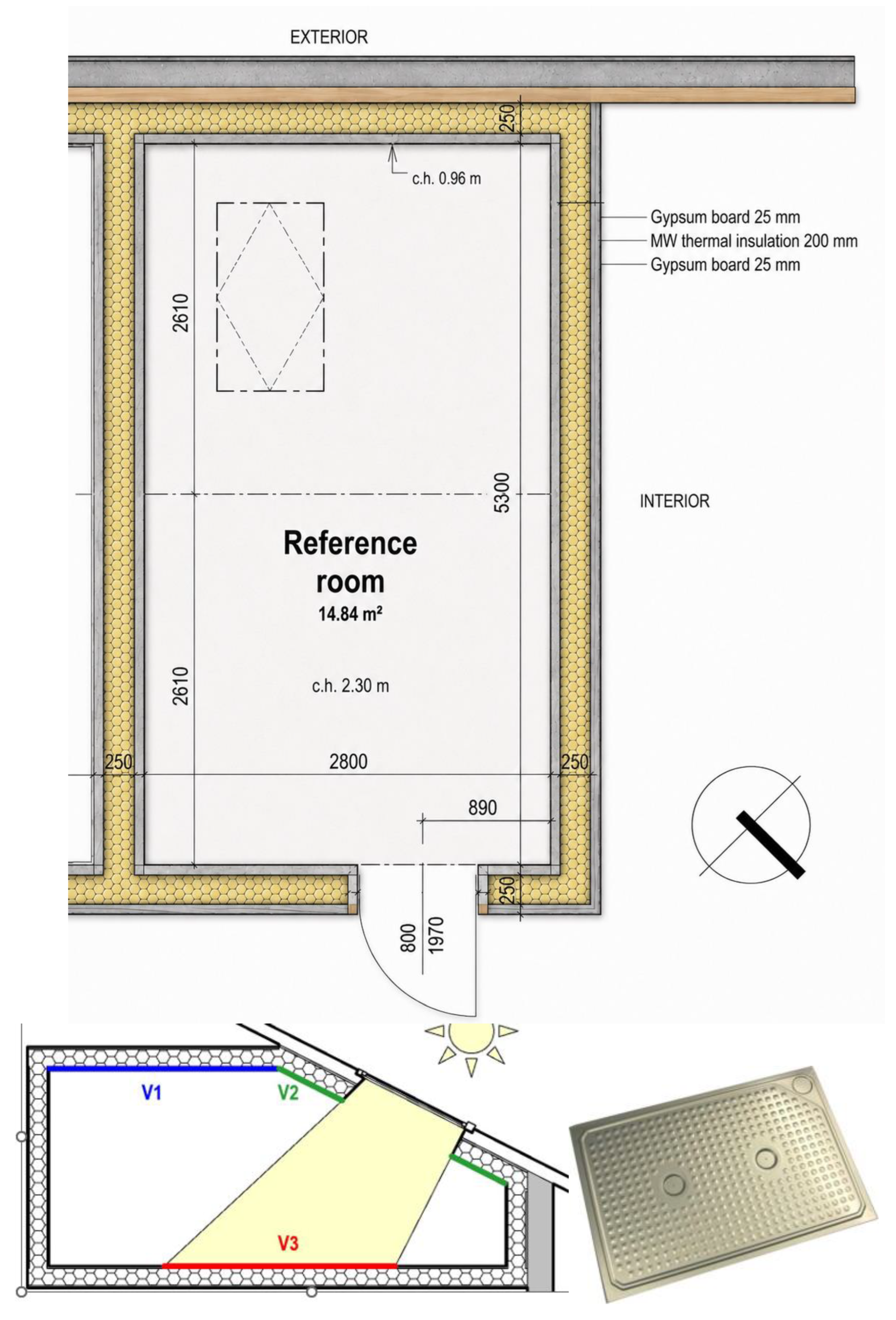
Figure 2.
Schematic layout of the proposed PCM composite integration variants (V1, V2, V3).
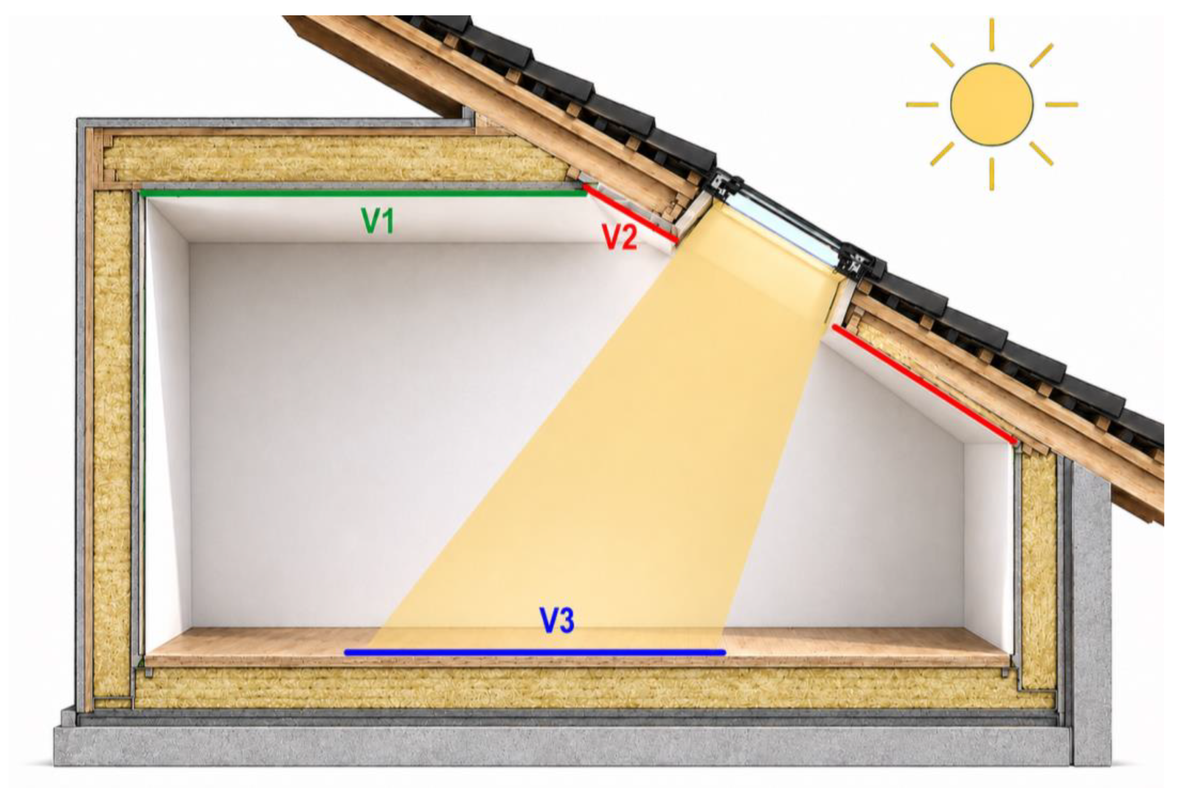
Figure 3.
Comparison of measured and simulated daily mean temperature of the reference room.
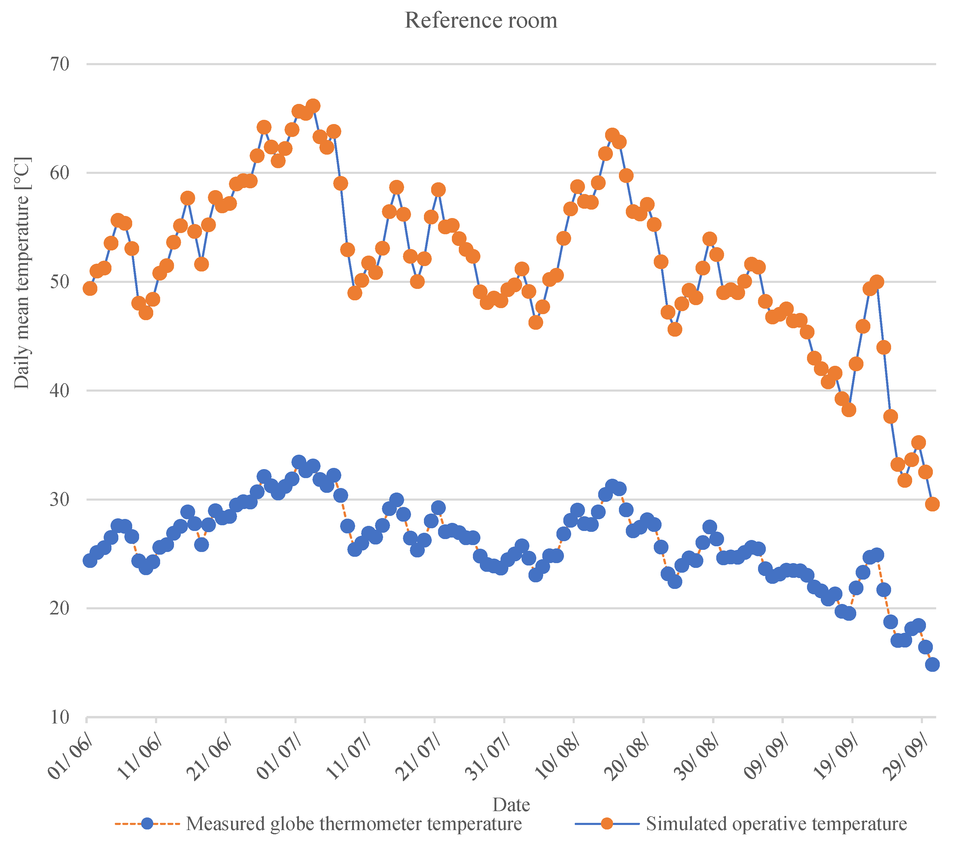
Figure 4.
Daily mean operative temperature over the entire monitoring period (20 mm).
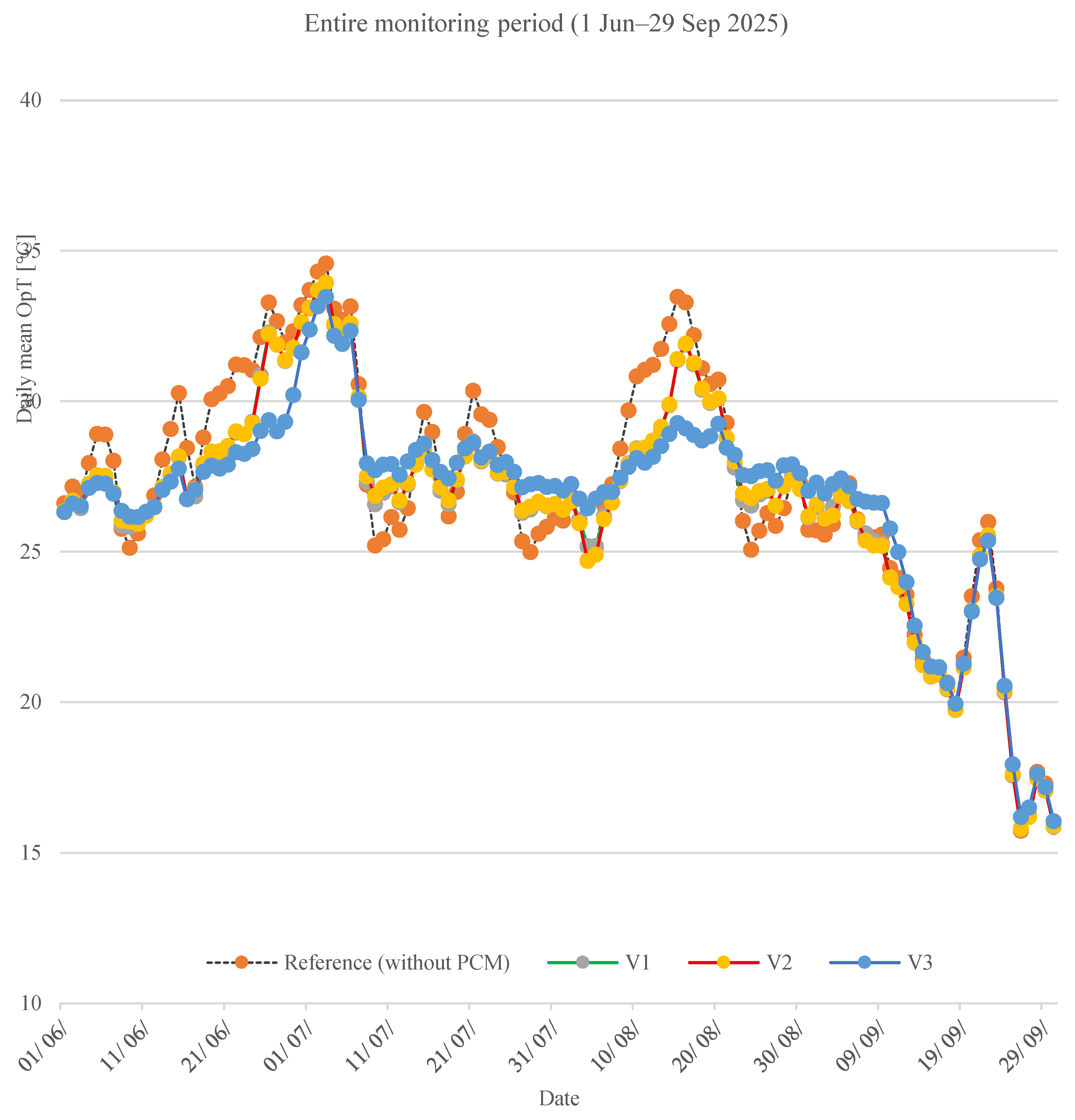
Figure 5.
Daily mean operative temperature during the hottest week (20 mm).
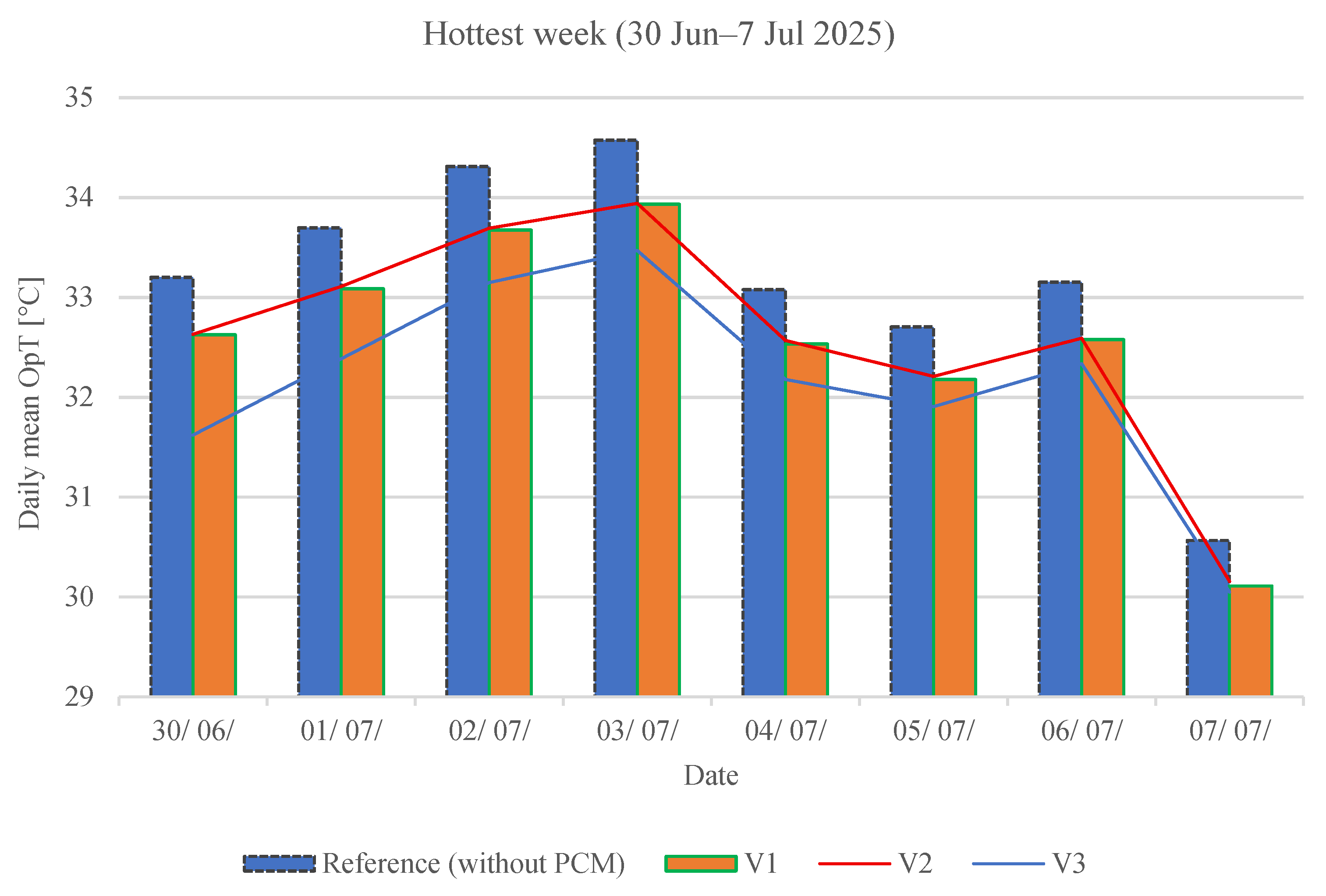
Figure 6.
Number of hours with operative temperature exceeding 26, 28, and 30 °C (20 mm).
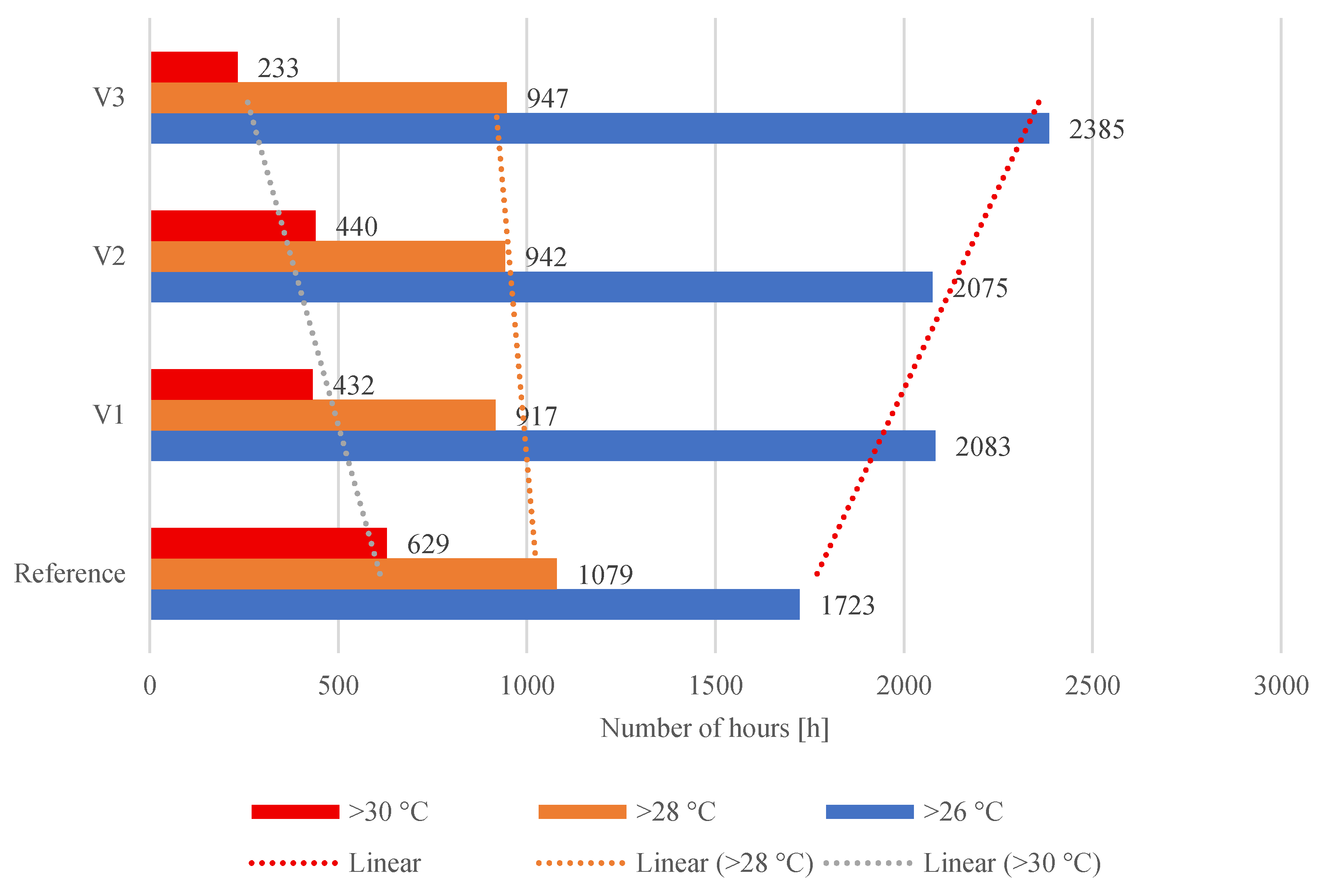
Figure 7.
Daily mean operative temperature during the hottest week (40 mm).
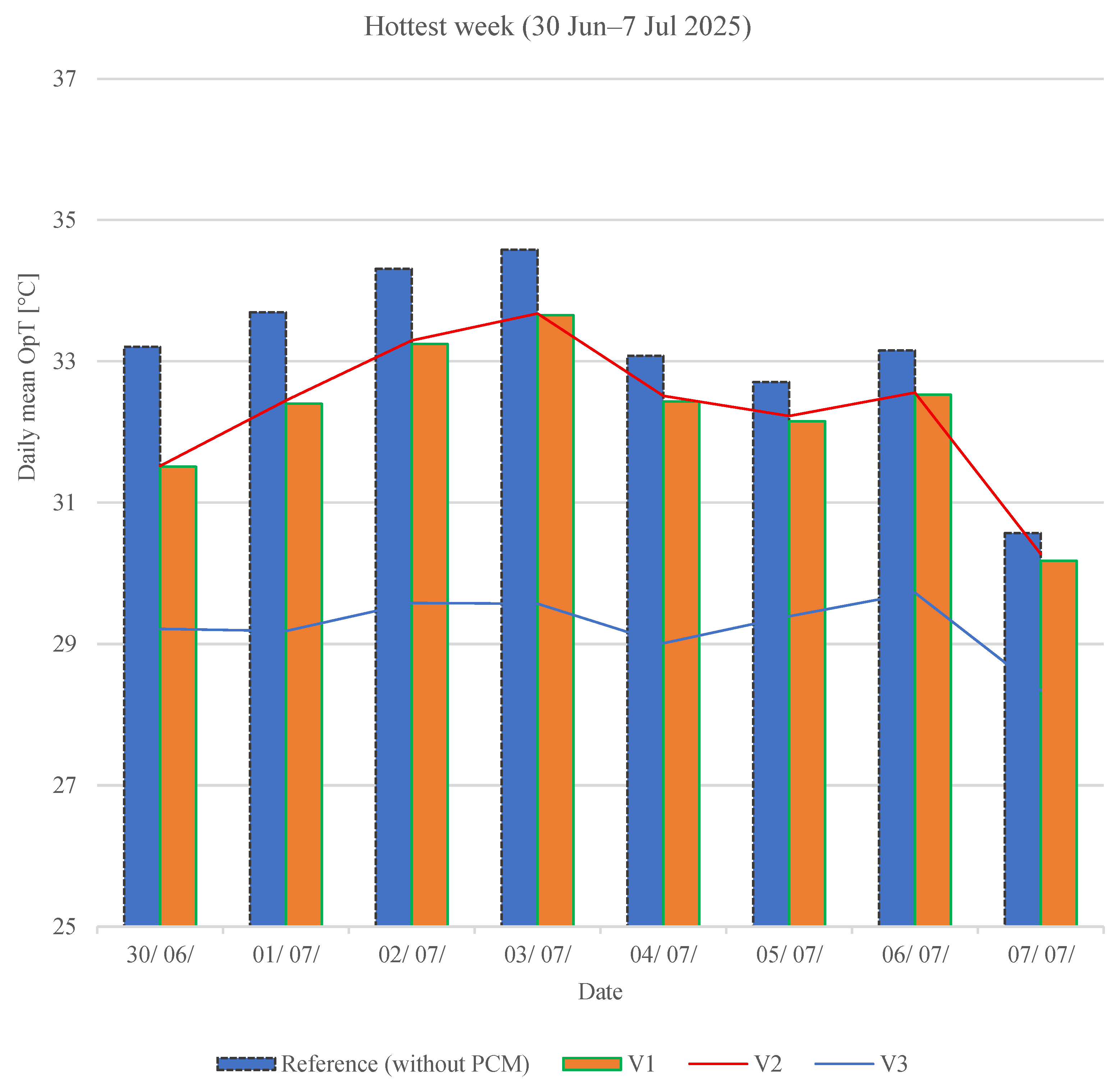
Figure 8.
Number of hours with operative temperature exceeding 26, 28, and 30 °C (40 mm).
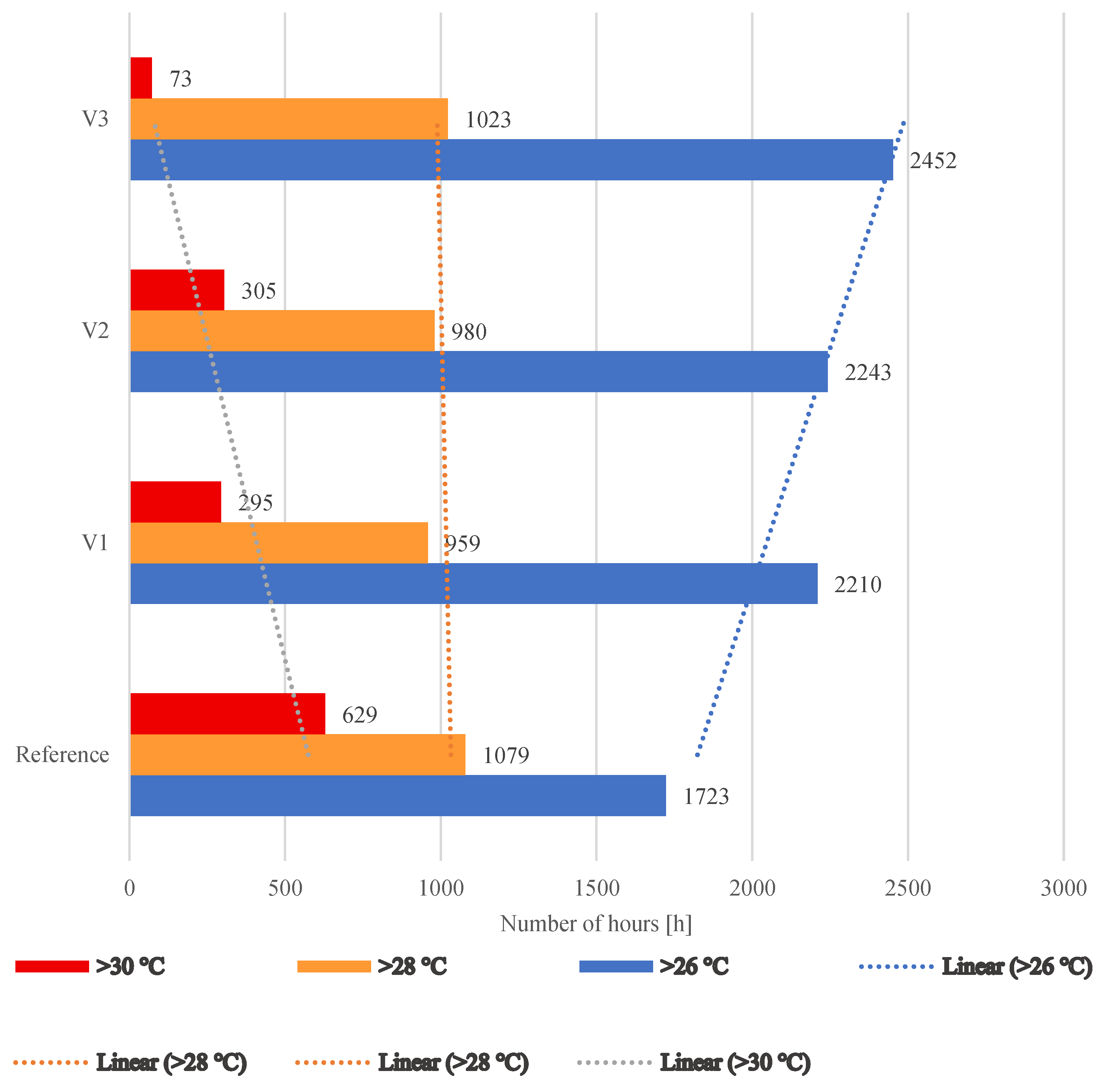

Table 1.
Input parameters of the reference room for the numerical model.
| Parameter | Value |
|---|---|
| Clear width × length (m) | 2.8 × 5.3 |
| Clear height (m) | 2.3 |
| Volume (m³) | 29.2 |
| Orientation | Southwest |
| Measurement period | 06–09/2025 |
| Wall composition (mm) | GB 25 + MW 200 + GB 25 |
Table 2.
Thermophysical properties of the PCM composite.
| Property | PCM (organic paraffin) | Aluminum |
|---|---|---|
| Density ρ [kg/m³] | 880 | 2700 |
| Thermal conductivity λ [W/(m·K)] | 0.2 | 237 |
| Specific heat capacity cp [kJ/(kg·K)] | 2.0 | 0.897 |
| Phase change onset temperature [°C] | 27 | - |
| Peak melting temperature [°C] | 29 | - |
| Phase change enthalpy [J/g] | 200 | - |
Table 3.
Proposed PCM composite integration variants.
| Variant | Location | Area [m2] | Description |
|---|---|---|---|
| V1 | Horizontal ceiling section | 7.48 | Coupled to indoor environment, secondary heat flux |
| V2 | Sloping roof section | 7.12 | Directly coupled to roof assembly, heat transfer through full envelope |
| V3 | Floor area below window | 7.40 | Direct solar radiation exposure, highest thermal load |
Table 4.
Summary meteorological indicators (1 June–30 September 2025).
| Month/Year | T_avg [°C] | T_max [°C] | T_min [°C] | R_max [W/m²] |
|---|---|---|---|---|
| 06/2025 | 20.5 | 35.2 | 8.3 | 948 |
| 07/2025 | 20.4 | 34.9 | 12.1 | 937 |
| 08/2025 | 20.4 | 35.1 | 6.4 | 925 |
| 09/2025 | 16.3 | 28.8 | 3.5 | 854 |
Table 5.
Statistical indicators of simulation model validation (122 days compared).
| Indicator | Reference room |
|---|---|
| MBE | -0.07 °C |
| MBE | -0.24 % |
| RMSE | 1.15 °C |
| CV(RMSE) | 4.34 % |
| MAE | 0.94 °C |
Table 6.
Comparison of maximum operative temperature for each variant at 20 mm thickness.
| Variant | OpT_max [°C] | ΔOpT_max [°C] |
|---|---|---|
| Reference (no PCM) | 34.58 | - |
| V1 (ceiling) | 33.93 | −0.65 |
| V2 (roof) | 33.94 | −0.64 |
| V3 (floor) | 33.47 | −1.11 |
Table 7.
Comparison of maximum operative temperature for each variant at 40 mm thickness.
| Variant | OpT_max [°C] | ΔOpT_max [°C] | |
|---|---|---|---|
| Reference (no PCM) | 34.58 | - | |
| V1 (ceiling) | 33.65 | −0.93 | |
| V2 (roof) | 33.68 | −0.90 | |
| V3 (floor) | 29.73 | −4.85 |
Disclaimer/Publisher’s Note: The statements, opinions and data contained in all publications are solely those of the individual author(s) and contributor(s) and not of MDPI and/or the editor(s). MDPI and/or the editor(s) disclaim responsibility for any injury to people or property resulting from any ideas, methods, instructions or products referred to in the content. |
© 2026 by the authors. Licensee MDPI, Basel, Switzerland. This article is an open access article distributed under the terms and conditions of the Creative Commons Attribution (CC BY) license (http://creativecommons.org/licenses/by/4.0/).
Copyright: This open access article is published under a Creative Commons CC BY 4.0 license, which permit the free download, distribution, and reuse, provided that the author and preprint are cited in any reuse.