Submitted:
29 May 2026
Posted:
03 June 2026
You are already at the latest version
Abstract
The development of steady-state advanced operation modes with high fusion gain (Q) is a primary objective of magnetic confinement fusion research. The advancement of high-temperature superconducting (HTS) magnet technology has introduced a new development path using devices like SPARC. This path contrasts with the conventional low-temperature superconducting (LTS) approach represented by devices such as BEST. This study utilizes the fast integrated modeling code METIS to compare the physical conditions required for an HTS-based (SPARC-like) and LTS-based (BEST-like) devices to achieve an energy gain of Q≈5. Furthermore, we simulated the achievable fusion power for both devices under an identical set of core physics parameters to isolate the effect of magnetic field strength. Simulation results show that at a similar Q≈5, the HTS device, leverages its high magnetic field to require significantly lower auxiliary heating power (approximately 50%-60% less). Additionally, it operates at a lower Greenwald density fraction (fGW≈0.37) than the LTS device (fGW≈0.87). This directly validates the strong dependence of the fusion triple product on magnetic field strength (∝B3). Under identical high-density ("BEST-like") parameters, the HTS device achieves much higher fusion power but faces a drastically increased L-H transition power threshold. This increase may force operation in L-mode. Crucially, even in L-mode, the high-field HTS device can still achieve Q>5 via high-density operation.
Keywords:
tokamak
; scenario design
; METIS
; fusion gain
; high-temperature superconductor
1. Introduction
Breakthroughs in rare-earth barium copper oxide (REBCO) high-temperature superconducting (HTS) tape technology have significantly advanced the development of compact, high-field tokamaks such as SPARC and ARC [1,2]. These devices offer a potentially faster and more economical path to fusion energy. A strong magnetic field () can significantly enhance plasma confinement and fusion reaction rates. Consequently, devices can achieve high fusion gain (Q) or even ignition with smaller size and lower auxiliary heating power [3,4].
However, high magnetic fields introduce new physics and engineering challenges. Higher fields typically lead to higher plasma density and pressure, which alters the physics of wave heating and current drive. For example, high fields affect the density cut-off for lower hybrid (LH) waves [5,6] and the absorption location of electron cyclotron (EC) waves [7,8,9]. Simultaneously, high-power-density operation places extreme demands on first-wall and divertor heat load management. Therefore, it is vital to systematically explore operational scenarios in high-field regimes using integrated modeling tools. Comparing these with conventional LTS device operation modes during the pre-design phase is of great importance.
Traditional high-fidelity 1.5D integrated codes (e.g., TRANSP, CRONOS) offer high accuracy but require long computation times, making extensive parameter scans difficult [10,11]. In contrast, the METIS code employs simplified physics models and empirical scaling laws. It achieves computation speeds far exceeding real-time while maintaining reasonable fidelity for key physical processes [12]. This makes METIS well-suited for rapid exploration of operational spaces and sensitivity analysis.
Based on this, this paper employs the METIS code to conduct a comparative study of advanced operation scenarios for an HTS-based device (using SPARC parameters as a reference) and an LTS-based device (using BEST parameters as a reference). We first validate the METIS configuration against published simulation data for SPARC. We then simulate the respective conditions required for each device to reach , comparing their demands on auxiliary heating power, density, and confinement level. Finally, we establish a common set of core physics parameters (aiming to control for the primary variable of magnetic field strength) to compare the ultimate fusion power and operational mode achievable by both devices. This study aims to reveal the impact of magnetic field strength on fusion device performance and provide reference for the physics design of subsequent high-field tokamak.
2. Materials and Methods
2.1. METIS Code Introduction
METIS (Minute Embedded Tokamak Integrated Simulator) is a fast integrated modeling code designed to simulate a full tokamak discharge lasting hundreds of seconds within minutes [12]. It adopts a hybrid 0D-1D approach: global 0D equations describe the evolution of integral quantities like plasma stored energy and current, while 1D diffusion equations calculate the transport of profile quantities such as temperature and current density.
Although METIS uses scaling laws to simplify physics models, its results remain reliable and consistent with 1.5D transport codes [12,13]. This is due to METIS’s 0D-1D approach to describing the transport of physical quantities, which are greatly influenced by turbulence and for which there are still large uncertainties in the simulation results of other first-principle based codes. The energy transport in METIS begins with a time-dependent 0D equation:
where is the plasma thermal energy content, is the energy confinement time, and is the total power loss through the plasma separatrix. Plasma confinement is modified by various processes, resulting in the total thermal energy expression:
where is a prescribed factor, is an internally computed confinement factor that takes into account the confinement degradation due to MHD phenomena (not considered in our simulations, i.e., ), is an internally computed confinement factor that takes into account the enhancement of the confinement due to the magnetic shear (considered in our simulations), allows to take into account the effect of internal inductance on energy confinement (not considered in our simulations i.e., ). is calculated using the ITER-98P(y,2) scaling law for the H-mode discharges. is defined as , where is the thermal energy in the pedestal region predicted by the scaling expression. The derivatives of electron and ion temperature with respect to the radial coordinate are then solved using diffusion transport equations, respectively. Although only the diffusion part is considered in the energy transport equation, the modified diffusion coefficients and , or alternatively conductivity coefficients , can be expressed by a prescribed analytical equation or theoretical model. In our simulations, the Current Diffusion Ballooning Mode (CDBM) [14] model is used to describe the shape of the transport coefficient. Thus, the temperature profiles are obtained by integrating the solved derivatives in the heat transport equations. The current diffusion component of METIS is completely implemented using the same method as the traditional 1.5D transport code, which evolves as a function of poloidal flux whose transport combines a 2D magnetic surface equilibrium with a 1D poloidal flux transport equation. The current diffusion equation includes several source terms that can be described by various physical models. The Sauter model [15] is used in this article to compute the bootstrap current. This model simplification is core to METIS’s computational speed. Although it sacrifices some first-principles detail, it has proven reliable for predicting overall performance trends [12,16].
2.2. Model Validation Based on SPARC Simulation Data
To ensure the reliability of the parameter settings and physics models used for the subsequent SPARC and BEST simulations, we first used METIS to reproduce a published full H-mode operational scenario for SPARC. The key parameters for this operating point are from published integrated modeling results [1,17], including: plasma current , toroidal field , major radius , minor radius , Greenwald density fraction , confinement factor , total heating power (of which, ).
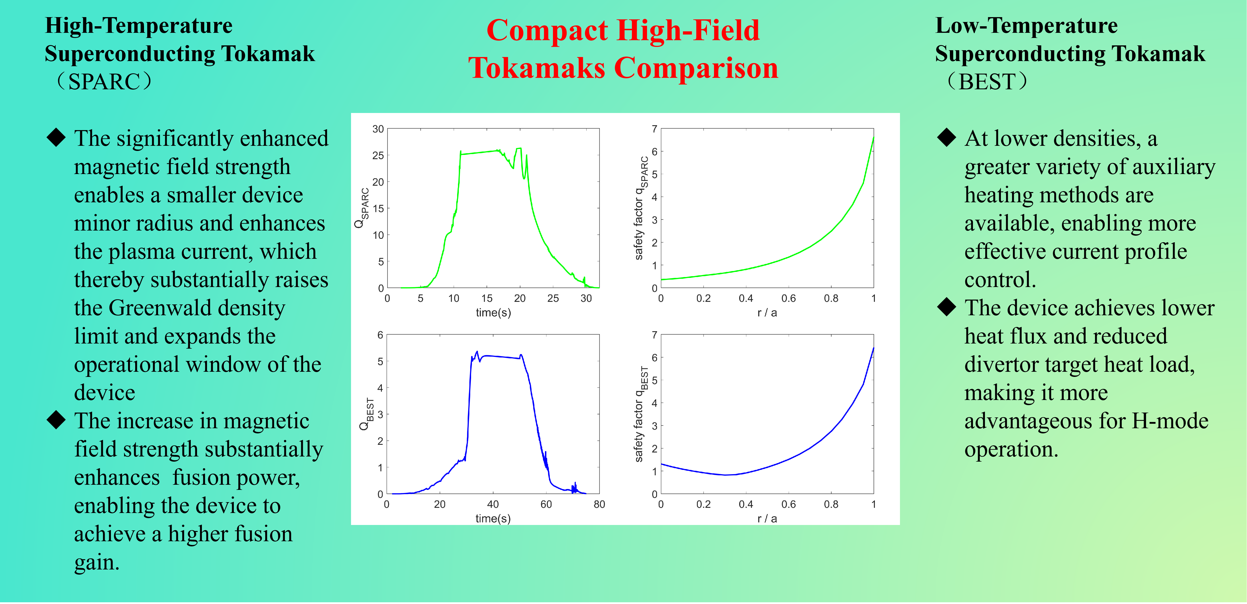
We configured METIS using the data from Table 1 and parameters from the references. The simulation was run for 35 seconds to reach a steady state. The outputs were compared with reference data for the same scenario, particularly the fusion power , fusion gain Q, and the current safety factor profile at the 95% flux surface. Figure 1 shows the fusion gain Q and the comparison between METIS simulation results and SPARC reference data for the evolution of safety factors and . It can be seen that the simulated and trends align well with the reference data, with minor numerical differences. In our simulation results, the central electron temperature is close to 25 keV, the central electron density is approximately , and the fusion gain . The differences from the reference data are within an acceptable margin of error(), thereby validating our METIS configuration.
2.3. Simulation Setup for BEST Scenarios
To explore the differences in parameters, performance, and operational scenarios between high-temperature superconducting (high-field) and low-temperature superconducting devices, we selected the SPARC (representing HTS high-field) and BEST (representing LTS) devices. Using METIS, we performed parameter scans to find operational scenarios achieving . During the scan, we first fixed some engineering and geometric parameters: BEST references published design parameters (m, m, , ) [18], and SPARC parameters are as previously described. Secondly, we selected the same energy scaling (ITER-98P(y,2) scaling law and ITER-89P(y,2) scaling law), density model (Angioni) [19,20], and transport model (CDBM). The core variables scanned were: line-averaged density (representing the Greenwald density fraction), impurity fraction, effective nuclear charge number , and heating power (including frequency, deposition location, width, etc.). Table 2 presents the key design parameters for operational scenarios., derived from literature references and parameter scan results. The parameter scan for BEST was conducted based on the operational scenario outlined in the BEST research plan. Figure 2 shows the METIS simulation results for the high fusion gain scenario in BEST. The results of the simulation profiles further reveal central electron temperatures of 26 keV and ion temperature of 33 keV at 45 s, accompanied by the formation of an internal transport barrier(ITB). A reversed-shear safety factor profile is also established with and . The parameter scan for SPARC was performed in accordance with the relevant SPARC literature, and the results are presented in Section 3.
3. Results and Discussion
3.1. Simulation Results for HTS Device (SPARC) at
Referring to SPARC design literature, auxiliary heating of SPARC employs only the ICRH minority ion heating scheme. Under its very high magnetic field (12.2 T) condition, it requires only a relatively low density to achieve a relatively high fusion power. Our scans indicate that SPARC, within the range of , , requires only about 15-20 MW of external heating power to achieve . Figure 3 illustrates some key parameters of a operating scenario ( ). The results of the simulation profiles further reveal central electron density of electron temperatures of 26 keV and ion temperature of 32 keV at 16 s. Compared with the SPARC reference data, this result shows an increased auxiliary heating power, a slightly reduced electron density, a significantly lower temperature, and consequently, a decreased fusion gain. The reductions in density and temperature diminish the fusion power, thereby lowering the fusion gain, while the increase in auxiliary heating power also contributes to a lower gain. The combined effect of these two factors results in a reduction of SPARC’s fusion gain from 11 to 5. This outcome is consistent with the underlying physics and represents a valid scientific result. It also can be seen that even with a confinement factor , which is lower than BEST (), SPARC can still achieve the same fusion gain target at a lower Greenwald density fraction. This is due to the high plasma pressure and fusion cross-section enabled by the high magnetic field. Unfortunately, a reversed-shear safety factor profile was not achieved in our simulations.
3.2. Comparison of Results for LTS(BEST) and HTS(SPARC) Devices
As shown in Figure 4, at the same fusion gain, the volume-averaged electron density of SPARC is higher than that of BEST, while its Greenwald density fraction is significantly lower. This is because the high magnetic field generated by SPARC’s high-temperature superconductors enables a more compact device with a smaller minor radius and a higher plasma current, meaning that SPARC’s Greenwald density limit is substantially higher than that of BEST. This implies that, compared to BEST, SPARC offers a wider operating parameter space—a key advantage of the high-temperature superconducting high-magnetic-field approach.
Overall, the comparison of simulation results clearly reveals the core advantages of the high-temperature superconducting high-field path:
- (1)
- Lower auxiliary heating power requirement: SPARC requires about 50%–60% less auxiliary heating power () than BEST (). This directly reduces the cost and complexity of external heating systems.
- (2)
- Lower operational density: SPARC can operate at , while BEST needs to operate near the Greenwald density limit (). Lower density operation favors wave heating (e.g., EC, LH) coupling and propagation, reduces plasma-wall interaction intensity, and may mitigate instabilities like edge-localized modes (ELM) [21].
- (3)
- More relaxed requirement on confinement factor: SPARC can achieve its target with , while BEST requires . This indicates that HTS high-field devices have higher “tolerance” for plasma confinement performance.
The physical root of these differences lies in the fusion triple product (for a fixed normalized beta ). To achieve a given fusion power (Q), a high magnetic field (B) can “compensate” for stringent requirements on density (n), temperature (T), or confinement time (, linearly related to ). Our simulation results quantitatively validate this fundamental relationship, proving that increasing the magnetic field strength is one of the most effective levers for enhancing fusion performance.
3.3. Comparison of Fusion Performance Under Identical Physics Parameters
To further isolate the effect of the magnetic field variable on enhancing fusion device performance, we designed a more “fair” comparison: applying an identical set of core physics parameters to both SPARC and BEST. These parameters include: volume-averaged heating power density (), confinement factor , Greenwald density fraction , and impurity content (). This means both devices operate in “similar” physical states but within different magnetic fields and sizes. We selected a typical high-density operating point from BEST as the parameter set: , ,
3.3.1. Fusion Power and Confinement
The simulation results (Figure 5) show that under the identical “BEST-like” physics parameters, SPARC, leveraging its 12.2 T field, achieved a very high fusion gain of () , whereas fusion gain of BEST was (). This visually demonstrates the enormous potential of a strong magnetic field for boosting fusion power.
However, high power density also brings challenges. The simulation shows that at such high density and pressure, the L-H transition power threshold for SPARC increases dramatically. The auxiliary heating power we initially set was insufficient to bring it into H-mode operation; that is, SPARC could only operate in L-mode under the initially set parameters. To better control the variables, we increased the auxiliary heating power of SPARC ( from 11.1 MW to 14.0 MW) to enable it to enter H-mode.
3.3.2. Discussion on the Feasibility of L-Mode Operation
Our simulations show that under high-field, high-density conditions, SPARC has a higher L-H transition threshold power. This makes entering H-mode more difficult. However, SPARC still achieves decent fusion gain in L-mode. Specifically, under conditions of high density (), and , the fusion gain reached approximately (Figure 6). This finding is significant: an operational strategy combining a strong magnetic field and high density can enable a device to achieve engineering-relevant fusion gain () without entering H-mode.
This has important implications for HTS device design. While H-mode offers better confinement, it often involves periodic edge-localized modes (ELM) [21]. ELM generate large thermal transients that can damage the first wall and divertor in compact devices like ARC or SPARC [1,22]. Therefore, proactively choosing to operate in an ELM-free L-mode may be a more robust and viable scheme [22]. By appropriately increasing the operational density (), the fusion power loss from poorer L-mode confinement can be compensated for.
3.4. Challenge of Current Drive and Profile Control
Another prominent issue in our simulation process is current profile control. Under high-density () conditions, EC and LH waves face limitations due to density cut-offs and wave accessibility issues, making it difficult to effectively heat and drive core plasma current [23]. NBI (neutral beam injection) heating also struggles to heat the core plasma [24]. Therefore, the primary method for auxiliary heating of SPARC is ICRH. The ICRH minority ion heating scheme can efficiently heat ions, but its contribution to current drive is limited, and its driven current profile is broad and difficult to tailor flexibly. This makes it difficult for the final current distribution to exhibit an inverse shear configuration, and also hinders the formation of the internal transport barrier (ITB)—resulting in the inability to achieve advanced operating modes.
Because BEST employs four auxiliary heating methods (ECRH, LH, NBI, and ICRH) and has higher total auxiliary heating power, it can drive more current and provide more flexible current profile control. This makes it easier for the final current profile to exhibit a reverse magnetic shear shape.
This highlights a key dilemma: The high-density operational mode pursued by HTS devices for high power density inherently restricts the use of tools most commonly used for fine control of the current profile (e.g., off-axis ECCD, LHCD). In the SPARC simulation, the total current profile is dominated by ohmic and bootstrap currents, with a low fraction of auxiliary driven current that is difficult to adjust flexibly. This makes it very challenging to actively control the current profile to form and sustain advanced operational modes with reverse magnetic shear [25] or internal transport barriers (ITB) [26]. Developing effective methods for current profile control under high-density, high-field conditions is a major challenge that must be addressed in the future physics design of HTS devices.
3.5. Overview and Discussion
The study quantitatively demonstrates the performance leverage provided by high magnetic fields in tokamak. The HTS path (exemplified by SPARC) significantly lowers the entry barriers to high fusion gain by reducing demands on auxiliary heating power, plasma density, and confinement quality compared to the conventional LTS path (exemplified by BEST). This advantage stems directly from the scaling of the fusion triple product, which our simulations have validated.
However, the pursuit of high-power density through high fields and high densities introduces significant trade-offs. The most critical is the challenge to active current profile control. High densities render common tools like EC and LH waves ineffective, forcing reliance on ICRH, which is a poor current driver. This limits the ability to establish and sustain advanced, high-performance scenarios like those with reverse magnetic shear or internal transport barriers, which are often desired for steady-state operation.
Furthermore, the increased L-H transition power threshold at high field and density may preclude H-mode operation, forcing the device into L-mode. While our simulations show that is still achievable in L-mode for HTS devices, this operational regime typically has poorer energy confinement. This necessitates even higher density to compensate, which in turn exacerbates the current drive challenges. Therefore, the operational space for compact high-field devices like SPARC or ARC may involve a complex optimization between confinement mode, density, and current drive capability. The potential benefit of avoiding ELM-induced heat loads by operating in L-mode [22] must be carefully weighed against the confinement penalty and the increased difficulty in controlling the current profile.
4. Conclusions
This study employed the fast integrated modeling code METIS to systematically compare the physical characteristics and requirements for achieving high fusion gain operation in high-temperature superconducting (SPARC) and low-temperature superconducting (BEST) tokamak, representing different technological paths. The main conclusions are as follows:
The high-field HTS device (SPARC) demonstrates significant advantages in achieving the same fusion gain (): it requires 50-60% less auxiliary heating power, operates at a lower Greenwald density fraction requirement (), and has a more relaxed requirement for the energy confinement factor (). This quantitatively validates the strong dependence of fusion performance on magnetic field strength.
Under an identical set of high-density physics parameters, fusion power potential of SPARC far exceeds that of BEST, but H-mode transition power threshold of SPARC is also significantly increased, likely forcing operation in L-mode. However, simulations indicate that even in L-mode, SPARC can still achieve through high-density operation. This suggests a potential fallback operational strategy for compact HTS devices facing severe first-wall heat load challenges: proactively choosing to operate in an L-mode without large ELM.
However, high-density operation severely limits the application of heating methods such as ECRH and LH, making HTS devices heavily reliant on ICRH. This single auxiliary heating scheme cannot drive sufficient current to adjust the current profile, making it difficult to establish and maintain advanced operating modes such as reverse shearing [25] or ITB (internal transport barriers) [26]. This poses new challenges for current profile control. Developing efficient, controllable non-inductive current drive methods suitable for high-density, high-field plasmas may be a key point for future research.
Looking ahead, HTS magnet technology opens a new development path for fusion energy characterized by high magnetic fields and compactness. This study reveals the great potential of this new path compared to the previous LTS path in lowering the barriers to fusion (auxiliary heating power, confinement requirements), and also identifies its core physics challenges (current drive and profile control at high density, higher L-H transition threshold power). Follow-up work needs to incorporate more precise wave physics and current drive calculations to explore possible current profile control schemes at high density. Simultaneously, for future higher-parameter steady-state operation devices like ARC and CFEDR, it is necessary to further explore the operational characteristics and scenarios of HTS and LTS devices to provide guidance for the design of commercial fusion reactor.
Author Contributions
Conceptualization, F.J. Wang and G.S. Xu; methodology, F.J. Wang and G.S. Xu; validation, F.J. Wang; formal analysis, F.J. Wang and J.R. Wu; investigation, F.J. Wang, J.R. Wu, G.S. Xu and M.H. Li; resources, M.H. Li and Y. Tao; writing—original draft preparation, F.J. Wang; writing—review and editing, F.J. Wang and G.S. Xu; visualization, F.J. Wang and J.R. Wu. All authors have read and agreed to the published version of the manuscript.
Funding
This research received no external funding.
Institutional Review Board Statement
Not applicable.
Informed Consent Statement
Not applicable.
Data Availability Statement
The data presented in this study are available in this article.
Conflicts of Interest
The authors declare no conflicts of interest.
References
- Creely, A.J.; Greenwald, M.J.; Ballinger, S.B.; Brunner, D.; Canik, J.; Doody, J.; Fülöp, T.; Garnier, D.T.; Granetz, R.; Gray, T.K.; et al. Overview of the SPARC Tokamak. J. Plasma Phys. 2020, 86, 865860502. [Google Scholar] [CrossRef]
- Olynyk, G.M.; Hartwig, Z.S.; Whyte, D.G.; Barnard, H.S.; Bonoli, P.T.; Bromberg, L.; Garrett, M.L.; Haakonsen, C.B.; Mumgaard, R.T.; Podpaly, Y.A. Vulcan: A Steady-State Tokamak for Reactor-Relevant Plasma–Material Interaction Science. Fusion Eng. Des. 2012, 87, 224–233. [Google Scholar] [CrossRef]
- Sorbom, B.N.; Ball, J.; Palmer, T.R.; Mangiarotti, F.J.; Sierchio, J.M.; Bonoli, P.; Kasten, C.; Sutherland, D.A.; Barnard, H.S.; Haakonsen, C.B.; et al. ARC: A Compact, High-Field, Fusion Nuclear Science Facility and Demonstration Power Plant with Demountable Magnets. Fusion Eng. Des. 2015, 100, 378–405. [Google Scholar] [CrossRef]
- Costley, A.E. On the Fusion Triple Product and Fusion Power Gain of Tokamak Pilot Plants and Reactors. Nucl. Fusion 2016, 56, 066003. [Google Scholar] [CrossRef]
- Li, M.H.; Xu, H.D.; Wang, X.J.; Wang, M.; Ding, B.J.; Wu, C.B.; Yan, G.H.; Liu, L.; Zhao, L.M.; Wu, Z.G.; et al. Plasma Heating by Electron Cyclotron Wave and the Temperature Effects on Lower Hybrid Current Drive on EAST. Nucl. Fusion 2023, 63, 046019. [Google Scholar] [CrossRef]
- Ding, B.J.; Li, M.H.; Li, Y.C.; Cesario, R.; Tuccillo, A.A.; Parker, R.; Baek, S.G.; Wang, Y.F.; Liu, H.Q.; Xu, J.C.; et al. Correlation between the Onset of Parametric Instability of Lower Hybrid Waves and Modification in Edge Plasma Current Profile on EAST. Nucl. Fusion 2018, 58, 126015. [Google Scholar] [CrossRef]
- Giruzzi, G.; Artaud, J.F.; Dumont, R.J.; Imbeaux, F.; Bibet, P.; Berger-By, G.; Bouquey, F.; Clary, J.; Darbos, C.; Ekedahl, A.; et al. Synergy of Electron-Cyclotron and Lower-Hybrid Current Drive in Steady-State Plasmas. Phys. Rev. Lett. 2004, 93, 255002. [Google Scholar] [CrossRef]
- Du, H.; Ding, S.; Chen, J.; Wang, Y.; Lian, H.; Xu, G.; Zhai, X.; Liu, H.; Zang, Q.; Lyu, B.; et al. Analysis of Performance Degradation in an Electron Heating Dominant H-Mode Plasma after ECRH Termination in EAST. Nucl. Fusion 2018, 58, 066011. [Google Scholar] [CrossRef]
- Cirant, S.; Airoldi, A.; Bertalot, L.; Bruschi, A.; Bracco, G.; Buratti, P.; Cenacchi, G.; Esposito, B.; Granucci, G.; Kroegler, H.; et al. ECRH at High Heating Power Density in FTU Tokamak. Fusion Eng. Des. 2001, 53, 301–308. [Google Scholar] [CrossRef]
- Hawryluk, R.J. AN EMPIRICAL APPROACH TO TOKAMAK TRANSPORT. In Physics of Plasmas Close to Thermonuclear Conditions; Elsevier, 1981; pp. 19–46. ISBN 978-1-4832-8385-2. [Google Scholar]
- Artaud, J.F.; Basiuk, V.; Imbeaux, F.; Schneider, M.; Garcia, J.; Giruzzi, G.; Huynh, P.; Aniel, T.; Albajar, F.; Ané, J.M.; et al. The CRONOS Suite of Codes for Integrated Tokamak Modelling. Nucl. Fusion 2010, 50, 043001. [Google Scholar] [CrossRef]
- Artaud, J.F.; Imbeaux, F.; Garcia, J.; Giruzzi, G.; Aniel, T.; Basiuk, V.; Bécoulet, A.; Bourdelle, C.; Buravand, Y.; Decker, J.; et al. Metis: A Fast Integrated Tokamak Modelling Tool for Scenario Design. Nucl. Fusion 2018, 58, 105001. [Google Scholar] [CrossRef]
- Li, Y.C.; Li, M.H.; Ding, B.J.; Artaud, J.F.; Peysson, Y.; Ekedahl, A.; Wang, M.; Wang, X.J.; Xu, H.D.; Shan, J.F.; et al. Predictive Simulations of Operation Scenarios for EAST with METIS Code. J. Plasma Phys. 2017, 83, 905830404. [Google Scholar] [CrossRef]
- Itoh, S.-I.; Itoh, K.; Fukuyama, A. Model of a Giant ELM. Plasma Phys. Control. Fusion 1996, 38, 1367. [Google Scholar] [CrossRef]
- Sauter, O.; Angioni, C.; Lin-Liu, Y.R. Neoclassical Conductivity and Bootstrap Current Formulas for General Axisymmetric Equilibria and Arbitrary Collisionality Regime. Phys. Plasmas 1999, 6, 2834–2839. [Google Scholar] [CrossRef]
- Tao, Y.; Li, M.H.; Qian, J.P.; Moreau, D.; Zhang, B.; Xu, H.D.; Xu, W.Y.; Li, P.; Yang, X.D.; Liu, W.B.; et al. Simulation of Current Density Profile for EAST Advanced Scenario with METIS Code. Fusion Eng. Des. 2024, 200, 114177. [Google Scholar] [CrossRef]
- Rodriguez-Fernandez, P.; Howard, N.T.; Greenwald, M.J.; Creely, A.J.; Hughes, J.W.; Wright, J.C.; Holland, C.; Lin, Y.; Sciortino, F.; the SPARC team. Predictions of Core Plasma Performance for the SPARC Tokamak. J. Plasma Phys. 2020, 86, 865860503. [Google Scholar] [CrossRef]
- Version 1 - ipp.cas.cn. Available online: https://www.ipp.cas.cn/zhuanti/xzzq/202511/P020251202378339008205.pdf.
- Angioni, C.; Weisen, H.; Kardaun, O.J.W.F.; Maslov, M.; Zabolotsky, A.; Fuchs, C.; Garzotti, L.; Giroud, C.; Kurzan, B.; Mantica, P.; et al. Scaling of Density Peaking in H-Mode Plasmas Based on a Combined Database of AUG and JET Observations. Nucl. Fusion 2007, 47, 1326. [Google Scholar] [CrossRef]
- Angioni, C.; Mantica, P.; Pütterich, T.; Valisa, M.; Baruzzo, M.; Belli, E.A.; Belo, P.; Casson, F.J.; Challis, C.; Drewelow, P.; et al. Tungsten Transport in JET H-Mode Plasmas in Hybrid Scenario, Experimental Observations and Modelling. Nucl. Fusion 2014, 54, 083028. [Google Scholar] [CrossRef]
- Bécoulet, M.; Huysmans, G.; Thomas, P.; Ghendrih, P.; Nardon, E.; Grosman, A.; Garbet, X.; Zwingman, W.; Moyer, R.; Evans, T.; et al. Edge Localized Modes Control by Stochastic Magnetic Fields. Nucl. Fusion 2005, 45, 1284. [Google Scholar] [CrossRef]
- Frank, S.J.; Perks, C.J.; Nelson, A.O.; Qian, T.; Jin, S.; Cavallaro, A.; Rutkowski, A.; Reiman, A.; Freidberg, J.P.; Rodriguez-Fernandez, P.; et al. Radiative Pulsed L-Mode Operation in ARC-Class Reactors. Nucl. Fusion 2022, 62, 126036. [Google Scholar] [CrossRef]
- Giruzzi, G. Impact of Electron Trapping on RF Current Drive in Tokamaks. Nucl. Fusion 1987, 27, 1934. [Google Scholar] [CrossRef]
- Liang, Z.; Liu, H.; Du, H.F.; Chen, B.; Yang, Y.M.; Xie, H.S.; Dai, S.Y.; Wang, D.Z. Assessments of the Performance of Neutral Beam Injection on the Spherical Tokamak EXL-50. Fusion Eng. Des. 2022, 180, 113189. [Google Scholar] [CrossRef]
- Strait, E.J. Enhanced Confinement and Stability in DIII-D Discharges with Reversed Magnetic Shear. Phys. Rev. Lett. 1995, 75, 4421–4424. [Google Scholar] [CrossRef]
- Chu, Y.Q.; Liu, H.Q.; Zhang, S.B.; Xu, L.Q.; Li, E.Z.H.; Jie, Y.X.; Lian, H.; Zhou, T.F.; Feng, X.; Zhang, X.X. Magnetohydrodynamic Effect of Internal Transport Barrier on EAST Tokamak. Plasma Sci. Technol. 2022, 24, 035102. [Google Scholar] [CrossRef]
Figure 1.
(a) The comparison between our simulation results and SPARC reference data for the evolution of safety factors and . (b) SPARC fusion gain (Q) in our simulation results.
Figure 1.
(a) The comparison between our simulation results and SPARC reference data for the evolution of safety factors and . (b) SPARC fusion gain (Q) in our simulation results.

Figure 2.
METIS simulation results for the high fusion gain scenario in BEST. (a) electron density and ion density profile; (b) electron temperature and ion temperature profile; (c) safety factor profile; (d) fusion gain. All profile data were acquired during the current flat-top phase.
Figure 2.
METIS simulation results for the high fusion gain scenario in BEST. (a) electron density and ion density profile; (b) electron temperature and ion temperature profile; (c) safety factor profile; (d) fusion gain. All profile data were acquired during the current flat-top phase.

Figure 3.
METIS simulation results for the fusion gain scenario in SPARC. (a) electron density and ion density profile; (b) electron temperature and ion temperature profile; (c) safety factor profile; (d) fusion gain. All profile data were acquired during the current flat-top phase.
Figure 3.
METIS simulation results for the fusion gain scenario in SPARC. (a) electron density and ion density profile; (b) electron temperature and ion temperature profile; (c) safety factor profile; (d) fusion gain. All profile data were acquired during the current flat-top phase.

Figure 4.
Comparison of results for LTS(BEST) and HTS(SPARC) devices. (a) SPARC volume-averaged electron density; (b) SPARC total plasma pressure; (c) BEST volume-averaged electron density; (d) BEST total plasma pressure.
Figure 4.
Comparison of results for LTS(BEST) and HTS(SPARC) devices. (a) SPARC volume-averaged electron density; (b) SPARC total plasma pressure; (c) BEST volume-averaged electron density; (d) BEST total plasma pressure.

Figure 5.
The comparations for fusion performance of BEST and SPARC under identical physical parameters. (a) electron temperature profile; (b) SPARC fusion gain; (c) safety factor profile; (d) BEST fusion gain. All profile data were acquired during the current flat-top phase.
Figure 5.
The comparations for fusion performance of BEST and SPARC under identical physical parameters. (a) electron temperature profile; (b) SPARC fusion gain; (c) safety factor profile; (d) BEST fusion gain. All profile data were acquired during the current flat-top phase.

Figure 6.
METIS simulation results for L-mode scenario in SPARC. (a) electron density and ion density profile; (b) electron temperature and ion temperature profile; (c) safety factor profile; (d) fusion gain. All profile data were acquired during the current flat-top phase.
Figure 6.
METIS simulation results for L-mode scenario in SPARC. (a) electron density and ion density profile; (b) electron temperature and ion temperature profile; (c) safety factor profile; (d) fusion gain. All profile data were acquired during the current flat-top phase.


Table 1.
Design parameters for various operating scenarios in SPARC references.
| Parameter | Full-field H-mode | Full-field L-mode |
|---|---|---|
| Toroidal Field (T) | 12.2 | 12.2 |
| Plasma Current (MA) | 8.7 | 8.7 |
| Safety Factor | 3.05 | 3.05 |
| Normalized Beta | 0.029 | 0.0073 |
| Confinement Factor | 1.0 | 1.0 |
| Energy Confinement Time (s) | 0.77 | 0.44 |
| Total Aux. Power (MW) | 11.1 | 24.1 |
| Ohmic Heating Power (MW) | 1.7 | 1.1 |
| Effective Charge | 1.5 | 1.5 |
| Main ion dilution | 0.85 | 0.85 |
| Volume Avg. (keV) | 7.3 | 9.7 |
| Volume Avg. (keV) | 7.3 | 9.7 |
| Volume Avg. () | 3.1 | 1.4 |
| Volume Avg. () | 2.7 | 1.2 |
| Peak Factor | 2.5 | 2.5 |
| Peak Factor | 1.33 | 1.51 |
| Greenwald Fraction | 0.37 | 0.16 |
| Toroidal Beta | 0.012 | 0.007 |
| Normalized Beta | 1.0 | 0.6 |
| Fusion Power (MW) | 140 | 55 |
Table 2.
Operational scenario design parameters for SPARC and BEST.
| Parameter | SPARC | BEST | SPARC |
|---|---|---|---|
| Major Radius R (m) | 1.85 | 3.6 | 1.85 |
| Minor Radius a (m) | 0.57 | 1.1 | 0.57 |
| Toroidal Field (T) | 12.2 | 6.15 | 12.2 |
| Triangularity | 0.43 | 0.51 | 0.43 |
| Elongation | 1.72 | 1.87 | 1.72 |
| Confinement Factor | 1 | 1.2 | 1.2 |
| Fusion Power (MW) | 92 | 200 | 420 |
| Fusion Gain Q | 5.5 | 5 | 27 |
| Plasma Current (MA) | 7.5 | 7 | 7 |
| Safety Factor | 4.05 | 4.7 | 4.6 |
| Normalized Beta | 1.00 | 2.7 | 2.5 |
| Poloidal Beta | 0.46 | 1.3 | 1.4 |
| Volume Avg. / Peak (keV) | 6.6 / 16.6 | 7.3 / 26 | 5.8 / 24 |
| Volume Avg. / Peak () | 2.6 / 3.1 | 1.3 / 1.8 | 7.1 / 7.4 |
| Greenwald Fraction | 0.37 | 0.87 | 0.85 |
| Effective Charge | 1.38 | 1.53 | 1.72 |
| Total Aux. Power (MW) | 16.63 | 40 | 14 |
| LHCD Power (MW) | 0 | 10 | 0 |
| ECCD Power (MW) | 0 | 10 | 0 |
| ICRF Power (MW) | 16.63 | 10 | 14 |
| NBI Power (MW) | 0 | 10 | 0 |
Note: The data in the table are derived from METIS simulation results, references on relevant devices, and the input parameters we set for comparison.
Disclaimer/Publisher’s Note: The statements, opinions and data contained in all publications are solely those of the individual author(s) and contributor(s) and not of MDPI and/or the editor(s). MDPI and/or the editor(s) disclaim responsibility for any injury to people or property resulting from any ideas, methods, instructions or products referred to in the content. |
© 2026 by the authors. Licensee MDPI, Basel, Switzerland. This article is an open access article distributed under the terms and conditions of the Creative Commons Attribution (CC BY) license (http://creativecommons.org/licenses/by/4.0/).
Copyright: This open access article is published under a Creative Commons CC BY 4.0 license, which permit the free download, distribution, and reuse, provided that the author and preprint are cited in any reuse.


