

Submitted:
23 May 2026
Posted:
25 May 2026
You are already at the latest version
Abstract
Wavy microchannels have been shown to enhance the heat transfer performance of microchannel heat sinks compared to straight microchannels. The present study introduces a bidirectional curved wavy microchannel design aimed at enhancing performance. Numerical simulations are conducted to investigate the thermo-hydraulic behavior of bidirectional curved and ordinary wavy microchannel under constant heat flux conditions, with Reynolds numbers ranging from 300 to 800. The results indicate that the bidirectional curved microchannel achieves optimal performance at an inlet velocity of 0.6 m/s. Compared with the ordinary wavy microchannel, the Nusselt number of the bidirectional curved wavy microchannel increases by 95.3%. The average secondary flow intensity in bidirectional curved wavy microchannels with A2 = 2 mm and λ2 = 12 mm is enhanced by 153%. The enhanced heat transfer is attributed to the increased main flow velocity and the secondary flow intensity due to the bidirectional curved, which promote coolant mixing.
Keywords:
bidirectional curved wavy microchannel
; thermo-hydraulic performance
; secondary flow
1. Introduction
In recent years, advancements in technology and increasing demand have placed greater emphasis on high-performance and safe thermal solutions. This demand is particularly prominent in the fields of electronic equipment cooling [1] and power battery thermal management [2]. The concept of microchannels was first proposed by Tuckerman and Pease [3]. Microchannel heat sinks are valued for their superior heat dissipation capabilities, withstanding heat fluxes of up to approximately 100 W/cm2, and offering advantages such as small size, light weight, compactness, and low coolant requirements [4]. In traditional straight microchannels, heat transfer performance diminishes over time due to the thickening of the flow boundary layer, leading to a larger temperature gradient across the channels, especially under high heat fluxes. When fluid flows through a curved pipe at sufficient velocity, centrifugal force generates secondary vortices in the transverse plane. These vortices enhance fluid mixing and heat transfer. Inspired by these vortices, researchers have explored various types of curved microchannels.
Sui et al. [5] proposed a sinusoidal wavy microchannel and compared it with the conjugate heat transfer simulation of ordinary straight microchannel under constant heat flux and constant wall temperature conditions. Later, Sui et al. [6] experimentally investigated the flow friction and heat transfer in rectangular sinusoidal microchannels, and verified the comprehensive enhancement effect of sinusoidal microchannels. Moreover, the results also indicated that the quantity and the location of the vortices may change along the flow direction, leading to chaotic advection, which significantly enhances the convective fluid mixing. It was also suggested that the relative wave amplitude of the microchannel along the flow direction could be adjusted based on actual heat dissipation needs, effectively addressing local overheating issues. Similarly, M. Khoshvaght-Aliabadi et al. [7] experimentally evaluated the performance of wavy microchannel heat sinks. Their results showed that the heat dissipation capability of wavy microchannel heat sinks is superior to that of straight microchannel heat sinks. M. Khoshvaght-Aliabadi et al. [8] and Lin et al. [9] further proposed a wavy channel design in which the wavelength decreases or amplitude increases along the flow direction. This design exhibited lower thermal resistance and more uniform bottom wall temperature distribution. Some studies have also proved the influence of wavelength and amplitude on the wave shape performance [10,11,12,13]. Various channel shapes, including zigzag, curvy, and step, have been investigated to identify the optimal heat sink design [14,15]. Among these, zigzag channels consistently demonstrate superior heat transfer performance compared to other tortuous shapes. Sharma and Khan [16] compared the thermo-hydraulic performance of elliptical-wavy and sinusoidal-wavy microchannels and found that elliptical-wavy microchannels generally exhibit better thermo-hydraulic performance than sinusoidal-wavy microchannels across most models. In addition to parallel wavy walls, microchannels can also be designed with converging–diverging symmetric wavy walls [17,18,19]. However, symmetric wavy ones appear to have worse thermal performance than parallel wavy ones. Then, Zhu et al. [20] integrated symmetrical sinusoidal sidewalls and rectangular rib prisms in microchannels. Hasis et al. [13] proposed a twisted sinusoidal wavy microchannel. To address the limitations of wavy microchannels in compact structures, Zhang et al. [21] proposed a curved-wavy channel.
In addition to studies focusing on the structural characteristics of wavy microchannels themselves, there has also been extensive research on wavy microchannel heat sinks. Numerical studies conducted by Hung et al. [22] demonstrated that the thermal performance of the double-layered microchannel heat sink is better than that of the single-layered one, by an average of 6.3%. Xie et al. [23] pointed out that the double-layer wavy microchannel heat sink not only improves the heat transfer, but also reduces the pressure drop loss compared with the single-layer wavy microchannel heat sink. Moreover, double-layered microchannel heat sinks with a counter-flow configuration show a better cooling uniformity than those with a parallel-flow configuration [24]. Additionally, to address the design challenges of using either the upper-lower or left-right wave shapes in microchannel heat sinks, Zhu et al. [25] investigated the overall thermal resistance and maximum bottom wall temperature variations of these two wavy microchannel designs under the constant pumping power. The differences in heat transfer performance between the two designs at small wavelengths are attributed to the distinct positions of the generated Dean vortices.
In the field of thermal management for cylindrical lithium-ion batteries, wavy microchannels have attracted considerable attention due to their ability to conform to battery curvature, increase contact area, and enhance heat transfer efficiency. Key research parameters include contact angle, contact height, channel inner diameter, fluid inlet velocity, channel quantity, channel height, and flow direction. Guo et al. [26] systematically compared three wavy-tube configurations through three-dimensional transient simulations, demonstrating that replacing a single long tube with parallel dual tubes in counter-flow arrangement could maintain the maximum temperature difference within 4.2–4.4 °C at flow rates above 0.006 kg/s, thereby validating the significant improvement in temperature uniformity achieved by the “channel segmentation and counter-flow” strategy. Tang et al. [27] experimentally verified the efficacy of “multi-channel wavy tubes” in an 18650-cell module (256 cells), revealing that increasing the corrugation contact angle (α ≥ 40°) and mass flow rate (≥ 3.5×10⁻³ kg/s) could limit the maximum temperature below 40 °C with ΔT < 5 °C. However, existing wavy microchannels predominantly adopt unidirectional bending configurations (single sinusoidal or serpentine), wherein the coolant exhibits unidirectional flow with monotonically increasing temperature along the path, resulting in progressive cooling capacity deterioration downstream. Notably, Yogeshwar et al. [28] proposed a novel double-serpentine channel cold plate, demonstrating that compared to conventional single-serpentine designs, their configuration achieved additional reductions in both peak temperature and thermal inhomogeneity across battery modules, while simultaneously decreasing thermal gradients.
Building upon previous research, the present study developed a bidirectional wavy microchannel heat sink with similar configuration to Yogeshwar et al.’s [28] design for enhanced thermal management of battery modules. Compared to existing solutions, the proposed structure exhibits significant advantages including simplified architecture, enhanced design flexibility, and improved manufacturability. To conduct preliminary evaluation of the heat sink’s comprehensive performance, this work primarily focuses on investigating the thermal-hydraulic characteristics of individual bidirectional undulating microchannels within the cooling system.
2. Numerical Methodology
2.1. Physical Model
The microchannel heat sink under investigation (Figure 1(b)) is created by rolling a flat plate heat sink containing an embedded up-down wavy flow channel (Figure 1(a)). Cylindrical lithium batteries can be placed on both sides of the heat sink, as shown in Figure 1(c). For this heat sink, it is assumed that the heat dissipation performance of each flow channel is consistent, and the structure of the flow channel has the greatest influence on its performance. Studying the performance of the flow channel micro-element can provide reference value for the form design of the entire heat sink.
In addition, considering the geometric periodic arrangement of the channel elements, only one unit is modeled as the computational domain and the upper and lower walls are periodic boundary conditions. Figure 2(a) and 2(b) show the physical models of a single ordinary wavy microchannel and a bidirectional curved wavy microchannel (BCWM), respectively. As shown in Figure 2(b), bidirectional curved wavy microchannel feature waveform fluctuations in both the horizontal and vertical directions simultaneously, whereas ordinary wavy microchannel typically exhibit fluctuations only in the horizontal direction. The solid substrate of the microchannel is made of aluminum. The walls of the wavy section in the middle of the microchannel are heated on both sides. The x-z planes of both channels are shown in Figure 2(c). The channel consists of a straight segment of 8 mm at both ends and a wavy segment of 96 mm in the middle. The straight channel enhances calculation accuracy and helps prevent backflow during the simulation process. The wavelength (λ1) and amplitude (A1) of the bidirectional curved wavy microchannel in the horizontal direction are 24 mm and 3.22 mm (According to the 21700 lithium-ion battery size design), respectively. The vertical fluctuation of the bidirectional curved wavy microchannel is illustrated in Figure 2(d). The wavelength (λ2), amplitude (A2), and wavelength-to-amplitude ratio (γ2) in the vertical direction are 12 mm, 2 mm, and 6, respectively. The inlet section of the channel is depicted in Figure 2(e). The fluid flow channel measures 1 mm × 1 mm, with wall thicknesses of 1 mm on the left and right sides, and 0.5 mm on the top and bottom surfaces. Additionally, this study focuses exclusively on the thermo-hydraulic performance of the intermediate heated section.
2.2. Numerical Simulation and Boundary Conditions
The fluid considered in this study is water, flowing in a stable laminar state within the microchannel. Natural convection and radiation heat transfer within the channel are neglected. Based on these assumptions, the governing equations for flow and heat transfer are formulated as follows:
Continuity equation:
Momentum equation:
Energy equation in flow domain:
Energy equation in the solid domain:
In Equations of (1)-(4), subscripts and represent the fluid and solid, respectively, is the fluid velocity vector in unit of m/s, is temperature in unit of K, is the viscosity in unit of Pa·s, is the density in unit of kg/m3, is the specific heat capacity in unit of J/(kg·K).
The boundary conditions are as follows.
For the entire channel inlet:
For the entire channel outlet:
All contact surfaces between fluid and solid are defined as nonslip and thermal coupling walls.
When the battery is used in conjunction with the heat sink, the heat flux of the actual heated wall is non-uniform. The objective of this study is to compare the characteristics of microchannels with varying structures, hence simplifying to the case of uniform heat flux. It is assumed that there are two rows of batteries on both sides of the radiator for heat dissipation. The calorific value of a 21700 lithium-ion battery is approximately 4 W, the heated power of four batteries is 16 W. The effective heat dissipation area on one side of the radiator measures approximately 0.00754 m2. Based on these parameters, the estimated heat flux density across the wall surface is calculated to be 2500 W/m2.The wall of the middle-heated section has a constant heat flux:
Adiabatic boundaries are applied to other surfaces.
The following variables are presented in order to comprehensively evaluate the thermo-hydraulic performance of the microchannel.
The Reynolds number is expressed as:
where represents the hydraulic diameter of the channel inlet cross section, and it is given by:
The average velocity of the fluid in the heated section:
where and are the area-weighted average velocity at the inlet and outlet of the channel in the heated section, respectively.
Nusselt number (Nu) is a dimensionless number describing the convective heat transfer intensity and an index to evaluate the heat transfer performance of fluid, and it is given by:
where is the average convective heat transfer coefficient, is the thermal conductivity of the fluid.
For the constant heat flux condition case, the average heat transfer coefficient is given by:
where is the heated surface area of computational model; is the area of the interfaces that coupling the fluid domain and solid domain in the heated section; is the average temperature of these interfaces in the heated section; is the average temperature of fluid domain in the heated section, and it is given by:
Logarithmic mean temperature difference (LMTD) is given by:
where and are the mass-weighted average temperature of the fluid flow at the inlet and outlet of the heated section channel, and are the average temperature of the fluid-solid coupling wall at the inlet and outlet of the heated section, respectively.
is the mass flow rate of the channel, which is defined as:
where is the channel cross-section area.
The local Nusselt number is defined as:
For the constant heat flux condition case, the local heat transfer coefficient of heated section is given by:
where is the perimeter averaged wall surface temperature, represents the mass-weighted average temperature of local cross-section fluid.
For Equations (11) and (12), achieving a constant heat flux-based Nusselt number (Nu) in practical applications poses significant challenges, primarily due to the difficulty in obtaining the average wall temperature at the fluid-solid coupling interface. Some researchers have suggested dividing the flow channel into several sections and using the global average of local values to estimate the overall average Nu. However, from a practical engineering design perspective, this method is both complex and cost-prohibitive. Moreover, in the simulation process, due to the three-dimensional distortion characteristics of the bidirectional curved wavy microchannel studied, establishing multiple cross-sections perpendicular to the flow axis is inherently challenging. To address these issues, the Log Mean Temperature Difference (LMTD) method is proposed for calculating the (Nu) under constant heat flux conditions. The Nusselt number obtained via the LMTD method is defined as :
The advantage of using the LMTD method to calculate the Nusselt number is that it only requires knowledge of the fluid temperatures at the inlet and outlet, as well as the coupling surface temperatures at these locations. This makes it relatively easy to implement in practical applications. However, there exists a certain deviation between the calculated Nu* and the actual Nu. The relationship between Nu and Nu* is defined by the correction coefficient :
The Darcy friction coefficient (f) is a dimensionless index used to evaluate the pressure loss, defined as:
The pressure drop loss of the fluid is defined as:
where and are the area-weighted average pressure at the inlet and outlet of the heated section of the channel, is the length of the flow channel in the heated section.
To evaluate the comprehensive performance of the heat transfer enhancement and increased flow resistance in bidirectional curved wavy microchannels, the performance evaluation criteria proposed by Webb [29] are employed to represent the comprehensive performance of the heated section of the bidirectional curved wavy microchannel under constant pumping power conditions. The criteria are defined as follows:
where subscript 0 represents the ordinary wavy microchannel in this study.
2.3. Grid Independency Test
In this study, the commercial software ANSYS FLUENT 2020R1 was used to solve the control equation. The SIMPLE algorithm is used to solve the velocity and pressure of the fluid flow field in the microchannel. The standard scheme is used for pressure discretization, and the momentum and energy equations are solved using a second-order up-wind scheme. The computations are considered to have converged when the residues for continuity and energy are less than 1×10⁻⁸ and 1×10⁻¹⁰, respectively.
Taking the bidirectional curved wavy microchannel with A2 = 2 mm and λ2 = 12 mm as an example, under the constant heat flux boundary condition with an inlet velocity of 0.8 m/s, an inlet fluid temperature of 293.15 K, and a heat flux density of 2500 W/m2, the variation of the Nusselt number with the number of grids obtained from numerical simulation is shown in Figure 3. The results indicate that when the grid number reaches 1.72 million, the relative error of the Nusselt number compared to that obtained with 2.54 million grids is only 0.18%, satisfying the grid independence requirement.
2.4. Model Validation
Currently, although there are numerous experimental results on the thermo-hydraulic performance of straight channels and ordinary wavy microchannel, no experimental studies have been conducted on bidirectional curved wavy microchannels. Hasis et al. [13] proposed a twisted wavy microchannel, and due to the similarity in flow dynamics between their study and the current research, the experimental data from Sui et al. [6] on sinusoidal microchannels with rectangular cross-sections were selected for validation. Given the resemblance between the model in this study and the flow characteristics of twisted wavy microchannels and sinusoidal microchannels, the experimental data for sinusoidal microchannels with rectangular cross-sections are also used to validate the model.
As shown in Figure 4(a), there is a relatively large discrepancy between the simulated Nusselt number and the experimental results at high Reynolds number (Re). This can be attributed to the uncertainties in measuring wall and fluid temperatures as well as the dimensions of the microchannel. At high Re, a more significant temperature gradient develops within the fluid. On the other hand, as Re increases during the experiment, the average fluid temperature decreases, leading to changes in the fluid’s physical properties. However, in this verification, the fluid’s physical properties are assumed to remain constant. The discrepancy in friction factor (f) at low Re, as shown in Figure 4(b), can be explained by the greater influence of pipe roughness at low Re compared to high Re. Additionally, at low Re, the inlet region may exert a stronger influence because the fluid flow has not yet fully developed in this region. Overall, the simulation results align well with the experimental data, indicating that the numerical model demonstrates a certain degree of accuracy for studying the thermal-hydraulic performance of microchannels.
3. Results and Discussion
3.1. Global and Local Heat Transfer and Flow Characteristics
3.1.1. Local Heat Transfer and Flow Characteristics
To investigate the differences in flow characteristics between the two types of channels, the variation of velocity and static pressure difference at each vertical crest and trough along the flow direction was studied for both the conventional wavy channel and the bidirectional curved wavy microchannel with A2 = 2 mm and λ2 = 12 mm at an inlet velocity of 0.6 m/s, as shown in Figure 5. The cross-sectional positions considered are illustrated in Figure 6. The velocity variation trends of the two channels are generally similar, with velocity peaks occurring at positions such as x=12,24,36 mm, etc. For the conventional wavy channel, these positions correspond to the horizontal crests and troughs, where the flow velocity at the throat sections (sections B and D) between adjacent horizontal crests is lower than that at the crest and trough locations. For the bidirectional curved wavy microchannel, however, these positions correspond not only to the horizontal crests and troughs but also to the superimposed vertical troughs. As the fluid flows from the vertical crest to the vertical trough, the flow velocity increases significantly. Along the flow direction, the static pressure difference in both channels increases continuously, and the static pressure difference in the bidirectional curved wavy microchannel is consistently higher, with a faster rate of increase. The top-view pressure contours of the two channels are shown in Figure 7.
To investigate the differences in heat transfer characteristics between the two types of channels, the fluid temperature, coupled wall temperature, and Nusselt number at each vertical crest and trough along the flow direction were examined, as shown in Figure 8. The variation trends of fluid temperature in the two channels are generally consistent. The coupled wall temperature increases rapidly in the inlet section due to the inlet effect. Subsequently, in the middle heating section, the temperature rises in a fluctuating manner. In the outlet section, the wall temperature gradually decreases as heat is conducted through the wall to the downstream unheated low-temperature straight channel region. The coupled wall temperature of the ordinary wavy microchannel (OWM) is significantly higher than that of the bidirectional curved wavy microchannel (BCWM). The temperature contours of the two channels presented in Figure 9 clearly corroborates this finding. The Nusselt number of the bidirectional curved wavy microchannel at different cross-sections is higher than that of the ordinary wavy microchannel. For the ordinary wavy microchannel, the Nusselt number at the horizontal crest and trough sections (sections A, C, and E) is lower than that at the throat sections between the horizontal crests and troughs (sections B and D), which is opposite to the variation pattern of flow velocity. In contrast, the Nusselt number of the bidirectional curved wavy microchannel exhibits more pronounced fluctuations at the selected cross-sections, and its variation trend is consistent with that of the flow velocity.
3.1.2. Global Heat Transfer and Flow Characteristics
To investigate the effect of λ2 on the heat transfer and flow characteristics of bidirectional curved wavy microchannels, microchannels with A2 = 2 mm and λ2 values of 8 mm, 12 mm, 16 mm, and 24 mm were constructed. Their front views are shown in Figure 10.
From Figure 11(a) and 11(b), it can be observed that both the Nusselt number and the friction factor of the bidirectional curved wavy microchannels are higher than those of ordinary wavy microchannel. Additionally, as λ2 increases, both Nu and f decrease. Figure 11(c) presents the variation of the comprehensive performance factor (η) with the inlet velocity. The η values for all bidirectional curved wavy microchannels are greater than 1, indicating enhanced performance, but η decreases as λ2 increases. For the microchannels with λ2 = 8 mm, 12 mm, and 16 mm, η first increases and then decreases with increasing inlet velocity, reaching a maximum at an inlet velocity of 0.6 m/s. For the microchannels with λ2 = 24 mm, η reaches its peak at an inlet velocity of 0.8 m/s.
: (a) Nusselt number, (b) friction factor and (c) comprehensive performance factor.
To study the heat transfer and flow characteristics of bidirectional curved wavy microchannels with the same γ2 but different A2 and λ2, four sets of microchannels were added with γ2 = 4 for the following combinations: A2 = 2 mm, λ2 = 8 mm; A2 = 3 mm, λ2 = 12 mm; A2 = 4 mm, λ2 = 16 mm; A2 = 6 mm, λ2 = 24 mm; and A2 = 8 mm, λ2 = 32 mm. Their front views are shown in Figure 12.
From Figure 13(a) and 13(b), it can be observed that the bidirectional curved wavy microchannel with A2 = 2 mm and λ2 = 8 mm has the highest heat transfer performance and flow resistance, while the microchannel with A2 = 6 mm and λ2 = 24 mm exhibits the lowest heat transfer performance and flow resistance. Notably, heat transfer performance and flow resistance do not always decrease as A2 or λ2 increase under the same γ2. For instance, the heat transfer performance and flow resistance of the microchannel with A2 = 6 mm, λ2 = 24 mm increase when A2 is further increased to 8 mm and λ2 to 32 mm. From Figure 13(c), the bidirectional curved wavy microchannel with A2 = 2 mm and λ2 = 8 mm demonstrates the best comprehensive performance, with a maximum value achieved at an inlet velocity of 0.6 m/s.
These results indicate that the heat transfer and flow characteristics of bidirectional curved wavy microchannels with varying A2 and λ2 do not follow a simple geometric variation pattern for a constant γ2. Zhu et al. [25] also mentioned that the amplitude ratio has not been proven to satisfy the similarity criterion. In other words, for a fixed amplitude ratio, different combinations of wavelength and amplitude can lead to distinct flow and heat transfer characteristics.
Additionally, the heat transfer and flow characteristics of bidirectional curved wavy microchannels with the same λ2 but different A2 are shown in Figure 14(a) and 14(b), respectively, while the comprehensive performance is illustrated in Figure 14(c). It is observed that for the same λ2, both the Nusselt number and friction factor the increase as A2 increases, leading to improved comprehensive performance.
The effects of λ2, A2, and γ2 on the heat transfer and flow characteristics of the bidirectional curved wavy microchannels were analyzed. The results indicate that Nu, f, and η are inversely proportional to γ2, whether λ2 or A2 is varied to change γ2. However, for the same γ2, the values of Nu, f, and η do not show a direct correlation with λ2 or A2. Among the studied configurations, the bidirectional curved wavy microchannel with A2 = 2 mm and λ2 = 8 mm exhibits the best comprehensive performance at an inlet velocity of 0.6 m/s, achieving a 95.3% increase in Nu compared to the ordinary wavy microchannel. Table 1 presents the comprehensive performance factors of the studied bidirectional curved wavy microchannels.
The variation of Nusselt number with Reynolds number for both microchannels, obtained using different methods, is shown in Figure 15. A discrepancy between Nu and Nu* is observed, as the calculation of Nu* assumes that the heat transfer coefficient on the heat transfer surface remains constant. However, in the ordinary wavy and bidirectional curved wavy microchannels studied, the heat transfer coefficients vary along the flow direction, which does not strictly meet this assumption. In this study, the average correction coefficient between Nu and Nu*for the microchannels at different Re is approximately 0.6.
3.2. Mechanistic Analysis of Secondary Flow Effects on Heat Transfer and Flow Characteristics
To better understand the local characteristics of microchannels, the concept of secondary flow is introduced. Secondary flow refers to the transverse flow of fluid in a direction perpendicular to the main flow, caused by centrifugal forces during fluid motion. The most typical example of secondary flow is the rotational motion of fluid around an axis, known as a vortex. The fundamental physical quantity underlying various forms of vortices is vorticity, as all types of vortices are essentially collections of vorticities. The vorticity field is defined as the curl of the fluid velocity (, , ):
The vorticity components in different directions are denoted by , and , respectively:
If the main flow is along the x direction, the vorticity component in the main flow direction is related to the gradients of the velocity components and on the cross-section perpendicular to the main flow direction:
In references [32,33,34], the mean value of the absolute vortex flux in the main flow direction is defined to describe the secondary flow intensity induced by the longitudinal vortex:
Dimensionless number of the secondary flow intensity () [35]:
In the definition, is the main flow velocity of the fluid, while in the definition, represents the velocity of the secondary flow. denotes the ratio of inertial force to viscous force caused by the main flow, reflecting the behavior of the main flow. represents the ratio of fluid inertial force to viscous force caused by the secondary flow, indicating the characteristics of the secondary flow.
Figure 16 presents the secondary flow intensity at sections A to E for the ordinary wavy microchannel and the bidirectional curved wavy microchannel with A2 = 2 mm and λ2 = 12 mm at an inlet velocity of 0.6 m/s. Compared with the ordinary wavy microchannel, the secondary flow intensity in the bidirectional curved wavy microchannel is significantly higher due to the additional vertical undulation imposed on the fluid. At the selected sections, the average secondary flow intensity in the bidirectional curved wavy microchannel with A2 = 2 mm and λ2 = 12 mm is increased by 153%. In the ordinary wavy microchannel, the secondary flow intensity at the horizontal crest and trough sections (sections A, C, and E) is lower than that at the throat sections between the crests and troughs (sections B and D), which is consistent with the variation trend of the Nusselt number at these sections. However, in the bidirectional curved wavy microchannel with A2 = 2 mm and λ2 = 12 mm, the secondary flow intensity at sections B and D is slightly higher than that at sections A, C, and E, exhibiting an opposite correspondence with the Nusselt number. Combined with the aforementioned distributions of cross-sectional velocity and Nusselt number, it can be inferred that at certain local positions within the channel, secondary flow is the dominant factor influencing the local Nusselt number in the ordinary wavy microchannel, whereas the mainstream velocity governs the local Nusselt number in the bidirectional curved wavy microchannel.
3.3. Entropy Generation
In several studies [16,30,31], the performance of microchannel heat sink is assessed by analyzing entropy generation. The convective heat transfer and fluid flow processes in microchannels result in variations in temperature and pressure, leading to entropy generation. Lower entropy generation signifies better energy utilization.
where, represents the entropy generation due to heat transfer and denotes the entropy generation caused by frictional pressure drop, given by the following equations [30]:
where represents the ambient temperature, which is assumed to be the inlet fluid temperature in this study. For further analysis and comparison, the nondimensional entropy generation rates (), (), and ) were calculated using the following equation:
Figure 17 illustrates the variation of entropy generation rate with Reynolds number. As increases, the entropy generation rate from heat transfer decreases because the convective heat transfer coefficient rises, reducing thermal resistance, lowering the temperature gradient in the flow field, and decreasing the temperature difference between the average temperature of the heated surface and the inlet temperature. In comparison to ordinary wavy microchannel, and disregarding differences in mass flow and heated surface area, bidirectional curved wavy microchannels exhibit smaller temperature differences during the heat transfer process, resulting in less entropy generation and a lower entropy generation rate.
The entropy generation rate due to flow friction in microchannels increases with increasing , as both the pressure drop and mass flow rate rise. Compared with ordinary wavy microchannel, the fluid in bidirectional curved wavy microchannels experiences greater frictional resistance during flow, leading to higher pressure drops, which in turn generates more entropy. This difference becomes more pronounced as increases. The entropy generation rate is directly related to the thermohydraulic performance of the microchannels. As shown in Figure 17(a) and 17(b), the entropy generation rate due to heat transfer in bidirectional curved wavy microchannels is inversely proportional to the heat transfer performance, while the entropy generation rate due to flow friction is proportional to the frictional resistance.
As shown in Figure 17(c), with increasing , the total entropy production rate of the bidirectional curved wavy microchannel initially decreases and then increases, while that of the ordinary wavy microchannel decreases. At low (300 < Re < 400), the total entropy production rate of ordinary wavy microchannel is higher than that of bidirectional curved wavy microchannels. At high (Re > 600), the total entropy production rate in the bidirectional curved wavy microchannel is higher.
4. Conclusions
In this study, a novel three-dimensional conjugate heat transfer model for a bidirectional curved wavy microchannel (BCWM) was developed to effectively enhance heat transfer performance. The local flow and heat transfer characteristics of the BCWM and ordinary wavy microchannel (OWM) were first analyzed and compared. A dimensionless parameter, secondary flow intensity, was introduced to elucidate the underlying enhancement mechanism. Subsequently, the effects of geometric parameters, including amplitude (A2) wavelength (λ2), and wavelength-to-amplitude ratio (γ2), on the overall thermo-hydraulic performance were systematically investigated. Finally, entropy generation theory was employed to evaluate the energy utilization efficiency of the microchannels. The main conclusions are summarized as follows:
(1) Compared with the OWM, the BCWM significantly enhances heat transfer performance, with the Nusselt number increased by up to 95.3%, while also resulting in a higher pressure drop. This enhancement is primarily attributed to the bidirectional curvature, which strengthens fluid disturbance and mixing.
(2) The introduction of bidirectional curvature markedly increases the secondary flow intensity, with an average enhancement of 153%. The interaction between secondary flow and mainstream velocity leads to a distinct heat transfer mechanism, in which the mainstream flow plays a more dominant role in BCWM, whereas secondary flow dominates in OWM at certain locations.
(3) The thermo-hydraulic performance of BCWM is strongly dependent on geometric parameters. Both heat transfer and flow resistance decrease with increasing wavelength. For a fixed γ2, different combinations of A2 and λ2 result in significantly different performance, indicating that geometric similarity is not satisfied. Among all configurations, the BCWM with A2 = 2 mm and λ2 = 8 mm achieves the best comprehensive performance, with most cases reaching optimal performance at an inlet velocity of 0.6 m/s.
(4) Entropy generation analysis shows that BCWM reduces heat transfer irreversibility due to enhanced thermal transport, but increases flow friction irreversibility. The total entropy generation first decreases and then increases with Reynolds number, reflecting the trade-off between heat transfer enhancement and pressure loss.
Author Contributions
Conceptualization, J.Z., G.S. and B.W.; methodology, J.Z., G.S. and B.W.; software, J.Z.; validation, J.Z. and G.S.; formal analysis, J.Z. and G.S.; investigation, J.Z. and G.S.; resources, B.W.; data curation, J.Z. and G.S.; writing—original draft preparation, G.S.; writing—review and editing, B.W.; supervision, B.W.; project administration, B.W.; funding acquisition, B.W. All authors have read and agreed to the published version of the manuscript.
Data availability: Data will be made available on request.
Funding
This research received no external funding.
Conflicts of Interest
The authors declare no conflicts of interest.
References
- Lin, Y.; Luo, Y.; Li, W.; Cao, Y.; Tao, Z.; Shih, T. I. Single-phase and Two-phase Flow and Heat Transfer in Microchannel Heat Sink with Various Manifold Arrangements. Int. J. Heat. Mass. Transf. 2021, 171, 121118. [Google Scholar] [CrossRef]
- Deng, T.; Ran, Y.; Zhang, G.; Chen, X.; Tong, Y. Design optimization of bifurcating mini-channels cooling plate for rectangular Li-ion battery. Int. J. Heat. Mass. Transf. 2019, 139, 963–973. [Google Scholar] [CrossRef]
- Tuckerman, D.; Pease, R. High-performance heat sinking for VLSI. IEEE Electron. Device Lett. 1981, 2(5), 126–129. [Google Scholar] [CrossRef]
- Wang, Z.; Wang, X.; Yan, W.; Duan, Y.; Lee, D.; Xu, J. Multi-parameters optimization for microchannel heat sink using inverse problem method. Int. J. Heat. Mass. Transf. 2011, 54(13–14), 2811–2819. [Google Scholar] [CrossRef]
- Sui, Y.; Teo, C.; Lee, P.; Chew, Y.; Shu, C. Fluid flow and heat transfer in wavy microchannels. Int. J. Heat. Mass. Transf. 2010, 53(13–14), 2760–2772. [Google Scholar] [CrossRef]
- Sui, Y.; Lee, P.; Teo, C. An experimental study of flow friction and heat transfer in wavy microchannels with rectangular cross section. Int. J. Therm. Sci. 2011, 50(12), 2473–2482. [Google Scholar] [CrossRef]
- Khoshvaght-Aliabadi, M.; Sahamiyan, M.; Hesampour, M.; Sartipzadeh, O. Experimental study on cooling performance of sinusoidal–wavy minichannel heat sink. Appl. Therm. Eng. 2015, 92, 50–61. [Google Scholar] [CrossRef]
- Khoshvaght-Aliabadi, M.; Feizabadi, A.; Nouri, M. Design of novel geometries for minichannels to reduce junction temperature of heat sinks and enhance temperature uniformity. Appl. Therm. Eng. 2021, 192, 116926. [Google Scholar] [CrossRef]
- Lin, L.; Zhao, J.; Lu, G.; Wang, X.; Yan, W. Heat transfer enhancement in microchannel heat sink by wavy channel with changing wavelength/amplitude. Int. J. Therm. Sci. 2017, 118, 423–434. [Google Scholar] [CrossRef]
- Sui, Y.; Teo, C.; Lee, P. Direct numerical simulation of fluid flow and heat transfer in periodic wavy channels with rectangular cross-sections. Int. J. Heat. Mass. Transf. 2011, 55(1–3), 73–88. [Google Scholar] [CrossRef]
- Gong, L.; Kota, K.; Tao, W.; Joshi, Y. Parametric numerical study of flow and heat transfer in microchannels with wavy walls. J. Heat. Transf. 2011, 133(5). [Google Scholar] [CrossRef]
- Mohammed, H.; Gunnasegaran, P.; Shuaib, N. Numerical simulation of heat transfer enhancement in wavy microchannel heat sink. Int. Commun. Heat. Mass. Transf. 2010, 38(1), 63–68. [Google Scholar] [CrossRef]
- Hasis, F. B. A.; Krishna, P. M.; Aravind, G.; Deepu, M.; Shine, S. Thermo hydraulic performance analysis of twisted sinusoidal wavy microchannels. Int. J. Therm. Sci. 2018, 128, 124–136. [Google Scholar] [CrossRef]
- Zheng, Z.; Fletcher, D. F.; Haynes, B. S. Laminar heat transfer simulations for periodic zigzag semicircular channels: Chaotic advection and geometric effects. Int. J. Heat. Mass. Transf. 2013, 62, 391–401. [Google Scholar] [CrossRef]
- Mohammed, H.; Gunnasegaran, P.; Shuaib, N. Influence of channel shape on the thermal and hydraulic performance of microchannel heat sink. Int. Commun. Heat. Mass. Transf. 2011, 38(4), 474–480. [Google Scholar] [CrossRef]
- Sharma, A.; Khan, M. K. Heat transfer and flow characteristics of varying curvature wavy microchannels. Int. J. Therm. Sci. 2023, 185, 108096. [Google Scholar] [CrossRef]
- Wang, G.; Vanka, S. Convective heat transfer in periodic wavy passages. Int. J. Heat. Mass. Transf. 1995, 38(17), 3219–3230. [Google Scholar] [CrossRef]
- Ghaedamini, H.; Lee, P.; Teo, C. Developing forced convection in converging–diverging microchannels. Int. J. Heat. Mass. Transf. 2013, 65, 491–499. [Google Scholar] [CrossRef]
- Ramgadia, A. G.; Saha, A. K. Numerical study of fully developed flow and heat transfer in a wavy passage. Int. J. Therm. Sci. 2013, 67, 152–166. [Google Scholar] [CrossRef]
- Zhu, Q.; Wang, Z.; Zeng, J.; Wen, X.; Deng, H.; He, W.; Zhao, T. Numerical study on flow and heat transfer in a novel symmetric sinusoidal wavy microchannel heat sink with rectangular rib prisms. Int. J. Therm. Sci. 2024, 197, 108807. [Google Scholar] [CrossRef]
- Zhang, L.; Duan, R.; Che, Y.; Lu, Z.; Cui, X.; Wei, L.; Jin, L. A numerical analysis of fluid flow and heat transfer in wavy and curved wavy channels. Int. J. Therm. Sci. 2022, 171, 107248. [Google Scholar] [CrossRef]
- Hung, T.; Yan, W.; Li, W. Analysis of heat transfer characteristics of double-layered microchannel heat sink. Int. J. Heat. Mass. Transf. 2012, 55(11–12), 3090–3099. [Google Scholar] [CrossRef]
- Xie, G.; Chen, Z.; Sunden, B.; Zhang, W. Numerical predictions of the flow and thermal performance of Water-Cooled Single-Layer and Double-Layer wavy microchannel heat sinks. Numer. Heat. Transf. Part A Appl. 2012, 63(3), 201–225. [Google Scholar] [CrossRef]
- Xie, G.; Chen, Z.; Sunden, B.; Zhang, W. Comparative study of the flow and thermal performance of Liquid-Cooled Parallel-Flow and Counter-Flow Double-Layer wavy microchannel heat sinks. Numer. Heat. Transf. Part A Appl. 2013, 64(1), 30–55. [Google Scholar] [CrossRef]
- Zhu, J.; Li, X.; Wang, S.; Yang, Y.; Wang, X. Performance comparison of wavy microchannel heat sinks with wavy bottom rib and side rib designs. Int. J. Therm. Sci. 2019, 146, 106068. [Google Scholar] [CrossRef]
- Guo, J.; Liu, F.; Xu, Y.; Han, B.; Li, M. Optimization design and numerical study of Liquid-Cooling structure for cylindrical Lithium-Ion battery pack. J. Energy Eng. 2021, 147(4). [Google Scholar] [CrossRef]
- Tang, Z.; Min, X.; Song, A.; Cheng, J. Thermal management of a cylindrical Lithium-Ion battery module using a multichannel wavy tube. J. Energy Eng. 2018, 145(1). [Google Scholar] [CrossRef]
- Yogeshwar, D.; Repaka, R.; Marath, N. K. A double serpentine channel liquid cooling plate for hotspot targeted cooling of lithium-ion batteries in a battery module. Int. J. Therm. Sci. 2024, 209, 109521. [Google Scholar] [CrossRef]
- Webb, R. Performance evaluation criteria for use of enhanced heat transfer surfaces in heat exchanger design. Int. J. Heat. Mass. Transf. 1981, 24(4), 715–726. [Google Scholar] [CrossRef]
- Yuan, D.; Zhou, W.; Fu, T.; Liu, C. Experimental and numerical investigation of heat and mass transfer in non-uniform wavy microchannels. Int. J. Therm. Sci. 2020, 152, 106320. [Google Scholar] [CrossRef]
- Wang, Y.; Zhou, B.; Liu, Z.; Tu, Z.; Liu, W. Numerical study and performance analyses of the mini-channel with discrete double-inclined ribs. Int. J. Heat. Mass. Transf. 2014, 78, 498–505. [Google Scholar] [CrossRef]
- Chang, L.; Wang, L.; Song, K.; Sun, D.; Fan, J. Numerical study of the relationship between heat transfer enhancement and absolute vorticity flux along main flow direction in a channel formed by a flat tube bank fin with vortex generators. Int. J. Heat. Mass. Transf. 2009, 52(7–8), 1794–1801. [Google Scholar] [CrossRef]
- Song, K. W.; Wang, L. B. Relationship between heat transfer intensity and absolute vorticity flux intensity in flat tube bank fin channels with Vortex Generators. Prog. Comput. Fluid Dyn. 2008, 8(7/8), 496. [Google Scholar] [CrossRef]
- Song, K.; Wang, L.; Sun, D. Convective Heat Transfer and Absolute Vorticity Flux along Main Flow in a Channel formed by Flat Tube Bank Fins with Vortex Generators Mounted on Both Fin Surfaces. J. Enhanc. Heat. Transf. 2009, 16(2), 123–139. [Google Scholar] [CrossRef]
- Song, K.; Wang, L. The effectiveness of secondary flow produced by vortex generators mounted on both surfaces of the FIN to enhance heat transfer in a flat tube bank FIN heat exchanger. J. Heat. Transf. 2013, 135(4). [Google Scholar] [CrossRef]
Figure 1.
(a) Ordinary wavy microchannel plate heat sink; (b) Bidirectional curved wavy microchannel plate heat sink; (c) Bidirectional curved wavy microchannel plate heat sink combined with cylindrical lithium battery.
Figure 1.
(a) Ordinary wavy microchannel plate heat sink; (b) Bidirectional curved wavy microchannel plate heat sink; (c) Bidirectional curved wavy microchannel plate heat sink combined with cylindrical lithium battery.
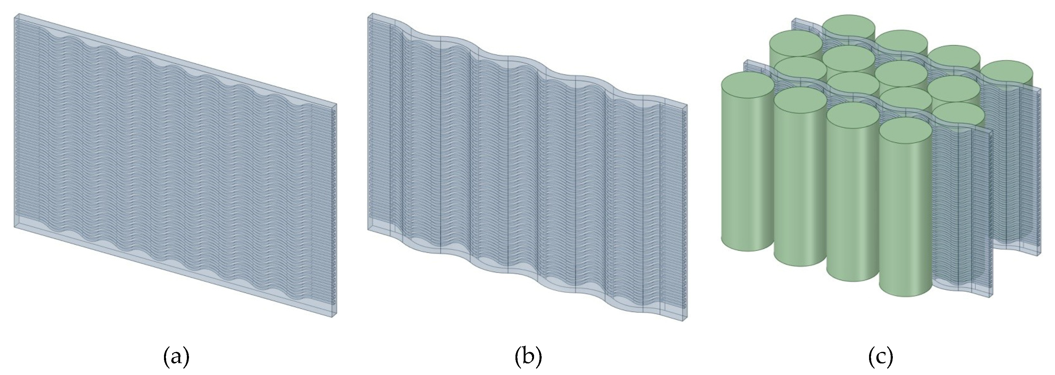
Figure 2.
(a) Ordinary wavy microchannel; (b) Bidirectional curved wavy microchannel; (c) x-z plane diagram of ordinary wavy microchannel and bidirectional curved wavy microchannels; (d) x-y plane diagram of bidirectional curved wavy microchannel with A2 = 2 mm and λ2 = 12 mm; (e) Inlet cross section.
Figure 2.
(a) Ordinary wavy microchannel; (b) Bidirectional curved wavy microchannel; (c) x-z plane diagram of ordinary wavy microchannel and bidirectional curved wavy microchannels; (d) x-y plane diagram of bidirectional curved wavy microchannel with A2 = 2 mm and λ2 = 12 mm; (e) Inlet cross section.
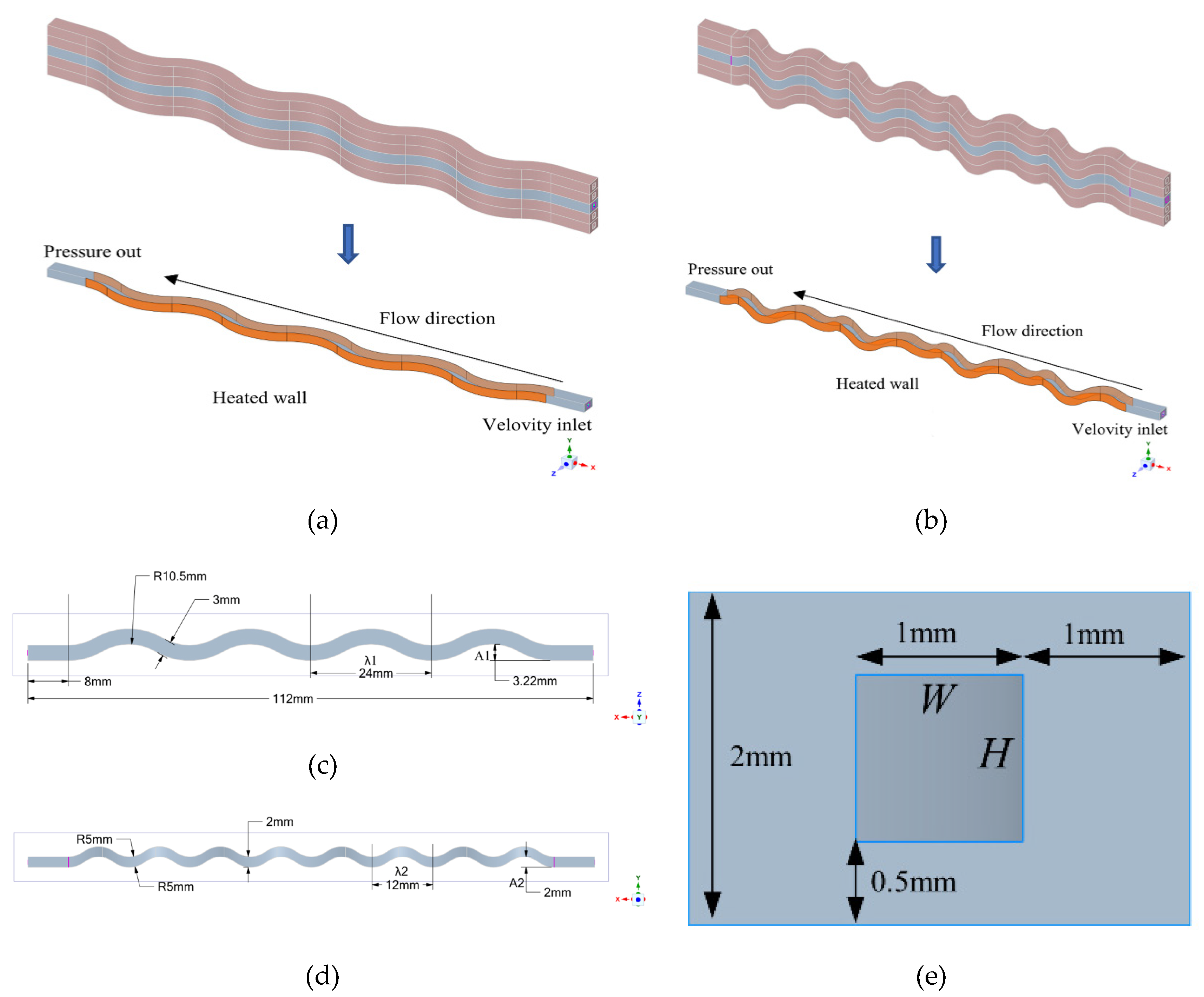
Figure 3.
Grid independence test.

Figure 4.
Comparison of present computational model with Sui et al. [6] experimental results (a) Nusselt number and (b) friction factor.
Figure 4.
Comparison of present computational model with Sui et al. [6] experimental results (a) Nusselt number and (b) friction factor.
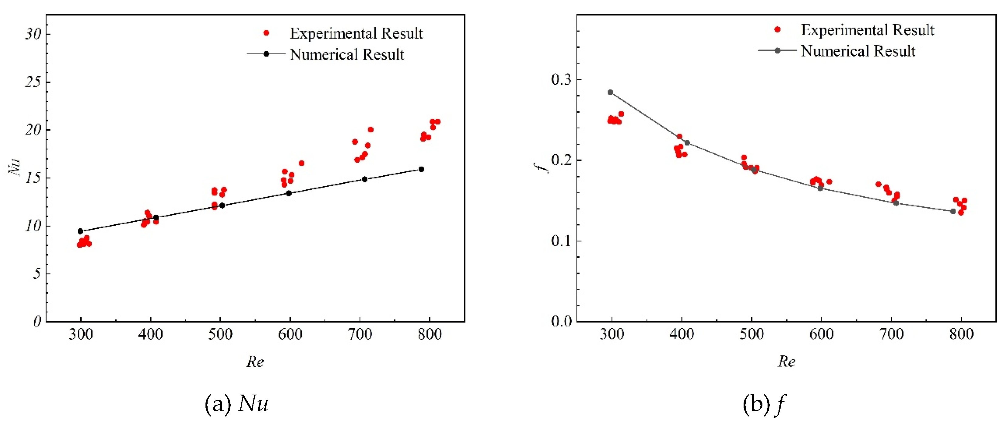
Figure 5.
The distributions of flow velocity and static pressure difference in the two channels are illustrated.
Figure 5.
The distributions of flow velocity and static pressure difference in the two channels are illustrated.
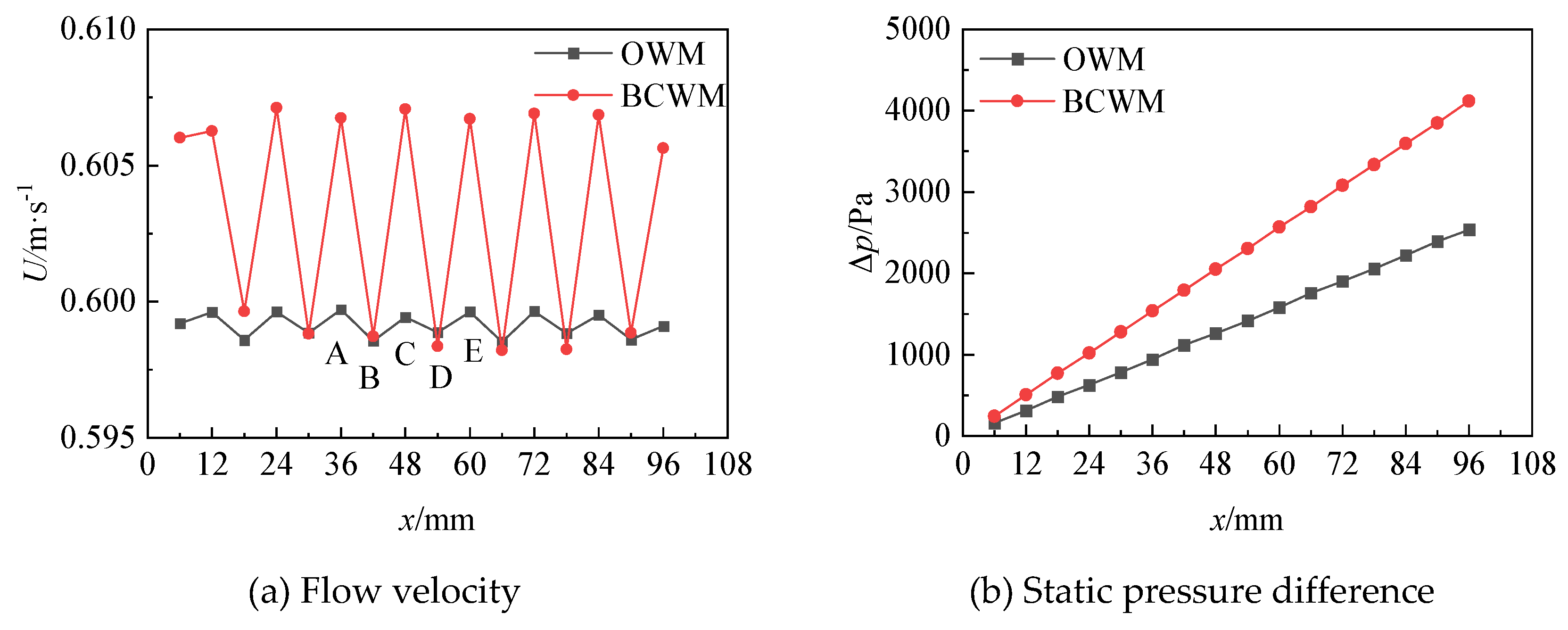
Figure 6.
Schematic diagram of the cross-sectional positions.
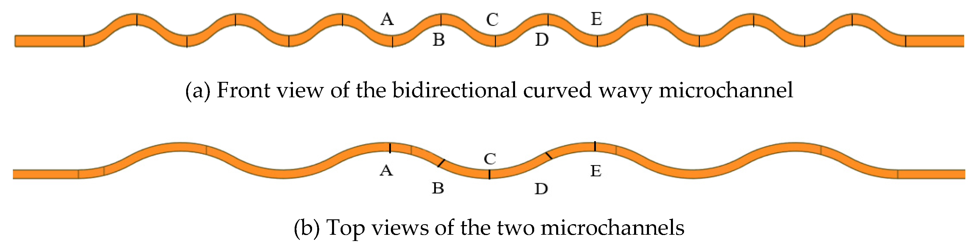
Figure 7.
Pressure contours of the two channels.
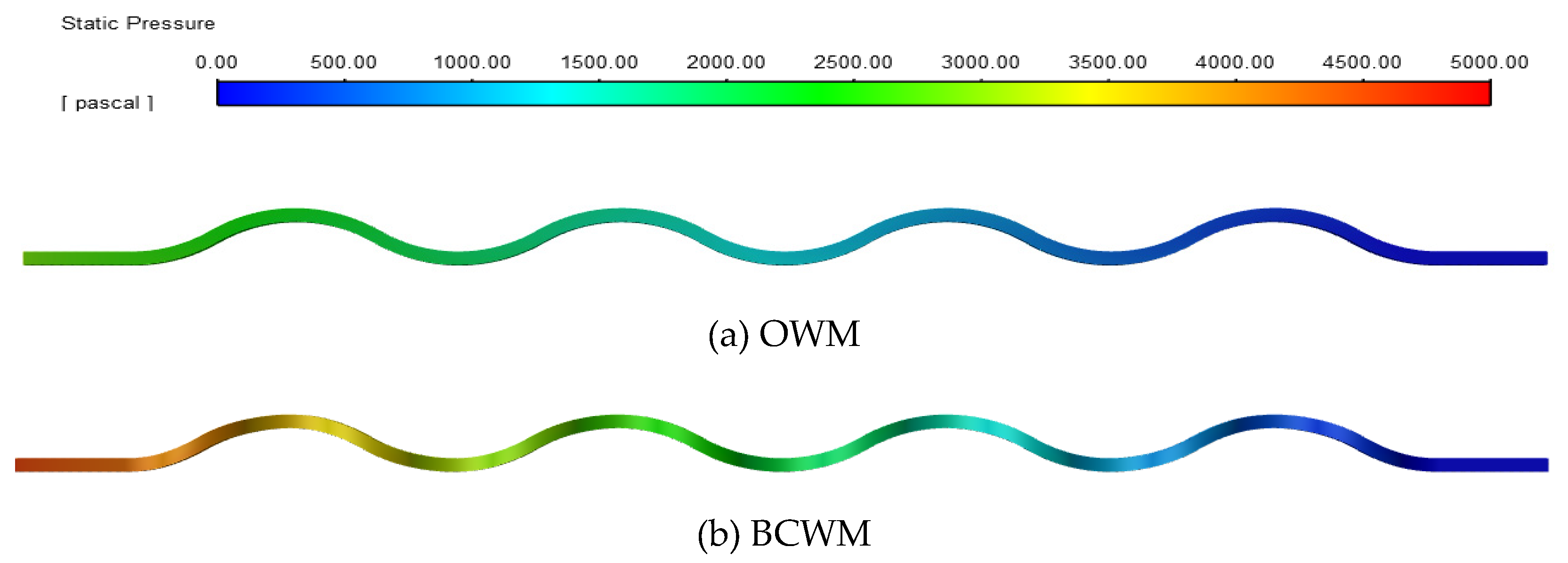
Figure 8.
Distributions of fluid temperature, wall temperature, and Nusselt number for the two channels.
Figure 8.
Distributions of fluid temperature, wall temperature, and Nusselt number for the two channels.
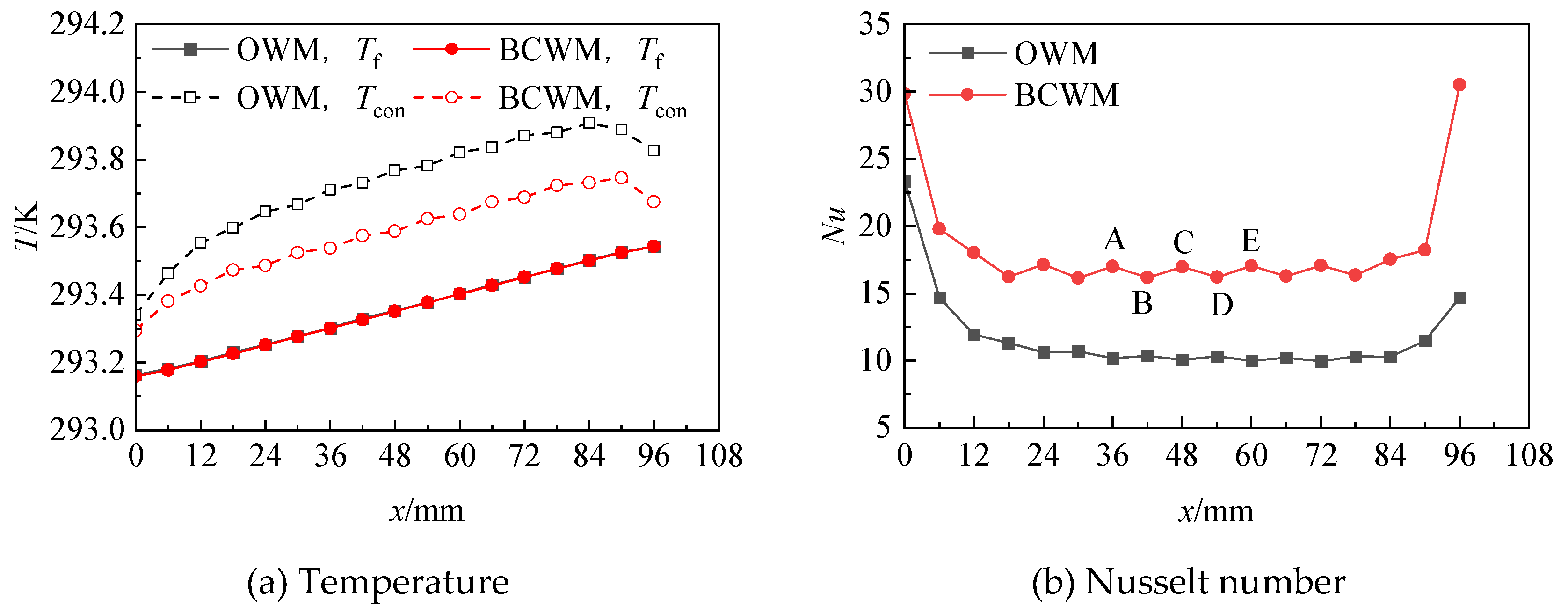
Figure 9.
Coupled wall temperature contours of the two channels.
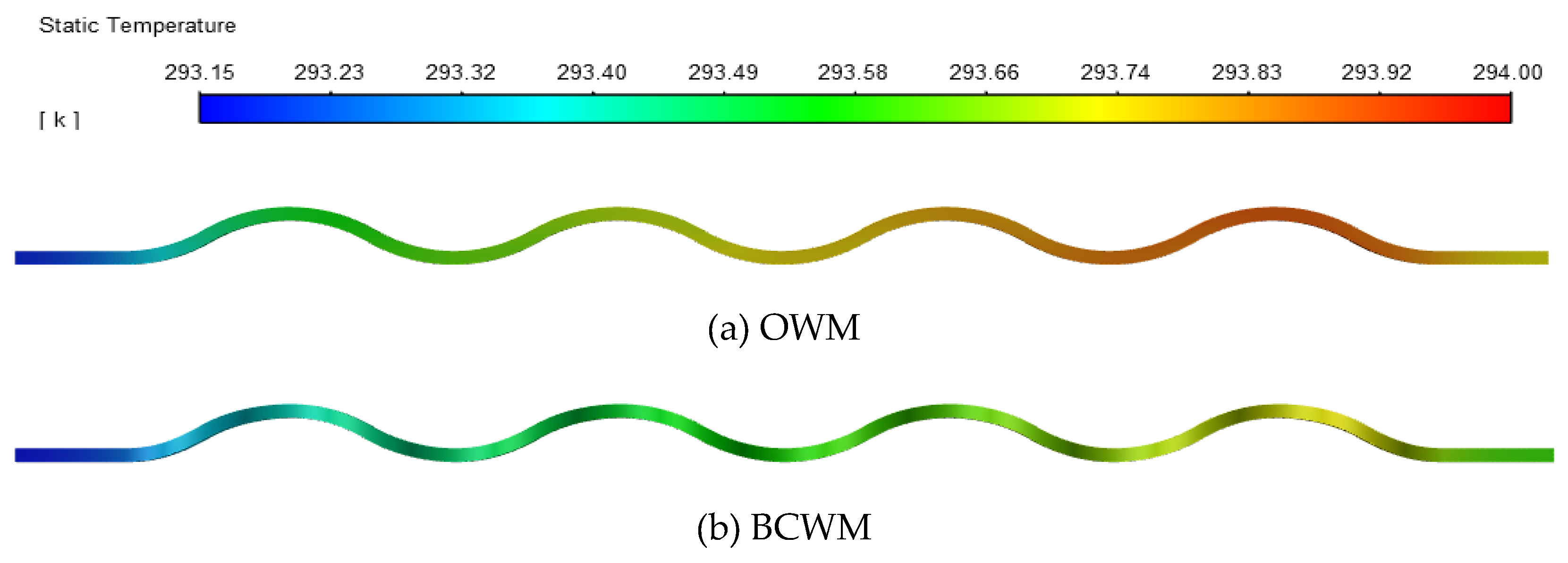
Figure 10.
Front views of the fluid domains of the bidirectional curved wavy microchannels with different wavelengths λ2.
Figure 10.
Front views of the fluid domains of the bidirectional curved wavy microchannels with different wavelengths λ2.
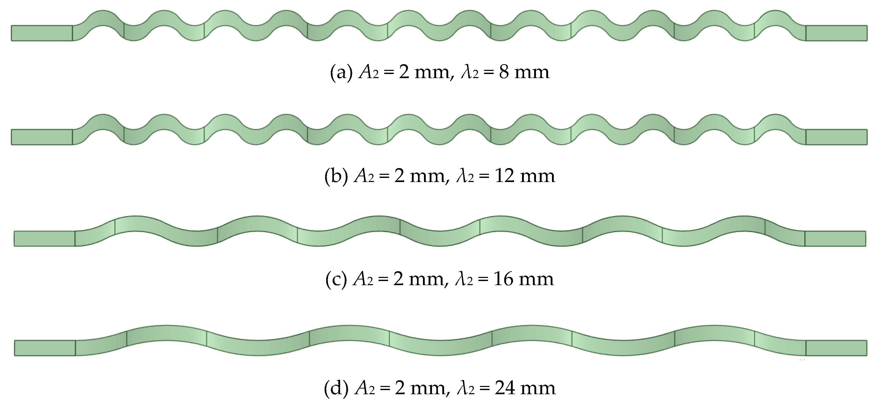
Figure 11.
Thermo-hydraulic performance of bidirectional curved wavy microchannels with the same
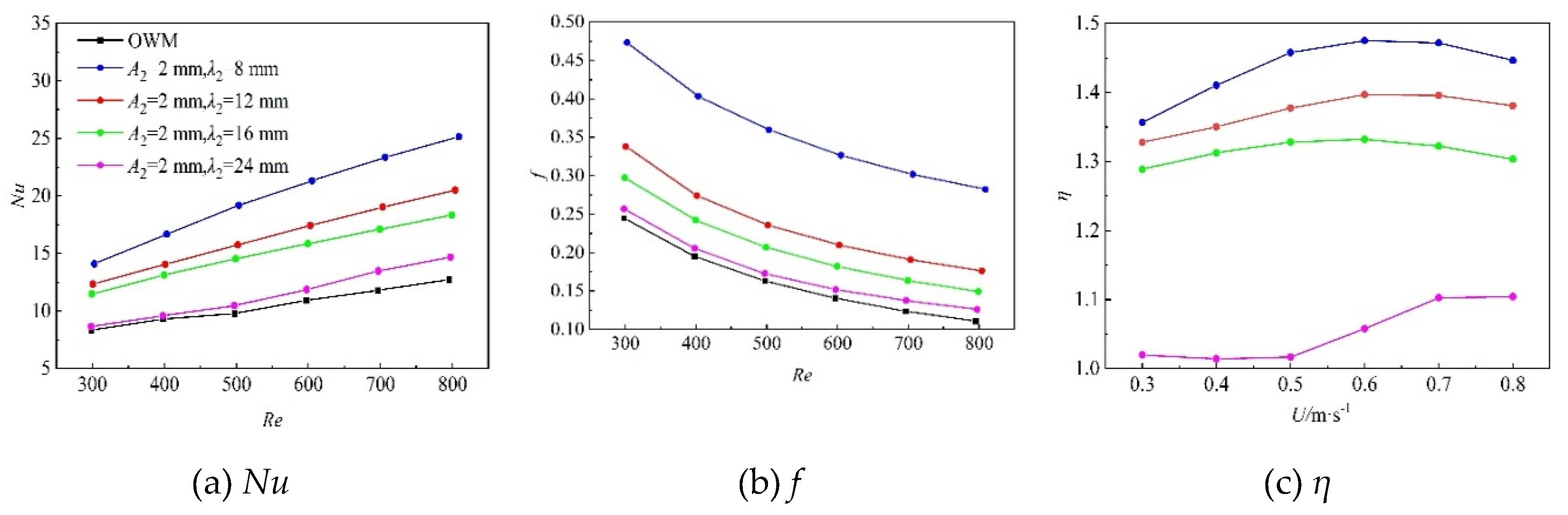
Figure 12.
Front views of the fluid domains of the bidirectional curved wavy microchannels with the same wavelength-to-amplitude ratio γ2.
Figure 12.
Front views of the fluid domains of the bidirectional curved wavy microchannels with the same wavelength-to-amplitude ratio γ2.
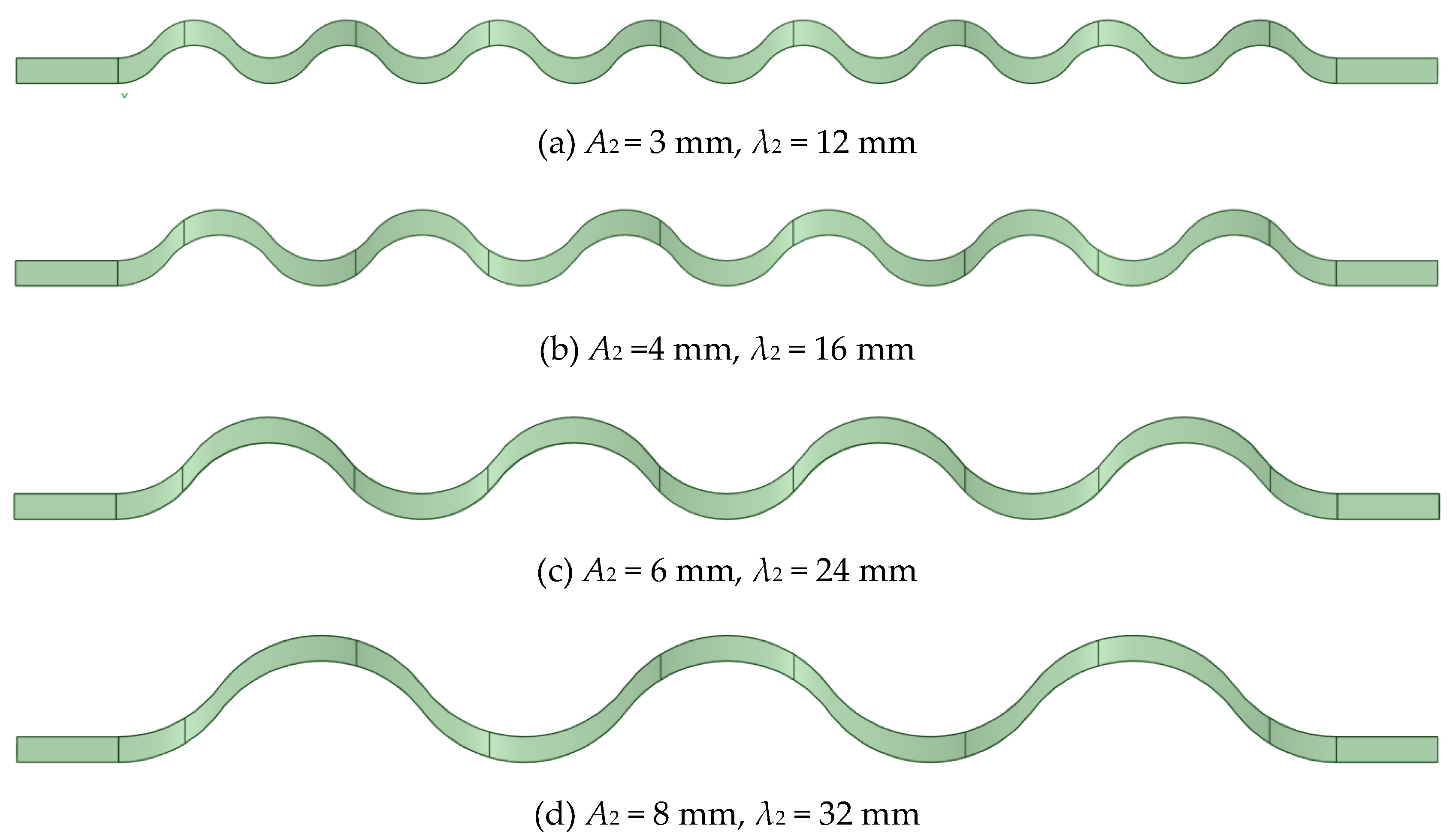
Figure 13.
Thermo-hydraulic performance of bidirectional curved wavy microchannels with the same γ2: (a) Nusselt number, (b) friction factor and (c) comprehensive performance factor.
Figure 13.
Thermo-hydraulic performance of bidirectional curved wavy microchannels with the same γ2: (a) Nusselt number, (b) friction factor and (c) comprehensive performance factor.
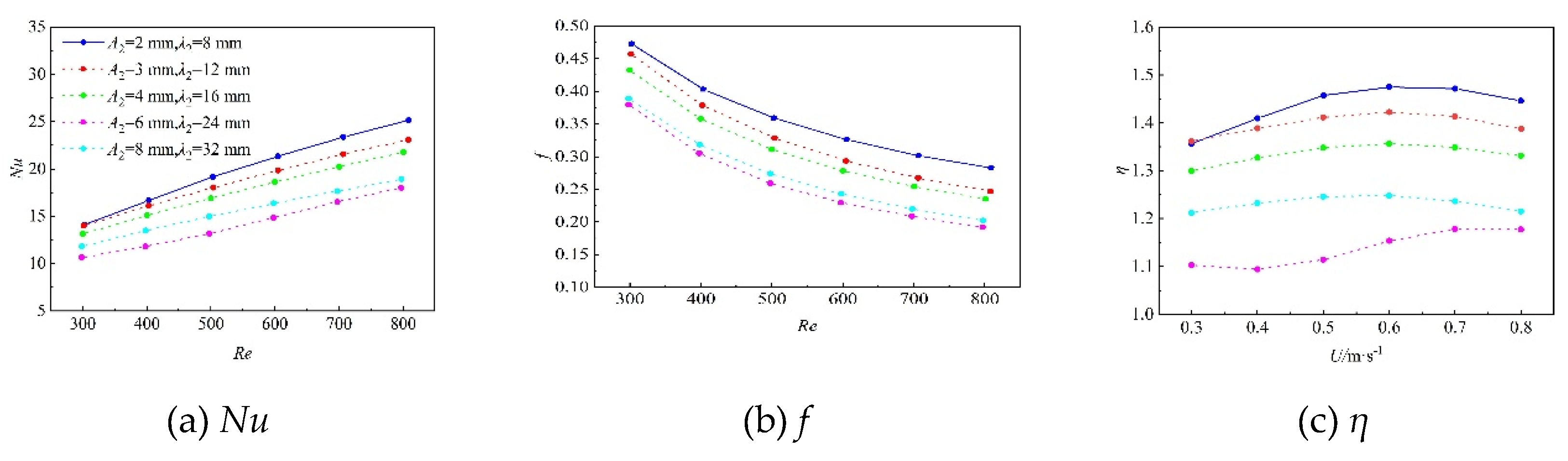
Figure 14.
Thermo-hydraulic performance of bidirectional curved wavy microchannels with the same λ2: (a) Nusselt number, (b) friction factor and (c) comprehensive performance factor.
Figure 14.
Thermo-hydraulic performance of bidirectional curved wavy microchannels with the same λ2: (a) Nusselt number, (b) friction factor and (c) comprehensive performance factor.
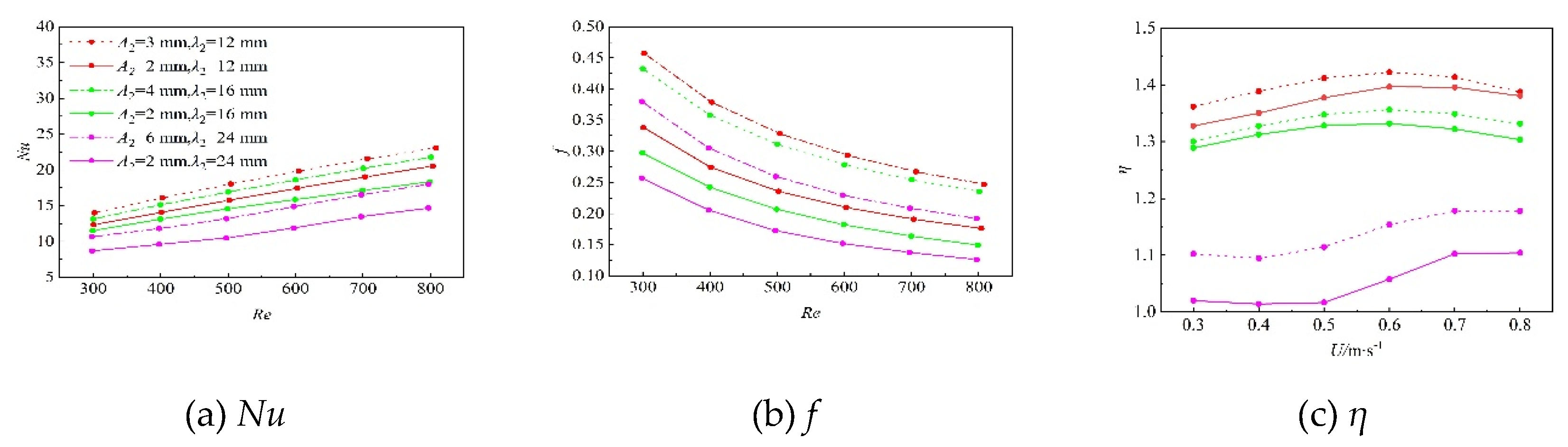
Figure 15.
The discrepancy of Nu and Nu* for the bidirectional curved wavy microchannel with A2 = 2 mm and λ2 = 12 mm and the ordinary wavy microchannel.
Figure 15.
The discrepancy of Nu and Nu* for the bidirectional curved wavy microchannel with A2 = 2 mm and λ2 = 12 mm and the ordinary wavy microchannel.
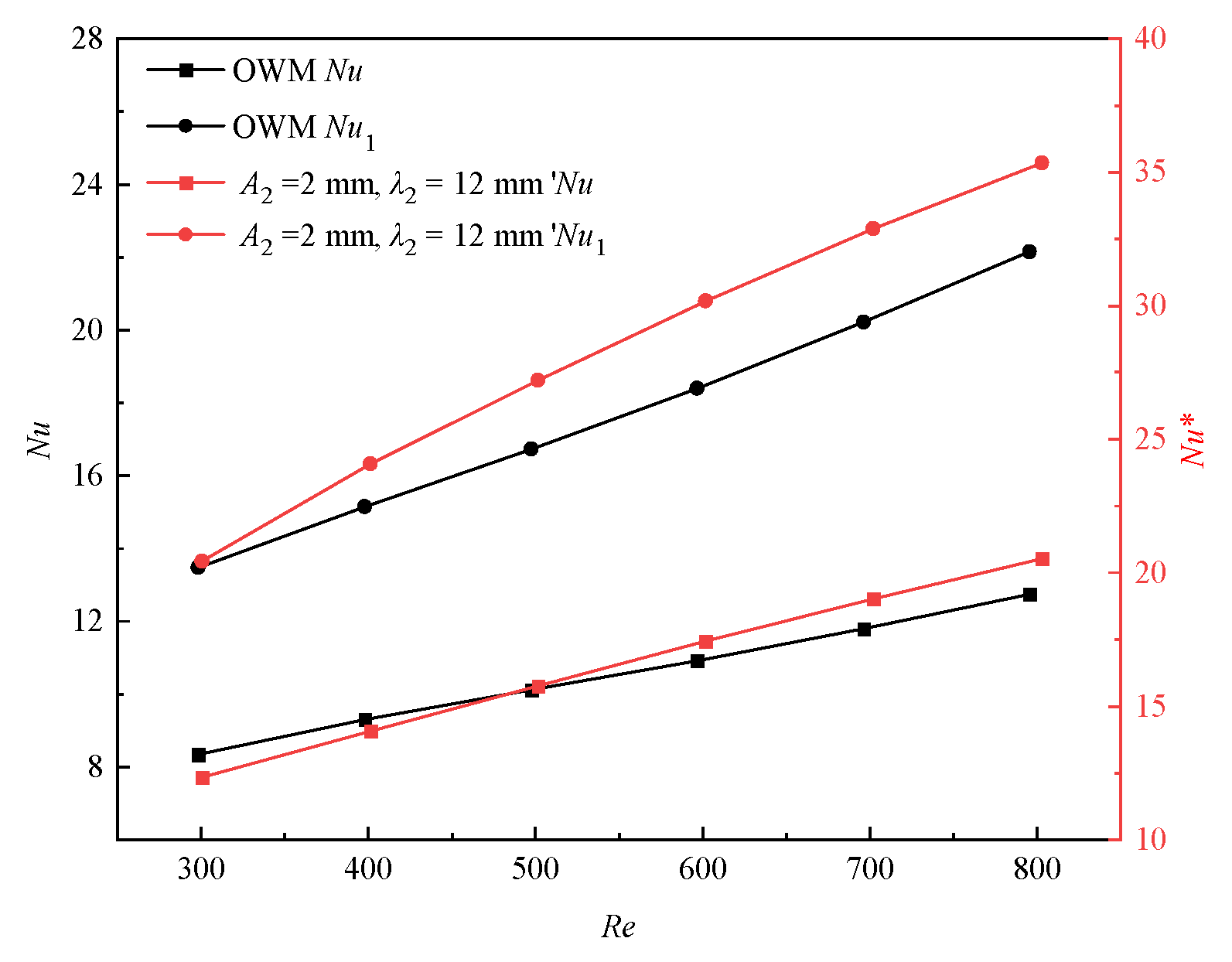
Figure 16.
Secondary flow intensity distributions of the two channels.
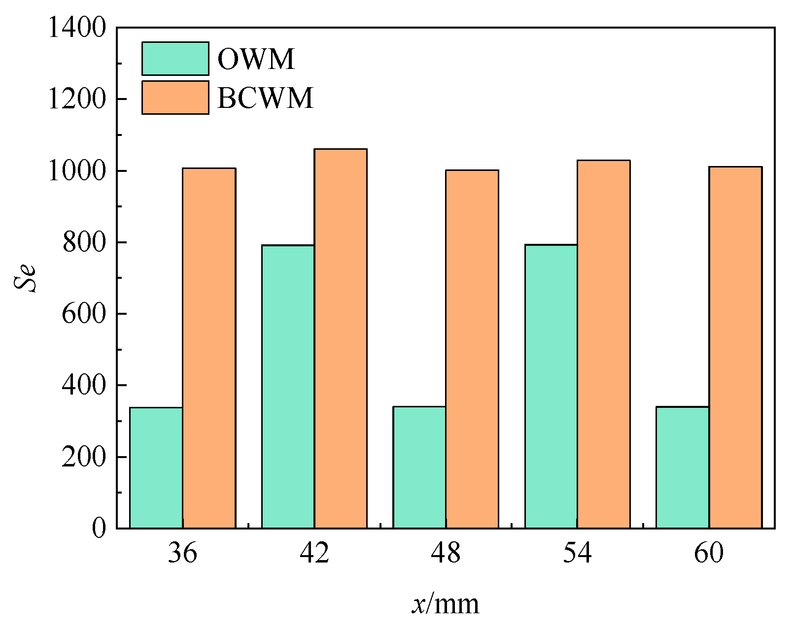
Figure 17.
Non-dimensional entropy generation rate analysis of microchannels with different types as a function of Reynolds number. (a) heat transfer entropy generation rate, (b) fluid flow entropy generation rate and (c) total entropy generation rate.
Figure 17.
Non-dimensional entropy generation rate analysis of microchannels with different types as a function of Reynolds number. (a) heat transfer entropy generation rate, (b) fluid flow entropy generation rate and (c) total entropy generation rate.
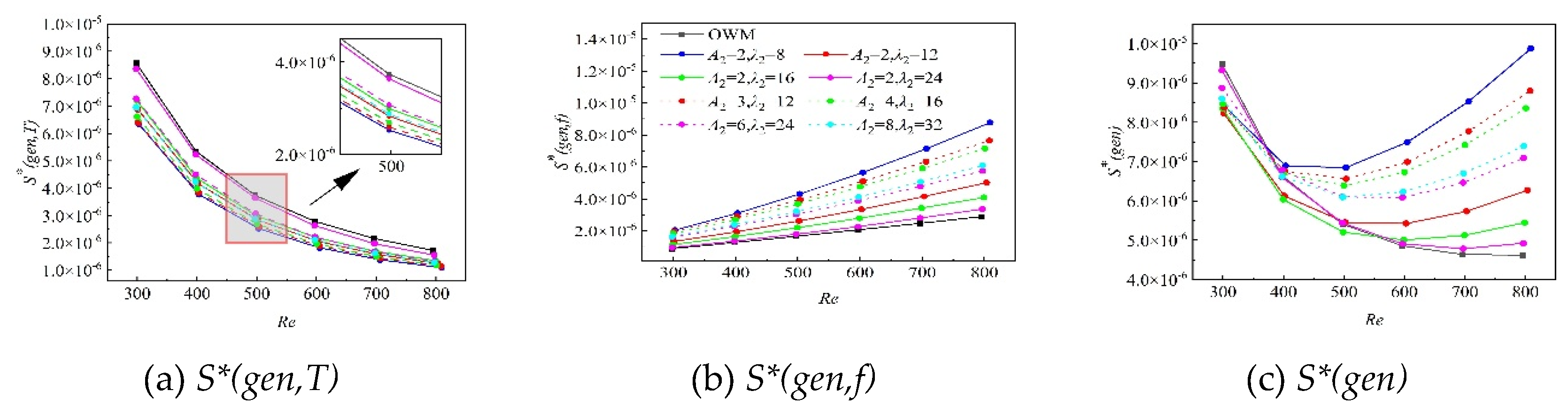

Table 1.
Comprehensive performance factors (η) of different bidirectional curved wavy microchannels at different inlet velocities.
Table 1.
Comprehensive performance factors (η) of different bidirectional curved wavy microchannels at different inlet velocities.
| /mm | 2 | 2 | 2 | 2 | 3 | 4 | 6 | 8 |
| /mm | 8 | 12 | 16 | 24 | 12 | 16 | 24 | 32 |
| 0.3 m/s | 1.36 | 1.33 | 1.29 | 1.02 | 1.36 | 1.30 | 1.10 | 1.21 |
| 0.4 m/s | 1.41 | 1.35 | 1.31 | 1.01 | 1.39 | 1.33 | 1.09 | 1.23 |
| 0.5 m/s | 1.51 | 1.38 | 1.32 | 1.06 | 1.41 | 1.34 | 1.11 | 1.24 |
| 0.6 m/s | 1.46 | 1.39 | 1.33 | 1.06 | 1.42 | 1.36 | 1.15 | 1.25 |
| 0.7 m/s | 1.47 | 1.39 | 1.32 | 1.10 | 1.41 | 1.35 | 1.19 | 1.27 |
| 0.8 m/s | 1.44 | 1.38 | 1.30 | 1.10 | 1.39 | 1.33 | 1.18 | 1.21 |
Disclaimer/Publisher’s Note: The statements, opinions and data contained in all publications are solely those of the individual author(s) and contributor(s) and not of MDPI and/or the editor(s). MDPI and/or the editor(s) disclaim responsibility for any injury to people or property resulting from any ideas, methods, instructions or products referred to in the content. |
© 2026 by the authors. Licensee MDPI, Basel, Switzerland. This article is an open access article distributed under the terms and conditions of the Creative Commons Attribution (CC BY) license.
Copyright: This open access article is published under a Creative Commons CC BY 4.0 license, which permit the free download, distribution, and reuse, provided that the author and preprint are cited in any reuse.


