

Submitted:
22 May 2026
Posted:
22 May 2026
You are already at the latest version
Abstract
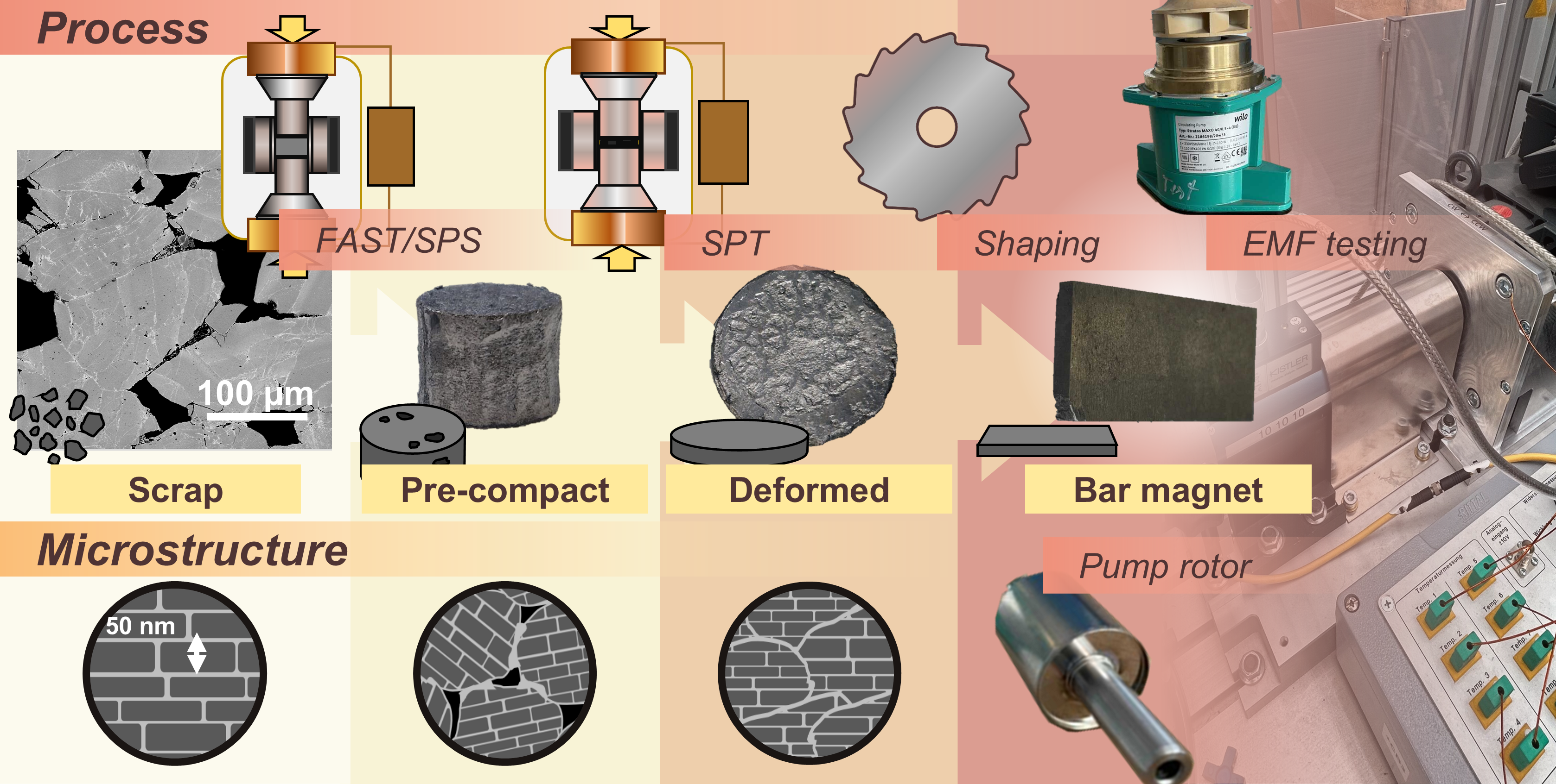
The particular microstructure of hot-deformed Nd-Fe-B magnets leads to difficulties in finding a direct recycling route. In this work, a combination of field assisted sintering technology/spark plasma sintering (FAST/SPS) and spark plasma texturing (SPT) are used as pre-compaction and deformation techniques, respectively, for the consolidation of crushed, hot-deformed Nd-Fe-B scrap. Field assisted sintering has the unique advantage of maintaining fine microstructures during material densification, making it an ideal candidate for direct recycling of this material. Recycled magnets, made from 100 wt% crushed magnet scrap, were able to achieve energy products of over 200 kJ m-3 after FAST/SPS pre-compaction and SPT deformation. These recycled magnets could then be smoothed and cut to the size of industrial bar magnets for testing in the motor of a water pump. When tested, the recycled magnets could achieve 95% of the electromotive force compared to industrial standard magnets.
Keywords:
recycling
; field assisted sintering
; permanent magnets
; functional materials
; circular economy
; rare earth elements
1. Introduction
Currently, the strongest known commercially available magnets are Nd-Fe-B magnets, boasting a theoretical energy product, (BH)max, of 512 kJ m-3. This high energy product has led to their usage in a huge variety of market applications, ranging from consumer electronics to electric vehicles to wind turbines [1,2,3]. Specific properties of these magnets, such as temperature resistance, are tuned through the introduction of heavy rare earth elements (REEs), like Dy and Tb [4,5]. While the demand for Nd-Fe-B magnets continues to grow, the geographic and geological availability of mined REEs remains limited. Because profitable extraction of REEs is limited to a few regions worldwide, geopolitical dependencies and supply risks can arise. Recycling Nd-Fe-B magnets could mitigate potential supply risk in the mid-term, and a variety of recycling techniques have been considered for extracting valuable elements from Nd-Fe-B magnets in e-waste, such as pyrometallurgy, hydrometallurgy, solvent-based and kinetics-based techniques [6,7,8,9,10,11,12]. Direct recycling of Nd-Fe-B has also been of interest, as it does not involve chemical modification of the Nd-Fe-B magnets. However, the application of direct recycling for hot-deformed Nd-Fe-B magnets has been limited so far.
There are multiple preparation routes for Nd-Fe-B magnets. Two routes involve producing Nd-Fe-B magnets with 100 wt% magnetic material, with the first being sintering of Nd-Fe-B. Sintered Nd-Fe-B magnets are formed through compacting microcrystalline Nd-Fe-B powders into a green body, exposing that green body to an external magnetic field during compaction, then freely sintering the green body into a dense part [13]. Sintered Nd-Fe-B is capable of being directly recycled via hydrogen-decrepitation-desorption-recombination (HDDR), a process in which H2 reacts with the RE-rich phase, leading to a volume expansion in the grain boundary phase. This volume expansion leads to cracks along the grain boundaries, followed by the decrepitation of the magnet into a coarse powder [14,15,16]. This magnetic powder can then be recycled into a polymer bonded magnet via injection molding or cold-pressing, or it can be re-sintered into a new sintered magnet [17,18,19]. Sintering recycled powder leads to a decrease in magnetic performance with each subsequent recycling, most probably due to the oxidation of the grain boundary layer, dampening its ability to form a liquid phase during sintering. Pure Nd would need to be added to the recycled powder to mitigate this effect [15].
The second production route for Nd-Fe-B magnets with 100 wt% magnetic material is hot deformation. Hot deformation starts with melt-spun nanocrystalline Nd-Fe-B powder, which is hot-compacted into a pre-form. At this stage, the grain boundary is melted, and anisotropic grain growth begins. This pre-form is then hot-deformed at 800 °C to thermomechanically align the crystal grains and increase the grain aspect ratio (targeting a lateral diameter of 200-500 nm, and a thickness of 20-50 nm) [20,21]. Simultaneously, the c-axis of the Nd-Fe-B grains rotate parallel to the uniaxial pressing direction. It is possible to perform HDDR on hot-deformed magnets to produce a powder. However, recycling of this powder either via sintering or repeated hot deformation will lead to a decrease in magnetic performance, as the grains will expand beyond their target aspect ratio due to the high processing temperatures [22]. HDDR powders also contain coarser grains, leading to greater deformation resistance during hot deformation when compared to nanocrystalline powder and a higher risk of samples cracking [23,24]. The texture of a sample made from repeated hot-deformed HDDR powder is also suboptimal [25,26,27]. Recycling hot-deformed Nd-Fe-B powder via polymer bonding is possible, but decreasing the volume fraction of magnetic material through the introduction of a binder will decrease the overall magnetic performance. The option of re-melting hot-deformed magnets exists as well, such as through melt-spinning new nanocrystalline Nd-Fe-B flakes to restart the hot deformation process from the beginning. While this option is also considered “short loop” and comparable to direct recycling, it involves high energy input for melting the material [14].
In an ideal case, the direct recycling of hot-deformed Nd-Fe-B scrap would accomplish two main goals:
- Full densification, so the entire magnet volume consists of magnetic material
- Microstructure control, avoiding disturbance to the already established anisotropic and fine-tuned grain size
A possible method of directly recycling hot-deformed Nd-Fe-B scrap is through electric current assisted sintering (ECAS). In ECAS processes, the application of an electric current leads to Joule heating within the material bulk. ECAS is often paired with the application of uniaxial pressure, which also improves the densification and development of the microstructure. Several ECAS methods have been investigated for the processing of Nd-Fe-B magnets in general, such as electro discharge sintering (EDS) [28,29] and flash spark plasma sintering (flash SPS) [30]. Flash SPS in particular was investigated for its parallels to hot deformation while still being capable of tuning crystallographic texture of Nd-Fe-B on the nanoscale [31,32]. Flash SPS showed promising results in the processing of anisotropic magnetic scrap into new magnets, but it suffered from samples cracking at their edges and the inability to generate a 100 wt% recycled Nd-Fe-B magnet with a (BH)max higher than 200 kJ m-3 [33].
For better control over the integrity of sample edges, another ECAS technique was considered, known as spark plasma texturing (SPT). SPT behaves in a similar way to hot deformation, in which a dense or semi-dense part is deformed to a final shape. In the case of SPT, though, the heat necessary for the hot deformation is generated through Joule heating. In this work, SPT is combined with the established field assisted sintering technology/spark plasma sintering (FAST/SPS) as a hot compaction step, necessary prior to SPT. The FAST/SPS process works through compacting powder in a conductive tool made of two punches and a die with uniaxial pressure. Simultaneously, direct current flow heats the powder and the die by Joule heating. The speed at which Joule heating occurs allows for fast heating rates, leading to quick densification. This helps to avoid long dwell times at high temperatures, which would lead to excessive grain growth in anisotropic Nd-Fe-B.
FAST/SPS has been explored as an alternative to hot compaction by many authors, who have demonstrated its capabilities in densification of Nd-Fe-B in numerous studies [24,26,34,35,36,37,38,39,40]. However, single-stage FAST/SPS for hot compaction does not lead to texture development in Nd-Fe-B. The introduction of SPT as a deformation stage makes up for this. In SPT, a self-supporting pre-form is placed within a die of a larger diameter size. The same application of Joule heating and uniaxial pressure is applied, as with FAST/SPS. Rather than just compacting a powder, though, the introduced heat reduces flow stress, and the application of a uniaxial pressure leads to a stress larger than the flow stress, leading to a plastic deformation of the pre-form. This deformation ideally transforms the morphology of isotropic grains into platelets or forces anisotropic grains to rotate, causing their c-axes to be parallel to the pressing direction. If executed correctly, SPT would lead to a brick-wall-like texture of Nd2Fe14B grains surrounded by a thin Nd-rich grain boundary layer. SPT has been successfully implemented to generate anisotropic Nd-Fe-B magnets from commercial melt-spun MQU-F powder [41]. SPT has yet to be considered for direct recycling of Nd-Fe-B magnets thus far.
In this work, SPT is explored as a substitute hot deformation method for recycling anisotropic Nd-Fe-B scrap. Hypothetically, SPT could allow for the rotation of already anisotropic grains to a newly introduced orientation through uniaxial pressure without excessive grain growth, due to its quick heating time. In this case, the Nd-rich grain boundary phase would be partially or fully liquefied due to a liquid phase beginning to form at 665 °C [42]. Then, the application of pressure is expected to cause the Nd2Fe14B grains to rotate. While the presence of a liquid phase could imply mass transfer for grain growth, it is supposed that the short duration of the deformation at temperatures above 600 °C will mitigate this effect. Figure 1 displays the overview of the process flow as applied in this work, including the hypothetical and ideal microstructure of the Nd-Fe-B samples through various processing stages.
2. Materials and Methods
2.1. Starting Powders
Two magnetic powders were selected for processing. The first was Magnequench MQU-F melt-spun powder (Neo Performance Materials, Canada) (batch number B55557), which is a commercially available melt-spun Nd-Fe-B powder used in magnet production. This powder is referred to “MQ”. In this work, MQ was used solely in mixes with recycled powder to enhance magnetic performance. The second was a recycled powder consisting of crushed out-of-spec Nd-Fe-B magnets from the company WILO SE (Germany) crushed by Less Common Metals (UK) (LCM Batch J9348/FP33302 delivered by WILO SE). The powder fraction delivered was of a particle size <200 μm. From this batch, the fraction <180 μm was sieved off, leaving a powder of the particle size range 180-200 μm. This was done to eliminate powder fractions that were rich in oxygen contamination, which would have degraded the final magnetic performance [1]. This powder is referred to as “LCM” in this work. A mix consisting of 75 wt% LCM, 25 wt% MQ was prepared through mixing for 10 minutes via tumble mixer and is referred to as “L75_M25” in this work.
2.2. Pre-Compaction by FAST/SPS
Compaction of powders into a pre-form was performed in a FAST/SPS device (HP-D5, FCT Systeme GmbH, Rauenstein, Germany), and all experiments were performed under vacuum. 30 g of magnet powder was pre-compacted into a graphite die (SIGRAFINE R7710, SGL Carbon GmbH, Germany) with an inner diameter of 20 mm. Specialized graphite punches, which were cut to be shorter than normal, were used to compensate for the extra height from the 30 g of material. This allowed the die set-up to fit properly into the HP-D5 device. For tool preservation and protection, a graphite foil of 0.38 mm (SIGRAFLEX, SGL Carbon GmbH, Germany) was used in the inner circumference of the die and between the punches and powder. In order to achieve stable Nd-Fe-B compacts with varying porosity, the powder was heated to a maximum temperature of 500, 600, or 700 °C with a heating rate of 100 K min-1 (Table 1). At 500 °C (parameter set C1), dwell was increased to 120 seconds due to success with this dwell time for flash SPS samples in the work by Maccari et al. [2]. A shorter dwell time of 60 seconds was used for higher temperatures to avoid excessive grain growth at the pre-compaction stage. A constant load of 16 kN, resulting in a nominal uniaxial stress of 50 MPa, was applied throughout the procedure. One series was an exception to these experimental parameters, shown as C4 in Table 1. This series consisted of samples made from 35 g of LCM rather than 30 g, as it allowed for a taller sample after SPT with more flexibility for smoothing the faces of the magnet after deformation. C4 pre-compaction was performed in a ∅ 20 mm titanium-zirconium-molybdenum alloy (TZM) die with TZM punches (Plansee, Reutte, Austria) using the same parameters as C2. However, in this case, sintering was performed in the hybrid FAST/SPS device (H-HP-D25 SD/FL/MoSi, FCT Systeme GmbH, Germany) due to the increased height of the die and punches.
2.3. Spark Plasma Texturing
SPT experiments were performed to generate clean, crack-free edges in the Nd-Fe-B samples. SPT experiments were done using TZM dies and punches (Plansee, Reutte, Austria), as these could withstand much higher pressures than graphite tools. A pre-compacted ∅ 20 mm Nd-Fe-B sample was placed in the center of the ∅ 40 mm TZM die. The inner diameter of the TZM tool was lined with a 0.38 mm thick graphite foil, and the punches and ∅ 20 mm Nd-Fe-B sample were separated by ∅ 40 mm disks of the same foil (type SIGRAFLEX, SGL Carbon GmbH, Germany). The TZM tool containing the ∅ 20 mm compact centered in the die was then mounted in the hybrid FAST/SPS device (H-HP-D25 SD/FL/MoSi, FCT Systeme GmbH, Germany). The SPT cycle was then initiated, which consisted of the following steps:
- A starting force of 10 kN was applied to the ∅ 20 mm pre-compact. Temperature was increased to 800 °C at a rate of 100 K min-1.
- Once the target temperature of 800 °C was achieved, the maximum force of 126 kN (100 MPa on ∅ 40 mm) was applied over a duration of 30 seconds, leading to an applied increase of stress with a rate of 3.33 MPa s-1.
- Maximum nominal stress and temperature were subsequently held for an additional 10 seconds.
- After the dwell period, the power pulse is switched off and the sample is allowed to cool
This parameter set was chosen based on previous SPT experiments, which had shown that deformation needed to occur in a quick yet controlled fashion to generate favorable magnetic behavior. Deformation at a higher rate often caused the Nd-rich grain boundary phase to pool in pores, leading to a phase segregation that negatively influenced magnetic performance. Holding the maximum pressure for several seconds after full application also showed favorable influence. Diagrams of both set-ups for FAST/SPS pre-compaction and SPT deformation are shown in Figure 2.
2.4. Analysis of Density, Microstructure, and Magnetic Performance
Density of the samples was calculated via geometric measurements, with relative density compared to considered Nd-Fe-B density of 7.55 g cm-3. Magnetic characterization was performed with the Permagraph C-300 system (MAGNET-PHYSIK Dr. Steingroever GmbH, Köln, Germany) after previous magnetization in a pulsed field. An ∅ 8.5 mm disk was cut from a sample’s bulk in order to be tested. Permagraph measurements were performed by WILO SE. For scanning electron microscopy (SEM) of pre-compacted and deformed samples, a Zeiss Gemini 450 (Carl Zeiss AG, Germany) was used. All SEM images were taken with a back-scattered electron (BSE) detector. Pre-compacted samples were analyzed with an acceleration voltage of 15 kV.
2.5. Formation of Demonstrator Magnets for Use in Water Pumps
After SPT, the recycled magnets had rough faces that needed to be smoothed. This was performed at Ruhr-Universität Bochum via cup grinding to achieve a final magnet height of 3.1 mm. From then, the smoothed magnets were sent to WILO SE to be cut into bars of 33.5 x 16.2 mm via electro discharge machining. Four cut magnets were then tested in a rotor designed for a Stratos MAXO 40/0.5-4 Circulating Pump (WILO SE, Dortmund, Germany). The electromotive force (EMF) was measured at a rotational speed of 4000 RPM. This was compared with a rotor rotating at the same speed containing standard hot-deformed Nd-Fe-B magnets produced by WILO. The EMF measurement was carried out by installing a stator of the pump motor into the test setup and then driving the rotor via the drive unit of the test setup. A torque measurement shaft was connected between the rotor and the drive unit, and the induced voltage within the stator winding was measured. Measurements from the stator are transmitted to a 3-channel storage oscilloscope.
3. Results and Discussion
3.1. Behavior of Pre-Compacted Pellets
The goal of the variation of pre-compaction temperatures was to increase the resistance to the applied uniaxial stress during the deformation stage of SPT, as low-density forms could collapse. Pre-compaction at 500 °C (C1) was chosen due to its similarity to samples deformed via flash SPS in a previous study [1], while pre-compaction at 700 °C (C3) would be closer in temperature to the most successful SPT samples made from commercial material in a previous study [3]. 600 °C (C2) was chosen as a mid-point. 700 °C may have been favorable for isotropic starting powders, but this temperature could be detrimental to anisotropic powders. The wetting-phase transition of the Nd-rich grain boundary phase is roughly 690 °C, with the eutectic phase temperature being 665 °C [4,5]. The wetting-phase transition refers to the beginning temperature at which the contact angle between a liquid phase and a solid phase is zero, leading to a continuous liquid phase at the grain boundaries. Increasing the temperature from the wetting-phase transition increases the percentage of Nd2Fe14B grains that are fully wetted by the Nd-rich liquid phase, with a temperature of 690 °C leading to roughly 15% of all grain boundaries in an Nd-Fe-B system being wetted [4]. Due to the occurrence of thermal gradients and hot-spots possible under FAST/SPS conditions, C2 likely causes points inside the bulk to reach temperatures significantly over 600 °C. Therefore, more liquid phase is expected to be present in C3 and C2 than in C1, encouraging excessive grain growth at the pre-compaction stage. Evidence of some Nd-rich phase segregation can be seen in Figure 3, with the LCM_C2 and LCM_C3 pre-compacted samples displaying some larger, bright Nd-rich regions when compared to LCM_C1. In LCM_C1, primarily, powder particles are connected by weak sintering necks, but the indication of Nd-rich phase segregation is not as prevalent. The greater presence of a partially liquid phase may have helped in the densification of LCM_C2 and LCM_C3, as their higher sintering temperatures led to relative densities 10-20% higher than that of LCM_C1. In the higher magnifications of Figure 3, two different BSE SEM magnifications of all three pre-forms are shown. In the lower magnification, distinct particles of crushed hot-deformed magnet are visible, having not fully consolidated. Inside these particles are the bands of melt-spun flakes that were used to generate the initial hot-deformed magnets, before they were crushed for recycling. In the higher magnification, the rectangular Nd2Fe14B grains, which are dark grey, are seen suspended in the lighter grey of the Nd-rich grain boundary phase. Irregular grain shapes occurred at expected regions, such as interfaces between these melt-spun flakes. Excessive grain growth, however, was not observed throughout the entirety of pre-compacted samples, even at the maximum temperature of 700 °C.
Table 2 lists the heights, diameters, and relative densities of all pre-forms made in this series. Of note, most samples have a diameter larger than the expected ∅ 20 mm. Tolerances of the graphite die often allowed for the diameters of the samples to be slightly larger than anticipated. However, LCM_C4 samples pushed the limit of these tolerances. As seen in Figure 4A, LCM_C4 pellets would experience a bowing effect during sintering, with wider diameters of the sample in contact with the punches and a smaller diameter towards the center. Likely, LCM_C1, LCM_C2, and LCM_C3 experienced a similar bowing, but the additional mass in LCM_C4 made the issue more prominent. The bowing could be attributed to the upper and lower portions of the sample receiving the most stress and deforming in response. It could also be due to wall friction, with a lower density in the middle of the sample leading to higher shrinkage. This bowing would not only warp the geometry of the sample, but it would also almost always cause cracking and breaking of the graphite dies upon extraction. Therefore, all LCM_C4 pre-compaction cycles were transferred to a TZM die and performed in the FCT HP- D25 device, as shown in Figure 4B.
As listed in Table 2, pre-compaction schemes C1, C2, and C3 were also performed on L75_M25 powder, while C4 was not. This is due to C4 only being used to produce 100 wt% recycled demonstrator magnets using the LCM powder.
3.2. Performance of SPT Deformed Samples
After pre-compaction, all pellets were subjected to the same deformation parameters via SPT. Small portions of these samples were then measured via Permagraph to determine their magnetic performances, which are listed in Table 3. SPT of LCM_C4 is not listed, as all LCM_C4_SPT samples were considered to be almost identical to LCM_C3_SPT, and all LCM_C4_SPT samples were to have their shape kept intact for use as demonstrator magnets.
The target values specified by WILO SE were HcJ > 1300 kA m-1 and Br ≥ 1.3 T. This would match the performance of their standard hot-deformed Nd-Fe-B magnets used in pump motors. According to DIN standard IEC 60404-8-1, this would correspond to an anisotropic, sintered rare earth-iron-boron (RE-Fe-B) magnet of designation REFeB 340/130 (code number: R7-1-14) [6]. In terms of Chinese commercial magnet grades, this corresponds to grades of roughly N38H, N40H, or N42H [7,8]. As seen in Table 3, no sample was capable of reaching these values. Of the samples made with 100 wt% recycled material, LCM_C3_SPT had the highest (BH)max of 277 kJ m-3. LCM_C2_SPT had a lower (BH)max (228 kJ m-3) but a better balance between coercivity and remanence (HcJ = 1049 kA m-1, Br = 1.24 T). The addition of 25 wt% MQ with the C2 pre-compaction (L75_M25_C2_SPT) further improved the performance, with significant improvements to both remanence and energy product (Br = 1.28 T, (BH)max = 313 kJ m-3). The addition of MQU-F likely offset some negative effects of excessive grain growth while contributing well-aligned grains of a target size, developed from the starting isotropic microstructure. L75_M25_C3_SPT only differed slightly from L75_M25_C2_SPT, having only slightly lower magnetic performance (HcJ = 1057 kA m-1, Br = 1.24 T, (BH)max = 295 kJ m-3). This could be attributed to some grain growth in the recycled material that happened during C3 pre-compaction.
Both samples pre-compacted with C1 have the lowest respective (BH)max. This is likely due to the samples collapsing during the SPT cycle. Rather than the denser C2 and C3 samples resisting the applied pressure and deforming to the larger diameter, C1 samples would crumble during the beginning of pressure application, causing an alarm in the FCT HP-D25 device and triggering immediate cessation of the program. When the TZM die was opened for examination, the C1 samples were found crushed back into powder. The weak bonds formed between particles and high porosity could not withstand the deformation pressure. Nevertheless, the SPT cycle was repeated with the C1 samples in this crushed state, and the magnetic performance values more reflect how the SPT parameters densified the powder once again. As the pressure of SPT was more utilized for compaction than deformation, grain alignment was not well realized in the C1 samples. This led to a lower Br and subsequent (BH)max relative to samples that experienced higher deformation during SPT. When comparing these values to commercial Nd-Fe-B magnet grades, the LCM series is roughly capable of reaching the DIN IEC 60404-8-1 designation of REFeB 290/80 in coercivity and remanence (HcJ = 800 kA m-1, Br = 1.23 T, (BH)max = 290 kJ m-3), while the addition of 25 wt% MQ fully achieves REFeB 290/80 designation, including energy product [6]. In terms of Chinese standard, LCM series can achieve a grade of roughly of N38 or N35, with the 25 wt% additional MQ increasing the grading to N40 [7,8].
SEM analysis of the samples indicates that some grain alignment was induced by the deformation, even with the recycled anisotropic LCM powder. This was not universal across the sample bulk. Figure 5 shows examples of well-aligned and poorly-aligned regions within the bulk. Both microstructures were taken from the area between “center” and “edge” as indicated in Figure 6A. Ideally, the c-axes (orange arrows) of the Nd2Fe14B grains (dark grey) would be parallel to the pressing direction (white arrows). The well-aligned region shows near-parallel alignment, while the poorly-aligned region shows some oversized isotropic grains and some majorly misaligned grains. Notably, however, the poorly-aligned region does not appear to show a completely random orientation of grains, suggesting some influence from the deformation was induced on a granular level. This would agree with the thought that thermomechanical grain alignment in Nd-Fe-B magnets begins at roughly 800 °C [9]. It is possible that, because of the pyrometric measurement of temperature, some regions of the sample were not at the target temperature of 800 °C during the application of pressure, inhibiting thermomechanical grain rotation. There is also the possibility that some grains were already favorably aligned, based on how the powder particles fell into the die [1]. An external magnetic field was not used to align the powder in the die, but it could be a route to improving alignment in the future.
Another influence on the microstructure was the friction of the die wall. As seen in Figure 6, the sample center is the area with the more well-aligned grains, while the edge of the sample consists of grains either with C-axes nearly perpendicular to the pressing direction or that have become large and isotropic. This is likely due to the flow of the Nd-Fe-B material during deformation against the wall of the die, being shoved upward by wall friction. As the sample taken for magnetic analysis was an ∅ 8.5 mm disk taken from the bulk near to the center of the sample, the influence of such misaligned grains at the edge was not reflected in the measurements of magnetic performance. Likewise, bar magnets cut from the SPT deformed samples did not contain any of the edge region. If the possibility ever came to test the whole of an SPT-deformed Nd-Fe-B magnet, the edge could significantly detract from the magnetic behavior.
For the production of demonstrator magnets, the pre-compaction scheme C2 was chosen. While this pre-compaction does not lead to the highest energy product or remanence, its balance of coercivity and remanence, its behavior during deformation, and its regions of alignment made it the favorable candidate for demonstration. Figure 7A shows the significant squareness of the hysteretic curve of LCM_C2_SPT when compared to its counterparts, which were pre-compacted higher and lower temperature counterparts. In general, more squared hysteresis curves are preferred. Likewise, Figure 7B shows how the inclusion of just 25 wt% MQ improves the squareness for both C2 and C3 samples. However, while this improvement is evident, the goal of this work was to generate new magnets from 100 wt% recycled material. SPT of 100 wt% LCM magnets with the pre-compaction scheme C4 were chosen to make demonstrator magnets. The major difference between C2 and C4 as pre-compaction schemes being the inclusion of more mass in C4, giving additional height to the SPT magnet necessary to reach target specifications after refinement.
3.3. Use of Demonstrator Magnets in a Water Pump
With the extra 16% mass increase from the pre-compaction C2 to C4, the average height of the LCM_C4_SPT samples was measured to be roughly 4.3 mm. This allowed for 1.2 mm of tolerance during the smoothing of the sample faces. As seen in Figure 8A, SPT samples had irregular faces with craters from the deformation process. The reason for this is unclear but could possibly be attributed to varied Nd-rich phase liquification causing mixed malleability in the sample. Pockets of Fe could have been reacting with the C-foil during deformation, or the soft nature of the foil could have allowed for dips or folds in the surface to occur during deformation. The samples could be smoothed via cup grinding, as seen in Figure 8B. If the possibility of SPT scale-up is ever considered, though, improving the SPT process to generate smoother samples could help avoid the need for post-deformation grinding.
Figure 9A,B show the bar magnets extracted from the LCM_C4_SPT samples through electrical discharge machining by WILO SE, shaped to their target dimensions of 33.5 x 16.2 x 3.1 mm. Damage and cracking were observed in the bar magnets. SPT deformation likely caused this damage, either from incomplete deformation, damage upon extraction, or sample flaking due to internal cracking. It was not uncommon for pieces of SPT magnets to break or flake from the surface during extraction. Cleavage was often observed at the edge of samples, running towards the sample center. As seen in Figure 9B, a crack runs from the edge of the LCM_C4_SPT bar magnet down towards the center. Cracks were also observed in other samples. These cracks could be due to several reasons, including stresses or wall friction during sample extraction from the TZM die or mechanically weakened regions in the bulk, such as through Nd-rich segregations. Nevertheless, the bar magnets were successfully installed into a rotor, shown in Figure 9C, used for the Stratos MAXO 40/0.5-4 Circulating Pump by WILO SE. The set-up for EMF measurements is shown in Figure 9D.
EMF of the two tested rotors is listed in Table 4. When exposed to a rotational speed of 4000RPM, the standard rotor delivered an EMF of 80.55 V. The rotor with the LCM_C4_SPT magnets produced an EMF of 76.51 V, roughly 5% lower than the standard rotor. This translates to a 5% lower torque, if the pump was in operation. Because the HcJ of the LCM_C4_SPT magnets is lower than that of the standard WILO magnets, their behavior relative to temperature is also worse. When Nd-Fe-B magnets are exposed to higher temperatures, their demagnetization curve contracts, leading to decreases in HcJ, Br, and (BH)max [10]. As the HcJ of LCM_C4_SPT (1060 kA m-1) is considerably lower than the target values (1300-1400 kA m-1), this would lead to a quicker decrease in magnetic performance with rising temperatures.
4. Conclusions and Outlook
With a combination of pre-compaction at 600 or 700 °C and a specified SPT cycle, involving deformation at 800 °C and 100 MPa, new magnets can be generated from 100 wt% scrap hot-deformed Nd-Fe-B in a FAST/SPS device with energy products over 200 kJ m-3. When mixed with 25 wt% commercial MQU-F powder, pre-compaction at 600 °C, and the same SPT cycle, recycled Nd-Fe-B magnets can achieve energy products over 300 kJ m-3.
Magnets made from 100 wt% recycled material were smoothed and cut into bar magnets for use in an electric engine of a water pump. They were able to generate an EMF at 95% of standard hot-deformed magnets. While the target grade of the recycled magnets was around DIN IEC 60404-8-1 designation REFeB 340/130 (Chinese commercial grade N38H, N40H, and N42H), fully recycled magnets could achieve most aspects of designation REFeB 290/80 (Chinese commercial grade of around N38 or N35). With the addition of 25 wt% commercial melt-spun material, all aspects of designation REFeB 290/80 could be achieved (roughly commercial grade N40). While this is a downgrade, these magnets still have an energy product high enough for uses outside of their original intent, such as in consumer electronics.
Currently, the SPT process only generates enough magnet material for one bar magnet at a time. However, SPT at a larger diameter could produce a disk where several magnets could be cut at once. Further investigation is necessary to figure out the relationship between diameter change, flow, and subsequent grain alignment during SPT. Net-shaping also remains a possibility, and experiments on geometries beyond the standard cylinder could eliminate machining steps entirely, further reducing the amount of waste.
Author Contributions
Conceptualization, Martin Bram and Sebastian Weber; methodology, Monica Keszler, Martin Krengel, Martin Bram; validation, Monica Keszler, Martin Krengel, and Doris Sebold; formal analysis, Monica Keszler, Martin Krengel and Doris Sebold; investigation, Monica Keszler, Martin Krengel, and Felix Grosswendt; resources, Doris Sebold, Olivier Guillon, Sebastian Weber, and Martin Bram; data curation, Monica Keszler; writing—original draft preparation, Monica Keszler; writing—review and editing, Monica Keszler, Martin Krengel, Felix Grosswendt, Doris Sebold, Olivier Guillon, Sebastian Weber, and Martin Bram; visualization, Monica Keszler and Doris Sebold; supervision, Sebastian Weber and Martin Bram; project administration, Olivier Guillon, Sebastian Weber, and Martin Bram; funding acquisition, Martin Krengel, Sebastian Weber, and Martin Bram. All authors have read and agreed to the published version of the manuscript.
Funding
This research was done in the framework of the project “EnerGieeffziENtE KreiSlaufwirtschaft krItischer RohStoffe (GENESIS)”, which is funded by the Bundesministerium für Wirtschaft und Energie (BMWE) according to a decision of the German Federal Parliament (Förderkennzeichen: 03EI5009D).
Data Availability Statement
Dataset available on request from the authors.
Acknowledgments
GENESIS is a joint project between the Ruhr-Universität Bochum, the Bergische Universität Wuppertal, the RWTH Aachen and the Forschungszentrum Jülich as scientific institutions, the German companies WILO SE, August Berghaus GmbH, Berger Gruppe as end users and Glamatronic, OWL and Dr. Fritsch Sondermaschinen GmbH as equipment manufacturers. Experimental support of Ralf Steinert (FAST/SPS) is highly acknowledged. Thank you to the workshop of Ruhr-Universität Bochum for the cup grinding of the magnetic samples. No GenAI was used in the production of this manuscript.
Conflicts of Interest
The authors declare no conflict of interest.
Abbreviations
The following abbreviations are used in this manuscript:
| FAST/SPS | Field assisted sintering technology/spark plasma sintering |
| SPT | Spark plasma texturing |
| REE | Rare earth element |
| HDDR | Hydrogen-decrepitation-desorption-recombination |
| ECAS | Electric current assisted sintering |
| TZM | Titanium-zirconium-molybdenum |
| SEM | Scanning electron microscopy |
| BSE | Back-scattered electron |
| EMF | Electromotive force |
References
- Gutfleisch, O.; Willard, M. A.; Brück, E.; Chen, C. H.; Sankar, S. G.; Liu, J. P. Magnetic Materials and Devices for the 21st Century: Stronger, Lighter, and More Energy Efficient. Adv. Mater. 2010, vol. 23(no. 7). [Google Scholar] [CrossRef]
- Matsuura, Y. Recent development of Nd–Fe–B sintered magnets and their applications. J. Magn. Magn. Mater. 2006, vol. 303(no. 2), 344–347. [Google Scholar] [CrossRef]
- Sugimoto, S. Current status and recent topics of rare-earth permanent magnets. J. Phys. Appl. Phys. 2011, vol. 44. [Google Scholar] [CrossRef]
- Alonso, E. Evaluating Rare Earth Element Availability: A Case with Revolutionary Demand from Clean Technologies. Environ. Sci. Technol. 2012, vol. 46(no. 6), 3406–3414. [Google Scholar] [CrossRef]
- Kara, H.; Chapman, A.; Crichton, T.; Willis, P.; Morley, N. DFT-01 205 issue2; “Lanthanide Resources and Alternatives,” Oakdene Hollins Research and Consulting, Aylesbury, United Kingdom. DFT-01 205 issue2.doc, May 2010.
- Balaram, V. Rare earth elements: A review of applications, occurrence, exploration, analysis, recycling, and environmental impact. Geosci. Front. 2019, vol. 10(no. 4), 1285–1303. [Google Scholar] [CrossRef]
- Bian, Y.; Guo, S.; Jiang, L.; Liu, J.; Tang, K.; Ding, W. “Recovery of Rare Earth Elements from NdFeB Magnet by VIM-HMS Method,” ACS Sustain. Chem. Eng. 2016, vol. 4(no. 3), 810–818. [Google Scholar] [CrossRef]
- Huang, M.; Jiang, J.; Wang, Y.; Liu, Y.; Zhang, Y. Effects of milling process parameters and PCAs on the synthesis of Al0.8Co0.5Cr1.5CuFeNi high entropy alloy powder by mechanical alloying. Mater. Des. 2022, vol. 217, 110637. [Google Scholar] [CrossRef]
- Bogart, J. A.; Lippincott, C. A.; Carroll, P. J.; Schelter, E. J. An Operationally Simple Method for Separating the Rare-Earth Elements Neodymium and Dysprosium. Angew. Chem. Int. Ed. 2015, vol. 54(no. 28), 8222–8225. [Google Scholar] [CrossRef]
- Makarova; Soboleva, E.; Osipenko, M.; Kurilo, I.; Laatikainen, M.; Repo, E. Electrochemical leaching of rare-earth elements from spent NdFeB magnets. Hydrometallurgy 2020, vol. 192, 105264. [Google Scholar] [CrossRef]
- Bogart, J. A.; et al. Accomplishing simple, solubility-based separations of rare earth elements with complexes bearing size-sensitive molecular apertures. Proc. Natl. Acad. Sci. 2016, vol. 113(no. 52), 14887–14892. [Google Scholar] [CrossRef] [PubMed]
- Fang, H. Electro-kinetic Separation of Rare Earth Elements Using a Redox-Active Ligand. Angew. Chem. 2017, vol. 129(no. 43), 13635–13639. [Google Scholar] [CrossRef]
- Yue, M.; Yin, X.; Liu, W.; Lu, Q. “Progress in recycling of Nd–Fe–B sintered magnet wastes*,” Chin. Phys. B 2019, vol. 28(no. 7), 077506. [Google Scholar] [CrossRef]
- Schönfeldt, M.; Diehl, O.; Gassmann, J. Recycling of NdFeB magnets in Germany, 45 S; DERA Rohstoffinformationen: Berlin, 2024; vol. 60. [Google Scholar]
- Zakotnik, M.; Devlin, E.; Harris, I. R.; Williams, A. J. Hydrogen Decrepitation and Recycling of NdFeB-type Sintered Magnets. J. Iron Steel Res. Int. 2006, vol. 13, 289–295. [Google Scholar] [CrossRef]
- Lixandru; Poenaru, I.; Güth, K.; Gauß, R.; Gutfleisch, O. A systematic study of HDDR processing conditions for the recycling of end-of-life Nd-Fe-B magnets. J. Alloys Compd. 2017, vol. 724, 51–61. [Google Scholar] [CrossRef]
- Yang, Y. REE Recovery from End-of-Life NdFeB Permanent Magnet Scrap: A Critical Review. J. Sustain. Metall. 2017, vol. 3(no. 1), 122–149. [Google Scholar] [CrossRef]
- Habibzadeh; Kucuker, M. A.; Gökelma, M. Review on the Parameters of Recycling NdFeB Magnets via a Hydrogenation Process. ACS Omega 2023, vol. 8(no. 20), 17431–17445. [Google Scholar] [CrossRef]
- Kaya, M. An overview of NdFeB magnets recycling technologies. Curr. Opin. Green. Sustain. Chem. 2024, vol. 46, 100884. [Google Scholar] [CrossRef]
- Hioki, K. High performance hot-deformed Nd-Fe-B magnets (Review). Sci. Technol. Adv. Mater. 2021, vol. 22(no. 1), 72–84. [Google Scholar] [CrossRef] [PubMed]
- Mishra, R. K. Microstructure of hot-pressed and die-upset NdFeB magnets. J. Appl. Phys. 1987, vol. 62(no. 3), 967–971. [Google Scholar] [CrossRef]
- Une, Y.; Sagawa, M. Enhancement of Coercivity of Nd-Fe-B Sintered Magnets by Grain Size Reduction. J. Jpn. Inst. Met. 2012, vol. 76, 12–16. [Google Scholar] [CrossRef]
- Gutfleisch, et al. Textured NdFeB HDDR magnets produced by die-upsetting and backward extrusion. J. Phys. Appl. Phys. 1998, vol. 31(no. 7), 807. [Google Scholar] [CrossRef]
- Gopalan, R. Anisotropic Nd–Fe–B nanocrystalline magnets processed by spark plasma sintering and in situ hot pressing of hydrogenation–decomposition–desorption–recombination powder. Scr. Mater. 2009, vol. 61(no. 10), 978–981. [Google Scholar] [CrossRef]
- Kirchner; Grünberger, W.; Gutfleisch, O.; Neu, V.; Müller, K.-H.; Schultz, L. A comparison of the magnetic properties and deformation behaviour of Nd-Fe-B magnets made from melt-spun, mechanically alloyed and HDDR powders. J. Phys. Appl. Phys. 1998, vol. 31(no. 14), 1660. [Google Scholar] [CrossRef]
- Ikram, et al. The sintering mechanism of fully dense and highly coercive Nd-Fe-B magnets from the recycled HDDR powders reprocessed by spark plasma sintering. J. Alloys Compd. 2019, vol. 774, 1195–1206. [Google Scholar] [CrossRef]
- Ikram, et al. Spark Plasma Sintering as an Effective Texturing Tool for Reprocessing Recycled HDDR Nd-Fe-B Magnets with Lossless Coercivity. Metals 2020, vol. 10(no. 3, Art. no. 3). [Google Scholar] [CrossRef]
- Leich, L.; Röttger, A.; Krengel, M.; Theisen, W. Recycling of NdFeB Magnets by Electrodischarge Sintering—Microstructure, Magnetic, and Mechanical Properties. J. Sustain. Metall. 2019, vol. 5(no. 1), 107–117. [Google Scholar] [CrossRef]
- Leich, L.; Röttger, A.; Theisen, W.; Krengel, M. Densification of nanocrystalline NdFeB magnets processed by electro-discharge sintering – Microstructure, magnetic, and mechanical properties. J. Magn. Magn. Mater. 2018, vol. 460, 454–460. [Google Scholar] [CrossRef]
- Castle, E.; Sheridan, R.; Zhou, W.; Grasso, S.; Walton, A.; Reece, M. J. High coercivity, anisotropic, heavy rare earth-free Nd-Fe-B by Flash Spark Plasma Sintering. Sci. Rep. 2017, vol. 7(no. 1, Art. no. 1). [Google Scholar] [CrossRef]
- Prasad Mishra, T.; Leich, L.; Krengel, M.; Weber, S.; Röttger, A.; Bram, M. NdFeB Magnets with Well-Pronounced Anisotropic Magnetic Properties Made by Electric Current-Assisted Sintering. Adv. Eng. Mater. 2023, vol. 25(no. 1), 2201027. [Google Scholar] [CrossRef]
- Maccari, F. Nanocrystalline Nd–Fe–B Anisotropic Magnets by Flash Spark Plasma Sintering. Adv. Eng. Mater. 2023, vol. 25(no. 18), 2300252. [Google Scholar] [CrossRef]
- Keszler, M. Direct Recycling of Hot-Deformed Nd–Fe–B Magnet Scrap by Field-Assisted Sintering Technology. Adv. Energy Sustain. Res. 2024, vol. 5(no. 1), 2300184. [Google Scholar] [CrossRef]
- Liu, W. Q.; et al. Structure and magnetic properties of magnetically isotropic and anisotropic Nd–Fe–B permanent magnets prepared by spark plasma sintering technology. J. Appl. Phys. 2010, vol. 107(no. 9), 09A719. [Google Scholar] [CrossRef]
- Hu, Z.; Chu, L.; Li, J.; Liu, Y. Enhanced magnetic properties in Nd-Fe-B magnets prepared by spark plasma sintering via die-upsetting process. J. Rare Earths 2011, vol. 29(no. 7), 660–663. [Google Scholar] [CrossRef]
- Liu, Z. W.; Huang, Y. L.; Huang, H. Y.; Zhong, X. C.; Yu, H. Y.; Zeng, D. C. Isotropic and Anisotropic Nanocrystalline NdFeB-Based Magnets Prepared by Spark Plasma Sintering and Hot Deformation. Key Eng. Mater. 2012, vol. 510–511, 307–314. [Google Scholar] [CrossRef]
- Wang, T.; et al. Tuning of Microstructure and Magnetic Properties of Nanocrystalline NdFeB Permanent Magnets Prepared by Spark Plasma Sintering. Magn. Lett. IEEE 2015, vol. 6, 1–4. [Google Scholar] [CrossRef]
- Tomše, T.; et al. A spark-plasma-sintering approach to the manufacture of anisotropic Nd-Fe-B permanent magnets. J. Magn. Magn. Mater. 2020, vol. 502, 166504. [Google Scholar] [CrossRef]
- Tomše, T.; Jaćimović, J.; Dubois, J.-M.; Kobe, S.; Žužek Rožman, K.; Šturm, S. Nanostructured multicomponent Nd-Fe-B magnets prepared by a spark-plasma-sintering approach. J. Magn. Magn. Mater. 2021, vol. 533, 168011. [Google Scholar] [CrossRef]
- Wuest, H.; Bommer, L.; Weissgaerber, T.; Kieback, B. Magnetic and structural properties of spark plasma sintered nanocrystalline NdFeB-powders. J. Magn. Magn. Mater. 2015, vol. 392, 74–78. [Google Scholar] [CrossRef]
- Keszler, M. “Field assisted sintering and spark plasma texturing of Nd–Fe–B magnets with anisotropic magnetic properties,”. Powder Met.>, P. 00325899251331431 2025. [Google Scholar] [CrossRef]
- Matsuura, Y.; Hirosawa, S.; Yamamoto, H.; Fujimura, S.; Sagawa, M.; Osamura, K. Phase Diagram of the Nd-Fe-B Ternary System. Jpn. J. Appl. Phys. 1985, vol. 24(no. 8A), L635. [Google Scholar] [CrossRef]
- Straumal, B. Grain boundary wetting in the NdFeB-based hard magnetic alloys. J. Mater. Sci. 2012, vol. 47(no. 24), 8352–8359. [Google Scholar] [CrossRef]
- International Electrotechnical Commission. Magnetic materials - Part 8-1: Specifications for individual materials - Magnetically hard materials, 60404-8–1, Geneva. 2015. [Google Scholar]
- Chinese National Standard GB/T 13560-2017; Sintered neodymium iron boron permanent magnets (English Version). 2018.
- Furgeri, A. “Sustainable Design for Recycling,” presented at the Webinar: Rare Earth Elements in Sustainable Circular Economy, Oct. 08, 2020. Available online: https://www.youtube.com/watch?v=kBchLYebb2c.
- Croat, J. J. “6 - Hot-deformed NdFeB permanent magnets,” in Rapidly Solidified Neodymium-Iron-boron Permanent Magnets. In Woodhead Publishing Series in Electronic and Optical Materials; Croat, J. J., Ed.; Woodhead Publishing, 2018; pp. 225–295. [Google Scholar] [CrossRef]
- M.-D. Calin and E. Helerea, “Temperature influence on magnetic characteristics of NdFeB permanent magnets,” in 2011 7TH INTERNATIONAL SYMPOSIUM ON ADVANCED TOPICS IN ELECTRICAL ENGINEERING (ATEE), May 2011, pp. 1–6. Accessed: Jul. 02, 2025. [Online]. Available: https://ieeexplore.ieee.org/abstract/document/5952212. pp. 1–6.
Figure 1.
Schematic process overview of the steps of this work, including the hypothetical shape and microstructure of the Nd-Fe-B samples at various processing stages.
Figure 1.
Schematic process overview of the steps of this work, including the hypothetical shape and microstructure of the Nd-Fe-B samples at various processing stages.
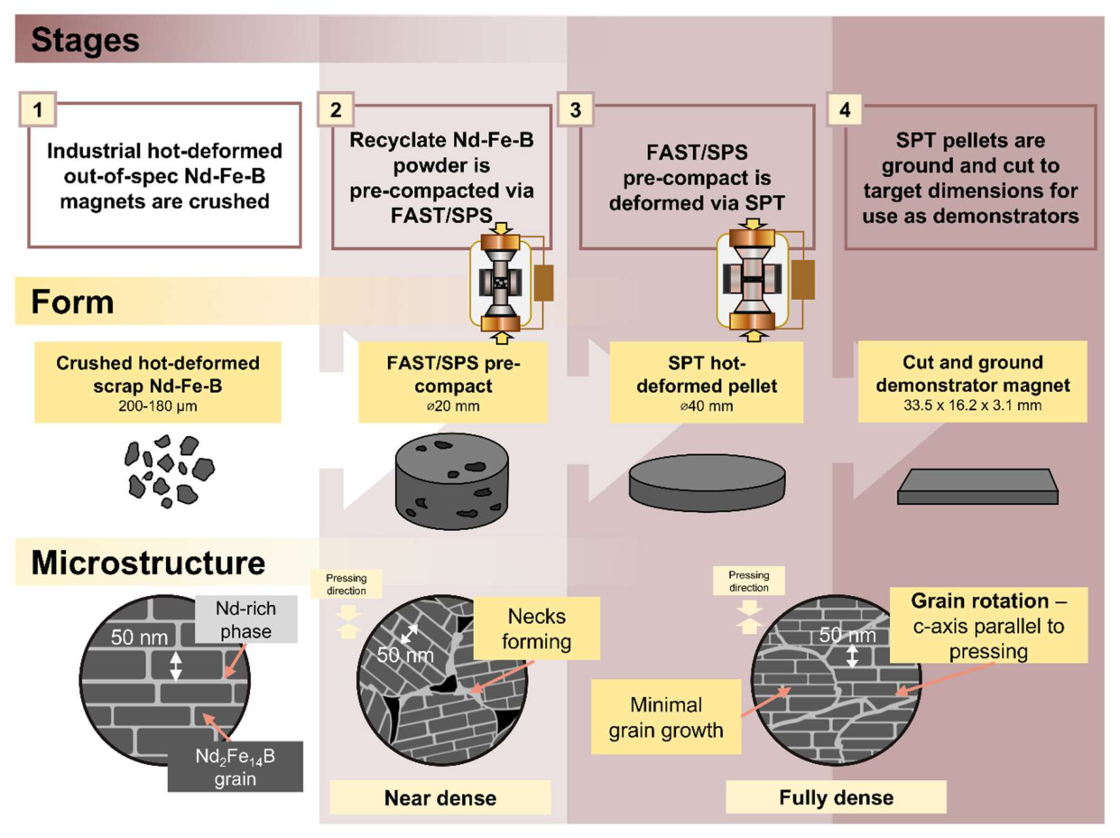
Figure 2.
Diagram of set-up of FAST/SPS for pre-compaction of Nd-Fe-B and SPT for deformation of the pre-compacted form.
Figure 2.
Diagram of set-up of FAST/SPS for pre-compaction of Nd-Fe-B and SPT for deformation of the pre-compacted form.
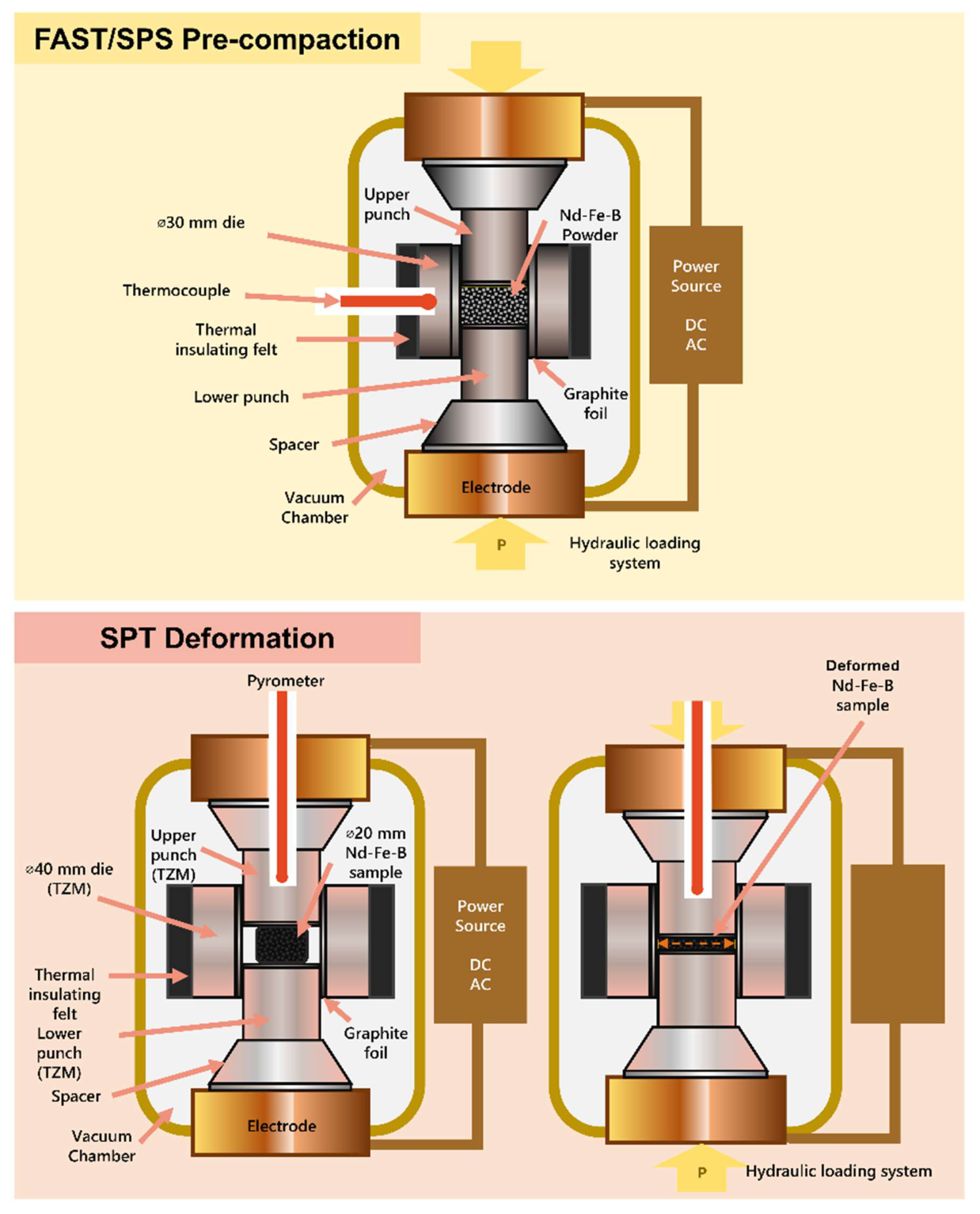
Figure 3.
BSE SEM images of pre-compacts A. LCM_C1, B. LCM_C2, and C. LCM_C3, listed with their average relative densities. Pressing direction of deformation is indicated with white arrows in the upper left corner of the images. Contrast has been adjusted for grain visibility.
Figure 3.
BSE SEM images of pre-compacts A. LCM_C1, B. LCM_C2, and C. LCM_C3, listed with their average relative densities. Pressing direction of deformation is indicated with white arrows in the upper left corner of the images. Contrast has been adjusted for grain visibility.
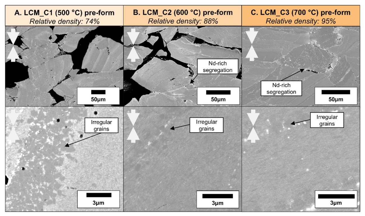
Figure 4.
Figure 4. A.) LCM_C4 pre-form, of roughly 15 mm in height, showing bowing from sample top to bottom, emphasized with orange arrows and B.) FAST/SPS set-up in the FCT HP-D25 device using a TZM die for C4 hot compaction.
Figure 4.
Figure 4. A.) LCM_C4 pre-form, of roughly 15 mm in height, showing bowing from sample top to bottom, emphasized with orange arrows and B.) FAST/SPS set-up in the FCT HP-D25 device using a TZM die for C4 hot compaction.
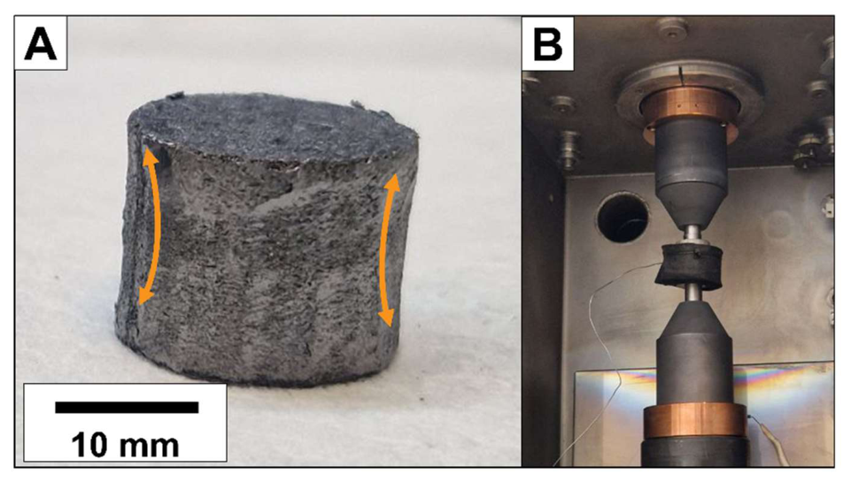
Figure 5.
BSE SEM images of LCM_C2_SPT showing regions of A.) well-aligned and B.) poorly-aligned grains. The direction of C-axes of the grains are indicated with light orange arrows, regions of oversized grains are outlined in orange boxes, and majorly misaligned grains are outlined in a yellow box. Pressing direction of deformation is indicated with white arrows in the upper left corner of the images.
Figure 5.
BSE SEM images of LCM_C2_SPT showing regions of A.) well-aligned and B.) poorly-aligned grains. The direction of C-axes of the grains are indicated with light orange arrows, regions of oversized grains are outlined in orange boxes, and majorly misaligned grains are outlined in a yellow box. Pressing direction of deformation is indicated with white arrows in the upper left corner of the images.
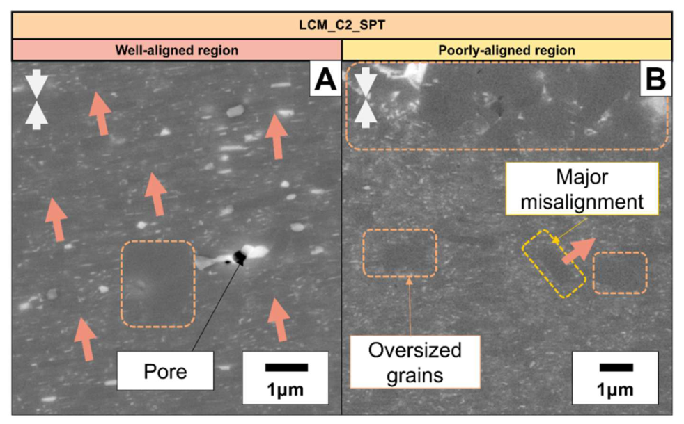
Figure 6.
A.) Diagram of section cut from LCM_C2_SPT for SEM analysis, and BSE SEM images of LCM_C2_SPT comparing B.) center with C.) edge. The directions of C-axes of the grains are indicated with light orange arrows. Pressing direction of deformation is indicated with white arrows in the upper left corner of the images.
Figure 6.
A.) Diagram of section cut from LCM_C2_SPT for SEM analysis, and BSE SEM images of LCM_C2_SPT comparing B.) center with C.) edge. The directions of C-axes of the grains are indicated with light orange arrows. Pressing direction of deformation is indicated with white arrows in the upper left corner of the images.
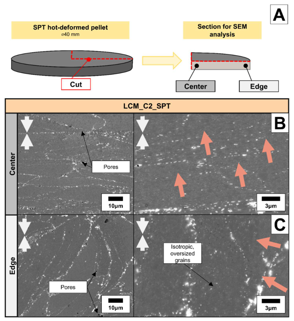
Figure 7.
Hysteresis curves for the A.) LCM and B.) L75_M25 samples after SPT deformation.
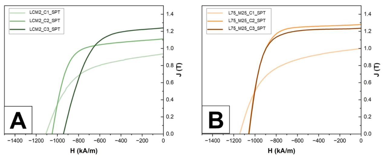
Figure 8.
LCM_C4_SPT samples A.) directly after extraction and B.) after smoothing of the faces.
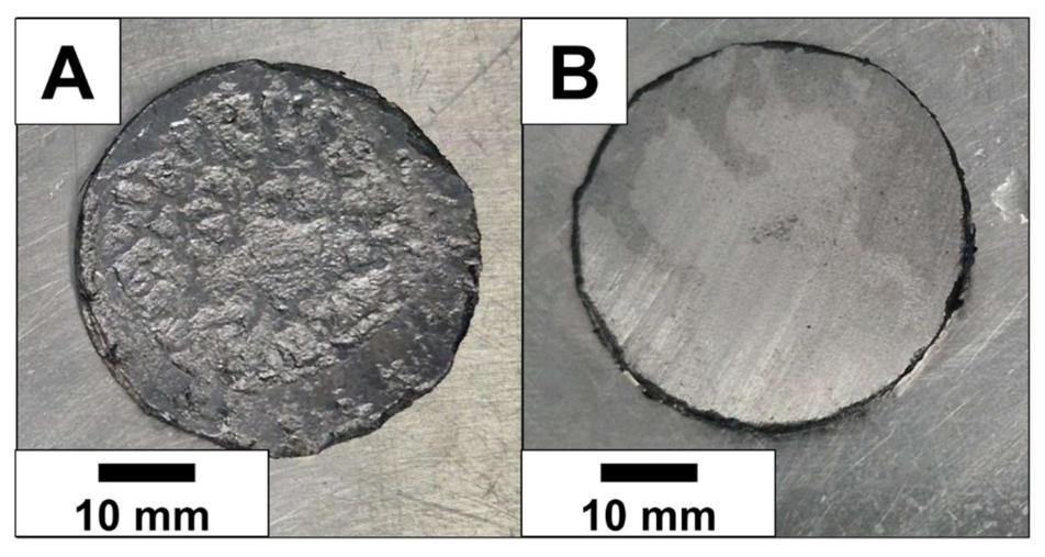
Figure 9.
Photos of A.) a bar magnet from LCM_C4_SPT after electrical discharge machining, showing damage in the corner from the deformation process, B.) a side-view of the bar magnet with a visible crack down the magnet bulk, C.) the rotor where the bar magnets were installed, along with the WILO SE circulating pump where the rotor was utilized, and D.) the set-up of the EMF measurement. Photos, electrical discharge machining, and EMF tests provided by WILO SE.
Figure 9.
Photos of A.) a bar magnet from LCM_C4_SPT after electrical discharge machining, showing damage in the corner from the deformation process, B.) a side-view of the bar magnet with a visible crack down the magnet bulk, C.) the rotor where the bar magnets were installed, along with the WILO SE circulating pump where the rotor was utilized, and D.) the set-up of the EMF measurement. Photos, electrical discharge machining, and EMF tests provided by WILO SE.
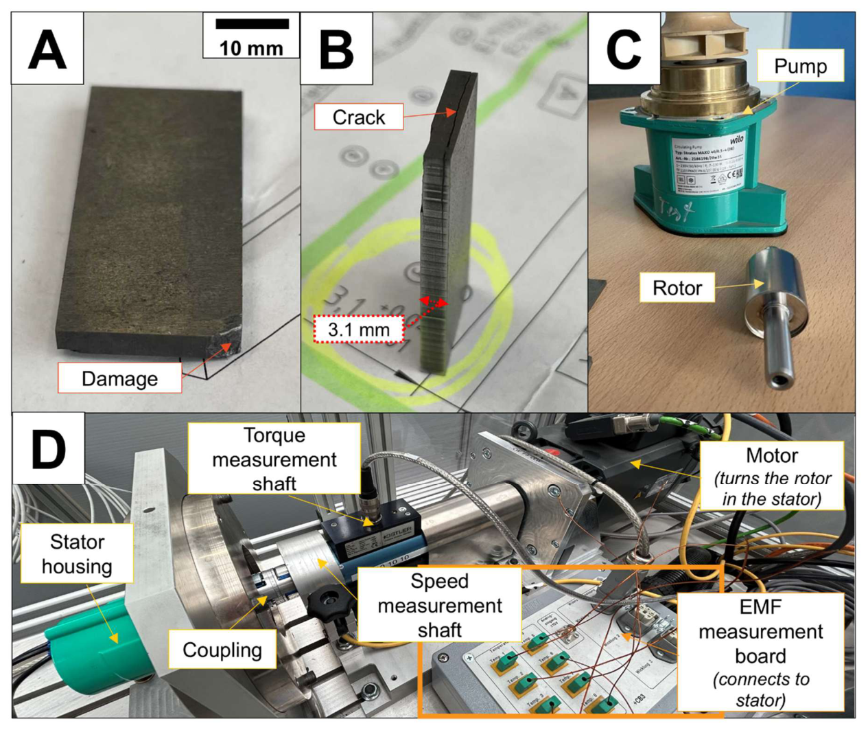

Table 1.
FAST/SPS parameters for different pre-compaction trials.
| Set Name | Powder mass (g) | Dwell Time (sec.) | Temperature (deg. C) |
Force (kN)/ Pressure (MPa) |
Diameter (mm) | Heating rate (K min-1) | Number of samples prepared |
| C1 | 30 | 120 | 500 | 16/50 | 20 | 100 | 1 |
| C2 | 30 | 60 | 600 | 16/50 | 20 | 100 | 1 |
| C3 | 30 | 60 | 700 | 16/50 | 20 | 100 | 1 |
| C4 | 35 | 60 | 600 | 16/50 | 20 | 100 | 6 |
Table 2.
Heights, diameters, and relative densities of pre-compacted samples. *C4 diameter variation was quite high due to bowing and had an influence on the calculation of the density.
Table 2.
Heights, diameters, and relative densities of pre-compacted samples. *C4 diameter variation was quite high due to bowing and had an influence on the calculation of the density.
| Sample | Height (mm) | Diameter (mm) | Relative density (%) |
| LCM_C1 | 16.4 | 20.5 | 74% |
| LCM_C2 | 13.5 | 20.6 | 88% |
| LCM_C3 | 12.9 | 20.6 | 95% |
| LCM_C4 | 15.0 | 20.7* | 92% |
| L75_M25_C1 | 16.2 | 20.5 | 73% |
| L75_M25_C2 | 13.8 | 20.5 | 87% |
| L75_M25_C3 | 12.9 | 20.6 | 93% |
Table 3.
Magnetic performance of all SPT deformed samples.
| Sample | HcJ (kA m-1) | Br (T) | (BH)max (kJ m-3) |
| LCM_C1_SPT | 1108 | 0.94 | 153 |
| LCM_C2_SPT | 1049 | 1.11 | 228 |
| LCM_C3_SPT | 943 | 1.24 | 277 |
| L75_M25_C1_SPT | 1144 | 1.00 | 175 |
| L75_M25_C2_SPT | 1060 | 1.28 | 313 |
| L75_M25_C3_SPT | 1057 | 1.24 | 295 |
Table 4.
Comparison of the EMF of a standard WILO rotor to rotor with DEMO magnets installed at the same rotational speed.
Table 4.
Comparison of the EMF of a standard WILO rotor to rotor with DEMO magnets installed at the same rotational speed.
| Magnets in rotor | Rotational Speed (rpm) | Electromotive force (V) |
| WILO standard | 4000 | 80.55 |
| LCM_C4_SPT | 4000 | 76.51 |
Disclaimer/Publisher’s Note: The statements, opinions and data contained in all publications are solely those of the individual author(s) and contributor(s) and not of MDPI and/or the editor(s). MDPI and/or the editor(s) disclaim responsibility for any injury to people or property resulting from any ideas, methods, instructions or products referred to in the content. |
© 2026 by the authors. Licensee MDPI, Basel, Switzerland. This article is an open access article distributed under the terms and conditions of the Creative Commons Attribution (CC BY) license (http://creativecommons.org/licenses/by/4.0/).
Copyright: This open access article is published under a Creative Commons CC BY 4.0 license, which permit the free download, distribution, and reuse, provided that the author and preprint are cited in any reuse.