Preprint
Article

This version is not peer-reviewed.

Continuous-Wave Terahertz Digital Holography Based on a Hollow Waveguide

Submitted:

14 May 2026

Posted:

15 May 2026

You are already at the latest version

Abstract
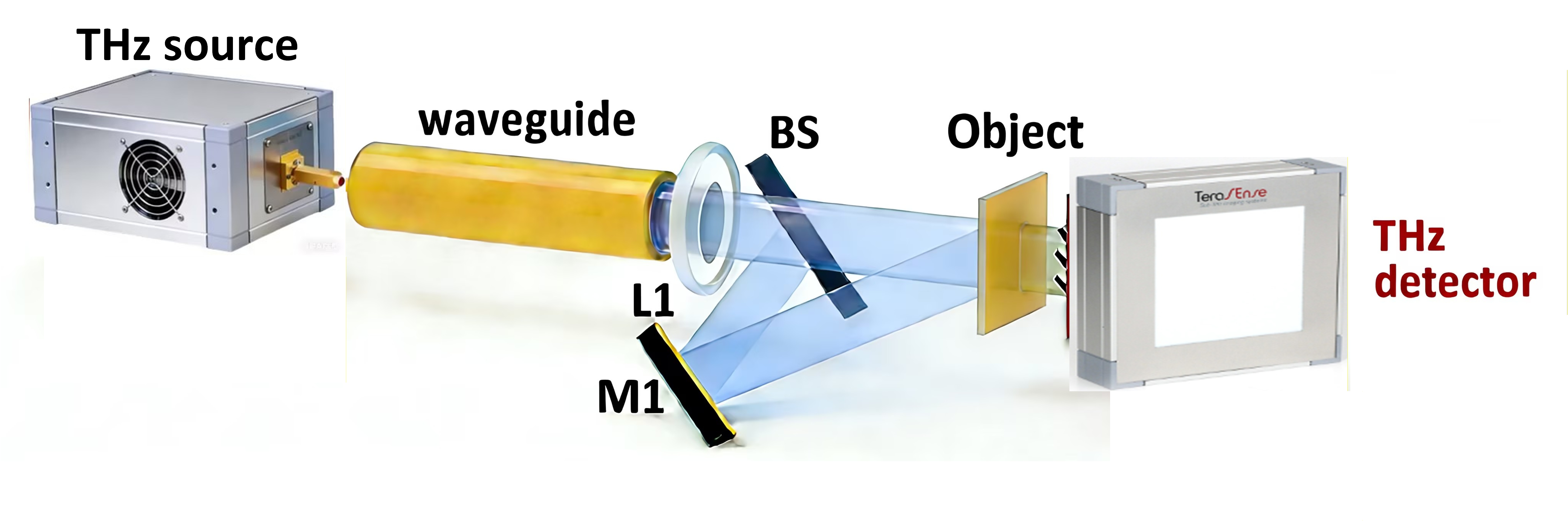
The major challenge limiting the application of terahertz(THz) technology lies in the significant attenuation of THz waves loss of THz waves during free-space transmission arising from water vapor absorption and gas molecule scattering. Compared with free space propagation, low-loss and stable transmission of THz wave can be achieved through the waveguide. Waveguide transmission at low THz frequencies has attracted considerable attention, particularly at around 300 GHz (0.3 THz). Among the various types of THz waveguides, hollow waveguides offer a simple structure, ease of fabrication, low cost, and excellent transmission performance in the THz regime. Here, we design and fabricate a low-loss THz metal dielectric hollow waveguide based on polypropylene (PP) tubing, where an external silver film coated on the PP tube forms a leaky-type hollow waveguide structure. The linear transmission loss is measured to be 1.35 dB/m at 300 GHz. By optimizing this low-loss THz hollow waveguide, we achieve a far-field THz digital holographic (TDH) imaging recording configuration for the first time. To evaluate the imaging performance, different types of samples are measured. Experimental results for a plastic plate with aluminum strips validate a lateral resolution of ∼2.5 mm. The proposed method holds potential as a powerful tool for investigating spontaneous phenomena in the THz band.
Keywords: 
;  ;  ;  

1. Introduction

With wavelengths ranging from 30 μm to 3 mm, possess unique properties including fingerprint spectral characteristics, excellent penetration through non-metallic and non-polar materials, and low photon energy, ensuring safety for both samples and operators. Consequently, THz imaging holds significant potential for characterizing various materials and imaging biological tissues. Over the past decade, both pulsed wave THz imaging and continuous wave THz imaging have been developed, enriching the field of THz research. THz imaging technology holds significant potential in characterizing various materials and biological tissues due to its strong penetrability, safety, and spectral fingerprint characteristics [1]. At low THz frequencies and below, where robust room-temperature electronic sources and sensitive detectors have been developed, the centimeter-scale diffraction-limited resolution poses a severe limitation for imaging. At high THz frequencies, on the other hand, sub-100 µm resolution can be achieved, but the penetration depth for weakly absorbing materials is very small [2], restricting such imaging configurations to thin samples. In this regime, coherent sources either suffer from low output power requiring pulsed operation, or rely on bulky cryogenic cooling equipment, such as quantum cascade lasers. There thus appears to be a spot between the high millimeter-wave and low THz frequencies, around 300 GHz, where the trade-off between resolution and penetration is suited to many applications [3], and where room-temperature sources with output powers in the hundreds of mW are becoming commercially available [4].
With the rapid development of THz unit devices such as high-performance THz sources and large-format, high-sensitivity area array detectors, THz digital holography (TDH) has emerged as a widely studied quantitative phase-contrast imaging technique in recent years. Transmission TDH, in particular, which can obtain the optical path difference and internal structural information of an object through phase information and and plays a crucial role in measuring the refractive index of objects [5,6,7]. Currently, THz waves experience significant loss during free-space transmission due to factors such as water vapor absorption and gas molecule scattering, which limits their application in imaging.
THz waveguides not only effectively confine THz waves within the waveguide structure, enabling functions such as waveform modulation, mode selection, and filtering, but also hold promise for achieving long-distance, stable, and low-attenuation transmission of THz waves. Among various THz waveguide structures, the hollow-core waveguide is notably simple, consisting of a central air core and a surrounding dielectric layer, with air serving as the transmission medium. Compared to free-space propagation, transmission within a waveguide can significantly reduce absorption caused by water vapor, theoretically enabling extremely low transmission losses. THz hollow-core waveguides can be primarily categorized into dielectric tube hollow-core waveguides, metal/dielectric hollow-core waveguides, metal (plated) hollow-core waveguides, and metamaterial-clad hollow-core waveguides. For metal/dielectric hollow waveguides and metal coated hollow waveguides, their performance in THz wave transmission is mainly influenced by the material of the polymer tube and the bonding effect with the metal coating. Common materials used for THz waveguides include quartz and polymer materials [8,9]. Compared to quartz, polymer materials exhibit lower absorption coefficients in the THz band, along with high transparency and flat dispersion characteristics. Consequently, polymer-based THz waveguides have progressively emerged as a significant research focus. Furthermore, the advanced state of the polymer processing industry renders the fabrication of dielectric tube hollow-core waveguides relatively straightforward, offering controllable quality and low cost, thereby presenting significant potential for large-scale production. In recent years, researchers have successfully utilized both commercially available and custom-designed polymer tubes as dielectric tube hollow-core waveguides to achieve efficient THz wave transmission [10,11,12,13,14]. Among the plethora of THz waveguide structures, metal-coated hollow-core THz waveguides possess distinct advantages, including a simple structure, absence of end-face reflections, low transmission loss, and a high damage threshold [15,16]. The structure of a metal-coated hollow-core waveguide primarily consists of an inner metallic coating and an outer supporting tube. Plastic tubes, prized for their excellent flexibility and smooth inner surface, are widely employed as the structural tube for hollow-core waveguides [17,18]. Owing to their simple structure, favorable bending performance, and low transmission loss, metal-coated THz hollow-core waveguides based on plastic tubes are regarded as highly promising candidates for THz waveguiding applications.
THz imaging research based on THz waveguide structures primarily utilizes the low-loss transmission characteristics of the waveguides. Furthermore, the waveguide can constrain the beam divergence angle at its output end to achieve subwavelength focusing. As a result, it can replace THz lenses and off-axis parabolic mirrors to perform two-dimensional scanning of objects and obtain subwavelength-resolution imaging [19,20]. However, research on THz phase-contrast imaging based on waveguides remains largely unexplored.
In this paper, we designed and built a TDH imaging system based on a THz hollow-core waveguide. The designed and fabricated THz dielectric hollow-core waveguide can not only reduce the transmission loss of THz waves, but also enable long-distance THz wave transmission and the construction of a reconfigurable imaging system at the end of waveguide. Finally, we performed measurements on samples including a THz resolution test target and opaque polyethylene plastic sheets based on this THD imaging system, obtaining full-field phase-contrast images with a resolution of approximately 2.5 mm. This technology holds significant application prospects in fields such as construction quality inspection and mineral resource exploration.

2. Principle of THz Hollow-Core Waveguide

Polypropylene (PP) is a common non-polar polymer material. In the THz band, it typically exhibits low absorption and low dispersion, making it as a highly suitable material for THz optical windows or substrates. A cylindrical PP sample with an inner diameter of 10 mm, a thickness of 0.36 mm, and a length of 50 mm was fabricated. Subsequently, the material was characterized in the THz band using a terahertz time-domain spectroscopy (THz-TDS) system. The THz-TDS pulse transmitted through the bulk material was measured, and the corresponding frequency-domain data were obtained by performing a fast Fourier transform on the THz-TDS waveform. Finally, the refractive index and absorption coefficient of the PP material in the THz range were calculated. The measured optical constants of the polymer material are presented in Figure 1. Within the frequency range of 0.2–3.0 THz, the refractive index of the PP material ranges from 1.49 to 1.55, and the absorption coefficient is less than 0.43 cm⁻¹. The low absorption of PP in the THz region indicates its potential for fabricating waveguides suitable for low-frequency THz wave transmission, and the results are in good agreement with previously reported values [21].
The transmission mechanism of hollow-core waveguides can be explained by the anti-resonant waveguide model, the dielectric layer in the high-refractive-index cladding region is regarded as a Fabry-Perot resonant cavity. The core is a region of low refractive index. Electromagnetic waves leak from the core region into the higher-refractive-index dielectric layer, where they oscillate, resulting in significant transmission loss. Therefore, the transmission region must correspond to the anti-resonant frequency range. By designing the cladding and the dielectric layer, we can control whether electromagnetic waves resonate within the Fabry-Perot cavity. If the thickness of the cladding satisfies the anti-resonant condition, light is reflected back into the low-refractive-index core region, thereby enabling low-loss transmission of electromagnetic waves within the core [21]. Here, we analyzed the relationship between the cladding wall thickness and the high-loss frequency. The c is the speed of light, t and n are the thickness and refractive index of the PP dielectric layer, respectively, and m represents a constant. Resonant frequency of the waveguide structure can be expressed as:
f m = m c 2 t n 2 1 ,
Based on the calculation, with a refractive index of 1.5 and a wall thickness designed is 0.36 mm, the corresponding anti-resonant high-loss frequency is 0.29 THz. Consequently, low-loss transmission can be achieved at the frequency of 0.3 THz.
Silver was chosen as the metallic reflective layer for the THz waveguide due to its high reflectivity throughout the entire THz frequency band. To enhance the transmission performance of the beam within the waveguide, the silver layer was deposited on the outer surface of the PP tube to fabricate an Ag/PP dielectric hollow-core waveguide. The transmission losses of the silver/PP hollow waveguides with different dielectric thicknesses were simulated by the ray model [22,23,24]. After silver plating, the transmission performance of the waveguide for THz waves is significantly improved. In previous studies, researchers have predominantly employed a liquid-phase dynamic deposition process [25,26]. In this paper, we use vacuum evaporation method to deposit the silver layer on the outer surface of the PP tube. The dielectric material is dissolved in a volatile solvent, and the resulting solution is injected into the tube. The liquid level is controlled to descend at a uniform speed, forming a liquid film. The solvent is then evaporated by means such as air blowing or heating, ultimately forming a uniform dielectric film layer. The transmission loss of the waveguide can be calculated as[27,28]:
α = 10 log P i n / P o u t L ,
where Pin is the output power of the coupler, that is, the input power of the waveguide to be tested, Pout is the output power of the waveguide to be measured, and L is the length of the waveguide to be measured.
The parameters of the designed waveguide were obtained through simulation, a schematic diagram of the preparation of Ag/PP THz hollow waveguide is shown in Figure2(a). The simulation results are presented in Figure 2(b) and (c). A horn waveguide antenna with a diameter of 20 mm was installed on this THz source, resulting in an output beam divergence angle of approximately 3°, which can be approximately considered as collimated beam. The maximum diameter of the THz illumination beam was about 16 mm. The output beam is shown in Figure 2(b), and the amplitude distribution of the beam during propagation within the waveguide is shown in Figure 2(c). It can be seen that the proposed waveguide works at a lower frequency, and the transmission loss is lower, which is suitable for THz wave to transmit over longer distances.
In this system, the thickness of the silver layer is approximately 420 nm, which is significantly greater than the skin depth (116 nm) for transmitting 300 GHz band. This indicates that the silver layer fabricated on the PP tube meets the requirements for the metal layer thickness in the waveguide structure design [18]. Consequently, a sample of the Ag/PP THz hollow waveguide with a length of 50 mm and an inner diameter of 20 mm was fabricated. Figure 3 presents the measured transmission performance of the fabricated waveguide. In the experiment, transmission loss of the waveguide was 1.35 dB/m and tested by 300 GHz source.

3. Experimental Results

The TDH experimental setup based on a waveguide imaging structure is shown in Figure 4. The THz source is a 300 GHz IMPATT diode THz source (Terasense), generating continuous THz wave with a wavelength of 1.07 mm and a average output power of 26 mW. The emitted THz beam exhibits a Gaussian profile with linear polarization, however, the beam quality is poor at the edges, and the intensity uniformity decreases with distance from the source. Due to the THz wave was strongly absorbed by water vapor in the air, so the THz wave is unsuitable for long-distance imaging applications. Upon emission from the THz source, the beam is coupled into the hollow THz waveguide, The coupler is made of the same material as the waveguide. After the beam passes through the TPX lens (L1: diameter: 25.4mm, focal length: 25mm), the output beam is collimated to THz plane wave. Subsequently, the THz wave passes through a high-resistivity silicon beam splitter(BS), where one beam illuminates the sample to be as the object beam, while the other as a reference beam is reflected by a THz mirror (M1) and recorded by the detector. The off-axis angle is about 43°. The object and reference beams interfere at the recording plane to generate a off-axis Fresnel hologram. The hologram is recorded by a THz camera (TeraSense Tera), which features a detection area of 64 × 64 pixels with a pixel pitch of 1.5 mm, resulting in an overall sensor size of 96 mm × 96 mm. The distance between the sample and the detector was ∼50 mm.
To quantify the resolution of the TDH based on the waveguide imaging system, a resolution test target was fabricated by pasting aluminum bar patterns on a polyethylene substrate (n=1.63 @300 GHz). Figure 5(a1) presents a photograph of the sample captured under white light, where the the illuminated region of the sample inside the white dash-line box, which serves as the sample for assessing the resolution of the imaging system. Figure 5(a2) presents the outline drawing of two groups of metal aluminum target strip, each group comprising three strips with a periods of 2.5 mm, the length of each aluminum strip is 12.5mm. The thickness of the polyethylene substrate plate was measured to be ∼1.98 mm by using a screw-thread micrometer.
In the experiment, the aluminum bar pattern side of the test target faced the detector, while the sample was tilted at an appropriate angle relative to the incident beam to minimize unwanted interference caused by multiple reflections from the substrate. The results in Figure 5(a1)-(d1) and (a2)-(d2) correspond to the TDH imaging systems without and with the waveguide, respectively. The results indicate that without the waveguide, the system can distinguish the width of the aluminum strips, but the imaging quality is poor and the signal-to-noise ratio is low. Figure 5(c) and (e) display the reconstructed amplitude image and phase image of the sample, respectively.
Figure 5(c1) and (c2) reveal that without the waveguide, the imaging system can resolve the width and spacing of the target bars in the resolution pattern. When the waveguide is added, the target bars can be more clearly distinguished from the background, the crosstalk between the target bars is suppressed to some extent, and the brightness of the target bars is higher. Combined with the central intensity profile line in Figure 5(d2) , the average difference between the measured width of the 2.5 mm aluminum target bars and the actual target bar width is 10%, and the imaging results exhibit a higher signal-to-noise ratio. The reason for this experimental results may be attributed to energy loss during the propagation of the THz beam in the actual experiment, which results in poorer imaging quality. This experiment results can show that the resolution of TDH based on the waveguide imaging system can reach 2.5 mm. The mean phase of the pasted areas was∼18.32 rad, corresponding to a thickness of ∼1.79 μm with a relative error of 10.6%.
Figure 6(a) shows a polystyrene (PS) plate patterned with letters, which was adopted as the sample. This refractive index and absorption coefficient are ~1.60 and 0.5cm−1 at 300 GHz, respectively. The thickness of the sample is ~390 μm. A photo of the actual pattern is shown in Figure 6(a), where the white dashed line indicates the imaging area. The distance from the sample to the detector is ~66.8 mm. Figure 6(b) shows the recorded hologram, and Figure 6(c) shows the reconstructed amplitude image of the sample. However, the letters can be clearly recognized in the Figure 6(c). In order to calculate the thickness of the sample, two holograms in the presence and absence the pattern and letters were recorded and reconstructed, separately. Besides phase unwrapping and aberration correction as mentioned above, the reconstructed background phase image was subtracted from the unwrapped phase containing sample’s information. The final phase image is represented in Figure 6(d). We calculated the phase unwrapping by using the least squares method during the experiment. A region with a slowly varying phase distribution was selected for calculating the sample thickness, the selected region is marked by the red rectangular box in the figure6(d). Based on the relationship between refractive index and thickness, h = Δ φ λ / ( 2 π ) , where λ and Δφ are the wavelength and phase difference, respectively. The mean phase in this region is ~2.27 rad, corresponding to an average thickness of ~361 μm, with a relative error of 7.43%.

5. Conclusions

Waveguide transmission at low THz frequencies has attracted widespread attention, particularly at the frequency of 300 GHz, we have constructed a hollow silver/PP waveguide for low-loss transmission of 300 GHz. the fabricated waveguide exhibits a relatively low straight attenuation of 1.35 dB/m at around 300 GHz. We proposed and demonstrated a TDH system based on this low-loss hollow waveguide, representing the first implementation of a full-field phase imaging approach at the 300 GHz band employing a waveguide. The advantages of this proposed layout is low loss, which enables excellent imaging quality. Transmissive imaging of a plastic plate with aluminum strips was achieved, yielding a resolution of 2.5 mm. Comparative experiments conducted under identical conditions with and without the waveguide reveal that the reconstruction quality is improved when the waveguide is employed. Phase-contrast imaging of a PS plate was also carried out. The experimental results demonstrate the validity of the proposed method and the effectiveness of the constructed system. This method is therefore considered to offer a new perspective for TDH imaging, with the advantage of reducing the propagation loss of THz waves in free space. It is expected to possess considerable technological potential for future THz imaging applications.

Author Contributions

Y.Z.: Methodology, Software, Writing—original draft. B.Z.: Writing—review & editing, Funding acquisition. L.C.: Supervision, Funding acquisition. J.D.: Formal analysis. All authors have read and agreed to the published version of the manuscript.

Funding

This research was supported by the Fundamental Research Program of Shanxi Province(202203021222336); the National Natural Science Foundation of China (5217555); the Higher Education Teaching Reform and Innovation Project of Shanxi Province(J20231863); the Scientific Research Foundation for Advanced Talents of Shanxi Institute of Science and Technology(2023009).

Data Availability Statement

Data underlying the results presented in this paper are not publicly available at this time but may be obtained from the authors upon reasonable request.

Conflicts of Interest

The authors declare no conflicts of interest.

References

  1. Zhang, Y.; Wang, C.; Huai, B.; Wang, S.; Zhang, Y.; Wang, D.; Rong, L.; Zheng, Y. Continuous-Wave THz Imaging for Biomedical Samples. Appl. Sci. 2021, 11, 71. [Google Scholar] [CrossRef]
  2. Tonouchi, M. Cutting-edge terahertz technology. Nat. Photonics 2007, 1, 97–105. [Google Scholar] [CrossRef]
  3. Appleby, R.; Wallace, H. B. Standoff detection of weapons and contraband in the 100 GHz to 1 thz region. IEEE Trans. Antennas Propag. 2007, 55, 2944–2956. [Google Scholar] [CrossRef]
  4. Deng, Q.; Li, W.; Wang, X. High-resolution terahertz inline digital holography based on quantum cascade laser. Opt. Eng. 2017, 56, 113102. [Google Scholar] [CrossRef]
  5. Zhang, Y.; Zhao, J.; Wang, D.; Wang, Y.; Rong, L. Lensless fourier-transform terahertz digital holography for real-time full-field phase imaging. Photonics Res. 2022, 10(2), 323. [Google Scholar] [CrossRef]
  6. Wang, D.; Zhang, Y.; Rong, L.; Ma, D.; Wang, Y. Continuous-wave terahertz self-referencing digital holography based on Fresnel’s mirrors. Opt. Lett. 2020, 45(4), 913–916. [Google Scholar] [CrossRef]
  7. Penketh, H.; Ergoktas, M.S.; Lawrence, C.R.; Phillips, D.B.; Cunningham, J.E.; Hendry, E.; Mrnka, M. Real-time millimeter wave holography with an arrayed detector. Opt. Express 2024, 32, 5783–5792. [Google Scholar] [CrossRef]
  8. Shaghik, A.; Shahraam, A. V.; Tanya, M.Monro. Terahertz dielectric waveguides. Adv. Opt. Photon. 2013, 5, 169–215. [Google Scholar]
  9. Khan, M.T.A.; Li, H.; Duong, N.N.M.; Blanco-Redondo, A.; Atakaramians, S. Terahertz Waveguide:3D-Printed Terahertz Topological Waveguides. Adv. Mater. Technol. 2021, 6, 2170040. [Google Scholar] [CrossRef]
  10. Stefani, A.; Henry; Skelton, J.; Tuniz, A. Bend losses in flexible polyurethane antiresonant terahertz waveguides. Opt. Express, 2021, 29, 28692–28703. [Google Scholar] [CrossRef]
  11. Wallis, R.; Innocenti, R.D.; Jessop, D.S.; Mitrofanov, O.; Bledt, C.M.; Melzer, J.E.; Harrington, J.A.; Beere, H.E.; Ritchie, D.A. Investigation of hollow cylindrical metal terahertz waveguides suitable for cryogenic environments. Opt. Express 2017, 24, 30002–30014. [Google Scholar] [CrossRef] [PubMed]
  12. Zhong, Y.; Xie, G.; Mao, F.; She, C.; Lu, X.; Yue, F.; Liu, S.; Jing, C.; Cheng, Y.; Chu, J. Thin-wall cyclic olefin copolymer tube waveguide for broadband terahertz transmission. Opt. Mater. 2019, 98, 109490. [Google Scholar] [CrossRef]
  13. Zhang, X.; Tan, Z.; Chen, K.; Li, W.; Zhao, Z.; Yu, S.; Zhu, X.; Cao, J.; S. Y. Transmission characteristics of dielectric-coated metallic waveguides in G band and 4.3 THz. J. Infrared Millim. Waves. 2019, 38, 215–222. [Google Scholar]
  14. Li, S.; Dai, Z.; Wang, Z.; Qi, P.; Su, Q.; Gao, X.; Gong, C.; Liu, W. 0.1 THz low-loss 3D printed hollow waveguide. Optik 2019, 176, 611–616. [Google Scholar] [CrossRef]
  15. He, M.; Chen, Z.; Zeng, J.; Chen, K.; Liu, S.; Zhang, X.; Zhu, X.; Jing, C.; Chang, C.; Shi, Y. Design, fabrication, and characterization of a single-polarization single-mode flexible hollow waveguide for low loss millimeter wave propagation. Opt. Express 2022, 30, 10178–10186. [Google Scholar] [CrossRef] [PubMed]
  16. Bledt, C. M.; Melzer, J.E.; Harrington, J.A. Fabrication and characterization of improved Ag/PS hollow-glass waveguides for THz transmission. Appl. Opt. 2013, 52, 6703–6709. [Google Scholar] [CrossRef]
  17. Bowden, B.; Harrington, J.A.; Mitrofanov, O. Silver/polystyrene-coated hollow glass waveguides for the transmission of terahertz radiation. Opt. Lett. 2007, 32, 2945–2947. [Google Scholar] [CrossRef]
  18. Xie, G.; Zhong, Y.; Li, G.; She, C.; Lu, X.; Yue, F.; Liu, S.; Jing, C.; Cheng, Y.; Chu, J. 300 GHz bending transmission of silver/polypropylene hollow terahertz waveguide. Results Phys. 2020, 19, 103534. [Google Scholar] [CrossRef]
  19. Wang, Z.; Li, X.; Wang, Q.; Gong, C.; Liu, W. Terahertz super-resolution imaging based on a confocal waveguide and a slider-crank scanning mechanism. Opt. Express 2023, 31, 19945–19957. [Google Scholar] [CrossRef]
  20. Li, X.; Wang, Z.; Jiang, H.; Deng, M.; Yin, L.; Gong, C.; Liu, W. Super-resolution terahertz imaging based on a meta-waveguide. Opt. Lett. 2024, 49, 1261–1264. [Google Scholar] [CrossRef]
  21. Duguay, Michel; Kokubun, Yasuo; Koch, T.; Pfeiffer, Loren. Antiresonant reflecting optical waveguides in SiO2-Si multilayer structures. Appl. Phys. Lett. 1986, 49, 13–15. [Google Scholar] [CrossRef]
  22. Miyagi, M. Waveguide-loss evaluation in circular hollow waveguides and its rayoptical treatment. J. Light. Technol. 1985, 3, 303–307. [Google Scholar] [CrossRef]
  23. Matsuura, Y.; Hongo, A.; Saito, M.; Miyagi, M. Loss characteristics of circular hollow waveguides for incoherent infrared light. J. Opt. Soc. Am. A. 1989, 6, 423–427. [Google Scholar] [CrossRef]
  24. Bledt, C.M.; Melzer, J.E.; Harrington, J.A. Theoretical and experimental investigation of infrared properties of tapered silver/silver halide-coated hollow waveguides. Appl. Opt. 2013, 52, 3703–3712. [Google Scholar] [CrossRef]
  25. Yan, M.; Mortensen, N.A. Hollow-core infrared fiber incorporating metal-wire metamaterial. Opt. Express 2009, 17, 14851–14864. [Google Scholar] [CrossRef] [PubMed]
  26. Wang, Z.; Li, X.; Wang, Q.; Gong, C.; Liu, W. Terahertz super-resolution imaging based on a confocal waveguide and a slider-crank scanning mechanism. Opt. Express 2023, 31, 19945–19957. [Google Scholar] [CrossRef]
  27. Setti, V.; Vincetti, L.; Argyros, A. Flexible tube lattice fibers for terahertz applications. Opt. Express 2013, 21, 3388–3399. [Google Scholar] [CrossRef] [PubMed]
  28. Yu, T.; Zuo, X.; Liu, W. W.; Gong, C. 0.1THz super-resolution imaging based on 3D printed confocal waveguides. Opt. Commun. 2020, 459, 124896. [Google Scholar] [CrossRef]
Figure 1. Refractive index and absorption coefficient of the PP medium as a function of frequency.
Preprints 213576 g001
Figure 2. Simulation results. (a) Amplitude distribution diagram of the outgoing beam spot; (b) Amplitude of the light beam during its transmission within the waveguide, and (c) .
Preprints 213576 g002
Figure 3. Measured and calculated the transmission loss of the Ag/PP THz hollow waveguide.
Preprints 213576 g003
Figure 4. Schematic of the configuration of the TDH based on the waveguide imaging system.
Preprints 213576 g004
Figure 5. Reconstruction results of a plastic plate with aluminum strip. (a1) The photograph of plastic plate with aluminum strip. (a2) Outline drawing of two groups of metal aluminum target strip. (b1)–(e1) are the hologram, the reconstructed amplitude and phase images respectively. (b2)-(e2) are the hologram, the reconstructed amplitude and phase images respectively by using TDH based on the waveguide imaging system.
Preprints 213576 g005
Figure 6. Reconstruction results of a polystyrene sample. (a) Photo and schematic pattern, (b) hologram, (c) reconstructed amplitude image, (d)reconstructed unwrapped phase image after background subtraction.
Preprints 213576 g006
Disclaimer/Publisher’s Note: The statements, opinions and data contained in all publications are solely those of the individual author(s) and contributor(s) and not of MDPI and/or the editor(s). MDPI and/or the editor(s) disclaim responsibility for any injury to people or property resulting from any ideas, methods, instructions or products referred to in the content.
Copyright: This open access article is published under a Creative Commons CC BY 4.0 license, which permit the free download, distribution, and reuse, provided that the author and preprint are cited in any reuse.
Prerpints.org logo

Preprints.org is a free preprint server supported by MDPI in Basel, Switzerland.

Subscribe

Disclaimer

Terms of Use

Privacy Policy

Privacy Settings

© 2026 MDPI (Basel, Switzerland) unless otherwise stated