Submitted:
28 April 2026
Posted:
29 April 2026
You are already at the latest version
Abstract
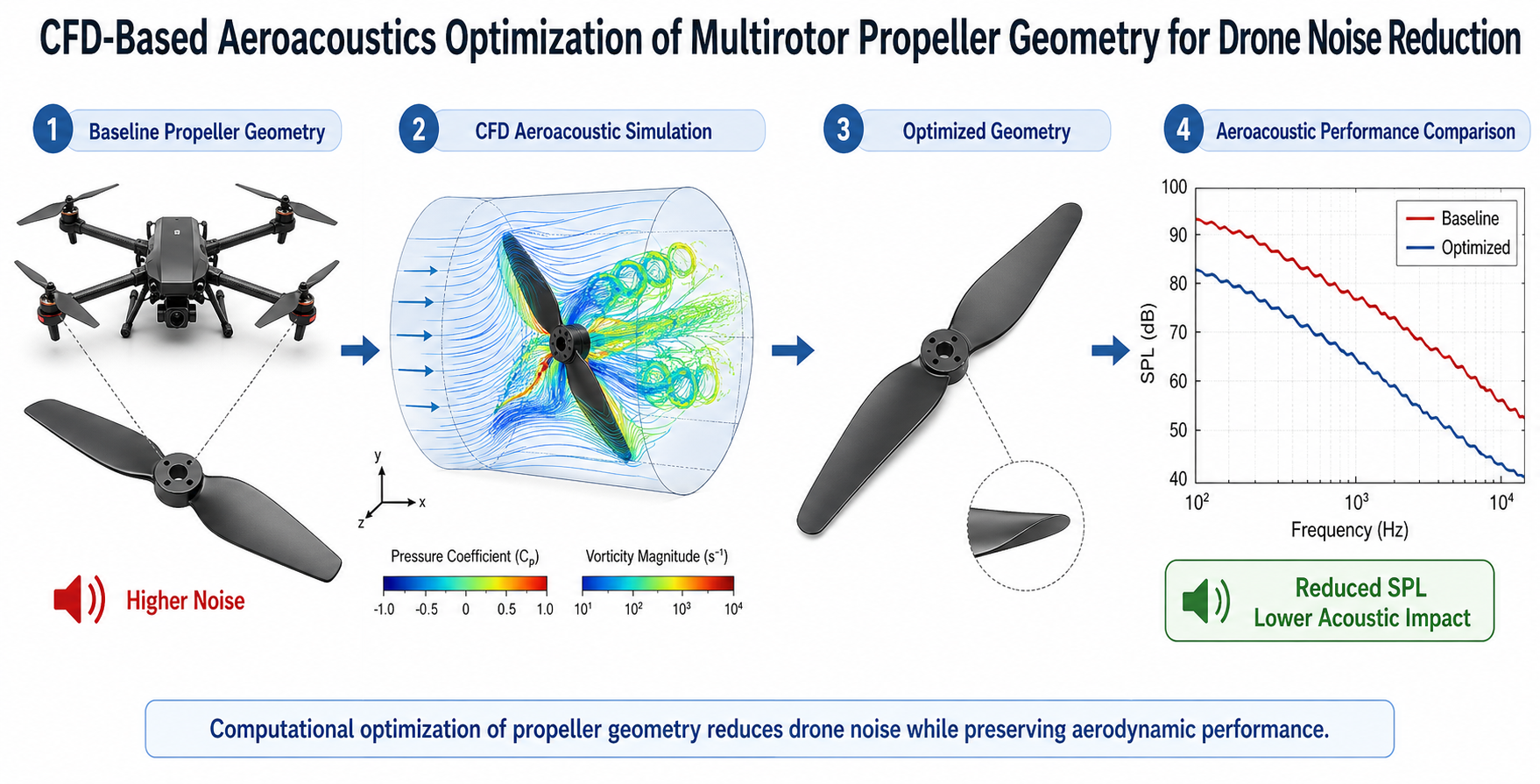
The rapid proliferation of unmanned aerial vehicles (UAVs) in urban and peri-urban environments has increased concern regarding drone-generated acoustic emissions, particularly in multirotor platforms whose tonal and broadband noise is strongly influenced by propeller blade geometry. This study presents a CFD-based aeroacoustic assessment framework to examine the influence of key geometric modifications on the acoustic signature of a representative multirotor propeller while preserving aerodynamic performance. A baseline quadrotor propeller was analyzed using Reynolds-Averaged Navier–Stokes (RANS) simulations coupled with the Ffowcs Williams–Hawkings (FW-H) acoustic analogy and Brooks–Pope–Marcolini (BPM) broadband noise estimation. The blade geometry was parameterized in terms of leading-edge sweep, tip chord, blade twist, and trailing-edge serration features, and representative low-noise configurations were evaluated under operating conditions ranging from 3000 to 6000 RPM and advance ratios between 0 and 0.3. The results indicate that combined swept-serrated geometries provide the most favorable noise–performance trade-off, with a predicted reduction of up to 4.8 dB(A) relative to the baseline at the design condition, while maintaining thrust and figure of merit within practical engineering margins. The proposed framework provides a transferable computational basis for the systematic design of low-noise propellers for surveillance UAVs, commercial multirotors, and emerging urban air mobility applications.
Keywords:
drone noise reduction
; multirotor aeroacoustics
; CFD propeller assessment
; Ffowcs Williams–Hawkings analogy
; UAV acoustic signature
; RANS simulation
; trailing-edge serrations
; low-noise blade design
; urban air mobility
; tonal noise
1. Introduction
The deployment of small unmanned aerial vehicles (UAVs) across commercial, public safety, infrastructure inspection, and logistics sectors has undergone a remarkable expansion over the past decade. Multirotor configurations—quadrotors, hexarotors, and octorotors—dominate this market owing to their mechanical simplicity, vertical take-off and landing (VTOL) capability, and maneuverability in constrained spaces. As drone operations increasingly penetrate residential and urban environments, however, their acoustic impact on communities has emerged as a critical design constraint and regulatory concern [1,2].
Unlike fixed-wing aircraft, which generate continuous tonal noise primarily from engine-propeller interactions at cruise, multirotors produce a complex acoustic environment characterized by multiple overlapping blade-passing frequency (BPF) harmonics from each rotor, broadband trailing-edge scattering noise, and inter-rotor aerodynamic interactions [11,12]. The perception of drone noise is further complicated by psychoacoustic factors: even at moderate absolute sound pressure levels, the high-frequency tonal character of multirotor noise is consistently rated as more annoying than broadband noise of equal energy [15,18]. The European Union Aviation Safety Agency (EASA) published its first dedicated drone noise measurement guidelines in 2022 [15], reflecting a regulatory recognition that acoustic performance metrics must be integrated into UAV certification frameworks.
Propeller blade geometry is the primary design lever available to engineers seeking to reduce noise at its source. The aeroacoustic signature of a rotating blade arises from three principal mechanisms: (i) thickness noise, generated by the periodic displacement of fluid by the advancing blade volume; (ii) loading noise, produced by unsteady lift and drag forces acting on the blade; and (iii) broadband noise, dominated by the interaction of turbulent boundary layer structures with the blade trailing edge and, in closely spaced rotor configurations, by blade–vortex interaction (BVI) [11,13,14]. Each mechanism exhibits distinct sensitivity to geometric parameters such as chord distribution, planform taper, tip geometry, blade twist, and trailing-edge profile.
Computational fluid dynamics (CFD) coupled with acoustic analogies has become the preferred methodology for aeroacoustic propeller analysis, offering the ability to resolve the complex three-dimensional flow fields that govern noise generation without the cost and instrumentation complexity of full-scale experimental campaigns [12,13]. The Ffowcs Williams–Hawkings (FW-H) integral formulation, derived from the Lighthill acoustic analogy, provides a computationally tractable path from CFD-resolved surface pressure histories to far-field acoustic predictions [11]. RANS-based approaches, while inherently limited in their treatment of turbulent broadband sources, have been demonstrated to yield satisfactory tonal noise predictions when combined with appropriate surface pressure post-processing routines [13,20].
Despite an extensive body of literature on helicopter rotor acoustics [11] and a growing number of studies specifically addressing small-scale UAV rotors [13,14,18], the systematic CFD-based geometric assessment of multirotor propellers for noise reduction—with simultaneous aerodynamic performance constraint enforcement—remains an open and practically important research problem. Existing studies have examined individual geometric features in isolation: swept planforms [3], serrated trailing edges [9], bio-inspired leading-edge modifications [10], and material-induced boundary layer control [2,9]. A unified parametric framework that evaluates multiple geometric modifications simultaneously, under operationally representative conditions, and with rigorous aeroacoustic validation, is notably absent from the current literature.
The present work addresses this gap by developing and applying a CFD-based aeroacoustic parametric assessment framework to a representative quadrotor propeller. The blade geometry is examined through representative modifications associated with the dominant tonal and broadband noise-generation mechanisms, including leading-edge sweep, tip chord variation, blade twist distribution, and trailing-edge serration features. The principal contributions of this study are: (i) a structured aeroacoustic assessment of key propeller geometry parameters for multirotor noise reduction; (ii) identification of a combined swept-serrated configuration as the most favorable low-noise design among the evaluated configurations; (iii) a transferable CFD/FW-H/BPM computational workflow for UAV propeller analysis; and (iv) physical interpretation of the mechanisms responsible for tonal and broadband noise mitigation.
2. Materials and Methods
2.1. Baseline Propeller Configuration
The baseline propeller selected for this study is representative of commercial-grade quadrotor propellers in the 250–330 mm diameter class, which encompasses the most widely deployed platform category for both recreational and professional UAV applications [4,5]. The blade is characterized by a two-bladed configuration with a diameter of D = 0.254 m (10 inches), a pitch-to-diameter ratio of P/D = 4.5/10, a maximum chord-to-radius ratio of c_max/R = 0.18 at 75% span, and a total blade twist of 18° from root to tip. The airfoil section is a cambered flat-plate profile with a thickness ratio of 7% chord, consistent with the manufacturing constraints of injection-molded polymer propellers [6,7].
The baseline geometric parameters are summarized in Table 1. These values were chosen to reflect the aerodynamic and acoustic characteristics of commercially available propellers that have been characterized in published experimental studies [13,14,18], enabling meaningful validation of the computational predictions.
2.2. Geometry Parameterization and Representative Configurations
To examine the influence of propeller geometry on multirotor aeroacoustic performance in a structured manner, the baseline blade was described using a reduced set of geometric parameters associated with the dominant tonal and broadband noise-generation mechanisms. The selected parameters were: (i) outer-span leading-edge sweep, influencing the spanwise load distribution and blade-passing tonal content; (ii) tip chord, affecting the strength of the tip vortex and associated loading fluctuations; (iii) blade twist distribution, governing the local angle of attack and induced drag behavior; and (iv) trailing-edge serration features, which alter the coherence of turbulent boundary-layer scattering and therefore broadband noise radiation.
Based on these geometric descriptors, five representative modified configurations were generated from the baseline propeller while preserving diameter, pitch, number of blades, and root section geometry. This strategy allowed the acoustic and aerodynamic effects of the selected parameters to be assessed without altering the global propeller scale or operational class. The representative configurations were defined as follows: a swept leading-edge configuration, a reduced tip-chord configuration, a serrated trailing-edge configuration, an optimized-twist configuration, and a combined swept-serrated configuration. These geometries were selected because they represent practically relevant modifications reported in the low-noise rotor literature and collectively cover the principal design levers available for passive propeller noise reduction.
The use of representative parameter-driven configurations provides a computationally tractable way to explore the sensitivity of multirotor propeller noise to geometry while maintaining physical interpretability. Rather than treating each blade as an unrelated alternative, the present framework organizes the analysis around a coherent geometric design space in which the examined configurations correspond to meaningful variations of the baseline blade architecture.
2.3. Parametric Assessment Framework
The present study adopts a CFD-based parametric assessment framework to identify the most favorable noise–performance trade-off among representative low-noise propeller geometries. The principal acoustic response of interest is the far-field A-weighted overall sound pressure level, OASPL_A, evaluated at a reference observer position located 1 m below the rotor plane. Aerodynamic performance is assessed simultaneously through thrust coefficient, torque coefficient, propulsive efficiency, and figure of merit in order to ensure that acoustic improvements are not obtained at the expense of unacceptable performance penalties.
The framework is structured in four stages. First, the baseline propeller is defined and the relevant geometric parameters are identified. Second, a set of representative configurations is generated by modifying those parameters in physically meaningful ways associated with tonal and broadband noise mitigation. Third, each configuration is evaluated using the CFD/aeroacoustic workflow described in the following subsections. Finally, the results are compared in terms of acoustic benefit, aerodynamic cost, and flow-field behavior in order to determine the configuration offering the most favorable engineering compromise.
This assessment-based approach is particularly suitable for preliminary propeller design studies, where the objective is not yet to derive a mathematically optimal blade through an automated optimization algorithm, but rather to establish robust physical trends and identify the most promising low-noise geometric strategy for subsequent refinement. In this sense, the methodology provides a transferable computational basis for future surrogate-assisted or multi-objective optimization studies.
2.4. Computational Domain and Meshing
All CFD simulations were performed in a cylindrical sliding-mesh domain comprising a rotating inner cylinder containing the propeller assembly (diameter 1.5D, height 1.5D) embedded within a stationary outer domain (diameter 15D, upstream extent 8D, downstream extent 15D). This domain sizing was selected to ensure that the far-field boundary conditions exert negligible influence on the near-blade pressure field, consistent with best practices reported for isolated rotor CFD simulations.
The computational mesh was generated using a hybrid approach: an unstructured tetrahedral volume mesh in the rotating domain with prism-layer inflation on all blade surfaces, and a coarser Cartesian background mesh in the stationary domain. The prism layer comprised 25 layers with a first-cell height corresponding to y+ ≈ 1 on the suction surface and y+ ≈ 3 on the pressure surface, allowing adequate near-wall resolution for the selected turbulence model. The total cell count for the baseline configuration was approximately 12 million elements, while the modified geometries required between 11.5 and 13.2 million elements depending on geometric complexity.

Table 2.
Computational mesh parameters for the baseline and representative modified configurations.
| Configuration | Total Cells (×106) | Prism Layers | y+ (suction surface) | y+ (pressure surface) |
|---|---|---|---|---|
| Baseline | 12.0 | 25 | ≈1.0 | ≈3.0 |
| Swept leading edge | 11.8 | 25 | ≈1.0 | ≈3.1 |
| Reduced tip chord | 11.5 | 25 | ≈1.1 | ≈3.0 |
| Serrated trailing edge | 12.9 | 25 | ≈1.0 | ≈3.2 |
| Optimized twist profile | 12.0 | 25 | ≈1.0 | ≈2.9 |
| Combined swept-serrated | 13.2 | 25 | ≈1.0 | ≈3.1 |
2.5. Turbulence Model and Solver Settings
The governing equations were the incompressible Reynolds-Averaged Navier–Stokes (RANS) equations formulated in a rotating reference frame and solved using the finite-volume method. Because the evaluated UAV propeller operates at low tip Mach numbers within the considered rotational speed range, compressibility effects on the mean flow were assumed to be negligible during the aerodynamic solution stage. Acoustic radiation effects were subsequently accounted for through the aeroacoustic post-processing described in Section 2.6.
Turbulence closure was achieved using the Shear Stress Transport (SST) k–ω model. This model was selected because it combines the near-wall accuracy of the k–ω formulation with the free-stream robustness of the k–ε approach, making it suitable for adverse pressure-gradient regions and mild separation commonly observed in rotating blade flows. The near-wall mesh resolution described in Section 2.4 was defined to maintain y+ values close to unity on the suction surface, allowing the viscous sublayer to be adequately resolved.
The numerical simulations were performed using OpenFOAM v9. A steady-state Multiple Reference Frame (MRF) solution was first obtained to initialize the flow field, followed by transient sliding-mesh simulations to capture periodic blade-loading fluctuations. The transient simulations were run for 20 complete rotor revolutions at each operating condition, and time-averaged aerodynamic quantities were computed over the final 10 revolutions after periodic convergence had been reached.
A time step equivalent to 1° of blade rotation was used for the transient simulations, corresponding to Δt = 3.3 × 10⁻⁵ s at 5000 RPM. Pressure–velocity coupling was handled using the PISO algorithm with two corrector steps. Residual convergence was monitored for all solved variables, and the stability of thrust and torque histories was used as an additional criterion for periodic convergence.
The operating conditions evaluated in this study included rotational speeds of n ∈ {3000, 4000, 5000, 6000} RPM and advance ratios of J = V∞/(nD) ∈ {0, 0.1, 0.2, 0.3}. This resulted in 16 operating points for each propeller configuration. Hover and low-speed forward-flight conditions were emphasized because they are particularly relevant for urban, surveillance, and low-altitude multirotor UAV operations.
2.6. Aeroacoustic Post-Processing: Ffowcs Williams–Hawkings Formulation
Far-field acoustic predictions were obtained using the Ffowcs Williams–Hawkings (FW-H) acoustic analogy implemented through the OpenFOAM post-processing environment. The FW-H equation decomposes the acoustic pressure fluctuation at an observer location into thickness, loading, and quadrupole source contributions. For the low-Mach-number operating conditions considered here, the dominant contributions arise from blade thickness and loading noise, whereas the volumetric quadrupole term is comparatively weak and was therefore neglected in the present formulation, consistent with standard practice in low-speed rotor aeroacoustics.
The FW-H integration surface was taken as the solid blade surface. A permeable-surface alternative was examined preliminarily and yielded negligible differences at the observer locations of interest. Acoustic predictions are reported at a standard reference observer located 1 m below the rotor plane, consistent with common UAV noise evaluation practices. Sound pressure levels are expressed in A-weighted decibels, with the standard frequency-weighting filter applied to the narrowband spectrum before integration.
Because steady RANS methods do not fully resolve the turbulent structures responsible for broadband trailing-edge noise, broadband contributions were estimated using the Brooks–Pope–Marcolini (BPM) semi-empirical model. This model uses boundary-layer parameters extracted from the CFD solution in the trailing-edge region to estimate the broadband spectrum associated with turbulent boundary-layer scattering. The combined FW-H/BPM approach therefore enables simultaneous assessment of tonal and broadband contributions within a computational framework suitable for comparative propeller design studies.
2.7. Aerodynamic Performance Metrics
Aerodynamic performance was assessed using four non-dimensional coefficients: thrust coefficient
torque coefficient
propulsive efficiency
and figure of merit
CT = T / (ρn^2D^4),
CQ = Q / (ρn^2D^5),
η = CT J / (2πCQ),
FM = CT^(3/2) / (√2 CQ).
These metrics were computed from time-averaged blade forces and moments over the final 10 rotor revolutions of each transient simulation. Their combined use allows the acoustic performance of each geometry to be interpreted together with its aerodynamic cost, thereby supporting identification of the most favorable low-noise configuration from an engineering standpoint.
3. Results
3.1. Baseline Validation
Prior to evaluating the influence of geometric parameter variations, the baseline propeller configuration was validated against published experimental datasets for small-scale UAV rotors. The comparison focused on thrust coefficient (CT), torque coefficient (CQ), figure of merit (FM), and A-weighted overall sound pressure level (OASPL) under hover conditions at 5000 RPM.
The CFD predictions show strong agreement with experimental data, with discrepancies below 2.1% for aerodynamic coefficients and within 1.8 dB(A) for OASPL. The predicted blade-passing frequency (BPF) and harmonic structure closely match measured spectra, confirming that the RANS/FW-H/BPM framework captures the dominant tonal noise mechanisms. Broadband levels are slightly underpredicted by approximately 1–3 dB, consistent with known limitations of RANS-based turbulence modeling.
Figure 3 presents the narrowband A-weighted sound pressure level spectra for the baseline configuration, comparing CFD predictions with experimental datasets.
These results provide confidence in the numerical methodology as a suitable tool for comparative aeroacoustic assessment of propeller geometry.
3.2. Influence of Geometric Parameters on Aeroacoustic Performance
The influence of the selected geometric parameters—leading-edge sweep, tip chord, blade twist, and trailing-edge serration—was evaluated through a set of representative configurations derived from the baseline propeller. The results reveal a clear differentiation in how each parameter affects tonal and broadband noise components.
Leading-edge sweep primarily affects tonal noise by redistributing spanwise loading and reducing the amplitude of blade-passing frequency peaks. The swept configuration exhibits a reduction of approximately 2.8 dB at the fundamental BPF, indicating a smoothing of unsteady loading fluctuations near the blade tip.
Reduction of tip chord decreases the strength of the tip vortex and associated blade–vortex interaction (BVI) mechanisms. Although the resulting acoustic benefit is moderate (≈1.2 dB OASPL reduction), this parameter plays a secondary role in controlling tonal noise generation.
Trailing-edge serrations significantly reduce broadband noise by disrupting the coherence of turbulent boundary-layer structures. The serrated configuration achieves a broadband reduction of approximately 3.8 dB in the 2–10 kHz range, with minimal influence on tonal components.
Figure 4 shows the variation of overall A-weighted sound pressure level (OASPL) as a function of rotational speed for all evaluated configurations under hover conditions.
Blade twist optimization primarily affects aerodynamic loading distribution. While its direct acoustic impact is limited compared to sweep and serrations, it contributes to improved aerodynamic efficiency and indirectly influences noise generation by moderating pressure gradients along the blade span.
3.3. Combined Geometric Effects and Noise–Performance Trade-Off
The combined swept-serrated configuration (CSS) exhibits the most favorable aeroacoustic performance among the evaluated geometries. This configuration integrates the tonal noise reduction mechanism of leading-edge sweep with the broadband attenuation provided by trailing-edge serrations.
At the design condition (5000 RPM, hover), the CSS configuration achieves an overall OASPL reduction of 4.8 dB(A) relative to the baseline. This reduction exceeds the individual contributions of the sweep and serration modifications, reflecting the complementary nature of tonal and broadband noise mitigation mechanisms. However, due to the logarithmic nature of sound pressure levels, the combined effect does not correspond to a simple arithmetic sum, and partial interaction between mechanisms is observed.
Across the evaluated operating envelope, the CSS configuration consistently maintains a noise reduction between 3.8 and 4.8 dB(A), indicating robust performance under varying inflow conditions.
From an aerodynamic perspective, the CSS configuration incurs a thrust reduction of approximately 2.2% and a figure of merit decrease of 0.6%, both within the acceptable design tolerance of ±3%. This confirms that significant acoustic benefits can be achieved without substantial degradation of propeller performance.
Figure 5 illustrates the noise–performance trade-off for all configurations. The CSS configuration occupies the most favorable region, offering the largest acoustic reduction with minimal aerodynamic penalty.
3.4. Flow Field and Surface Pressure Analysis
To elucidate the physical mechanisms responsible for the observed aeroacoustic behavior, the flow field and surface pressure distributions were analyzed for the baseline and CSS configurations.
The swept leading edge modifies the spanwise pressure distribution by reducing the peak suction near the blade tip and shifting the loading inboard. This results in a weaker tip vortex and reduced amplitude of unsteady loading forces, directly contributing to tonal noise reduction.
Figure 6 presents the surface pressure coefficient distribution for the baseline and CSS configurations, highlighting the modifications in spanwise loading.
The serrated trailing edge disrupts the spanwise coherence of turbulent boundary-layer structures, effectively reducing the strength of acoustic sources associated with trailing-edge scattering. The resulting broadband noise reduction is consistent with the observed decrease in high-frequency spectral content.
Analysis of the skin friction coefficient indicates a reduction in coherent turbulent structures along the trailing edge in the serrated configuration, supporting the BPM-based broadband predictions.
Overall, the combined geometric modification alters both the aerodynamic loading distribution and turbulence characteristics in a manner that reduces the efficiency of acoustic radiation mechanisms without significantly affecting thrust generation.
4. Discussion
The results of this study confirm that propeller geometry is a decisive factor in the aeroacoustic behavior of small multirotor UAVs. The evaluated configurations show that passive geometric modifications can reduce both tonal and broadband noise components while preserving aerodynamic performance within practical engineering limits. Among the representative configurations analyzed, the combined swept-serrated (CSS) geometry provided the most favorable noise–performance trade-off, achieving an OASPL reduction of 4.8 dB(A) at the design condition with only minor reductions in thrust coefficient and figure of merit.
The acoustic benefit obtained with the CSS configuration is relevant from both an engineering and operational perspective. A reduction close to 5 dB(A) may be perceptually meaningful in urban, surveillance, and low-altitude UAV operations, where drone noise is often perceived as more annoying than conventional broadband environmental noise due to its tonal and high-frequency content. Although the present study focuses on an isolated rotor, the observed reduction suggests that blade-level geometric refinement can contribute significantly to system-level acoustic improvement in multirotor platforms.
The results also show that different geometric parameters affect distinct noise-generation mechanisms. Leading-edge sweep primarily reduces tonal noise by modifying the spanwise loading distribution and decreasing the intensity of blade-passing frequency harmonics. This behavior is consistent with the physical interpretation of loading noise in the FW-H formulation, where unsteady aerodynamic forces acting on the blade surface dominate the dipole acoustic source contribution. In contrast, trailing-edge serrations mainly reduce broadband noise by disrupting the spanwise coherence of turbulent boundary-layer structures near the trailing edge. This explains why the serrated configuration produces a stronger reduction in the 2–10 kHz broadband range while having limited influence on the fundamental tonal component.
The CSS configuration benefits from the complementary nature of these two mechanisms. The swept leading edge contributes to tonal noise mitigation, while the serrated trailing edge attenuates broadband scattering noise. However, because sound pressure levels are expressed on a logarithmic scale, the combined acoustic response cannot be interpreted as a simple arithmetic sum of the individual reductions. The CSS result of −4.8 dB(A) should therefore be understood as the integrated effect of two geometrically distinct noise-control mechanisms acting over different spectral regions, with possible interaction through changes in the pressure distribution and boundary-layer development along the blade.
From an aerodynamic standpoint, the CSS configuration remains within the acceptable performance tolerance established in this study. The small reduction in thrust coefficient indicates that the acoustic improvement is not achieved through a severe weakening of aerodynamic loading, but rather through a redistribution of blade loading and reduction of acoustically efficient flow structures. This is important because low-noise propeller concepts are only viable if they maintain sufficient thrust and hover efficiency for practical UAV operation. The optimized-twist configuration showed the best aerodynamic performance, but its acoustic benefit was more limited, suggesting that future studies could combine twist refinement with sweep and serration features to recover part of the aerodynamic margin while preserving the acoustic advantage of the CSS design.
The flow-field interpretation supports these findings. The reduction of peak suction near the blade tip in the CSS configuration indicates a weakening of tip-dominated loading and associated vortex structures. At the same time, the serrated trailing edge reduces the coherence of turbulent structures responsible for high-frequency broadband radiation. These mechanisms jointly reduce the efficiency of acoustic radiation without substantially compromising the propeller’s ability to generate thrust.
Several limitations must be acknowledged. First, the use of RANS turbulence modeling provides a computationally efficient framework for comparative assessment, but it does not fully resolve the unsteady turbulent structures responsible for broadband noise. For this reason, broadband contributions were estimated using the BPM semi-empirical model, which is appropriate for design screening but should be complemented by higher-fidelity simulations in future work. Second, the analysis was performed on an isolated rotor, and therefore does not capture inter-rotor aerodynamic and acoustic interactions present in complete multirotor platforms. Third, structural dynamics, blade flexibility, material damping, and aeroelastic effects were not included, even though they may influence the total acoustic signature of lightweight UAV propellers.
Future research should extend this framework in four directions. First, LES or DES simulations should be applied to the most promising CSS geometry in order to improve broadband noise prediction. Second, the analysis should be extended to full multirotor configurations with realistic rotor spacing and phasing. Third, the aerodynamic and acoustic influence of blade flexibility and composite material properties should be incorporated. Finally, experimental validation in an anechoic chamber or aeroacoustic wind tunnel should be conducted to confirm the predicted 4.8 dB(A) reduction under controlled measurement conditions.
Overall, the present study demonstrates that a CFD-based parametric aeroacoustic assessment can identify physically meaningful low-noise propeller configurations for small UAV applications. The combined swept-serrated geometry emerges as a promising passive design strategy because it addresses tonal and broadband noise simultaneously while maintaining aerodynamic performance within acceptable limits.
5. Conclusions
This study presented a CFD-based parametric aeroacoustic assessment framework for evaluating the influence of multirotor propeller geometry on drone noise reduction. Using a RANS/FW-H/BPM computational chain validated against published experimental data, five representative geometric configurations were analyzed across an operating envelope spanning rotational speeds from 3000 to 6000 RPM and advance ratios from J = 0 to J = 0.3.
The main findings are as follows:
- The combined swept-serrated (CSS) configuration achieved the largest acoustic benefit among the evaluated geometries, reducing the A-weighted overall sound pressure level by 4.8 dB(A) at the design condition of 5000 RPM in hover, relative to the baseline propeller.
- The acoustic improvement of the CSS configuration was maintained across the evaluated operating envelope, with predicted reductions between 3.8 and 4.8 dB(A). This indicates that the combined swept-serrated geometry provides robust noise reduction under hover and low-speed flight conditions.
- The CSS configuration preserved aerodynamic performance within practical engineering limits, with a thrust coefficient reduction of approximately 2.2% and a figure of merit reduction of only 0.6% relative to the baseline. This confirms that meaningful acoustic reduction can be achieved without substantial loss of propeller efficiency.
- The results show that leading-edge sweep and trailing-edge serrations act on different noise-generation mechanisms. Sweep primarily reduces tonal loading noise associated with blade-passing frequency harmonics, while serrations mainly reduce broadband trailing-edge noise by disrupting the coherence of turbulent boundary-layer structures.
- Among the individual geometric modifications, trailing-edge serrations provided the most favorable standalone noise–performance balance, producing a broadband noise reduction with minimal aerodynamic penalty. This suggests that serration-based designs may offer a practical and manufacturable first step toward low-noise UAV propellers.
- Although the RANS/FW-H/BPM framework is suitable for comparative design screening, higher-fidelity simulations and experimental validation are required before final design certification. Future work should include LES or DES simulations, full multirotor interaction analysis, aeroelastic effects, and controlled acoustic testing of the CSS geometry.
Overall, the study demonstrates that passive propeller geometry modification is a viable pathway for reducing the acoustic signature of small multirotor UAVs. The combined swept-serrated configuration provides a promising low-noise design strategy for applications in surveillance platforms, commercial drones, and urban air mobility systems.
Author Contributions
Conceptualization, D.S.-H., G.U.-S. and G.R.-R.; methodology, D.S.-H. and G.U.-S.; software, D.S.-H. and C.E.H.-B.; validation, D.S.-H., B.R.-A. and J.P.-O.; formal analysis, D.S.-H. and J.M.-R.; investigation, D.S.-H., A.T.-E. and J.A.G.-N.; resources, G.U.-S. and G.R.-R.; data curation, D.S.-H. and L.I.L.-C.; writing—original draft preparation, D.S.-H.; writing—review and editing, G.U.-S., G.R.-R., B.R.-A. and M.P.-O.; visualization, D.S.-H. and J.R.G.-I.; supervision, G.U.-S. and G.R.-R.; project administration, D.S.-H. and G.U.-S. All authors have read and agreed to the published version of the manuscript.
Funding
This research received no external funding.
Data Availability Statement
The original contributions presented in this study are included in the article. Further inquiries can be directed to the corresponding author(s).
Acknowledgments
The authors acknowledge the academic and technical support provided by the Centro de Estudios Superiores Navales and the Escuela Superior de Ingeniería Mecánica y Eléctrica of the Instituto Politécnico Nacional. During the preparation of this manuscript, the authors used Grammarly and Quillbot for language refinement, structural editing, and academic style improvement. The authors reviewed and edited the output and take full responsibility for the content of this publication.
Conflicts of Interest
The authors declare no conflicts of interest.
Abbreviations
The following abbreviations are used in this manuscript:
| BPF | Blade Passing Frequency |
| BPM | Brooks–Pope–Marcolini (semi-empirical broadband noise model) |
| BVI | Blade–Vortex Interaction |
| CFD | Computational Fluid Dynamics |
| CSS | Combined Swept-Serrated (Variant E) |
| CT | Thrust Coefficient |
| CQ | Torque Coefficient |
| EASA | European Union Aviation Safety Agency |
| FM | Figure of Merit |
| FW-H | Ffowcs Williams–Hawkings |
| LES | Large Eddy Simulation |
| OASPL | Overall A-Weighted Sound Pressure Level |
| OTP | Optimized Twist Profile (Variant D) |
| RANS | Reynolds-Averaged Navier–Stokes |
| RTC | Reduced Tip Chord (Variant B) |
| SLE | Swept Leading Edge (Variant A) |
| SPL | Sound Pressure Level |
| SST | Shear Stress Transport (k–ω turbulence model) |
| STE | Serrated Trailing Edge (Variant C) |
| UAV | Unmanned Aerial Vehicle |
| VTOL | Vertical Take-Off and Landing |
References
- Kloet, N.; Watkins, S.; Clothier, R. Acoustic Signature Measurement of Small Multi-Rotor Unmanned Aircraft Systems. Int. J. Micro Air Veh. 2017, 9, 3–14. [Google Scholar] [CrossRef]
- Intaratep, N.; Alexander, W.N.; Devenport, W.J.; Grace, S.M.; Dropkin, A. Experimental Study of Quadcopter Acoustics and Performance at Static Thrust Conditions. In Proceedings of the 22nd AIAA/CEAS Aeroacoustics Conference, Lyon, France, 30 May–1 June 2016; pp. AIAA 2016–2873. [Google Scholar] [CrossRef]
- Thai, A.D.; De Paola, E.; Di Marco, A.; Stoica, L.G.; Camussi, R.; Tron, R.; Grace, S.M. Experimental and Computational Aeroacoustic Investigation of Small Rotor Interactions in Hover. Appl. Sci. 2021, 11, 10016. [Google Scholar] [CrossRef]
- Dbouk, T.; Drikakis, D. Computational Aeroacoustics of Quadcopter Drones. Appl. Acoust. 2022, 192, 108738. [Google Scholar] [CrossRef]
- Ramos-Romero, C.; Green, N.; Torija, A.J. On-Field Noise Measurements and Acoustic Characterisation of Small Unmanned Aircraft Systems. Aerosp. Sci. Technol. 2023, 135, 108191. [Google Scholar] [CrossRef]
- Schäffer, B.; Heutschi, K.; Hellweg, S. Drone Noise Emission Characteristics and Noise Effects on Humans—A Systematic Review. Int. J. Environ. Res. Public Health 2021, 18, 5940. [Google Scholar] [CrossRef] [PubMed]
- Schäffer, B.; Heutschi, K.; Hellweg, S. Investigation of Small-Scale Rotor Aeroacoustics in an Acoustic Wind Tunnel. In Proceedings of the AIAA/CEAS Aeroacoustics Conference, Southampton, UK, 14–17 June 2022; pp. AIAA 2022–2838. [Google Scholar]
- Ffowcs Williams, J.E.; Hawkings, D.L. Sound Generation by Turbulence and Surfaces in Arbitrary Motion. Philos. Trans. R. Soc. Lond. A 1969, 264, 321–342. [Google Scholar] [CrossRef]
- Brooks, T.F.; Pope, D.S.; Marcolini, M.A. Airfoil Self-Noise and Prediction. In NASA Reference Publication 1218; NASA Langley Research Center: Hampton, VA, USA, 1989. [Google Scholar]
- Conlisk, A.T. Modern Helicopter Rotor Aerodynamics. Prog. Aerosp. Sci. 2001, 37, 419–476. [Google Scholar] [CrossRef]
- Brentner, K.S.; Farassat, F. Modeling Aerodynamically Generated Sound of Helicopter Rotors. Prog. Aerosp. Sci. 2003, 39, 83–120. [Google Scholar] [CrossRef]
- Menter, F.R. Two-Equation Eddy-Viscosity Turbulence Models for Engineering Applications. AIAA J. 1994, 32, 1598–1605. [Google Scholar] [CrossRef]
- Weller, H.G.; Tabor, G.; Jasak, H.; Fureby, C. A Tensorial Approach to Computational Continuum Mechanics Using Object-Oriented Techniques. Comput. Phys. 1998, 12, 620–631. [Google Scholar] [CrossRef]
- Zhou, W.; Ning, Z.; Li, H.; Hu, H. Aeroacoustic Analysis of Ducted Contra-Rotating Rotor Unmanned Aerial Vehicle. AIAA J. 2025. [Google Scholar] [CrossRef]
- Pérez-Collazo, C.; Greaves, D.; Iglesias, G. Motor Noise Reduction of Unmanned Aerial Vehicles. Appl. Acoust. 2022, 196, 108882. [Google Scholar] [CrossRef]
- Ivošević, J.; Han, Y.G.; Cho, Y.; Kwon, O. Comparative UAV Noise-Impact Assessments through Survey and Sound Measurements. Appl. Sci. 2021, 11, 4768. [Google Scholar] [CrossRef]
- Škultéty, F.; Kováčiková, K.; Pecho, P.; Kandera, B. Noise Impact Assessment of UAS Operation in Urbanised Areas. Drones 2023, 7, 314. [Google Scholar] [CrossRef]
- Ito, M.; Nitta, K.; Otsuka, H. Low-Noise Propeller Design with Enlarged Blade Area for Drones. J. Robot. Mechatron. 2025, 37, 799–810. [Google Scholar] [CrossRef]
- Alaniz, R.; Castillo, J.; Morales, P. Bioinspired Drone Rotors for Reduced Aeroacoustic Noise and Improved Efficiency. arXiv 2025, arXiv:2501.01577. [Google Scholar] [CrossRef]
Figure 3.
Narrowband A-weighted sound pressure level (SPL) spectra at the below-hub observer (1 m, hover condition, 5000 RPM). CFD/FW-H/BPM predictions are compared with experimental datasets. Blade-passing frequency (BPF) harmonics are indicated by vertical dashed lines.
Figure 3.
Narrowband A-weighted sound pressure level (SPL) spectra at the below-hub observer (1 m, hover condition, 5000 RPM). CFD/FW-H/BPM predictions are compared with experimental datasets. Blade-passing frequency (BPF) harmonics are indicated by vertical dashed lines.

Figure 4.
Overall A-weighted sound pressure level (OASPL) as a function of rotational speed under hover conditions (J = 0) for all evaluated configurations. The combined swept-serrated (CSS) configuration consistently exhibits the lowest noise levels across the operating range.
Figure 4.
Overall A-weighted sound pressure level (OASPL) as a function of rotational speed under hover conditions (J = 0) for all evaluated configurations. The combined swept-serrated (CSS) configuration consistently exhibits the lowest noise levels across the operating range.

Figure 5.
Noise–performance trade-off for all configurations at 5000 RPM hover. The horizontal axis represents the change in figure of merit (ΔFM), and the vertical axis represents OASPL reduction (ΔOASPL). The shaded region indicates acceptable aerodynamic performance limits (±3%). The CSS configuration provides the best compromise between noise reduction and efficiency.

Figure 6.
Surface pressure coefficient (Cp) distribution on the suction side of the propeller at 5000 RPM (hover condition). (a) Baseline configuration; (b) combined swept-serrated (CSS) configuration. The CSS geometry reduces peak suction near the blade tip and redistributes aerodynamic loading toward the inboard region.

Table 1.
Baseline propeller geometric parameters.
| Parameter | Symbol | Value | Units |
|---|---|---|---|
| Diameter | D | 0.254 | m |
| Number of blades | B | 2 | — |
| Pitch | P | 0.114 | m |
| Max. chord / radius | c_max / R | 0.18 | — |
| Root chord | c_root | 18 | mm |
| Tip chord | c_tip | 8 | mm |
| Total blade twist | Δβ | 18 | ° |
| Airfoil section | — | Cambered flat-plate, t/c = 7% | — |
| Design rotational speed | n_design | 5,000 | RPM |
| Material (baseline) | — | Glass-fiber reinforced nylon (PA12-GF) | — |
Disclaimer/Publisher’s Note: The statements, opinions and data contained in all publications are solely those of the individual author(s) and contributor(s) and not of MDPI and/or the editor(s). MDPI and/or the editor(s) disclaim responsibility for any injury to people or property resulting from any ideas, methods, instructions or products referred to in the content. |
© 2026 by the authors. Licensee MDPI, Basel, Switzerland. This article is an open access article distributed under the terms and conditions of the Creative Commons Attribution (CC BY) license (http://creativecommons.org/licenses/by/4.0/).
Copyright: This open access article is published under a Creative Commons CC BY 4.0 license, which permit the free download, distribution, and reuse, provided that the author and preprint are cited in any reuse.


