Submitted:
24 April 2026
Posted:
27 April 2026
You are already at the latest version
Abstract
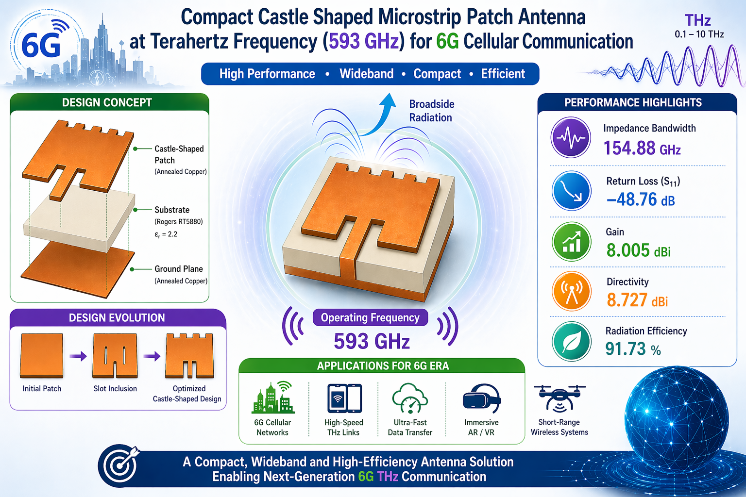
The fast growth of wireless communication systems and the growing need for very high data rates have been the driving force behind the creation of sixth-generation (6G) technologies that operate in the terahertz (THz) frequency region. This research represents the design and analysis of a small compact microstrip patch antenna that works in the terahertz (THz) frequency range for 6G cellular connectivity. The Rogers RT5880 substrate and annealed copper are used in the design of the suggested antenna, which aims for a 593 GHz resonance frequency. A progressive design technique that incorporates slotting and geometric optimization has been used to develop a castle shaped antenna which improve impedance matching and bandwidth to overcome the inherent constraints of traditional microstrip antennas. Excellent impedance matching is shown by the final design's near-ideal voltage standing wave ratio (VSWR) and return loss (S11) of –48.76 dB. It achieves a broad impedance bandwidth of 154.88 GHz, which far outperforms many current systems. The antenna exhibits consistent radiation characteristics in the broadside direction, a gain of 8.005 dBi, a directivity of 8.727 dBi, and an efficiency of around 91.73%. The proposed design performs very well in terms of bandwidth and efficiency, while also preserving compact dimensions and structural simplicity, as shown by a comparative comparison with most current literature. These results validate the suitability of the proposed antenna for high-speed, short-range THz communication systems in future 6G networks.
Keywords:
antenna design
; wireless communication
; sixth generation (6G)
; terahertz (THz)frequency band
; cellular communication
; microstrip patch antenna
; wide bandwidth
1. Introduction
In the last few decades, modern wireless communications have grown very quickly. To support the large volumes of data required by high-data-rate apps, demand for greater bandwidth has grown. Moreover, the need for high data rates for high-definition video transmission and reception, and enormous traffic is constantly increasing. To keep up with the contemporary world’s constantly increasing need for connection and data, the fifth generation of wireless communication (5G) delivers a major advance over the 4G network [1,2,3]. That’s why 5G was introduced in the last decade.
With higher speeds than 5G networks, however, 6G networks will be more reliable, have more bandwidth, and have substantially less latency. Due to their higher frequencies, 6G networks can send and receive data much more quickly than 5G networks. Compared to 5G, 6G will use energy and communication spectrum much more efficiently. It will also have a much higher access rate (10–100 times higher), faster access delay, and better communication reach across a wider area. Within a radius of 10 meters, the terahertz frequency may be utilized for superfast data transfer. The cellular networks’ tiny cells provide coverage in this region. Terahertz communication may be used inside and out by stationery and moving users. Terabit wireless local area networks (T-WLAN) allow error-free data transfer between ultra-fast fiber optic connections and mobile devices like laptops and tablets. In the terahertz range, both wired and wireless connections are equally fast. As a result, antennas and RF (radio frequency) systems may continually improve in terms of their materials, processes, technologies, and forms of implementation [4,5]. The 6G wireless communication network system relies heavily on the THz frequency spectrum. The frequency range known as the terahertz band extends from 0.1 to 10 terahertz. The frequency range from 0.1 to 0.3 THz is classified as the sub-THz zone, and the frequency range from 0.3 to 10 THz is classified as the THz region [6]. THz band wireless communication has also been proposed for use in a variety of niche areas, including healthcare monitoring systems, ultra-high-speed on-chip communication, IoNT (internet of nano things), pollution monitoring in the environment, defense and military applications, entertainment sector, and heterogeneous networks [7]. Other names may refer to the THz band, including T waves and Tera waves [8].
While smart technologies are developing rapidly, the field of antennas has also been growing quickly every year. This is because antennas are very important in the wireless field. Recently, a lot of researchers have become interested in patch antennas because they are small, flexible, and cheap, among others. Because of these advantages, this kind of antenna has found more uses and is now a part of many current fields and new sixth-generation (6G) wireless systems [9,10]. But because they are small, they work great for high frequencies, like terahertz frequencies, which have very short ranges. Patch antennas can work well at these frequencies, which makes them useful for many uses that need a wide frequency and fast data transfer. Even though terahertz patch antennas have some benefits, they still have some problems because they don’t work very well and don’t use energy very efficiently. Researchers have suggested several ways to discover answers to these issues. Some of these ideas include the use of a partial ground plane rather than a whole ground plane [11], the utilization of slots on the patch or the substrate [12], and the addition of superstrate [13].
Researchers are putting a lot of effort into creating effective antenna systems that work in the terahertz (THz) band because of the growing need for wireless communication that can handle large data demands quickly. Despite the fact that microstrip patch antennas have a number of benefits, such being small and easy to integrate, there are still obstacles to their performance at THz frequencies related to efficiency, bandwidth, and radiation characteristics.
To address these restrictions and fulfill the needs of 6G communication systems, it is crucial to develop and improve patch antennas. Improved antenna performance in the THz range is possible via structural changes such slot inclusion and the use of modern design methodologies. Therefore, this research proposes a unique castle shaped microstrip patch antenna that operates in the THz band and has a center frequency of 593 GHz. Due to its low profile, affordability, flexibility in selecting the feed line, and directional properties, this type of antenna is a common design option in telecommunication networks. The patch has several slots, which are exploited to create the required radiation pattern, level of efficiency, and frequency range.
This article includes multiple parts that depict the antenna design process using CST software. First, section 2 discusses the literature study of several antenna designs for 6G and Terahertz networks from recent publications. A short overview of the material, design, and parameter specification is provided in Section 3. Simulation results and related antenna properties are assessed in Section 4 to determine the effectiveness of the designed antenna. Next, a comparison study and proposed model’s limits, applicability, is presented in Section 5. Finally, Section 6 presents a conclusion and a summary of the study.
2. Literature Review
In the 19th century, Deschamps and Robert E. Munson introduced microstrip patch antennas [14]. After that, numerous researchers continued developing and enhancing the microstrip patch antenna day by day as well. In the last three decades, an enormous development was noticed in the microstrip antenna fields by analyzing lightweight highlighted and printed circuit boards (PCB) [15]. Earlier in 2026, Younes et al. [16] proposed a metamaterial-based T-shaped antenna which is mainly array based antenna for 6G networks which achieved a gain of 6.21 dBi, and a directivity of 7.23 dBi with S₁₁ of -58.376 dB, a VSWR of 1.002. But it has moderate bandwidth of 120GHz. A flexible polyimide-based terahertz antenna has been proposed by Elabd et al. [17] on the year 2025 for 6G application. That MIMO array-based antenna achieves a maximum gain of around 10dB, S11 of -39dB efficiency over 90% but bandwidth of 19 GHz which is very low. In 2023, Ghzaoui et al. proposed Metamaterial-based substrate integrated waveguide (SIW) technique antenna for 6G Sub-Terahertz applications where bandwidth, gain and return loss achieved 108.5 GHz, 11.3 dBi and <-50 respectively [18].
In January 2023, Uri Nissanov et al. [19] proposed a GCPW based microstrip array antenna for wireless 6G networks where the bandwidths, gain, and directivity are 26.1 GHz, 12.1 dBi, and 12.98 dBi, respectively. In the same year, Chemweno et al. [20] designed a wideband SIW-fed dielectric resonator (DR) antenna with a bandwidth of 28 GHz. That antenna exhibits steady broader radiation patterns, with gain of 11.67 dBi, directivity of 13.36 dBi, and an overall efficiency of 79%. The same researcher developed another communication antenna in September 2022. It is a rectangular SIW-fed DR antenna that works in the D-band. In this band, resonances are combined to achieve a -10 dB impedance spread between 122.58 GHz and 139.51 GHz, with a center frequency of 125.76 GHz. In this case, the DR element is excited via a narrow slot; this design produces a multi-resonant antenna that can operate at six different frequencies. Additionally, the antenna has a stable radiation pattern in the broadband direction over the entire operating frequency range. The antenna has a maximum gain of 12.3 dBi, a directivity of 13.14 dBi, and an efficiency of 84% at 126 GHz [21]. In 2021, a 6G communication antenna in sub terahertz spectrum was proposed by Hamsakutty et al., which has a gain of 10 dBi and a directivity of 17 dBi [22]. Same year, at 300 GHz, a ring slotted waveguide-based array antenna suggested by Ansha et al. [23] attained a gain of 15.3 dBi and an impedance bandwidth of 88 GHz between 244 GHz and 332 GHz.
In December 2020, S. N. Hafizah Sa’don et al. [24] proposed a low-gain antenna for 6G applications operating at 300 GHz with a bandwidth of 53.15 GHz. Then, an air gap gain enhancement technique was applied, which made it possible to obtain a higher simulation bandwidth of 86.66 GHz and a higher simulation gain of 5.41 dBi.
By reviewing earlier research, it can be found that the use of metamaterials and array in the antenna designing is increasing so, designs are growing more sophisticated and smaller to improve bandwidth and overall efficiency. A single patch (microstrip) antenna provides several advantages over an array antenna, mainly due to its simple design, low cost, and ease of fabrication, as it does not require complex feeding networks. It is compact, lightweight, and consumes less power, making it suitable for portable and embedded applications, while also offering easier impedance matching and eliminating mutual coupling effects. In addition, its design and analysis are less complex and faster compared to array antennas. Similarly, normal materials like FR-4 or Rogers substrates are chosen over metamaterials in antenna manufacturing because to their affordability, accessibility, and ease of production using traditional PCB procedures. They are better suited for large-scale manufacturing and provide consistent, reliable performance. Although metamaterials can improve certain properties like gain and bandwidth, their higher cost and fabrication complexity make conventional materials a more practical choice for most real-world antenna applications. Moreover, earlier research study state that a compromise must be made between gain, directivity, and return loss. So, this research combines seemingly contradictory factors, emphasizing bandwidth while presenting a more basic approach using conventional Rogers RT 5880 (Lossy) material.
3. Materials, Design, and Parameter Specifications
Within the framework of the creative design approach process, the structural synthesis of Composite Compact Planar Grating Transitions (CCPGTs) will be carried out [7,8]. There are three steps to the process:
3.1. Materials Selection
To construct the antenna, a substrate layer composed of Rogers RT5880 has been coupled with two layers of annealed copper (Cu) material. Due to having a characteristic of better electrical conductivity at a reduced cost, Annealed Copper has been chosen to construct the Ground and Patch layer of the proposed antenna. Moreover, following an evaluation of factors, including the reflection coefficient or S-Parameters, Voltage Standing Wave Ratio (VSWR), and other critical considerations, the selection of copper (Cu) material has been made to enhance performance [25]. To enhance the design realism, Annealed Copper and ‘Lossy’ type Rogers RT5880 component has been opted during simulation, mentioned that the used substrate (Rogers RT5880) has a dielectric permittivity of 2.2 and a loss tangent value of approximately 0.004. After a meticulous material selection, the antenna design underwent simulation using CST STUDIO SUITE software.
3.2. Antenna Architecture
The architectural design of the proposed model and providing insights into its shape from various axis or planes will be represented in this part. Here, the step-by-step architectural design of the proposed model has also extensively discussed in this section.
For the preliminary calculations of antenna dimensions, after selecting the Rogers RT5880 substrate and 593 GHz center frequency, the following eq. 1 and 2 have been used to concurrently determine the Patch’s width and length. Here is the formula for calculating Patch Width (WP) and Patch Length (LP) in a sequential way.
Here, the symbol Co represents the velocity of electromagnetic waves in empty space, which is 3 × 10^8 meters per second. Additionally, the symbol Er represents the relative permittivity of the dielectric constant, which is 2.2.
Now, a rough estimate of the patch’s length has been made:
Where,
= patch antenna’s width.
= patch antenna’s length.
= resonance frequency.
= substrate’s dielectric constant.
= speed of light.
= substrate’s thickness.
= substrate’s effective dielectric constant.
Substrate’s effective dielectric constant has been calculated using the below eq. (3)
Depth of the inset feed () has been determined by,
In this context, stands for line impedance, for input impedance, and for patch length. Considering all the previous equations, the proposed antenna model has been created using the CST software.
Step-1:
In Step-1, the initial antenna prototype has been depicted and evaluated in Figure 1(a). The simulated return loss Figure 1(b) for step-1 reached S11=−27.995 dB, and the VSWR in Figure 1(c) is close to unity, indicating strong impedance matching at the design frequency. However, the operational bandwidth could not be quantified using the conventional −10 criterion, rendering the design unsuitable for practical applications.
Step-2:
To overcome this limitation, a second antenna (step-2) has been proposed with the aim of retaining the favorable matching characteristics (low S11, near-ideal VSWR) while achieving a measurable and application-appropriate impedance bandwidth.
To address the limitations identified in the first design (step-1), a second antenna (step-2) in Figure 2(a) has been developed in which slotting is introduced on the patch. This modification further improved the return loss, with S11 showing in Figure 2(b) enhancement relative to the initial prototype, and the VSWR in Figure 2(c) remaining close to unity, indicating strong impedance matching. Nevertheless, the impedance bandwidth could not be quantified using the conventional −10 dB criterion; despite the improved matching, the bandwidth remained effectively immeasurable.
Step-3:
Since the performance of the antenna in Step-2 has not yet been deemed adequate, a third configuration castle shaped, which is illustrated in Figure 3(a), has been created to improve impedance matching and overall radiation characteristics. In this iteration, the height of the substrate layer (hs) has decreased from 0.1 to 0.06, while the width of the transmission line (tw) has been slightly raised from 0.05 to 0.054 to obtain a feed impedance that is more optimal. These improvements led to a large reduction in return loss, which is achieved by attaining a S₁₁ of –43.85 dB in Figure 3(b) and a VSWR of 1.0129 in Figure 3(c), which indicates that the impedance matching at the resonant frequency is perfect. Furthermore, the antenna displayed an amazing impedance bandwidth of 142.77 GHz, demonstrating a large boost in frequency response and proving the success of the geometric modification. It has been noted that the performance of the antenna has significantly improved after the impedance matching has been done correctly.
Figure 4(a) is a schematic that exhibits the final architecture of the castle shaped microstrip patch antenna along the XY axis (Front View). This architecture displays the patch layer that is situated on top of the substrate layer. Figure 4(b) depicts the antenna’s design along the negative XY axis (back view). The ground layer of the antenna is also represented by the back view of the antenna. Figure 4(c) shows the construction of the antenna along the XZ plane. Additionally, the picture illustrates how the substrate layer is connected to both the ground layer and the patch layer across the whole structure.
The red segment, labeled as ‘1’ in Figure 5(a), designates the antenna’s input port for supplying input power. The ‘Line Feeding’ formula has been employed to maintain the design’s simplicity and achieve a greater bandwidth [26]. Finally, Figure 5(b) illustrates the comprehensive geometric architecture of the antenna along the XYZ plane (3D view).
3.3. Parameter Specifications
The suggested antenna design incorporates several parameters, each represented by a different notation in Figure 4 and Figure 5. The following is a complete overview of all the specifications and details shown in Table 1:
Hence, the overall dimensions of the antenna, exclusively accounting for the ground plane, are 1.25mm x 0.85mm x 0.05mm, resulting in a volume of 0.053125 mm³.
Hence, the overall dimensions of the antenna, exclusively accounting for the ground plane, are 1.25mm x 0.85mm x 0.05mm, resulting in a volume of 0.053125 mm³.
4. Strategy, Simulation, and Findings
4.1. Design Procedure
The proposed antenna design has been methodically completed, and the expected results have been effectively achieved. This is in accordance with the process depicted in Figure 6. Initially, many materials suitable for the antenna design have been selected. After that, simulations are run many times, each time including the fabrication of a different antenna layer and a different feeding line. The anticipated results have ultimately been achieved through a great number of efforts.
4.2. Result Analysis
When designing a microstrip patch antenna, it is essential to consider several critical performance factors, including VSWR, Efficiency, Gain, Directivity, Radiation Patterns, and Reflection Coefficient. Therefore, these crucial factors have also been relevant to the suggested antenna, the parameters that have been attained will be illustrated in this section.
Figure 7 illustrates the value of the reflection coefficient, also known as the S-Parameter, at the resonant frequency of 593 GHz or 0.593 THz, as well as the corresponding frequency at which the bandwidth has been attained. At the resonance frequency of 593 GHz, the return loss S11 decreased to –48.76 dB, which is an indication of a good impedance match between the radiating patch and the feed line. The value of the VSWR is close to ideal, which demonstrates that there is minimal reflection and maximum power transmission. There is a large operating range shown by the fact that the –10 dB bandwidth spanned from 491.27 GHz to 646.15 GHz, resulting in a total bandwidth of 154.88 GHz. As a result of this improvement, it is clear that the impedance-matching optimization is successful in improving the performance of the antenna, resulting in a design that is both extremely efficient and precise. Subsequently, the antenna’s bandwidth is calculated using the formula below, yielding the following result.
BW= Uppercut-off Frequency-Lowercut-off Frequency
=(646.15-491.27.46)GHz
=154.88 GHz
The far-field radiation pattern of the antenna at the resonant frequency of 593 GHz is shown in Figure 8. The three-dimensional radiation plot indicates that the antenna radiates primarily in the broadside direction, forming a main lobe along the z-axis (θ = 0°). In Figure 8(a) and 8(b), the color scale represents the gain and directivity in dBi. In Figure 8(a) gain ranges from approximately –32 dBi to +8.005 dBi, with the maximum radiation intensity located at the center of the main lobe. Figure 8(b) presents the radiation pattern along the XYZ plane (3D view). The figure also depicts the radiation and total efficiency values in dB, directivity ranging from approximately –31.3 dBi to +8.73 dBi, with the maximum radiation intensity located at the center of the main lobe. The antenna is able to attain a directivity of 8.727 dBi while operating at this frequency, which illustrates that the design offers strong directional radiation with excellent energy concentration in the desired direction. With a total efficiency of –0.7338 dB and a radiation efficiency of –0.7223 dB, the structure demonstrates very low losses and effective power radiation. A correct impedance matching and a uniform current distribution throughout the radiating surface are both confirmed by the symmetry of the radiation pattern, which indicates that the antenna is functioning well. According to the radiation characteristics, the improved antenna design can perform well at 593 GHz. It offers strong directivity and an acceptable radiation efficiency, which enables it to be suited for applications that include Terahertz frequencies. Therefore, the efficiency of the antenna can be determined by using the formula that is shown below [3], which resulted in the following outcome.
Efficiency=(Gain/Directivity)*100%
=(8.005/8.727)*100%
=91.73%
At a frequency of 593 GHz, the far-field directivity of the antenna is shown in Figure 9 over the phi = 90° plane. This is shown by the red curve, which shows the amount of power that is emitted at various angles (theta). The primary lobe of the antenna reaches its maximum intensity at a directivity of 8.74 dBi and is oriented toward theta = 56°. This indicates that most of the energy that is emitted is focused in a direction that is slightly offset from the normal axis. The primary beam has an angular spread of 74.9 degrees, which is defined by the beamwidth of 3 decibels; a narrower beam correlates to better directivity and stronger radiation in a particular direction. The amount of the side-lobe is –12.8 dB, which means that radiation going in the wrong way is successfully reduced. The pattern, taken as a whole, demonstrates that the antenna radiates effectively in a concentrated direction, exhibiting strong directivity and suppressing side lobes, proving that it maintains consistent performance at 593 GHz frequency.
The polar radiation pattern of the proposed antenna operating at 593 GHz is shown in Figure 10. The red line illustrates, in decibels, how the gain of the antenna varies with the orientation of the antenna. The primary lobe gain of the antenna is around 8.02 dBi, and it is oriented at a location that is approximately 56 degrees. Its beamwidth is roughly 74.9 degrees, which indicates that it has a directional dispersion that is quite wide. Some of the energy is radiating in other directions, as shown by the presence of smaller side lobes with a level of about –12.8 dB. When everything is taken into consideration, the antenna is directional, but it is not very narrow. This property makes it suitable for coverage that is both focused and slightly broad.
In an antenna, the E-field, also known as the electric field, is the component that is associated with voltage and polarization, and it is responsible for defining the orientation of the wave that is emitted. The magnetic field (H-field) is related to current and is usually perpendicular to the electric field (E-field). Their ratio defines the medium’s impedance, and together they indicate the power propagation of the electromagnetic wave. A further way to get an understanding of how electromagnetic energy is accumulated and distributed inside the antenna is to examine the distribution of both the electric and magnetic fields. As seen in Figure 11(a), the electric field (E-field) achieves its highest value of roughly 8.2 × 10^5 V/m. Similarly, the magnetic field (H-field) depicted in Figure 11(b) reaches its maximum value of approximately 1.5 × 10^3 A/m.
Figure 12 represents the VSWR notation. It depicts that the VSWR values are consistently within the range of 0 to 2 at the resonant frequency and at the upper and lower cut-off frequencies of the bandwidth. This adherence to the specified criteria is indicative of an ideal performance.
Figure 13 illustrates a comparison of the return loss (S₁₁) associated with the suggested antenna in contrast to the other antenna design testing. The frequency is shown along the x-axis (A) in gigahertz (GHz), and the return loss is shown along the y-axis (B) in decibels (dB). The standard reference level for impedance matching that is considered acceptable is shown by the horizontal line at a value of -10 dB.
In comparison to the designs that have been employed in earlier trials, it is clear that the suggested castle shaped patch antenna can achieve a resonance point that is far deeper. When the return loss is below –48.76 dB, it indicates that the impedance matching is good and that there is minimum power reflection at the resonant frequency. On the other hand, the older trial designs exhibit shallower dips, indicating poorer matching and constrained bandwidth. By delivering the lowest return loss value and enhanced bandwidth, the suggested antenna not only demonstrates that it is suitable and efficient for high-frequency applications, but it also performs better than any of the prior experiments that have been conducted.
5. Comparative Analysis
5.1. Comparative Analysis Based on Architecture
The comparison between the proposed antenna’s architecture and several previous studies is shown in Table 2. The last row of the table depicts the suggested antenna model’s antenna design and substrate material. It is clear to observe that the proposed antenna has a volume of 0.06375mm3 which is smaller than the dimensions of other earlier researched antennas. So, it can be stated in the architectural comparative analysis that the designed antenna gives better outcomes than earlier researched antennas.
5.2. Comparative Analysis Based on Antenna Parameters
The results of a comparison study between the proposed castle shaped microstrip patch antenna’s acquired data and previously published research are shown in Table 4. Based on prior research, this work has studied many antenna parameters, such as reflection coefficient or S11, directivity, gain, efficiency, and bandwidth. These parameters were taken into consideration while designing the antenna.
Compared to the other reference article in Table 3, the bandwidth achieved after running the simulation on CST at the resonance frequency of 0.593 THz is significantly improved. The designed antenna model has a gain of 8.005 dBi, a directivity of 8.727 dBi, and a bandwidth of 154.88 GHz in free space which is comparatively much higher than other earlier researched antenna’s, with a reflection coefficient value of -48.76 dB. Efficiency and bandwidth have been reached at a greater level in this suggested design than in any of the previous models, which is the most significant factor for the development of future wireless communication.
With the help of this proposed antenna, a 6G communication system with the finest efficiency and bandwidth can be achieved. Compared to other current research works by other researchers, it can be claimed that the values of the suggested antenna design have a greater output in terms of efficiency and bandwidth.
The cellular communication sector is evolving day by day. With this evolution, 6G technology has created its appeal. Though the technology is still not revealed properly, 6G will dominate all cellular communication technologies after its release. The main objective of proposing this work is to cope with the evolving cellular communication technology 6G. The proposed antenna exhibits a resonant frequency of 593 GHz and a substantial bandwidth of 154.88 GHz.
No such invention exists without its inherent limitations. Similarly, the proposed antenna design exhibits certain limitations, particularly regarding radiation and total efficiency, which are currently suboptimal. Future study will focus on enhancing radiation characteristics and overall efficiency. Although significant progress has been made toward achieving ideal outcomes, future work will require further refinement and updating of these findings.
6. Conclusions
For the purpose of terahertz-based 6G communication, the objective of this study is to successfully construct and evaluate a castle shaped microstrip patch antenna that is both efficient and small in size. Excellent impedance matching, broad bandwidth, and high efficiency have been attained by the suggested antenna by gradual design changes, such as slot inclusion and parameter optimization. The antenna has a significant bandwidth of 154.88 GHz and operates at a resonance frequency of 593 GHz, demonstrating strong performance in the THz domain. In addition, the antenna has a return loss of –48.76 decibels and an efficiency that is higher than 91%. The model that has been offered is a feasible choice for wireless applications of the future generation since, in comparison to earlier studies, it offers a good mix of simplicity, small size, and enhanced bandwidth. Despite these achievements, there are still a few limitations that need to be addressed, most notably in radiation and overall efficiency, to elevate it to an even higher level. In the future, research will focus on improving the antenna structure, studying novel materials, and optimizing radiation characteristics to obtain optimum outcomes. This will be done to increase overall performance. As a result of this study, a contribution has been made to the development of THz antenna design, and it will assist in establishing 6G communication systems with high capacity and low latency.
Author Contributions
Funding
This research received no external funding
Data Availability Statement
The original contributions presented in this study are included in the article. Further inquiries can be directed to the corresponding author.
Conflicts of Interest
It is declared by the authors that there are no conflicts of interest.
References
- Ramahatla, K.; Mosalaosi, M.; Yahya, A.; Basutli, B. Multiband Reconfigurable Antennas for 5G Wireless and CubeSat Applications: A Review. IEEE Access 2022, vol. 10, 40910–40931. [Google Scholar] [CrossRef]
- Abirami, M. A review of patch antenna design for 5G. 2017 IEEE International Conference on Electrical, Instrumentation and Communication Engineering (ICEICE), 2017; pp. 1–3. [Google Scholar] [CrossRef]
- Ridoy, P. M.; Saha, A.; Fariya, K. Y.; Saha, P.; Elme, K., Md; Arifin, F. Millimeter-Wave Dual-Band Slotted Antenna for 5G Applications. In Advanced Information Networking and Applications; Barolli, L., Hussain, F., Enokido, T., Eds.; Springer International Publishing: Cham, 2022; pp. 19–30. [Google Scholar]
- Duan, B. Evolution and innovation of antenna systems for beyond 5G and 6G. Front. Inf. Technol. Electron. Eng. 2020, vol. 21(no. 1), 1–3. [Google Scholar] [CrossRef]
- Moni, L.; Zishan, M.; Eshan, S.; Hasan, R. R. Graphene based terahertz patch antenna for breast tumor detection. 2024, vol. 22, 1073–1082. [Google Scholar] [CrossRef]
- Hajiyat, Z. R. M.; Ismail, A.; Sali, A.; Hamidon, M. N. Antenna in 6G wireless communication system: Specifications, challenges, and research directions. Optik 2021, vol. 231, 166415. [Google Scholar] [CrossRef]
- Tekbıyık, K.; Ekti, A. R.; Kurt, G. K.; Görçin, A. Terahertz band communication systems: Challenges, novelties and standardization efforts. Phys. Commun. 2019, vol. 35, 100700. [Google Scholar] [CrossRef]
- Naeem, N.; Parveen, S.; Ismail, A. “Terahertz Communications for 5G and Beyond,” in Antenna Fundamentals for Legacy Mobile Applications and Beyond; Elfergani, I., Hussaini, A. S., Rodriguez, J., Abd-Alhameed, R., Eds.; Springer International Publishing: Cham, 2018; pp. 305–322. [Google Scholar] [CrossRef]
- Babu, K. V.; Sree, G. N. J.; Das, S.; Ghzaoui, M. E.; Altameem, T.; El-Shafai, W. Optimization of fractal graphene antenna with dual SiO2 layers for high-performance terahertz 6G communication. Diam. Relat. Mater. vol. 152, 111920, 2025. [CrossRef]
- Ahammed, M. S.; Ananta, R. A.; Tiang, J.-J.; Nahas, M.; Singh, N. S. S.; Haque, M. A. A high-gain THz microstrip patch antenna designed for IoT and 6G communications with predicted efficiency using machine learning approaches. E-Prime-Adv. Electr. Eng. Electron. Energy vol. 13, 101058, 2025. [CrossRef]
- Nafi, N. A.; Israt, C. T.; Rahman, K. M. A.; Anik, N. D.; Rahman, A. A novel theta-shaped slotted patch antenna with a unique DGS for Sub-6 GHz 5G communication. Results Eng. 2024, vol. 24, 103506. [Google Scholar] [CrossRef]
- Younes, S.; Jaouad, F. Wearable Patch Antenna with Rectangular Slots and Defected Ground for Biomedical Applications. 2023 IEEE Int. Conf. Contemp. Comput. Commun. (InC4) 2023, 1–6. [Google Scholar] [CrossRef]
- Alsharari, M.; Agravat, R.; Lavadiya, S.; Armghan, A.; Aliqab, K.; Patel, S. K. Design and development of hexagonal-shaped copper and liquid metamaterial-loaded superstrate patch antenna for 5G, WLAN, tracking and detection applications. Ain Shams Eng. J. vol. 16(no. 1), 103236, 2025. [CrossRef]
- Pubby, K.; Bhongale, S. R.; Vasambekar, P. N.; Narang, S. B. Ni0.1CO0.9Fe2O4 spinel ferrite as a promising magneto-dielectric substrate for X-band Microstrip Patch Antenna. 2019 3rd International Conference on Electronics, Materials Engineering & Nano-Technology (IEMENTech), 2019; pp. 1–4. [Google Scholar] [CrossRef]
- Peixeiro, C. Microstrip patch antennas: An historical perspective of the development. SBMO/IEEE MTT-S International Microwave and Optoelectronics Conference Proceedings, Oct. 2011. [Google Scholar] [CrossRef]
- Younes, S.; Youssef, K.; Jaouad, F.; Kaoutar, S. A. Terahertz array T-shaped patch antenna with metamaterials for 6G and biomedical applications. Diam. Relat. Mater. 2026, vol. 162, 113299. [Google Scholar] [CrossRef]
- Elabd, R.; Mousa, M.; Al-Gburi, A. J. A.; Megahed, A. Enhanced gain and isolation of a novel flexible polyimide terahertz antenna based on metasurface integration for next-generation 6G applications. J.-Korean Phys. Soc. 2026, vol. 88. [Google Scholar] [CrossRef]
- Ghzaoui, M. E.; Belkadid, J.; Benbassou, A. Near zero index Metamaterial-based SIW antenna for 6G Sub-Terahertz applications. Results Opt. 2023, vol. 12, 100468. [Google Scholar] [CrossRef]
- Nissanov, U.; Singh, G. Grounded coplanar waveguide microstrip array antenna for 6G wireless networks. Sens. Int. 2023, vol. 4, 100228. [Google Scholar] [CrossRef]
- Chemweno, E. K.; Kumar, P.; Afullo, T. J. O. Design of high-gain wideband substrate integrated waveguide dielectric resonator antenna for D-band applications. Optik 2023, vol. 272, 170261. [Google Scholar] [CrossRef]
- Chemweno, E.; Kumar, P.; Afullo, T. Substrate Integrated Waveguide-Dielectric Resonator Antenna for Future Wireless Communication. SAIEE Afr. Res. J. 2022, vol. 113, 119–128. [Google Scholar] [CrossRef]
- Hamza, V.; Sethi, W.; ko, W. Sub-terahertz (THz) antenna for Internet of Things and 6G Communication. Frequenz 2021, vol. 76. [Google Scholar] [CrossRef]
- Ansha, K. K.; Abdulla, P.; Jasmine, P. M.; Kollannore, U. S. Circularly polarized split ring slotted waveguide array antenna for 6G communications. Optik 2021, vol. 247, 167920. [Google Scholar] [CrossRef]
- Kamarudin, R.; et al. The Review and Analysis of Antenna for Sixth Generation (6G) Applications; Dec 2020; pp. 1–5. [Google Scholar] [CrossRef]
- Ridoy, P.; Elme, K.; Saha, P.; Mursalin, J.; Tulka, T.; Rahman, Md. A. Rectangular Microstrip Patch Antenna for Biomedical Application Using ISM Band; Jun 2021; pp. 1–6. [Google Scholar] [CrossRef]
- Elme, K.; Ridoy, P.; Ashiquzzaman; Alam, N. Compact Design of Microstrip Patch Antenna for 5G Applications Using Millimeter Wave; Apr 2022; pp. 1–5. [Google Scholar] [CrossRef]
- Chemweno, E.; Kumar, P.; Afullo, T. Bandwidth Enhancement of a Substrate Integrated Waveguide Dielectric Resonator Antenna using Metallic Shorting Vias; Sep 2022; pp. 302–305. [Google Scholar] [CrossRef]
- Nissanov, U.; Singh, G.; Kumar, P.; Kumar, N. High Gain Terahertz Microstrip Array Antenna for Future Generation Cellular Communication; May 2020. [Google Scholar] [CrossRef]
- Alibakhshikenari, M.; et al. High-isolation antenna array using SIW and realized with a graphene layer for sub-terahertz wireless applications. Sci. Rep. 2021, vol. 11. [Google Scholar] [CrossRef] [PubMed]
- Nissanov, U.; Singh, G. 6G Broadband and High Directive Microstrip Antenna with SIW and FSSs. J. Educ. Sci. Technol. (EST) 2023, vol. 5, 1–17. [Google Scholar] [CrossRef]
- A, A.; Rathinasamy, V. Performance-Optimized H-Slot Sub-THz Antenna Array For Wireless Communication; Jun 2025; pp. 1–5. [Google Scholar] [CrossRef]
- Kumar, D. S.; Venkatesh, S.P. B.; Sudharshini, S. J.; Ahammed, M. F.; Abinesh, R. B.; Dhanasekar, S. Investigation of Metamaterial Microstrip Patch Antenna for Efficient Terahertz Communication. in 2025 International Conference on Visual Analytics and Data Visualization (ICVADV); 2025, pp. 657–662. [CrossRef]
- Nawaz, S.; Sethi, W. T. Characteristic Mode Analysis Based Design of a Sub-THz Slotted Patch Antenna for High-Speed Wireless Communication Networks. 2024 International Conference on Engineering & Computing Technologies (ICECT); 2024, pp. 1–6. [CrossRef]
- Jayanth, J.; Mahadevaswamy, M.; Shreehansa, R.; Gururaj, K. S.; Ravikiran, H. K. Design and Analysis of Sixth-Generation (6G) Microstrip Patch Antenna. SN Comput. Sci. 2023, vol. 4(no. 2), 153. [Google Scholar] [CrossRef]
Figure 1.
Proposed antenna (a) Architectural view without slot, (b) Return loss (S11) and (c) VSWR for the proposed antenna in step-1.
Figure 1.
Proposed antenna (a) Architectural view without slot, (b) Return loss (S11) and (c) VSWR for the proposed antenna in step-1.

Figure 2.
Proposed antenna (a) with slot, (b) S11 and (c) VSWR for the proposed antenna in step-2.

Figure 3.
Proposed antenna (a) with slot, (b) S11 and (c) VSWR for the proposed antenna in step-3.

Figure 4.
Antenna’s Architecture in (a) XY Plane, (b) negative XY Plane, and (c) XZ Plane

Figure 5.
Antenna’s (a) port and (b) architecture in XYZ Plane

Figure 6.
Procedural steps to design the castle shaped microstrip patch antenna.

Figure 7.
Reflection Coefficient (S11) with bandwidth notation.

Figure 8.
Antenna’s 3D representation of radiation pattern with (a) Gain and (b) Directivity.

Figure 9.
Polar form (2D) view of the antenna’s directivity.

Figure 10.
Polar form (2D) view of the antenna’s gain.

Figure 11.
Proposed antenna’s (a) Electric field distribution and (b) Magnetic field distribution.

Figure 12.
Voltage Standing Wave Ratio (VSWR) for final designed antenna.

Figure 13.
Return loss (S₁₁) comparisons for design experiments.


Table 1.
Parameter specifications.
| Notation | Details | Value (mm) |
|---|---|---|
| entry 1 | Ground Layer Width | 1.25 |
| Wg | Substrate Layer Width | 1.25 |
| Ws | Patch Layer Width | 0.6139 |
| Wp | Ground Layer Length | 0.85 |
| Lg | Substrate Layer Length | 0.85 |
| Ls | Patch Layer Length | 0.4207 |
| Lp | Ground Layer Height | 0.05 |
| Hg | Substrate Layer Height | 0.06 |
| Hs | Patch Layer Height | 0.05 |
| Hp | Transmission Line Width | 0.05 |
| Tw | Ground Layer Width | 1.25 |
Table 2.
Architectural comparison of proposed castle shaped with earlier research
| Substrate | Substrate Architecture (in mm) | Volume (mm3) | Ref. |
|---|---|---|---|
| Rogers RO3003 | 15*12*0.127 | 22.86 | [11] |
| RT Duroid 5880 | 12.41*4.3*0.254 | 13.5542 | [12] |
| RT Duroid 5880 | 10.18*5.08*0.254 | 13.1355 | [13] |
| Indium Phosphide (InP) | 6*5*0.06 | 1.8 | [14] |
| Rogers RT5870 | 11*10*0.8 | 88 | [18] |
| RT Duroid | 11.02*4.36*0.254 | 12.2039 | [27] |
| Rogers R03003 | 90*85*0.127 | 971.55 | [28] |
| Polyimide | 20 * 13.5 * 0.125 | 33.75 | [29] |
| Rogers RO3003 | 90 * 36 * 0.127 | 411.48 | [30] |
| - | 6*1*0.125 | 0.75 | [31] |
| Ferro A6M | - | - | [32] |
| Silicon Dioxide (SiO2), | 1.2*0.7509*0.08 | 0.0720864 | [33] |
| Rogers RT 5880 (Lossy) | 1.25*0.85*0.06 | 0.06375 | This work |
Table 3.
Comparative analysis of antenna parameters
| S11 (dB) |
Gain (dBi) |
Directivity (dBi) |
Efficiency (%) |
Bandwidth (GHz) |
Ref. and year |
|---|---|---|---|---|---|
| -58.376 | 6.21 | 7.23 | 85.89 | 120 | [16], 2026 |
| -39 | ~10 | - | >90 | 19 | [17], 2026 |
| <-50 | 11.3 | - | - | 108.5 | [18], 2023 |
| -28.802 | 12.1 | 12.98 | 74.2 | 24.22 | [19], 2023 |
| -48.07 | 11.67 | 13.36 | 79 | 28.16 | [20], 2022 |
| -50.63 | 12.3 | 13.14 | 84 | 16.93 | [21], 2022 |
| n/a | 10 | 17 | 58.82 | 20 | [22], 2021 |
| -45.65 | 15.3 | 15.6 | n/a | 88 | [23], 2021 |
| -45.63 | 5.41 | n/a | n/a | 53.15 | [24], 2020 |
| <-35 | 8.79 | n/a | 81 | 12.68 | [27], 2022 |
| -30.661 | 19.76 | 21.64 | 66 | 21.94 | [28], 2020 |
| n/a | 12.2 | n/a | 86 | 10 | [29], 2021 |
| -18.487 | 23.1 | 24.95 | 74.4 | 11.52 | [30], 2023 |
| -40 | 13.4 | 14.5 | 92.41 | 40 | [31], 2025 |
| -42.95 | 4.21 | - | - | - | [32], 2025 |
| -37.59 | 8.09 | 9.518 | 85 | 29 | [33], 2024 |
| -11.421 | 6.41 | - | - | 8.25 | [34], 2023 |
| -48.76 | 8.005 | 8.727 | 91.73 | 154.88 | This Work |
Disclaimer/Publisher’s Note: The statements, opinions and data contained in all publications are solely those of the individual author(s) and contributor(s) and not of MDPI and/or the editor(s). MDPI and/or the editor(s) disclaim responsibility for any injury to people or property resulting from any ideas, methods, instructions or products referred to in the content. |
© 2026 by the authors. Licensee MDPI, Basel, Switzerland. This article is an open access article distributed under the terms and conditions of the Creative Commons Attribution (CC BY) license (http://creativecommons.org/licenses/by/4.0/).
Copyright: This open access article is published under a Creative Commons CC BY 4.0 license, which permit the free download, distribution, and reuse, provided that the author and preprint are cited in any reuse.


