Submitted:
28 March 2026
Posted:
30 March 2026
You are already at the latest version
Abstract
Storing hydrogen in interstitial metal hydrides has the advantage of high volumetric capacity (50–100 kg/m3), fast kinetics, and safer conditions due to mild temperature (< 100 °C) and pressure (< 50 bar) operation parameters. However, thermal management and stress development are still challenges that have to be overcome. There have already been promising methods to improve the performance of metal hydrides, but most of these methods are only proof-of-concepts and investigated on a lab scale with a few grams of sample. In this work, a commercially available AB2-metal alloy is coated with 10 wt% of expanded natural graphite and 10 wt% of an elastomeric binder. The focus is on methods that can easily be scaled up. Two methods (wash-coating and spray-coating) are applied successfully to prepare hydride-forming materials on a kilogram scale. The performance of the coated material regarding heat management, stress development, hydrogen capacity, and kinetics is tested for 50 cycles of hydrogen absorption/desorption. The results are confirmed by a larger-scale set of experiments with ≈0.5 kg of sample. The spray-coating method shows promising results by combining fast preparation, reasonable hydrogen capacity, and the possibility of compensating for most of the expansion stress.
Keywords:
interstitial metal hydride
; hydrogen storage
; heat management
; expansion stress
; coating
; scaling
1. Introduction
Over the past few years, more and more countries (e.g., the EU [1], New Zealand [2], Australia [3] or China [4]) have implemented dedicated hydrogen technology pathways. They all have in common that the dependency on fossil fuels, with all the negative impacts (e.g., CO2 emissions leading to climate change or economic risks), has to be reduced, and that the transition to hydrogen is a promising alternative. These pathways are mostly focused on the production of green hydrogen (hydrogen from renewable energy by electrolysis, with, in theory, zero CO2 emissions), hydrogen distribution [5], and converting industry sectors with high energy demand that cannot be easily changed to electric energy, like steel production [6]. While there is much potential for a hydrogen economy, where hydrogen serves as a universal energy carrier, a chemical feedstock, or is burned directly as fuel, the bottleneck for such an economy remains the storage. While hydrogen has a very high gravimetric energy density (33.33 kWh/kg) [7], it has a very low volumetric energy density (0.00299 kWh/Nm³) [8] under standard pressure and temperature conditions. The pressure has to be increased drastically to reach a feasible storage capacity. For pressurized hydrogen storage, different systems are available [9], from a straightforward and low-cost steel bottle (type I, ≈0.6 kWh/L at 350 bar) [10] up to lightweight but complex and expensive carbon fiber-lined tanks (type IV, ≈1.2 kWh/L at 700 bar) [8] that cannot be recycled. Even higher volumetric capacities (≈2.4 kWh/L) [11] can be reached by liquefying the hydrogen at -253 °C. However, a large energy penalty (up to 30 % of the total energy is required to condense the hydrogen) and boil-off losses (up to 3 % per day) [11] make this concept only feasible in specific applications, such as aviation [12]. The storage of hydrogen in a solid-state material poses an alternative. While there are different materials, such as reactive hydride composites (high capacity but complex storage mechanism) [13] or magnesium (low cost but sluggish kinetics) [14], this work emphasizes the storage of hydride in metals or metal alloys. In these materials, the hydrogen will be stored not in a molecular form, but in an atomic state inside the metal lattice after a chemical reaction. Thus, the volumetric storage capacity can be greatly increased, i.e., up to ≈4.1 kWh/L [15] while retaining reasonable working temperatures (<100°C) and pressures (<50 bar). Hence, this type of storage material is also called room-temperature (RT) or interstitial (metal) hydrides. While these materials exhibit many promising properties (e.g., improved safety and fast storage kinetics), there are still challenges to overcome. One of these challenges is the development of stress on the tank walls during hydrogen storage as a direct and inevitable consequence of the interstitial nature of the storage materials [16]. The loaded form (the metal hydride) has a larger unit cell volume than the pristine metal compound, with a volume difference of up to 30 % [17]. A direct consequence of this volume difference is pulverization [18]. The difference in crystal parameters leads to large stresses within individual particles, between the hydride phase at the surface and the metal phase in the bulk. Cycling (repeated absorption and desorption of hydrogen) of the often-brittle metal alloys leads to further disintegration until the particles reach a micron-sized range, regardless of their initial size [19]. Another aspect of stress development is friction, in which two adjacent particles are wedged together during the expansion phase, leading to further stress buildup. This effect becomes more pronounced with the number of cycles, and the measured stress is usually higher at the bottom of the tank due to powder agglomeration [20], potentially bending or rupturing the tank if this effect is not considered during tank development [21]. The degree of stress development can be influenced by constructive measures, such as increasing the wall thickness [22], tank positioning (vertical vs. horizontal) [23], and the tank "slimness" (ratio of diameter to length) [24]. Other methods include adding gliding agents to reduce particle friction [25] or preventing pulverization by embedding the metal alloy in a polymer matrix [26]. However, the most common method is to leave free volume in the storage tank to ensure that the expansion can be compensated [27].
Another direct consequence of pulverization is the reduced effective thermal conductivity, which makes heat management challenging in metal hydride storage systems. Hydrogen storage in metal alloys is an exothermic chemical reaction in which heat is released (and vice versa for desorption). While this behavior can be used in other applications, such as thermal energy storage [28], it is challenging for hydrogen storage systems. Fine powders, like metal hydride, generally have a low effective thermal conductivity of <1 W/m K [29], and the released heat from the hydrogen absorption cannot be dissipated in a reasonable time. The equilibrium pressure for hydrogen absorption is temperature-dependent, leading to slower kinetics and reduced hydrogen capacity for a heated-up system. Heat transport is known to be the limiting factor for system performance from the gram scale onwards [30], and much effort has been devoted to investigating heat management in metal hydride tank systems to predict their behavior and, ultimately, improving performance [31,32]. The problem of heat management is often solved by increasing the internal contact area to improve heat transfer, e.g., by adding fins of high-conductivity metals such as aluminum [33] or by installing internal cooling systems [34]. Often enough, a complex system, like a capillary system, greatly improves its kinetic performance by increasing its overall effective thermal conductivity. However, a more complex system might be economically infeasible. All constructive improvements add non-reactive weight, reducing the overall hydrogen capacity. This becomes more pronounced in complex systems, and the hydrogen capacity is reduced to far below 1 wt% [35]. The ecological impact is another important aspect. Life Cycle Assessment (LCA) investigations have shown that most of the energy consumption (and consequently CO2 emission) for the construction of a metal hydride tank system can be attributed to the steel for piping and the tank hull. Even though most interstitial metal hydrides are composed of metals that need much energy for production (e.g., titanium or vanadium [19]), they only make up about ≈15 % of the total mass of a storage system [36]. The additional mass might have further implications for overall operation, as optimized hydrogen absorption/desorption performance requires changing the tank system temperature between absorption and desorption. A larger axillar mass from thicker walls or additional piping increases the energy demand for a metal hydride tank's operation and may result in slower performance. The slow system response can be a severe disadvantage for a time-critical system, e.g., an emergency power supply [37]. The mass of the metal hydride cannot be reduced because it is directly correlated with the system's projected hydrogen capacity. Energy savings are possible only by reducing the mass of the tank hull or auxiliary systems during tank production and operation.
Trade-offs are therefore necessary: From an economic perspective, a less complex system with thin-walled tanks is preferred, but a certain level of complexity is needed to achieve reasonable kinetic performance of the metal hydride tank.
Another challenge for hydrogen storage in metal hydrides remains scaling. A direct jump from the lab towards a pilot plant is not possible due to potentially significant differences in mass and heat transfer. Several steps are needed between the lab and the final plant. While scaling is a challenge not only for metal hydride storage but also in the construction of chemical plants in general [38], scaling seems especially challenging for hydrogen storage systems. Results from hydrogen storage systems and materials are often presented only for small lab-scale systems. Possible reasons include the high cost of materials, difficulties with scaling, or funding challenges after the initial phase of research projects. In the field of metal hydride research, there is a considerable gap between lab-scale and large-scale systems, and about 63% of the reported results concern lab-scale systems (without specifying the boundary between lab-scale and large-scale systems) [39]. The lack of larger-scale systems is also true for other metal hydride technologies, such as metal hydride compressors [40], and might explain the enormous number of hydrogen projects that are delayed or even canceled [41].
At this point, it seems quite ambitious to address the main challenges of metal hydride materials (heat management and stress development) solely through vessel design. Hence, as an alternative, we have aimed to improve the properties of metal hydride storage systems on the material level. By reducing expected stress, the tank wall thickness can be reduced, and by improving thermal conductivity, less auxiliary piping and simpler systems are needed. Hence, we present here a, in principle, easy-to-scale method that improves heat and stress management through a coating composed of expanded natural graphite (ENG; a graphite modification with improved heat conductivity) and an elastomeric binder (Ethylene-Vinyl Acetate Copolymer, EVA). The coating method was focused on scalability, and we have successfully established a coating process at the kg scale. Furthermore, we have compared results at the lab scale (≈10 g) and an intermediate scale (≈0.5 kg) to fill the gap between lab-scale and larger-scale measurements, and analyzed them with respect to hydrogen capacity, kinetic behavior, heat management, and expansion stress development.
2. Experimental Section
2.1. Materials
The AB2 metal alloy Ti0.95Zr0.05Mn1.46V0.45Fe0.09 (brand name: HydralloyC5®; referred to as HyC5 hereafter) was purchased from GfE (Gesellschaft für Elektrometalurgie) with a particle size of 2-10 mm in an amount of 1.2 t. The particle size of HyC5 was reduced before the experiments using a Retsch BB50 jaw crusher with a jaw distance of 4 mm, resulting in a sample with a particle size of 0-4 mm. ENG (Expanded natural graphite, particle size 5 µm; SGL Carbon), hexane (VWR Chemicals), cyclohexane (Sigma Aldrich), and EVA (Ethylene-vinyl acetate copolymer with 28% of vinyl acetate; Westlake Elevite EM2800AA) have been used as received.
2.2. Sample Preparation
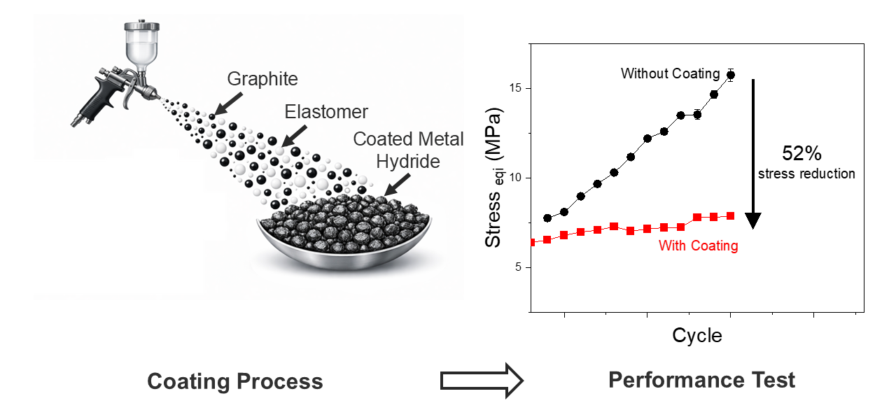
The preparation of the lab-scale sample has been reported before [42]. Briefly, 10 g of crushed HyC5 was coated with a suspension containing 1 g of EVA and 1 g of ENG dissolved in hexane (80 ml). The solvent was evaporated during mechanical stirring at 85 °C. The residual solvent was removed by heating the sample at 85 °C. The larger-scale wash-coating process was done in a household stand mixer with a heatable mixing bowl (see Figure A1). In a typical experiment, 1 kg of crushed HyC5 was coated. For the coating suspension, 100 g of EVA and 100 g of ENG were added to 2.5 L of hexane and heated to 55 °C until the EVA was dissolved (≈3 h). After the EVA had been dissolved, the HyC5 was added to the mixture, and the temperature was set to 85 °C to evaporate the solvent. The residual solvent was removed by heating the sample at 85 °C for 5 h in an electric oven. Spray-coating was performed using a commercially available paint spray pistol (Stahlwerk DG-600 ST). A larger nozzle of 1.7 mm was needed to prevent the system from being blocked. For the Spray-coating, 100 g of EVA and 100 g of ENG were dissolved in 2.5 L of cyclohexene at 80 °C, and the mixture was slowly sprayed onto 1 kg of HyC5 while manually moving the metal alloy to ensure an even coating. The solvent residue was removed after coating with a hot air flow (hot-air gun) while the sample was manually moved. The different coated samples will be referred to as HyC5+ENG+EVA-Lab, HyC5+ENG+EVA-Wash, and HyC5+ENG+EVA-Spray.
2.3. Sample Characterization
The lab-scale samples were investigated with an in-house-built Sievert-type apparatus. In addition to the hydrogen capacity, the temperature and strain were also measured in situ by attaching a strain gauge (Series M strain gauge, Type 1-LM15-6/350GE, HBM) and a thermocouple (Self-adhesive K-Type thermocouple, class 1 with a deviation limit of ±1.5 °C, Therma GmbH) to the sample holder. More information about the measurement principle and the sample holder was reported before [42].
The intermediate-scale hydrogen storage investigation was conducted at an in-house test station [43]. The measurement is based on the quantitative evaluation of the hydrogen gas mass balance during the absorption/desorption. With the known mass of the hydride material, the specific gas flow (from a gas flow meter), the gas density and temperature, and the volume of the gaseous phase, the hydrogen capacity of the sample can be calculated. The hydrogen capacity of the test system can then be calculated from the hydrogen mass balance. A commercially available pressure cylinder (Swagelok 304L-HDF4-150) was used as a sample holder (see Figure A4). Two strain gauges (Series M strain gauge, Type 1-LM15-6/350GE, HBM) have been attached to the surface of the cylinder. One was attached at the middle and one at the bottom of the cylinder, where the highest stress is expected (see Figure A5). The measured strain was converted to a pressure equivalent using a calibration curve (see Figure A10) by filling the empty cylinder with hydrogen at varying pressures and measuring the corresponding strain. Temperature control during the experiment was achieved by immersing the cylinder in a thermobath containing a 1:1 mixture of water and glycol (see Figure A6) and connecting the system to a temperature control device (Julabo FL1703). The density of the samples was measured at 20 °C with a Micrometrics AccuPyc II 1340 pycnometer with helium as sample gas, with 20 purge cycles at 1.14 bar and 30 test cycles at the same pressure. With knowledge of the sample mass, the sample density (Table A1), and the volume of the sample holder, the packing fraction can be calculated. Scanning electron microscopy (SEM) was used to characterize the coverage and morphology of the samples. The measurements were conducted with a FEI Quanta 650. The samples were attached to an aluminum pin with adhesive carbon tape and sputtered with gold before the measurements to increase conductivity.
3. Results and Discussion
3.1. Lab-Scale Measurements
To improve thermal conductivity and reduce stress on the tank walls, a coating containing 10 wt% ENG and 10 wt% EVA showed the best performance [42]. While our earlier results were conducted at the lab scale with a wash-coating process, the investigations in this work focus on scalability. Two different coating approaches have been developed in the scope of this research. The first one was the direct application of the wash-coating process on a larger scale, whereas a household stand mixer with a heatable bowl was used to stir the mixture of the metal alloy and coating suspension as the solvent slowly evaporated (Figure A1). The second method was a newly investigated approach in which the functional coating was applied by spray-coating to the surface of the metal alloy (Figure A2). To our knowledge, such an approach has not been used before in metal hydrides. Only El-Eskandarany [44] has used spraying in the context of metal hydride research, where cold spraying was used to attach nickel powder to a magnesium surface.
To investigate the long-term stability and activation behavior of the different samples, we have studied the hydrogen capacity over 50 cycles. The results are shown in Figure 1, where the sample coated with 10 wt% ENG and 10 wt% EVA at a smaller lab scale (HyC5+ENG+EVA-Lab) acts as a benchmark [42]. The cycling was conducted at 40 °C with hydrogen pressures of 40 bar for absorption and 5 bar for desorption, conditions that are compatible with possible coupling to electrolyzers or fuel cells [19,45]. The samples have been added to the sample holder without further preparation or prior contact with hydrogen. Therefore, the samples are activated and reaching full capacity during cycling. The clear performance difference between the samples investigated is evident in Figure 1. The lab-scale coated sample reaches its maximum capacity of 1.14 wt% during the 5th cycle and thus demonstrates acceptable hydrogen capacity and activation behavior.
In contrast to this benchmark sample, the performance of the larger-scale wash-coat sample is far inferior. While it reached some hydrogen capacity during the first cycle (≈0.64 wt%), it took about 20 cycles to reach its full capacity of ≈0.84 wt%, which is lower than that of the lab-scale sample. On the contrary, the spray-coated sample performed even better. It could be fully activated even during the first cycle (Figure A3) and has reached a capacity of ≈1.21 wt%. The activation behavior of the lab-scale and spray-coated samples is comparable to that of pure HyC5, which is fully activated after 3 cycles and serves as a further benchmark in Figure 1. However, it should be clarified here that the measured capacity of the pure HyC5 is not the true capacity, which is expected to be ≈1.6 wt% [40,46,47,48,49]. The Sieverts technique has limitations for samples with very fast kinetics, such as HyC5, and cannot track hydrogen absorbed in the first few seconds of the measurement. The capacity of the coated samples can be assumed to be their true capacity, given the slight influence of the coatings on the absorption kinetics and the expected hydrogen capacity, considering the additional mass of the coating.
Heat management and stress development (Figure 2) show similar tendencies. The measured peak temperatures for the lab-scale sample (≈58 °C) and the spray-coated sample (≈59 °C) are very similar, whereas the spray-coated sample's higher hydrogen capacity could account for the slightly higher measured temperature. Larger amounts of absorbed hydrogen most likely lead to more heat development during the cycling. The measured peak temperature of the wash-coated sample is ≈55 °C lower than the other two. This observation is attributed to the reduced capacity of the wash-coated sample. Another important parameter for the hydrogen storage performance, the stress development during material expansion, has also been measured for these samples. An additional set of experiments was conducted to obtain this data, in which a high solid fraction, exceeding the critical value of 0.61 [50], was applied to the different samples in the sample holder. However, due to experimental limitations [42], quantifying hydrogen capacity at higher packing fractions was no longer possible. The measured stress for both the lab-scale sample [42] and the wash-coated sample remains constant throughout the measurement at ≈4.1 MPa and ≈5.0 MPa, respectively, close to the expected equivalent stress due to the absorption pressure of 40 bar. Interestingly, the spray-coated sample shows a slightly different behavior. The measured stress remains within the same range as the other two investigated samples through cycle 12, then increases to a plateau at ≈8.0 MPa.
Figure 3 shows the morphology of the samples coated by the larger-scale wash-coating process. The images were generated using the backscatter detector, which is sensitive to changes in atomic number. The HyC5, which contains heavy metals, appears brighter than ENG or EVA. An overview image of the sample at lower magnification (Figure 3a) shows that the coating is not homogeneous. Several bright surfaces show incomplete surface coating, while others show a very dense coating. The compact coating can be seen at higher magnification (Figure 3b), where the flake-like shape of ENG is no longer visible. We assume that only partially covered particles with an accessible surface could be activated and disintegrated into a powder. Completely covered particles have been "sealed" by the coating and remain as larger particles (e.g., Figure 3c; highlighted in white) in the sample. A more complete and homogenous coating might have led to an even higher reduction in hydrogen capacity.
For comparison, the morphology of the spray-coated sample is shown in Figure 4. The overview image (Figure 4a) shows that the surface coating is more homogeneous, with only a few small, bright spots visible. These are likely very small particles from the crushing process that may not be properly embedded into the coating [19]. The most significant difference is visible at higher magnification (Figure 4b): Compared to the wash-coating process, the coating structure is much more porous, and even the individual flake-shaped ENG particles can still be identified. This suggests that the open-pored structure improves performance compared to the wash-coated samples. Hydrogen can more readily access the metal alloy particles, thereby improving both activation time and capacity. The sample was fully activated and disintegrated into a fine powder, leaving no unreacted larger particles (Figure 4c). While enhancing kinetic performance, this porous structure may also lead to a slight decline in stress compensation. Exothermic hydrogen absorption (softening the binder EVA at higher temperatures) and internal expansion, which press the individual particles against each other, lead to the formation of in-situ pellets [42]. Due to the open structure, the contact area between individual particles is not as good as in the sample HyC5+ENG+EVA-Lab, and an in-situ pellet formation, as reported in our previous work [42], is incomplete. Only some larger crumbs are formed (Figure A7a). At the same time, smaller pulverized particles might be able to pass through the coating's porous network and agglomerate, generating friction. This might explain the observed slight increase in measured stress for the spray-coated sample after a certain number of cycles (see Figure 2b).
Similar to the spray-coating approach, the pellet formation for the wash-coating process was also incomplete, and only crumps formed (Figure A7b). These observations suggest that, due to reduced capacity and slower kinetics, the cycling temperature is lower than that of the other samples investigated. However, as just mentioned, specific temperature and pressure are needed to soften the EVA coating and enable pellet formation. This incomplete pellet formation might also be the reason some degree of stress was measured (≈5.0 MPa at 40 bar hydrogen pressure) despite the much-reduced hydrogen capacity.
The results show that the wash-coating appled at a larger scale produces a denser coating than the lab-scale process. We assume this is mainly due to the coating suspension's higher viscosity. Compared to the lab-scale coating, the relative surface area of the reaction vessel for the wash-coating process was smaller. This results in much longer evaporation times for the entire solvent (a few hours) and a viscous "slurry" during the coating process.
To investigate the scaling-up approach, we have also prepared a sample with the lab scale set-up with a larger sample mass (30 g instead of 10 g) and, consequently, a larger amount of ENG and EVA for the coating while retaining the amount of solvent (75 ml), to reach the same ratio as in the larger-scale wash-coating process. This results in a coating slurry with higher viscosity than the standard approach and a longer evaporation time. The resulting sample has reduced capacity compared to the tested HyC5+ENG+EVA-Lab sample (see Figure 5). The capacity is still higher than that of the samples from the larger-scale synthesis. Different parameters, e.g., the viscosity of the coating suspension, the mixing quality, or the time required to evaporate the solvent, seem to affect the hydrogen capacity of the samples. The viscosity can therefore be only one part of the whole system, and a round-bottom flask cannot perfectly mimic the setup conditions used for the larger-scale wash-coating process.
3.2. Intermediate-Scale Measurements
The results from section 3.1 show that coating the surface of metal alloys with EVA and ENG via spray coating is a promising method to improve their hydrogen-storage performance. However, to date, the performance of the sample has been investigated only with a sample size of ≈10 g, and earlier results have shown a considerable difference in performance across the scale [51]. To gain a better understanding of a larger scale (e.g., a stationary hydrogen storage system or specialized mobile applications [52]), the performance of the samples from section 3.1 was tested with a larger sample size of ≈ 500 g. To measure this larger cylinder, we have used an in-house built test system for larger tanks [43]. Unlike the previously used Sievers apparatus, this system operates on mass flow rather than pressure differences. The resulting capacities are, therefore, not directly comparable. The slower hydrogen absorption, caused by the larger mass and cumulative hydrogen flow measurement, leads to a more precise measurement of the hydrogen capacity. As mentioned before, too-fast kinetics can lead to "capacity loss" during measurement, resulting in a lower-than-expected hydrogen capacity due to a delayed response in a Sieverts apparatus. We used a commercially available pressure cylinder for this test and attached two strain gauges. One is in the middle of the cylinder, and the other is near the bottom at the expected point of maximum stress (see Figure A5). As a benchmark, we have done two preliminary tests. In one test, the cylinder was filled about half-full with HyC5. The standard approach to filling a tank system with a metal alloy for hydrogen storage is to fill it only partly to add free volume and compensate for the expansion stress. In the second test, the cylinder was filled with HyC5 until a packing fraction of 67 % was reached, to ensure that the material's expansion stress could no longer be compensated by the interparticle volume [50]. The results will be directly compared with a measurement in which the cylinder was filled with the sample HyC5+ENG+EVA-Spray, with a high packing fraction (>67 %). This was done to reach a state in which stress development is expected under normal circumstances. The results for the intermediate-scale measurements regarding hydrogen capacity and stress development are shown in Figure 6. As a side note, we also recorded the temperature during the experiments, but due to the chosen experimental setup (a water bath to control the temperature; Figure A6), the recorded temperature did not yield reasonable results and will not be further discussed (Figure A8).
The importance of the packing fraction regarding activation, hydrogen capacity, and stress development becomes apparent. About 7 cycles are needed for the half-full sample to be fully activated. Until then, only negligible hydrogen absorption could be observed, which was mostly attributed to hydrogen in the gas phase rather than to absorption as a metal hydride. After the activation, the samples reach a capacity of ≈1.63 wt%. This value is much higher than the capacity observed in measurements with the Sievers apparatus and, as mentioned before, is consistent with the capacities reported previously for HyC5 [40,46,47,48,49]. Furthermore, although the free space of the half-filled cylinder was sufficient to compensate for potential stress development, only ≈6.0 MPa of stress was measured in both the middle and bottom parts of the cylinder. There are no "hot spots" for stress development. Interestingly, progress in stress development can also be observed during the measurement. According to Figure A9, a sudden increase in stress was observed at the start of absorption, which is mostly correlated with the hydrogen pressure during absorption. For a short time (≈16 min), the measured stress at the middle position of the cylinder is higher than at the bottom, while the reaction front travels from the top of the cylinder. After the reaction front reaches the bottom of the cylinder, the stress at the bottom begins to exceed that in the middle because frictional effects are higher than in the middle [20].
The performance is reduced if the sample lacks free volume to compensate for the expansion during hydrogen absorption. Not only are more cycles needed to activate the sample (10 cycles), but the resulting capacity is also reduced to only 1.18 wt%. We assume this is a direct consequence of the high packing fraction and the resulting internal stress of the sample. The observation that stress reduces the capacity of metal hydrides has been reported previously [53,54]. After 20 cycles, the packed sample has reached a stress of 13.7 MPa at the middle of the cylinder and up to 15.7 MPa at the bottom. This internal stress seems high enough that the β-phase cannot fully form, reducing the overall hydrogen capacity.
The performance of HYC5+ENG+EVA-Spray could be reproduced in this intermediate-scale experiment. Activating the spray-coated sample even faster than the pure metal alloy was possible. It was fully activated after 5 cycles and reached ≈1.18 wt%, the same hydrogen capacity as the filled cylinder, despite additional mass in ENG and EVA. The measured stress started at ≈4 MPa, which correlates to the hydrogen pressure during the absorption (40 bar). Stress increases with the number of cycles but reaches a plateau after 17 cycles at 7.4 MPa in the middle section of the cylinder and 7.8 MPa at the bottom. This is even a slight reduction compared to the small-scale experiment from section 3.1. We assume this difference is due to differences in shape between the lab-scale and intermediate-scale sample holders. The commercially available cylinder from the intermediate-scale experiments is bulkier than the sample holder of the lab-scale measurements, and a slim sample holder is more prone to stress development [24].
4. Conclusions
A commercially available RT-metal hydride has been coated with 10 wt% ENG and 10 wt% EVA. Previous investigations have shown that this mixture could compensate for the expansion stress and improve the thermal conductivity [42], two of the main challenges for hydrogen storage in metal hydrides. No stress could be measured outside the sample holder, and the measured peak temperature (used as a heat management qualifier) could be reduced by 2 °C while retaining acceptable hydrogen capacity. The aim was now to find a method that could be easily scaled to the kilogram or even larger ranges. This will prepare the sample much more easily and cost-effectively.
A wash-coating approach has been investigated before and shown promising results in a lab-scale synthesis, but it has been less successful during the scaling process. The capacity of samples prepared by wash-coating at a larger scale decreased significantly (from 1.14 wt% to 0.84 wt%), and more time was required for activation (5 cycles vs. 20 cycles). Further investigations have shown that the performance decline might have been caused by slow solvent evaporation and the formation of a very viscous slurry during large-scale synthesis. This leads to dense coating and slow kinetics for the sample. Spray-coating was a promising alternative for large-scale coating. The hydrogen capacity was even larger than that of the other investigated samples (≈1.21 wt%), while it compensated for most of the stress caused by the hydrogen absorption (≈ 8 MPa stress equivalent at 40 bar hydrogen pressure was measured). Another aspect of this investigation was to compare results from a lab-scale sample (a few grams) with those from an intermediate-scale measurement (≈0.5 kg). Such a comparison has shown a greater impact on a commercial hydrogen storage system that must store at least several kilograms of hydrogen. The promising lab-scale results of the spray-coated sample could be reproduced at the larger intermediate scale. The spray-coated sample compensated for the expansion stress (7.8 MPa, compared to 15.7 MPa for an uncoated sample at the bottom of the sample holder) while retaining acceptable hydrogen capacity at ≈1.18 wt%. While there may still be room for improvement in the wash-coating approach (e.g., optimizing the stirrer setup), the spray-coating approach has shown superior performance. The coating process was faster, the samples required fewer activation cycles (5), and the hydrogen capacity was higher (1.18 wt% even after 50 cycles). This wash-coating method offers significant potential for scaling up and operation at a several-kilogram scale.
Author Contributions
Conceptualization, J.W.; methodology, J.W.; validation, J.W and J.P.; formal analysis, J.W; investigation, J.W; resources, J.P, T.K and J, J; data curation, J.J and J.P; writing—original draft preparation, J.W.; writing—review and editing, J.W, J.P, P.K, E.W, T.K, J.J; visualization, J.W; supervision, J.P and J.J; project administration, J.P, J.J, and T.K; funding acquisition, T.K and J.J All authors have read and agreed to the published version of the manuscript.
Funding
The authors gratefully acknowledge the funding by Bundesministerium für Wirtschaft und Klimaschutz in the frame of the "HyReflexS "project (Funding code: 03El3020A and 03EI3020C). This research work is also in the frame of the project Digi-HyPro, funded by dtec.bw – Digitalization and Technology Research Center of the Bundeswehr, which the authors gratefully acknowledge. dtec.bw is funded by the European Union – NextGenerationEU. The authors also acknowledge the RYC2024-048171-I funded by MICIU/AEI /10.13039/501100011033 and FSE+.
Data Availability Statement
The raw data supporting the conclusions of this article will be made available by the authors on request.
Conflicts of Interest
The authors declare no conflicts of interest.
Abbreviations
The following abbreviations are used in this manuscript:
| ENG | Expanded Natural Graphite |
| EVA | Ethylene-Vinyl Acetate Copolymer |
| LCA | Life-Cycle Assessment |
| SEM | Scanning Electron Microscopy |
| RT | room-temperature |
Appendix A
Figure A1.
Image of the experimental set-up used for the larger-scale wash-coating process in a household stand mixer with a heatable bowl.
Figure A1.
Image of the experimental set-up used for the larger-scale wash-coating process in a household stand mixer with a heatable bowl.

Figure A2.
Comparison of the metal alloy at the beginning of the spray-coating process (left) and after the coating process is finished (right).
Figure A2.
Comparison of the metal alloy at the beginning of the spray-coating process (left) and after the coating process is finished (right).

Figure A3.
Activation behavior of HyC5+ENG+EVA-Spray. The sample could be activated during the first cycle. The kinetic behavior of the sample remains stable across consecutive cycles.
Figure A3.
Activation behavior of HyC5+ENG+EVA-Spray. The sample could be activated during the first cycle. The kinetic behavior of the sample remains stable across consecutive cycles.

Figure A4.
Image of the Swagelog tank used for the intermediate-scale hydrogen storage investigation. The sensors on the surface of the Swagelog tank are covered with a watertight coating (in red).
Figure A4.
Image of the Swagelog tank used for the intermediate-scale hydrogen storage investigation. The sensors on the surface of the Swagelog tank are covered with a watertight coating (in red).

Figure A5.
Schematic image of the used Swagelog cylinder for the intermediate size measurements. The positions of the attached stress sensors at the middle of the sample holder ("Mid") and close to the bottom of the sample holder ("Bottom") are highlighted.
Figure A5.
Schematic image of the used Swagelog cylinder for the intermediate size measurements. The positions of the attached stress sensors at the middle of the sample holder ("Mid") and close to the bottom of the sample holder ("Bottom") are highlighted.

Figure A6.
During the measurements, the sample cylinder is immersed in a thermobath containing a 1:1 water/glycol mixture and connected to a Julabo FL1703 temperature controller.
Figure A6.
During the measurements, the sample cylinder is immersed in a thermobath containing a 1:1 water/glycol mixture and connected to a Julabo FL1703 temperature controller.


Table A1.
Density of the coated samples.
| Sample | Density (g/cm³) |
|---|---|
| HyC5+ENG+EVA-Lab | 3.16 |
| HyC5+ENG+EVA-Wash | 3.87 |
| HYC5+ENG+EVA-Spray | 3.74 |
Figure A7.
HyC5+ENG-EVA-Spray after cycling (a). The sample has not formed a complete pellet; only several smaller crumps have formed. HyC5-ENG-EVA-Wash also showed incomplete pellet formation (b).
Figure A7.
HyC5+ENG-EVA-Spray after cycling (a). The sample has not formed a complete pellet; only several smaller crumps have formed. HyC5-ENG-EVA-Wash also showed incomplete pellet formation (b).

Figure A8.
The measured cylinder temperature was filled to half-full volume with HyC5 outside the sample holder. Using a water-glycol mixture has led to a much faster temperature transfer than electric heating with an oven during the lab-scale experiments. The temperature changes during the larger-scale experiments are therefore not significant.

Figure A9.
Stress behavior during hydrogen absorption in intermediate-scale experiments during one absorption cycle. The tank was filled with HyC5.
Figure A9.
Stress behavior during hydrogen absorption in intermediate-scale experiments during one absorption cycle. The tank was filled with HyC5.

Figure A10.
Calibration of the strain gauges attached to the larger Swagelog cylinder to convert the measured strain [µm/m] into a pressure equivalent [bar]. For this measurement, the empty Swagelog cylinder was filled with hydrogen at varying pressures. The data show a linear relationship between strain and the equivalent pressure.

References
- Hydrogen Europe Research, Position Paper: Advancing Hydrogen Technologies. 2024. Available online: https://hydrogeneuroperesearch.eu.
- New Zeeland Hydrogen Council, Hydrogen Action Plan. 2024. Available online: https://www.nzhydrogen.org.
- Australian Government, National Hydrogen Strategy 2024. 2024. Available online: https://www.dcceew.gov.au/energy/publications/australias-national-hydrogen-strategy.
- Liu, W.; Wan, Y.; Xiong, Y.; Gao, P. Green Hydrogen Standard in China: Standard and Evaluation of Low-Carbon Hydrogen, Clean Hydrogen, and Renewable Hydrogen. Int. J. Hydrogen Energy 2022, 47, 24584–24591. [Google Scholar] [CrossRef]
- Mahajan, D.; Tan, K.; Venkatesh, T.; Kileti, P.; Clayton, C.R. Hydrogen Blending in Gas Pipeline Networks—A Review. Energies (Basel). 2022, 15, 3582. [Google Scholar] [CrossRef]
- Bararzadeh Ledari, M.; Khajehpour, H.; Akbarnavasi, H.; Edalati, S. Greening Steel Industry by Hydrogen: Lessons Learned for the Developing World. Int. J. Hydrogen Energy 2023, 48, 36623–36649. [Google Scholar] [CrossRef]
- Sartbaeva, A.; Kuznetsov, V.L.; Wells, S.A.; Edwards, P.P. Hydrogen Nexus in a Sustainable Energy Future. Energy Environ. Sci. 2008, 1, 79. [Google Scholar] [CrossRef]
- Rivarolo, M.; Riveros-Godoy, G.; Magistri, L.; Massardo, A.F. Clean Hydrogen and Ammonia Synthesis in Paraguay from the Itaipu 14 GW Hydroelectric Plant. ChemEngineering 2019, 3, 87. [Google Scholar] [CrossRef]
- Orlova, S.; Mezeckis, N.; Vasudev, V.P.K. Compression of Hydrogen Gas for Energy Storage: A Review. Latvian Journal of Physics and Technical Sciences 2023, 60, 4–16. [Google Scholar] [CrossRef]
- Zhang, F.; Zhao, P.; Niu, M.; Maddy, J. The Survey of Key Technologies in Hydrogen Energy Storage. Int. J. Hydrogen Energy 2016, 41, 14535–14552. [Google Scholar] [CrossRef]
- Zhang, T.; Uratani, J.; Huang, Y.; Xu, L.; Griffiths, S.; Ding, Y. Hydrogen Liquefaction and Storage: Recent Progress and Perspectives. Renewable and Sustainable Energy Reviews 2023, 176, 113204. [Google Scholar] [CrossRef]
- Adler, E.J.; Martins, J.R.R.A. Hydrogen-Powered Aircraft: Fundamental Concepts, Key Technologies, and Environmental Impacts. Progress in Aerospace Sciences 2023, 141, 100922. [Google Scholar] [CrossRef]
- Ali, N.A.; Sazelee, N.A.; Ismail, M. An Overview of Reactive Hydride Composite (RHC) for Solid-State Hydrogen Storage Materials. Int. J. Hydrogen Energy 2021, 46, 31674–31698. [Google Scholar] [CrossRef]
- Xu, Y.; Zhou, Y.; Li, Y.; Hao, Y.; Wu, P.; Ding, Z. Recent Advances in the Preparation Methods of Magnesium-Based Hydrogen Storage Materials. Molecules 2024, 29. [Google Scholar] [CrossRef]
- Klopčič, N.; Grimmer, I.; Winkler, F.; Sartory, M.; Trattner, A. A Review on Metal Hydride Materials for Hydrogen Storage. J. Energy Storage 2023, 72, 108456. [Google Scholar] [CrossRef]
- Stahlkopf, G.; Passing, M.; Puszkiel, J.A.; Moosmann, J.; Beckmann, F.; Warfsmann, J.; Karimi, F.; Kulvait, V.; Klassen, T.; Jepsen, J. Insights on Mechanical and Morphological Metal Hydride Powder Characteristics during Hydrogen Interaction and Stress Mitigation Strategies for Hydrogen Storage Vessels. Int. J. Hydrogen Energy 2026, 215. [Google Scholar] [CrossRef]
- Charlas, B.; Gillia, O.; Doremus, P.; Imbault, D. Experimental Investigation of the Swelling/Shrinkage of a Hydride Bed in a Cell during Hydrogen Absorption/Desorption Cycles. Int. J. Hydrogen Energy 2012, 37, 16031–16041. [Google Scholar] [CrossRef]
- Okumura, M.; Ikado, A.; Saito, Y.; Aoki, H.; Miura, T.; Kawakami, Y. Pulverization Mechanism of Hydrogen Storage Alloys on Microscale Packing Structure. Int. J. Hydrogen Energy 2012, 37, 10715–10723. [Google Scholar] [CrossRef]
- Puszkiel, J.A.; Neves, A.M.; Warfsmann, J.; Krause, P.S.; Kaufmann, T.F.J.; Robelo Hoberg, A.; Hegen, O.; Kötter, A.; Klassen, T.; Jepsen, J. On the Hydrogen Storage Properties and Life Cycle Evaluation of a Room Temperature Hydride for Scale-up Applications: The Case of an AB2-Alloy. Int. J. Hydrogen Energy 2025, 118, 482–499. [Google Scholar] [CrossRef]
- Okumura, M.; Ikado, A.; Saito, Y.; Matsushita, Y.; Aoki, H.; Kiwakami, Y. The Stress Developed on the Side Wall of the Pressure Vessel for the Packed Bed of the Hydrogen Storage Alloy and the Change in the Packing State. Journal of the Japan Institute of Energy 2021, 100, 5–12. [Google Scholar] [CrossRef]
- Qin, F.; Chen, J.; Chen, Z. The Hydriding-Dehydriding Characteristics of La0.6Y0.4Ni4.8Mn0.2 and Their Influences in the Surface Strain on Small-Scale, Thin-Wall and Vertical Containers. Mater. Des. 2008, 29, 1926–1933. [Google Scholar] [CrossRef]
- Askri, F.; Bensalah, M.; Jemi, A.; Bennasrallah, S. Optimization of Hydrogen Storage in Metal-Hydride Tanks. Int. J. Hydrogen Energy 2009, 34, 897–905. [Google Scholar] [CrossRef]
- Saito, T.; Suwa, K.; Kawamura, T. Influence of Expansion of Metal Hydride during Hydriding-Dehydriding Cycles; 1997; Vol. 253. [Google Scholar]
- Charlas, B.; Gillia, O.; Doremus, P.; Imbault, D. Experimental Investigation of the Swelling/Shrinkage of a Hydride Bed in a Cell during Hydrogen Absorption/Desorption Cycles. Int. J. Hydrogen Energy 2012, 37, 16031–16041. [Google Scholar] [CrossRef]
- Cuscueta, D.J.; Silin, N.; Melnichuk, M. Stress Reduction in a Hydride Container by the Addition of a Glidant Agent. Int. J. Hydrogen Energy 2020, 45, 27452–27456. [Google Scholar] [CrossRef]
- Cao, H.; Georgopanos, P.; Capurso, G.; Pistidda, C.; Weigelt, F.; Chaudhary, A.-L.; Filiz, V.; Tseng, J.-C.; Wharmby, M.T.; Dornheim, M.; et al. Air-Stable Metal Hydride-Polymer Composites of Mg(NH2)2–LiH and TPXTM. Mater. Today Energy 2018, 10, 98–107. [Google Scholar] [CrossRef]
- Heubner, F.; Pohlmann, C.; Mauermann, S.; Kieback, B.; Röntzsch, L. Mechanical Stresses Originating from Metal Hydride Composites during Cyclic Hydrogenation. Int. J. Hydrogen Energy 2015, 40, 10123–10130. [Google Scholar] [CrossRef]
- Davis Cortina, M.; Romero de Terreros Aramburu, M.; Neves, A.M.; Hurtado, L.; Jepsen, J.; Ulmer, U. The Integration of Thermal Energy Storage Within Metal Hydride Systems: A Comprehensive Review. Inorganics (Basel). 2024, 12, 313. [Google Scholar] [CrossRef]
- Dornheim, M.; Baetcke, L.; Akiba, E.; Ares, J.R.; Autrey, T.; Barale, J.; Baricco, M.; Brooks, K.; Chalkiadakis, N.; Charbonnier, V.; et al. Research and Development of Hydrogen Carrier Based Solutions for Hydrogen Compression and Storage. Progress in Energy 2022, 4. [Google Scholar] [CrossRef]
- Bellosta von Colbe, J.; Ares, J.R.; Barale, J.; Baricco, M.; Buckley, C.; Capurso, G.; Gallandat, N.; Grant, D.M.; Guzik, M.N.; Jacob, I.; et al. Application of Hydrides in Hydrogen Storage and Compression: Achievements, Outlook and Perspectives. Int. J. Hydrogen Energy 2019, 44, 7780–7808. [Google Scholar] [CrossRef]
- Scarpati, G.; Puszkiel, J.A.; Warfsmann, J.; Karimi, F.; Jannelli, E.; Pistidda, C.; Klassen, T.; Jepsen, J. Comprehensive Overview of the Effective Thermal Conductivity for Hydride Materials: Experimental and Modeling Approaches. Energies (Basel). 2025, 18, 194. [Google Scholar] [CrossRef]
- Ye, J.; Li, Z.; Zhang, L.; Wang, S.; Jiang, L. Measurement and the Improvement of Effective Thermal Conductivity for a Metal Hydride Bed – a Review. RSC Adv. 2022, 12, 25722–25743. [Google Scholar] [CrossRef]
- Srinivasa Murthy, S. Heat and Mass Transfer in Solid State Hydrogen Storage: A Review. J. Heat Transfer 2012, 134. [Google Scholar] [CrossRef]
- Satya Sekhar, B.; Lototskyy, M.; Kolesnikov, A.; Moropeng, M.L.; Tarasov, B.P.; Pollet, B.G. Performance Analysis of Cylindrical Metal Hydride Beds with Various Heat Exchange Options. J. Alloys Compd. 2015, 645, S89–S95. [Google Scholar] [CrossRef]
- Afzal, M.; Sharma, P. Design of a Large-Scale Metal Hydride Based Hydrogen Storage Reactor: Simulation and Heat Transfer Optimization. Int. J. Hydrogen Energy 2018, 43, 13356–13372. [Google Scholar] [CrossRef]
- Costamagna, M.; Barale, J.; Carbone, C.; Luetto, C.; Agostini, A.; Baricco, M.; Rizzi, P. Environmental and Economic Assessment of Hydrogen Compression with the Metal Hydride Technology. Int. J. Hydrogen Energy 2022, 47, 10122–10136. [Google Scholar] [CrossRef]
- Zhang, Z.; Sato, K.; Nagasaki, Y.; Tsuda, M.; Miyagi, D.; Komagome, T.; Tsukada, K.; Hamajima, T.; Ishii, Y.; Yonekura, D. Continuous Operation in an Electric and Hydrogen Hybrid Energy Storage System for Renewable Power Generation and Autonomous Emergency Power Supply. Int. J. Hydrogen Energy 2019, 44, 23384–23395. [Google Scholar] [CrossRef]
- McCabe, W.L.; Smith, J.C.; Harriot, P. Unit Operations of Chemical Engineering, 5th ed.; New York, 1993. [Google Scholar]
- Afzal, M.; Mane, R.; Sharma, P. Heat Transfer Techniques in Metal Hydride Hydrogen Storage: A Review. Int. J. Hydrogen Energy 2017, 42, 30661–30682. [Google Scholar] [CrossRef]
- Barale, J.; Nastro, F.; Violi, D.; Rizzi, P.; Luetto, C.; Baricco, M. A Metal Hydride Compressor for a Small Scale H2 Refuelling Station. Int. J. Hydrogen Energy 2023, 48, 34105–34119. [Google Scholar] [CrossRef]
- Odenweller, A.; Ueckerdt, F. The Green Hydrogen Ambition and Implementation Gap. Nat. Energy 2025, 10, 110–123. [Google Scholar] [CrossRef]
- Warfsmann, J.; Puszkiel, J.A.; Passing, M.; Krause, P.S.; Wienken, E.; Taube, K.; Klassen, T.; Pistidda, C.; Jepsen, J. Applying Wash Coating Techniques for Swelling-Induced Stress Reduction and Thermal Improvement in Metal Hydrides. J. Alloys Compd. 2023, 950. [Google Scholar] [CrossRef]
- Capurso, G.; Schiavo, B.; Jepsen, J.; Lozano, G.; Metz, O.; Saccone, A.; De Negri, S.; Bellosta von Colbe, J.M.; Klassen, T.; Dornheim, M. Development of a Modular Room-Temperature Hydride Storage System for Vehicular Applications. Applied Physics A 2016, 122, 236. [Google Scholar] [CrossRef]
- El-Eskandarany, M.S.; Ali, N.; Banyan, M.; Al-Ajmi, F. Cold Gas-Dynamic Spray for Catalyzation of Plastically Deformed Mg-Strips with Ni Powder. Nanomaterials 2021, 11, 1169. [Google Scholar] [CrossRef]
- Puszkiel, J.; Covarrubis Guraneros, M.; Fleming, L.; Kaufmann, T.F.J.; Krause, P.; Warfsmann, J.; Wienken, E.; Wildner, L.; Kutzner, H.; Schulze, M.; et al. Hydrogen in Stationary Applications: Coupling the Electricity, Gas and Mobility Sectors (Digi-HyPro). In Detec-Paper (in Press).
- Herbrig, K.; Röntzsch, L.; Pohlmann, C.; Weißgärber, T.; Kieback, B. Hydrogen Storage Systems Based on Hydride-Graphite Composites: Computer Simulation and Experimental Validation. Int. J. Hydrogen Energy 2013, 38, 7026–7036. [Google Scholar] [CrossRef]
- Eberle, U.; Felderhoff, M.; Schüth, F. Chemical and Physical Solutions for Hydrogen Storage. Angewandte Chemie - International Edition 2009, 48, 6608–6630. [Google Scholar] [CrossRef]
- Heubner, F.; Hilger, A.; Kardjilov, N.; Manke, I.; Kieback, B.; Gondek, Ł.; Banhart, J.; Röntzsch, L. In-Operando Stress Measurement and Neutron Imaging of Metal Hydride Composites for Solid-State Hydrogen Storage. J. Power Sources 2018, 397, 262–270. [Google Scholar] [CrossRef]
- Kölbig, M.; Bürger, I.; Linder, M. Characterization of Metal Hydrides for Thermal Applications in Vehicles below 0 °C. Int. J. Hydrogen Energy 2019, 44, 4878–4888. [Google Scholar] [CrossRef]
- Nasako, K.; Ito, Y.; Hiro, N.; Osumi, M. Stress on a Reaction Vessel by the Swelling of a Hydrogen Absorbing Alloy; 1998; Vol. 264. [Google Scholar]
- Jensen, E.H.; Dornheim, M.; Sartori, S. Scaling up Metal Hydrides for Real-Scale Applications: Achievements, Challenges and Outlook. Inorganics (Basel). 2021, 9. [Google Scholar] [CrossRef]
- Yartys, V.A.; Lototskyy, M.V.; Tolj, I.; von Colbe, J.B.; Denys, R.V.; Davids, M.W.; Nyamsi, S.N.; Swanepoel, D.; Berezovets, V.V.; Zavaliy, I.Yu.; et al. HYDRIDE4MOBILITY: An EU Project on Hydrogen Powered Forklift Using Metal Hydrides for Hydrogen Storage and H2 Compression. J. Energy Storage 2025, 109, 115192. [Google Scholar] [CrossRef]
- Haas, I.; Scutjrr, E. The Effect of Mechanical Stress on the Absoprtion of Hydrogen by Metal Hydrides; 1991; Vol. 16. [Google Scholar]
- Charlas, B.; Chaise, A.; Gillia, O.; Doremus, P.; Imbault, D. Investigation of Hydride Powder Bed Swelling and Shrinking during Hydrogen Absorption/Desorption Cycles under Different Compressive Stresses. J. Alloys Compd. 2013, 580. [Google Scholar] [CrossRef]
Figure 1.
Comparison of the hydrogen capacity for the pure HyC5 (pink), HyC5+10wt%ENG+10wt%EVA samples for the lab-scale wash-coating process [42] (black) to the larger-scale wash-coating process (red) and the spray-coated samples (green).
Figure 1.
Comparison of the hydrogen capacity for the pure HyC5 (pink), HyC5+10wt%ENG+10wt%EVA samples for the lab-scale wash-coating process [42] (black) to the larger-scale wash-coating process (red) and the spray-coated samples (green).

Figure 2.
Comparison of the measured peak temperature in the absorption step (a) and the measured equivalent stress outside the sample holder (b). The conditions for the measurements were set to 40 °C and 40 bar for the absorption and at 40 °C and 5 bar for the desorption.
Figure 2.
Comparison of the measured peak temperature in the absorption step (a) and the measured equivalent stress outside the sample holder (b). The conditions for the measurements were set to 40 °C and 40 bar for the absorption and at 40 °C and 5 bar for the desorption.

Figure 3.
Comparison of SEM images of HyC5+ENG+EVA-Wash. The samples are shown before cycling at lower (a) and higher magnification (b). The sample after cycling is also shown (c; larger unreacted particles are highlighted in white).
Figure 3.
Comparison of SEM images of HyC5+ENG+EVA-Wash. The samples are shown before cycling at lower (a) and higher magnification (b). The sample after cycling is also shown (c; larger unreacted particles are highlighted in white).

Figure 4.
Comparison of SEM images of HyC5+ENG+EVA-Spray. The samples are shown before cycling at lower (a) and higher magnification (b). The sample after cycling is also shown (c).
Figure 4.
Comparison of SEM images of HyC5+ENG+EVA-Spray. The samples are shown before cycling at lower (a) and higher magnification (b). The sample after cycling is also shown (c).

Figure 5.
Comparison of the hydrogen capacity for the samples coated in the before applied lab-scale approach (black), the modified lab scale approach with higher viscosity of the coating suspension (blue), and the Larger-Scale Wash-coating approach (red).
Figure 5.
Comparison of the hydrogen capacity for the samples coated in the before applied lab-scale approach (black), the modified lab scale approach with higher viscosity of the coating suspension (blue), and the Larger-Scale Wash-coating approach (red).

Figure 6.
Results for the intermediate-scale measurements (a: capacity; b: stress) with the cylinder complelty filled with HyC5 (black; packing fraction >67 %), a half-filled cylinder (green; packing fraction ≈33 %), and the Spray-coated sample HyC5+ENG+EVA-Spray (red, packing fraction >67 %). Due to technical problems, the stress data for the completely filled sample holder with HyC5 durig the cycles 1 to 8 was not recorded.

Disclaimer/Publisher’s Note: The statements, opinions and data contained in all publications are solely those of the individual author(s) and contributor(s) and not of MDPI and/or the editor(s). MDPI and/or the editor(s) disclaim responsibility for any injury to people or property resulting from any ideas, methods, instructions or products referred to in the content. |
© 2026 by the authors. Licensee MDPI, Basel, Switzerland. This article is an open access article distributed under the terms and conditions of the Creative Commons Attribution (CC BY) license (http://creativecommons.org/licenses/by/4.0/).
Copyright: This open access article is published under a Creative Commons CC BY 4.0 license, which permit the free download, distribution, and reuse, provided that the author and preprint are cited in any reuse.


