Submitted:
23 March 2026
Posted:
24 March 2026
You are already at the latest version
Abstract
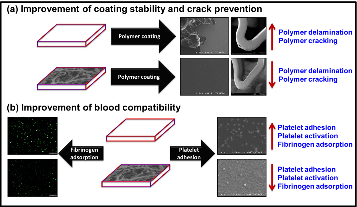
Commercially available drug-eluting stents still suffer from poor blood compatibility, polymer coating delamination, cracking and lack of stability during and after stent implantation that led to adverse events such as stent thrombosis and in-stent restenosis. This article highlights the advantages of using silicon nanofilament (SiNf) as an interface between stent surface and drug-in-polymer coating or bloodstream. The SiNf was successfully formed on the surface of Co-Cr substrate via one-step simple method. The morphology of the filaments showed nanosized structures with nano-gaps between the filaments. After coating the nanofilaments with a mixture of sirolimus and poly(D,L-lactide), an interlocking mechanism was established in which the coating penetrates the nano-gapes between the filaments. Therefore, the presence of SiNf enhanced the coating stability with no coating delamination whereas, the control substrate presented 97% of coating delamination. For stent application, the SRL-in-PDLLA matrix was coated on stent platform with smooth and uniform morphology without webbing between stent struts. After stent ballooning, the control stent presented cracking and peeling of the polymer coating from the surface whereas, the SiNf-modified stent did not show any sign of these unfavorable defects. Moreover, the platelet adhesion on the SiNf surface showed a lower number with round shape morphology compared to control Co-Cr. This suggests that modifying the substrates with SiNf could act as a universal coating for reinforcing the polymer coating stability, prevent coating defects that accompany stent ballooning, and improve the blood compatibility of the material surfaces that could have various applications to medical implants and devices.
Keywords:
silicon nanofilament
; coating stability
; coating delamination
; crack prevention
; blood compatibility
; drug-eluting stents
1. Introduction
Cardiovascular diseases are considered as one of the main cause of death all over the world especially, atherosclerosis which is the deposition and accumulation of lipids especially cholesterol around the artery walls leading to narrowing of vascular artery [1]. Several kinds of stents, such as bare metal stent (BMS), drug-eluting stent (DES), and fully bioabsorbable stents, have been used to treat atherosclerosis [2]. Balloon-expandable stents are implanted to save the life of millions of patients every year [3]. However, BMS have shown high restenosis rate of up to 40%. It has proved its effectiveness to reduce in-stent restenosis rate found after the deployment of drug-eluting stents [4,5,6]. DES is made of three main components: (i) metal, (ii) polymer(s), and (iii) drug(s).
Cobalt−Chromium (Co−Cr) alloys that belong to ASTM standards have been extensively used in various biomedical implants and devices including stents [7]. Several kinds of polymers are applied to fabricate stent to control the drug release, such as non-degradable or biodegradable polymers. Biodegradable polymers demonstrated the applicability over the non-degradable because of the inflammation results from permanent contact of non-degradable polymers with tissue [8,9]. Sirolimus and paclitaxel are examples of anti-proliferative drugs used for stent fabrications as they can inhibit smooth muscle proliferation and decrease the incidence of stent restenosis [10].
For polymer-based drug-eluting stents, several studies demonstrated that after stent expansion, several coating defects such as polymer cracking, detachment and delamination form the stent surface were observed, which accelerate the drug release, and increase the possibility of in-stent restenosis, inflammation, and/or late thrombosis [11,12,13]. According to Bedair et al., surface modification using polymer brushes (hydrophilic or hydrophobic) provided a way to improve the adhesion between stent surface and polymer coating [14,15,16]. However, these methods consume a lot of time to fabricate such brushes on the metal surface. In addition, after the degradation of biodegradable polymer, Co-Cr will be in permanent contact with the blood and soft tissue. This alloy suffers from the adsorption of blood proteins, adhesion, and activation of platelets leading to thrombosis formation [14,17]. In this regard, the need to find an easy and cheap method to fabricate a blood compatible surface and to solve the coating defects at the same time which represent challenge to fulfill our goal.
In this work, we report an easy, low cost and effective multifunctional methodology for improving blood compatibility, increasing the roughness value, increasing the surface area, enhancing the drug-in-polymer coating stability, and preventing the crack formation of polymer-based drug-eluting stents through the formation of silicon nanofilament (SiNf) on Co-Cr surfaces. This strategy could be promisingly applied for various biomedical implants and devices.
2. Materials and Methods
2.1. Materials
Minitubes Co., (Rue Jean Vaujany, France) supplied cobalt-chromium (Co–Cr, CC, 1 × 1 cm2) plates. Stent-Type Co-Cr (diameter: 1.8 mm, length: 18 mm) were obtained from Bioalpha Inc. (Korea). Methyltrichlorosilane (MTCS), sodium dodecyl sulfate (SDS), glutaraldehyde and anhydrous toluene were purchased from Sigma Aldrich (Korea). Sirolimus (SRL), and poly(D,L-lactide) (PDLLA, 75:25, 110 kDa) were purchased from LC laboratories (Woburn, USA), and Lakeshore Biomaterials, Inc. (Birmingham, USA), respectively. Methylene chloride, ethanol, and 1,4-dioxane were purchased from Daejung chemicals Co. (Korea). All the reagents were used as received without further purification.
2.2. Pretreatment for Co–Cr Substrate
The Co–Cr samples were mechanically polished as previously described [14]. Briefly, the Co–Cr plates were mechanically grinded by silicon carbide papers followed by cloth polished using 0.3 µm alumina suspensions for 8 minutes each. The polished Co–Cr substrates were washed using deionized water, ethanol and acetone for 20 minutes each. Prior to the deposition, the Co–Cr specimens were further activated using oxygen plasma for 5 minutes.
2.3. Silicon Nanofilament Formation on Co–Cr Specimens
The oxygen plasma treated Co–Cr samples were placed in Teflon-coated closed chamber and immersed in 200 ml of anhydrous toluene at 33-35% of humidified nitrogen (Figure S1). Then, 200 µl of MTCS was injected into the chamber using long-needle and the reaction continued for 1.5 h under 200 rpm stirring at room temperature. At the end of the reaction, the SiNf-modified substrates were taken out and washed with toluene, ethanol, and ethanol/water (1:1, v/v) three times each. The samples were dried using nitrogen gas and annealed at 120 ˚C for two hours. Finally, the samples were stored under vacuum until used and coded as CC-SiNf.
2.4. Surface Characterization
The chemical functional groups on the surface of Co-Cr were studied using attenuated total reflectance-Fourier transform infrared (FTIR-4100 instrument, ATR PRO450-S, JASCO Corporation, Tokyo, Japan). The elemental compositions of the Co-Cr and CC-SiNf surfaces were calculated using X-ray photoelectron spectroscopy (XPS; S-Probe, Surface Science Co., USA), spot size (100 µm × 100 µm), and survey scans (0–1000 eV). Static water contact angle measurements were determined using DGD Fast/60 contact angle meter (GBX, New Technologies Development, France) through the addition of 2.5 µL of deionized water using micro pipette onto different areas of the substrate surface for ten times and the average values were calculated. Surface morphologies of flat and stent-type Co-Cr, CC-SiNf, and CC-SiNf-PDLLA/SRL were watched using field emission-scanning electron microscope (FE-SEM, Hitachi, S4200, Japan). The topography and the roughness of flat Co-Cr and CC-SiNf substrates were visualized using atomic force microscope (AFM) using XE-100 (Park system, Korea) under a tapping mode (10 µm × 10 µm) at room temperature. The root mean square (RMS) roughness values were calculated from the average of three spots on three different samples.
2.5. Drug-in-Polymer Coating on Flat and Stent-Type Co–Cr Substrates
A solution of PDLLA containing SRL (0.4 wt%, 60:40 wt%) was prepared by dissolving 19.9 mg of PDLLA and 13.3 mg of SRL in 8.31 g of methylene chloride/dioxane (1:1, v/v) until a homogenous solution is obtained. The prepared solution were ultrasonic spray coated on flat and stent-type Co–Cr substrates as previously mentioned [18,19]. Finally, the PDLLA/SRL coated Co–Cr substrates were dried in vacuum chamber overnight and coded as CC//PDLLA/SRL, and CC-SiNf//PDLLA/SRL, respectively.
2.6. In Vitro Coating Stability Under Circulating Buffer Solution
Both CC//PDLLA/SRL and CC-SiNf//PDLLA/SRL flat substrates were inserted into 10 mm diameter silicon tube. Rate controller apparatus (100 rpm) circulated a buffer solution of PBS (pH 7.4) for 30 days. The samples were taken out of the silicon tube, washed with deionized water three times, and dried under vacuum. The surface morphology of PDLLA/SRL coating after circulation test was examined using FE-SEM.
2.7. In Vitro Stent Balloon Inflation
Both CC//PDLLA/SRL and CC-SiNf//PDLLA/SRL stents were mounted onto angioplasty balloon and dilated to 3 mm at 10 atm pressure for 30 seconds. The morphologies of the expanded PDLLA/SRL coated stents were studied using FE-SEM.
2.8. Fibrinogen Adsorption
The control and SiNf-modified Co-Cr substrates were prewashed with phosphate buffer saline (PBS) solution followed by immersion in fibrinogen solution with a concentration of 100 µg/ml for 1 h at 37 ˚C. The samples were washed with 1 ml of PBS solution three times. For quantitative analysis, 400 μl of 5% SDS solution was used to detach the adsorbed fibrinogen overnight. Then, 100 μl of the SDS/fibrinogen solution were mixed with 100 μl of Micro-BCA solution in 96-well plate. Finally, the plate was kept at 37 ˚C for 2 h followed by UV measurements at 562 nm. For qualitative analysis, fluorescent fibrinogen was used following the same protocol and the images were captured using fluorescence microscopy (Olympus, Tokyo, Japan).
2.9. Platelet Adhesion and Morphology
To study the effect of superhydrophobic property of SiNf on the platelet adhesion, the control Co-Cr and CC-SiNf substrates were sterilized under UV for 1 h. The number of platelets in platelet-rich plasma was adjusted to be 1 × 10⁷ cells/ml by the addition of platelet-poor plasma. The samples were dipped in 1 ml of platelet suspension at 37 ˚C for 1h and the samples were carefully washed with PBS solution three times. For lactate dehydrogenase (LDH) assay, the samples were lysed using 1 ml of 2% Triton X-100 at 37 ˚C for 15 minutes. Then, 100 μl of each sample was mixed with equal volume of LDH kit (Takara Bio, Inc., CA, USA) reagent in 96-well plate. Then, the 96 well was kept at 37 ˚C for 1 h and UV absorbance was measured at 490 nm. For SEM analysis, the adhered platelets on both substrates were fixed with 1 ml of 2.5% glutaraldehyde solution for 1 h. Finally, they were dehydrated sequentially with 50, 60, 70, 80, 90, 95, and 100% ethanol solution. Thereafter, the samples were vacuum dried and then spattered with platinum for 60 seconds to perform the SEM analysis using FE-SEM.
2.10. Statistical Analysis
Data are expressed as mean ± standard deviation and considered statistically significant (*) when p < 0.05, (**) when p < 0.01, and (***) when p < 0.001 as determined by one-way ANOVA followed by Tukey’s post hoc test.
3. Results and Discussion
3.1. Fabrication of Silicon Nanofilament on the Co-Cr Surface
Oxygen plasma has been used to activate metal surfaces and produce several groups such as hydroxyl (-OH), peroxy (C-O-O-), carbonyl (C=O), carboxyl (O=C–OH), or carbonate (O-C(O)-O) groups on their surfaces [20,21]. MTCS is non-fluorinated organosilicon monomers which can undergo silylation with hydroxyl groups on material surfaces to form hydrophobic structures [22]. Once MTCS is injected into the humidified toluene solution, the chlorosilane (Si-(Cl)3) groups are hydrolyzed easily to give silanol groups (Si-(OH)3) [23]. The silanol could be initially assembled on the activated Co-Cr surface through hydrogen bonds. As time proceeds, condensation reactions between hydroxyl and silanol groups occurred which leads to the formation of covalent bonds and the growth of silicon nanostructure. It is worth to note that, the relative humidity inside the chamber can govern the formation of particles or filament like morphology [24]. According to previous reports, it was found that 35 ± 5% of relative humidity is the optimal condition for the formation of nanofilament morphology [25]. The proposed mechanism of interaction between the activated Co-Cr and MTCS is clearly presented in Figure 1.
3.2. Surface Characterization of Silicon Nanofilament
To study the chemical structure of thin film on the metal substrates, ATR-FTIR is a commonly used analysis technique to determine the functional groups on the surface for a depth of up to 5μm. Figure 2a shows the ATR-FTIR spectrum of control Co-Cr and CC-SiNf specimens. The control Co-Cr plate did not show any absorption peaks in FTIR spectra as reported [26]. On the other hand, the CC-SiNf samples showed several characteristic peaks of polymethylsilsesquioxane structure. Two peaks appeared at 1272 and 779 cm−1, which can be ascribed to asymmetric stretching vibration of (OSi-CH3) deformation vibrations and bending vibration of (O-Si-O) bond of the siloxane compound, respectively [23]. The peaks at 1117 and 1026 cm−1 were attributed to Si-O-Si vibration of siloxane compound. In addition, two absorption peaks at 2950 and 2850 cm−1, which can be attributed to asymmetric and symmetric C-H stretching vibrations, respectively [27,28]. To verify the chemical compositions of SiNf on Co-Cr substrate, X-ray photoelectron spectroscopy (XPS) was performed. Figure 2b shows the wide scan XPS survey of control (Black color) and SiNf-modified Co-Cr substrates (Red color). Table 1 summarizes the elemental compositions of the surface before and after modification by silicon nanofilament. The bare Co-Cr sample showed the constituent peaks of the alloy (i.e., Co, Cr, and O, in addition to carbon results from contaminations) [29,30,31,32]. On the other side, CC-SiNf samples presented new peaks appeared at 153.2 and 102 eV, which were attributed to Si2s and Si2p, respectively. In addition, the contents of the (O) elements increased, the contents of the (C) elements dramatically decreased, and both of (Co) and (Cr) elements disappeared. Moreover, the C/Si ratio for the CC-SiNf was 1.05 that is close to the theoretical value of MTCS (C/Si = 1). These results further indicate that MTCS were successfully grafted on Co-Cr surface.
The wettability of various substrates can be easily determined through the measurements of water contact angle with the surface. Figure 2c,d shows the water contact angle of the Co-Cr substrate before and after modification using silicon nanofilaments. The water contact angle of the flat Co-Cr substrate was 58 ± 1˚ (Figure 2c, Table 1), while after oxygen ion beam treatment, the water contact angle dropped to 11˚, due to the formation of copious amounts of hydroxyl groups on the metal surface that increase the surface energy. After the formation of SiNf, the water contact angle increased to 137 ± 3˚ due to the hydrophobic nature of MTCS as well as the surface topography (Figure 2d, Table 1) [33]. Similarly, the reaction of MTCS on the surface of sodium alginate/poly(vinyl alcohol)/palygorskite film improved the hydrophobicity of the surface to 112˚ [28]. A very close value of water contact angle at 131˚ was measured when nanofibers of MTCS was formed on carboxymethylated cellulose films [23].
Scanning electron microscopy (SEM) is a common technique to determine the change of surface morphology of various substrates after modifications. The differences in the surface morphology and topography of the Co-Cr substrate due to SiNf formation are displayed in Figure 3I,II, respectively. The flat Co-Cr substrate displayed smooth surface (Figure 3I(a,b)). The CC-SiNf surface showed nanofiber morphology with diameter ranged between 60-100 nm (Figure 3I(c,d)). Interestingly, nanopores or nanogaps were observed between the interconnected filaments. Atomic force microcopy (AFM) is a useful technique for qualitatively clarifying the surface topography and quantitatively determining the surface roughness value. Figure 3II(a and b) represents the 2D and 3D images for the flat Co-Cr substrate, respectively, with 1.5 ± 0.5 nm roughness value. On the other hand, the 2D and 3D images of the CC-SiNf substrates were shown in Figure 3II(c and d), respectively, and the roughness value was 180 ± 23 nm. This demonstrated that the formation of SiNf on any flat substrate increases the roughness value and consequently enhances the surface area of the substrate greatly [25], which could support the upper polymeric layer for stent application. The thickness of the nanofilaments formed on Co-Cr substrate was determined using cross-section of silicon wafer at the same experimental conditions. It was found that the thickness is in nano scale which was 436 ± 46 nm (Figure S2).
Based on analyzing the results of ATR-FTIR, XPS, water contact angle, SEM and AFM, the Co-Cr alloy was successfully modified by a hydrophobic nanofilament thin layer with greater roughness.
3.3. Characterization of Drug-in-Polymer Coating
Ultrasonic spray coating instrument is a famous apparatus to coat the drug-in-polymer matrix on various shape platforms including stents [34,35]. Figure 4a represents the ATR-FTIR spectra of the control Co-Cr and CC-SiNf substrates after being coated with a matrix of PDLLA and SRL. The characteristic peaks of both PDLLA and SRL were clearly observed at 1755, 1722, and 1644 cm−1, which are attributed to stretching vibrations of C=O (PDLLA), stretching vibrations of C=O (SRL), and stretching vibrations of C=C (SRL), respectively. In addition, two bands at 1188, and 1091 cm−1 are attributed to backbone of PDLLA ester groups [36,37]. Moreover, several peaks were found at 2935, 2854, 1453 and 1380 cm−1, which are assigned to asymmetric C−H stretching, symmetric C−H stretching, −CH2 bending, and −CH3 bending vibrations, respectively. The presence of these peaks suggested that a mixture of PDLLA and SRL were successfully coated on the surface of metal stent. Figure 4b represents the wide scan XPS analysis for PDLLA/SRL coated on control Co-Cr and CC-SiNf substrates. Three main peaks were observed at ~284.6, 400, 532 eV, which are attributed to C1s, N1s, and O1s, respectively. Interestingly, the Co2p, Cr2p, and Si2p disappeared from the spectra, which proved that the coating was uniform along the surface without debris. Table 1 summarizes the atomic percentage of the PDLLA/SRL matrix surface. For the PDLLA/SRL coated on CC-SiNf samples, the N1s shows lower value compared to the PDLLA/SRL coated on flat Co-Cr substrate which most probably related to the incorporation of SRL between the silicon nanofilaments. In addition, the water contact angle of the SRL-in-PDLLA coating represents more hydrophobic property with water contact angle of 72.4˚ vs. 70.4˚ of the flat surface as shown in Figure 4e and f, respectively.
Figure S2a–d shows the SEM images of the SiNf, small amount of drug-in-polymer matrix ultrasonic spraying on SiNf-modified silicon wafer substrate, and the cross-section of the coating on SiNf substrate. From these images, it is proved to be an interlocking mechanism that takes place during the coating as the polymer penetrates inside the interconnected nanofilaments and fills the nanopores as clearly shown in Figure S2c,d. According to our experiments, the thickness of the drug-in-polymer coating on flat CC-SiNf substrate was determined from the cross section to be 1.94 ± 0.13 µm (Figure S3).
3.4. In Vitro Stability Under Circulating Buffer
The stability of SRL-in-PDLLA coating on control Co-Cr flat and CC-SiNf substrates were studied under circulating physiological buffer that mimic heart-pumping system in our body. Figure 5(I,II) represent the SEM and light microscopy images of the SRL-in-PDLLA coating at zero day and after 30 days in circulating buffer. At zero day, the morphology of the drug-in-polymer matrix on flat Co-Cr and CC-SiNf substrates, presented smooth and uniform coating (Figure 5I(a1,b1)), respectively. Interestingly, the CC-SiNf substrate did not show any filament morphology after coating which means that the nano-holes were fully and uniformly filled with PDLLA/SRL coating with a smooth upper surface. At 30 days, for control Co-Cr substrate, the coating morphology shows unfavorable phenomena of coating delamination for up to 97% after the circulation of buffer solution (Figure 5I(a2,a3),II(a2,a3)). On the other side, the CC-SiNf samples did not show any sign of delamination during circulating buffer which proved that the coating was stable even after pumping pressure (Figure 5I(b2,b3),II(b2,b3)). Several reports correlate the surface modification using polymer nano-brushes and the enhancement of interfacial adhesion and improvement of coating stability [14,18]. Another report prove that the interfacial modification between metal and polymer could be improved due to modification using silicon materials owing to the diffusion of silicon in to the polymer coating [38]. This could be the same reason for the enhancement of coating stability of the polymer layer on the CC-SiNf substrates. Another proposed mechanism known as mechanical interlocking in which the drug-in-polymer matrix (the key) penetrates into the nanopores of SiNf on Co-Cr substrate (the lock) as clearly shown in Figure S2d, which increased the adhesion greatly [39,40,41]. Moreover, it is suggested that the polymer could physically react tightly with the methyl groups present in the chemical structure of MTCS through hydrophobic interactions. Altogether, the enhancement of the polymer coating stability could be due to a series of reasons such as the diffusion of silicon in polymer coating, hydrophobic interaction with the methyl group present on the surface, and the interlocking mechanism.
3.5. In Vitro Balloon Inflation
For applicability of our strategy in the stent manufacturing; SiNf stents were fabricated and fully coated using a drug-in-polymer matrix and finally expanded using balloon following the standard protocol. Figure 6 represents SEM images of the SRL-in-PDLLA matrix coated on control and SiNf-modified stents. Before stent ballooning, the coating on both samples showed smooth and uniform morphology without webbing between stent struts (Figure 6(a1–a4,b1–b4)). Coating defects after ballooning represent serious drawbacks for the failure of stent after in vivo implantation, which increase the risk of stent thrombosis and in-stent restenosis that could leads to death [11,16]. After stent ballooning, the morphology of the coating showed different behavior. For control stent, various coating defects were observed after stent expansion such as cracking, delamination, and detachments from the stent surface (Figure 6(a5–a8)). On the other hand, the SiNf-modified stent prevents such kinds of coating defects after expansion (Figure 6(b5–b8)). The presence of polymer nano-coupled interlayer on the surface of Co-Cr stent enhanced the ability to prevent crack formation of poly(lactide-co-glycolide) [26]. It was also found that ion beam treatment for polylactide thin layer results in the formation of nanopores which support the upper drug-in-polymer matrix coating and prevent cracking during stent ballooning [34]. This demonstrated that SiNf at the stent surface could promisingly prevent the coating defects and consequently open a window for finally manufacture safe biodegradable polymer-based drug-eluting stents without any side effects. The main reason for the prevention of polymer cracking could be possibly due to the formation of interlocking between the polymer coating and the nanoholes between nanofilaments. In addition, the hydrophobic interactions between the methyl group found in the chemical structure of polymethylsilsesquioxane nanolayer and the drug-in-polymer coating could be another reason.
3.6. Blood Compatibility Study
The first stage of interaction between material surface and blood is the adsorption of nonspecific protein i.e., fibrinogen, that leads to undesirable results [42,43]. The adsorption of tinny amounts of fibrinogen can initiate a series of events including platelet adhesion, and activation which lead to coagulation and thrombus formation [44]. The amount and the conformation change of the adsorbed protein on the surface are very important to evaluate blood compatibility. Figure 7I shows the fibrinogen amounts on the Co-Cr surface before and after SiNf modifications. The flat Co-Cr substrate presented higher affinity toward fibrinogen adsorption as compared to CC-SiNf substrate (***p < 0.001). This demonstrated an improvement of blood compatibility after the formation of SiNf on the surface of Co-Cr substrate.
To ensure the long-term hemocompatibility of SiNf substrate, an in vitro platelet adhesion experiment for the control and modified samples were tested. This study plays an important role in determining the blood compatibility of any blood contacting materials [45]. Thrombosis formation, which cause potential danger and lead to death, is a sequence of physiological reactions started with platelet adhesion, then aggregation and spreading [46]. The shape of platelets i.e., round, dendritic, spreading dendritic, and fully spreading forms, determine the activation stages of the platelets [47]. Figure 7II(a,b) shows the SEM images of the adhered platelets on the unmodified and modified Co-Cr surface after in vitro platelet adhesion test. The number and activity of platelets adhered to the CC-SiNf substrate was lower and highly significant than that on flat Co-Cr surface (***p < 0.001) (Figure 7II(c,d)). In addition, there was difference in adhered platelet morphology with round shape on CC-SiNf substrate (Figure 7II(b1,b2)) and pseudopodium on control Co-Cr substrate (Figure 7II(a1,a2)) which refers that the CC-SiNf substrates have better blood compatibility. Several reports have presented a relationship between surface wettability and platelet adhesion [48,49]. The laser-treated polydimethylsiloxane (PDMS) rubber which produce superhydrophobic property reduced the platelet number and activation as compared to untreated PDMS [49]. According to Zhou et al., the micro-patterned textured surface demonstrated lower platelet adhesion and activation as compared to flat surface especially, when the surface was superhydrophobic [38]. Our study proves that the formation of a thin layer of SiNf reduced the number and activity of adhered platelets possibly for two reasons. Firstly, the hydrophobic nature of SiNf substrate and secondly, the pressure of the trapped gas inside the nano holes could possibly prevent the platelets from adhering to the surface.
4. Conclusions
In this study, we have presented multifunctional property of fabricating a thin layer of SiNf on the surface of stent substrate. The SiNf could act as a pocket for drug-in-polymer matrix and consequently improve the drug-in-polymer coating adhesion ability with metal surfaces, which in turn enhance the stability of such layer on metal stent surface even under circulating buffer. Moreover, it could also prevent coating defects such as cracking, delamination, and detachment of the coating from metallic stents after balloon expansion. The hydrophobic property of the SiNf could effectively reduce fibrinogen adsorption, and platelet adhesion & activation to a higher extent leading to improvement of blood compatibility. It is expected that the modification of metallic substrates using SiNf could be promisingly applied to polymer-coated metal stents and blood contacting materials for biomedical implants and devices.
Supplementary Materials
The following supporting information can be downloaded at the website of this paper posted on Preprints.org, Figure S1: Schematic representation for the formation of silicon nanofilament (SiNf) on Co-Cr substrates; Figure S2: SEM images of SiNf grown on silicon wafer substrate: (a) control SiNf, (b) PDLLA/SRL coating (0.03 ml solution), (c) PDLLA/SRL coating (0.05 ml solution), and (d) cross-section of PDLLA/SRL coating morphology (0.05 ml solution); Figure S3: The thickness of SiNf on silicon wafer: (A) cross-section image of the SiNf nanolayer (Scale bare 2 µm), and (B) cross-section image after being coated with PDLLA/SRL (Scale bare 5 µm).
Author Contributions
Conceptualization, T.M.B.; methodology, T.M.B.; formal analysis, T.M.B.; investigation, T.M.B.; writing—original draft preparation, T.M.B.; writing—review and editing, D.K.H.; supervision, D.K.H.; project administration, T.M.B.; funding acquisition, T.M.B. All authors have read and agreed to the published version of the manuscript.
Funding
This research was supported through a grant of the (2023) international KIST school partnership project funded by Korea Institute of Science and Technology (KIST), Seoul, Republic of Korea.
Institutional Review Board Statement
Not applicable.
Informed Consent Statement
Not applicable.
Data Availability Statement
The data presented in this study are available upon request from the corresponding author.
Acknowledgments
The authors thank Korea Institute of Science and Technology (KIST), Seoul, Republic of Korea, for their support. In addition, the authors thanks prof Dr. Yoon Ki Joung for his help.
Conflicts of Interest
The authors declare no conflicts of interest. The funders had no role in the design of the study; in the collection, analyses, or interpretation of data; in the writing of the manuscript; or in the decision to publish the results.
References
- Garcia, J.H.; Khang-Loon, H. Carotid atherosclerosis. Definition, pathogenesis, and clinical significance. Neuroimaging clinics of North America 1996, 6, 801–810. [Google Scholar] [CrossRef]
- Foerst, J.; Vorpahl, M.; Engelhardt, M.; Koehler, T.; Tiroch, K.; Wessely, R. Evolution of coronary stents: from bare-metal stents to fully biodegradable, drug-eluting stents. Combination Products in Therapy 2013, 3, 9–24. [Google Scholar] [CrossRef]
- Schouten, O.; Bax, J.J.; Poldermans, D. Management of patients with cardiac stents undergoing noncardiac surgery. Current opinion in anaesthesiology 2007, 20, 274–278. [Google Scholar] [CrossRef]
- Kereiakes, D.J.; Cox, D.A.; Hermiller, J.B.; Midei, M.G.; Bachinsky, W.B.; Nukta, E.D.; Leon, M.B.; Fink, S.; Marin, L.; Lansky, A.J.; et al. Usefulness of a cobalt chromium coronary stent alloy. The American journal of cardiology 2003, 92, 463–466. [Google Scholar] [CrossRef]
- Mani, G.; Feldman, M.D.; Patel, D.; Agrawal, C.M. Coronary stents: a materials perspective. Biomaterials 2007, 28, 1689–1710. [Google Scholar] [CrossRef]
- Abreu Filho, L.M.; Forte, A.A.; Sumita, M.K.; Favarato, D.; Meireles, G.C. Influence of metal alloy and the profile of coronary stents in patients with multivessel coronary disease. Clinics 2011, 66, 985–989. [Google Scholar] [CrossRef]
- Katti, K.S. Biomaterials in total joint replacement. Colloids and surfaces. B, Biointerfaces 2004, 39, 133–142. [Google Scholar] [CrossRef] [PubMed]
- Galgut, P.; Waite, I.; Smith, R. Tissue reactions to biodegradable and non-degradable membranes placed transcutaneously in rats, observed longitudinally over a period of 4 weeks. Journal of oral rehabilitation 1996, 23, 17–21. [Google Scholar] [CrossRef] [PubMed]
- Samir, A.; Ashour, F.H.; Hakim, A.A.; Bassyouni, M. Recent advances in biodegradable polymers for sustainable applications. Npj Materials Degradation 2022, 6, 68. [Google Scholar] [CrossRef]
- Ma, X.; Oyamada, S.; Gao, F.; Wu, T.; Robich, M.P.; Wu, H.; Wang, X.; Buchholz, B.; McCarthy, S.; Gu, Z.; et al. Paclitaxel/sirolimus combination coated drug-eluting stent: in vitro and in vivo drug release studies. Journal of pharmaceutical and biomedical analysis 2011, 54, 807–811. [Google Scholar] [CrossRef] [PubMed]
- Bedair, T.M.; Cho, Y.; Park, B.J.; Joung, Y.K.; Han, D.K. Coating defects in polymer-coated drug-eluting stents. Biomater. Biomed. Eng. 2014, 1, 131. [Google Scholar] [CrossRef]
- Yazdani, S.K.; Sheehy, A.; Pacetti, S.; Rittlemeyer, B.; Kolodgie, F.D.; Virmani, R. Stent Coating Integrity of Durable and Biodegradable Coated Drug Eluting Stents. Journal of interventional cardiology 2016, 29, 483–490. [Google Scholar] [CrossRef]
- Arafat, M.; Wignall, A.; Brewer, K.; Song, Y.; Albrecht, H.; Prestidge, C.A.; Garg, S.; Blencowe, A. Comparison of polymer-coated, drug-eluting self-expandable metal stents for the potential treatment of gastrointestinal cancers. RSC Pharmaceutics 2025, 2, 611–623. [Google Scholar] [CrossRef]
- Bedair, T.M.; Cho, Y.; Joung, Y.K.; Han, D.K. Biodegradable polymer brush as nanocoupled interface for improving the durability of polymer coating on metal surface. Colloids and Surfaces B: Biointerfaces 2014, 122, 808–817. [Google Scholar] [CrossRef]
- Bedair, T.M.; Yu, S.J.; Im, S.G.; Park, B.J.; Joung, Y.K.; Han, D.K. Effects of interfacial layer wettability and thickness on the coating morphology and sirolimus release for drug-eluting stent. Journal of colloid and interface science 2015, 460, 189–199. [Google Scholar] [CrossRef]
- Bedair, T.M.; Cho, Y.; Kim, T.J.; Kim, Y.D.; Park, B.J.; Joung, Y.K.; Han, D.K. Reinforcement of Interfacial Adhesion of a Coated Polymer Layer on a Cobalt–Chromium Surface for Drug-Eluting Stents. Langmuir 2014, 30, 8020–8028. [Google Scholar] [CrossRef]
- Gossart, A.; Letourneur, D.; Gand, A.; Regnault, V.; Ben Mlouka, M.A.; Cosette, P.; Pauthe, E.; Ollivier, V.; Santerre, J.P. Mitigation of monocyte driven thrombosis on cobalt chrome surfaces in contact with whole blood by thin film polar/hydrophobic/ionic polyurethane coatings. Biomaterials 2019, 217, 119306. [Google Scholar] [CrossRef] [PubMed]
- Bedair, T.M.; Kang, S.N.; Joung, Y.K.; Han, D.K. A Promising Approach for Improving the Coating Stability and In Vivo Performance of Biodegradable Polymer-Coated Sirolimus-Eluting Stent. Journal of biomedical nanotechnology 2016, 12, 2015–2028. [Google Scholar] [CrossRef] [PubMed]
- Livingston, M.; Tan, A. Coating techniques and release kinetics of drug-eluting stents. Journal of medical devices 2016, 10, 010801. [Google Scholar] [CrossRef] [PubMed]
- Chytrosz-Wrobel, P.; Golda-Cepa, M.; Stodolak-Zych, E.; Rysz, J.; Kotarba, A. Effect of oxygen plasma-treatment on surface functional groups, wettability, and nanotopography features of medically relevant polymers with various crystallinities. Applied Surface Science Advances 2023, 18, 100497. [Google Scholar] [CrossRef]
- Vesel, A.; Mozetic, M. New developments in surface functionalization of polymers using controlled plasma treatments. Journal of Physics D: Applied Physics 2017, 50, 293001. [Google Scholar] [CrossRef]
- Peng, Y.; Zhang, X.; Liu, W.; Li, C. Development of hydrophobic sodium carboxymethyl cellulose/polyvinyl alcohol/chitosan paper-based antimicrobial indicator cards based on a non-fluorinated silane coating for monitoring carp freshness. International journal of biological macromolecules 2025, 309, 142951. [Google Scholar] [CrossRef]
- Jiang, Y.; Moradian, M.; Quevedo, A.C.; Tufenkji, N.; van de Ven, T.G.M. Hydrophobization and anti-condensation of cellulose-based films by silanization. International journal of biological macromolecules 2025, 320, 145798. [Google Scholar] [CrossRef]
- Artus, G.R.; Seeger, S. One-dimensional silicone nanofilaments. Advances in colloid and interface science 2014, 209, 144–162. [Google Scholar] [CrossRef]
- Lau, Y.-Y.; Chen, K.; Liu, S.; Reith, L.; Seeger, S. Silicone Nanofilament Coatings as Flexible Catalyst Supports for a Knoevenagel Condensation Reaction in Batch and Flow Systems. ACS omega 2022, 7, 39463–39470. [Google Scholar] [CrossRef]
- Cho, Y.; Vu, B.Q.; Bedair, T.M.; Park, B.J.; Joung, Y.K.; Han, D.K. Crack prevention of biodegradable polymer coating on metal facilitated by a nano-coupled interlayer. Journal of Bioactive and Compatible Polymers 2014, 29, 515–526. [Google Scholar] [CrossRef]
- Shirgholami, M.A.; Khalil-Abad, M.S.; Khajavi, R.; Yazdanshenas, M.E. Fabrication of superhydrophobic polymethylsilsesquioxane nanostructures on cotton textiles by a solution-immersion process. Journal of colloid and interface science 2011, 359, 530–535. [Google Scholar] [CrossRef] [PubMed]
- Ding, J.; Huang, D.; Wang, W.; Lu, Y.; Dong, W.; Zong, L.; Wang, Q.; Wang, A. Significantly improve the water and chemicals resistance of alginate-based nanocomposite films by a simple in-situ surface coating approach. International journal of biological macromolecules 2020, 156, 1297–1307. [Google Scholar] [CrossRef]
- Mani, G.; Feldman, M.D.; Oh, S.; Agrawal, C.M. Surface modification of cobalt–chromium–tungsten–nickel alloy using octadecyltrichlorosilanes. Applied Surface Science 2009, 255, 5961–5970. [Google Scholar] [CrossRef]
- Mani, G.; Johnson, D.M.; Marton, D.; Dougherty, V.L.; Feldman, M.D.; Patel, D.; Ayon, A.A.; Agrawal, C.M. Stability of self-assembled monolayers on titanium and gold. Langmuir 2008, 24, 6774–6784. [Google Scholar] [CrossRef] [PubMed]
- Adden, N.; Gamble, L.J.; Castner, D.G.; Hoffmann, A.; Gross, G.; Menzel, H. Phosphonic acid monolayers for binding of bioactive molecules to titanium surfaces. Langmuir 2006, 22, 8197–8204. [Google Scholar] [CrossRef]
- Adden, N.; Gamble, L.J.; Castner, D.G.; Hoffmann, A.; Gross, G.; Menzel, H. Synthesis and characterization of biocompatible polymer interlayers on titanium implant materials. Biomacromolecules 2006, 7, 2552–2559. [Google Scholar] [CrossRef]
- Park, K.S.; Kang, S.N.; Kim, D.H.; Kim, H.B.; Im, K.S.; Park, W.; Hong, Y.J.; Han, D.K.; Joung, Y.K. Late endothelial progenitor cell-capture stents with CD146 antibody and nanostructure reduce in-stent restenosis and thrombosis. Acta biomaterialia 2020, 111, 91–101. [Google Scholar] [CrossRef] [PubMed]
- Bedair, T.M.; Park, W.; Park, B.-J.; Moon, M.-W.; Lee, K.-R.; Joung, Y.K.; Han, D.K. Dual-layer coated drug-eluting stents with improved degradation morphology and controlled drug release. Macromolecular Research 2018, 26, 641–649. [Google Scholar] [CrossRef]
- Kim, S.M.; Park, S.B.; Bedair, T.M.; Kim, M.H.; Park, B.J.; Joung, Y.K.; Han, D.K. The effect of solvents and hydrophilic additive on stable coating and controllable sirolimus release system for drug-eluting stent. Materials science & engineering. C, Materials for biological applications 2017, 78, 39–46. [Google Scholar]
- Moffa, M.; Polini, A.; Sciancalepore, A.G.; Persano, L.; Mele, E.; Passione, L.G.; Potente, G.; Pisignano, D. Microvascular endothelial cell spreading and proliferation on nanofibrous scaffolds by polymer blends with enhanced wettability. Soft Matter 2013, 9, 5529. [Google Scholar] [CrossRef]
- Inkinen, S.; Hakkarainen, M.; Albertsson, A.C.; Sodergard, A. From lactic acid to poly(lactic acid) (PLA): characterization and analysis of PLA and its precursors. Biomacromolecules 2011, 12, 523–532. [Google Scholar] [CrossRef] [PubMed]
- Zhou, M.; Yang, J.H.; Ye, X.; Zheng, A.R.; Li, G.; Yang, P.F.; Zhu, Y.; Cai, L. Blood platelet’s behavior on nanostructured superhydrophobic surface. Journal of Nano Research 2008, 2, 129–136. [Google Scholar] [CrossRef]
- Luo, Y.; Liu, S.; Yang, Y.; Chen, G.; Cai, L.; Lyu, S.; Luo, Z.; Ai, C. Superior interface adhesion and protective mechanism of room-temperature-curable polymer composite coating on engineering substrates with lower roughness. Polymer Testing 2024, 134, 108430. [Google Scholar] [CrossRef]
- Çoban, O.; Akman, E.; Bora, M.Ö.; Genc Oztoprak, B.; Demir, A. Laser surface treatment of CFRP composites for a better adhesive bonding owing to the mechanical interlocking mechanism. Polymer Composites 2019, 40, 3611–3622. [Google Scholar] [CrossRef]
- Kim, S.; Kim, A.; Yoo, D.; Yoo, H.J.; Lee, S.K.; Kim, J. Enhancement of Steel Sandwich Sheet Adhesion Using Mechanical Interlocking Structures Formed by Electrochemical Etching. Langmuir 2021, 37, 6702–6710. [Google Scholar] [CrossRef]
- Leng, Y.X.; Chen, J.Y.; Yang, P.; Sun, H.; Wan, G.J.; Huang, N. Mechanical properties and platelet adhesion behavior of diamond-like carbon films synthesized by pulsed vacuum arc plasma deposition. Surface Science 2003, 531, 177–184. [Google Scholar] [CrossRef]
- Okpalugo, T.I.; Ogwu, A.A.; Maguire, P.D.; McLaughlin, J.A. Platelet adhesion on silicon modified hydrogenated amorphous carbon films. Biomaterials 2004, 25, 239–245. [Google Scholar] [CrossRef] [PubMed]
- Fontelo, R.; Soares da Costa, D.; Reis, R.L.; Novoa-Carballal, R.; Pashkuleva, I. Antithrombotic and hemocompatible properties of nanostructured coatings assembled from block copolymers. Journal of colloid and interface science 2022, 608, 1608–1618. [Google Scholar] [CrossRef] [PubMed]
- Liu, K.P.; Cheng, A.Y.; You, J.L.; Chang, Y.H.; Tseng, C.C.; Ger, M.D. Biocompatibility and corrosion resistance of drug coatings with different polymers for magnesium alloy cardiovascular stents. Colloids and surfaces. B, Biointerfaces 2025, 245, 114202. [Google Scholar] [CrossRef]
- Carminita, E.; Tourn, J.; Crescence, L.; Brouilly, N.; Merrill-Skoloff, G.; Mazharian, A.; Dubois, C.; Panicot-Dubois, L. A thrombus is formed by a gradient of platelet activation and procoagulant endothelium. Research and Practice in Thrombosis and Haemostasis 2023, 7, 102209. [Google Scholar] [CrossRef]
- Weng, Y.; Song, Q.; Zhou, Y.; Zhang, L.; Wang, J.; Chen, J.; Leng, Y.; Li, S.; Huang, N. Immobilization of selenocystamine on TiO2 surfaces for in situ catalytic generation of nitric oxide and potential application in intravascular stents. Biomaterials 2011, 32, 1253–1263. [Google Scholar] [CrossRef] [PubMed]
- Sun, T.; Tan, H.; Han, D.; Fu, Q.; Jiang, L. No platelet can adhere--largely improved blood compatibility on nanostructured superhydrophobic surfaces. Small 2005, 1, 959–963. [Google Scholar] [CrossRef]
- Khorasani, M.T.; Mirzadeh, H. In vitro blood compatibility of modified PDMS surfaces as superhydrophobic and superhydrophilic materials. Journal of Applied Polymer Science 2003, 91, 2042–2047. [Google Scholar] [CrossRef]
Figure 1.
Schematic representation for the reaction of MTCS and surface activated Co-Cr substrate.

Figure 2.
(A) ATR-FTIR scan (650-4000 cm-1), (B) wide scan XPS spectra (0-1000 eV), (C) water droplet image on control Co-Cr substrate, and (D) water droplet image on CC-SiNf substrate.
Figure 2.
(A) ATR-FTIR scan (650-4000 cm-1), (B) wide scan XPS spectra (0-1000 eV), (C) water droplet image on control Co-Cr substrate, and (D) water droplet image on CC-SiNf substrate.

Figure 3.
(I) SEM morphologies for (a) low magnification of control Co-Cr substrate, (b) high magnification of control Co-Cr substrate, (c) low magnification of CC-SiNf substrate, and (d) high magnification of CC-SiNf substrate. (II) 2D and 3D AFM topography as well as the RMS roughness values for: (a,b) control Co-Cr substrate; (c,d) CC-SiNf substrate.

Figure 4.
(A) ATR-FTIR spectra of the drug-in-polymer (i.e., PDLLA/SRL) coating (650–4000 cm−1), (B) wide scan XPS spectra (0–1000 eV), (C) C1s narrow scan of CC//PDLLA/SRL, (D) C1s narrow scan of CC-SiNf//PDLLA/SRL, (E) water droplet image on CC//PDLLA/SRL substrate, and (F) water droplet image on CC-SiNf//PDLLA/SRL substrate.

Figure 5.
(I,II) SEM and optical microscopy images for PDLLA/SRL coating on control Co-Cr (a1–a3) and CC-SiNf substrates (b1–b3), respectively: at zero day (a1,b1) and after 30 days of circulation (a2,a3,b2,b3).
Figure 5.
(I,II) SEM and optical microscopy images for PDLLA/SRL coating on control Co-Cr (a1–a3) and CC-SiNf substrates (b1–b3), respectively: at zero day (a1,b1) and after 30 days of circulation (a2,a3,b2,b3).

Figure 6.
SEM morphologies of PDLLA/SRL coating on: (I) control Co-Cr stent – before ballooning (a1–a4), and after ballooning (a5–a8), respectively; (II) SiNf-modified Co-Cr stent – before ballooning (b1–b4), and after ballooning (b5–b8).
Figure 6.
SEM morphologies of PDLLA/SRL coating on: (I) control Co-Cr stent – before ballooning (a1–a4), and after ballooning (a5–a8), respectively; (II) SiNf-modified Co-Cr stent – before ballooning (b1–b4), and after ballooning (b5–b8).

Figure 7.
(I) Fibrinogen adsorption test: (a,b) fluorescence image of adsorbed fibrinogen on flat Co-Cr, and CC-SiNf substrates, (c) standard curve for the fibrinogen (μg/ml) using micro-BCA assay, and (d) the amount of adsorbed fibrinogen on the surface of substrates using micro-BCA assay. (II) Scanning electron microscopy images for the adhered platelets: (a1,a2) flat Co-Cr substrate, and (b1,b2) CC-SiNf substrate (scale bare 60, and 10 µm, respectively), (c) the number of adhered platelets from SEM images (scale bare 10 µm), and (d) the number of activated platelets using LDH assay (*p<0.05, **p<0.01, and ***p<0.001).


Table 1.
XPS atomic concentrations as well as the water contact angle for control Co-Cr, CC-SiNf, CC//PDLLA/SRL, and CC-SiNf//PDLLA/SRL substrates.
Table 1.
XPS atomic concentrations as well as the water contact angle for control Co-Cr, CC-SiNf, CC//PDLLA/SRL, and CC-SiNf//PDLLA/SRL substrates.
| Sample | XPS atomic concentration (%) |
WCA (degree) |
|||||
| C1s | N1s | O1s | Si2p | Cr2p | Co2p | ||
| Co–Cr substrate | 32.22 | 0 | 47.04 | 2.72 | 13.10 | 4.92 | 58±1˚ |
| CC-SiNf substrate | 28.01 | 0 | 45.41 | 26.58 | 0 | 0 | 137±3˚ |
| CC//PDLLA/SRL | 77.67 | 1.13 | 21.20 | 0 | 0 | 0 | 70.4±0.2˚ |
| CC-SiNf//PDLLA/SRL | 76.65 | 1.03 | 22.32 | 0 | 0 | 0 | 72.4±1.2˚ |
Disclaimer/Publisher’s Note: The statements, opinions and data contained in all publications are solely those of the individual author(s) and contributor(s) and not of MDPI and/or the editor(s). MDPI and/or the editor(s) disclaim responsibility for any injury to people or property resulting from any ideas, methods, instructions or products referred to in the content. |
© 2026 by the authors. Licensee MDPI, Basel, Switzerland. This article is an open access article distributed under the terms and conditions of the Creative Commons Attribution (CC BY) license (http://creativecommons.org/licenses/by/4.0/).
Copyright: This open access article is published under a Creative Commons CC BY 4.0 license, which permit the free download, distribution, and reuse, provided that the author and preprint are cited in any reuse.


