Submitted:
11 February 2026
Posted:
13 February 2026
You are already at the latest version
Abstract
Thermoelectric generators (TEGs) enable compact waste-heat energy harvesting but require high-gain DC–DC conversion due to their low output voltage for microgrid interfacing. This work proposes a novel TEG-supplied two-stage architecture consisting of a perturb and observe (P&O)-based MPPT boost converter followed by a modified Z-source converter regulated through an advanced control strategy. The modified Z-source topology enables high voltage gain without extreme duty ratios and mitigates switching losses by eliminating diode-related reverse-recovery effects via synchronous operation. To enhance dynamic performance, an advanced model predictive control (MPC) approach is adopted and benchmarked against conventional MPC and sliding mode control (SMC). Simulation results under hot-surface temperature variations demonstrate that the proposed system maintains stable 400-V DC bus regulation at a 100-W output level. In contrast, conventional MPC exhibits switching-frequency deviations that increase switching losses during transients, while conventional SMC suffers from significant voltage deviations. After the temperature variation tests, the proposed control strategy is subjected to a ±20% load test, in which it maintains 400-V regulation with nearly fixed-frequency operation, confirming its superior dynamic suitability for TEG-based systems operating at 50 kHz. The proposed innovative design provides a new perspective for TEG researchers while supporting sustainable waste-heat energy utilization.
Keywords:
thermoelectric generator
; waste heat recovery
; sustainable energy
; modified z-source converter
; advanced control
; high-gain
; DC microgrid
1. Introduction
The global energy transition increasingly prioritizes emission reduction, energy efficiency, and the large-scale integration of renewable energy sources in response to growing concerns over energy security. Rising global energy demand, fossil fuel price volatility driven by geopolitical instability, unsustainable reliance on conventional energy resources, and the accelerating impacts of global warming have positioned energy security as one of the most critical challenges of the modern era [1,2]. Although renewable energy technologies offer a cleaner and more sustainable pathway by reducing greenhouse gas emissions, the second law of thermodynamics dictates that all energy conversion systems inevitably dissipate a portion of input energy as waste heat [3]. This inevitable energy loss, often released to the environment without being utilized, presents a significant opportunity to enhance overall system efficiency and generate additional sustainable power through waste heat recovery technologies.
One of the common methods for utilizing waste heat is converting it into electrical energy using Organic Rankine Cycle (ORC) systems. For this reason, many studies have investigated ORC-based hybrid systems to improve energy recovery efficiency and overall system performance [4,5]. However, ORC systems rely on mechanical components, which introduce acoustic noise, increase system complexity, and require considerable installation space [6]. In contrast, thermoelectric generators (TEGs), based on the Seebeck effect discovered in 1821, enable silent and direct conversion of low-grade waste heat into electrical energy without moving parts, offering a compact, reliable, and maintenance-free solution for sustainable power generation [7]. TEGs are widely utilized in waste heat recovery systems for power generation across a broad range of heat sources. In renewable energy applications, solar energy and biomass systems provide suitable thermal inputs for TEG-based energy harvesting [8]. Non-renewable applications include automobile and internal combustion engines, where TEGs are used for waste heat recovery [9]. Additionally, industrial processes offer high-temperature waste heat sources that can be exploited by TEGs to improve overall energy efficiency.
Despite their advantages, TEGs inherently suffer from low conversion efficiency, low output voltage, and limited power density due to their small Seebeck coefficient and low temperature gradients. To mitigate efficiency limitations, TEGs should be operated close to their full capacity by maximizing power extraction through optimal load matching [10]. Maximum power transfer is achieved when the load resistance matches the internal resistance of the TEG. When the TEG is directly connected to a mismatched load, its conversion efficiency is consequently reduced. To avoid impedance mismatch, power electronic converters capable of both MPPT and power regulation are employed in conjunction with TEGs [11]. Accordingly, a boost converter with an MPPT algorithm is widely adopted in the literature to operate TEGs at their maximum power point [12,13].
The electrical output of a TEG is typically insufficient to directly supply loads or interface with DC buses used in modern power electronic systems. Therefore, high gain DC–DC converters are required to boost the low TEG voltage to usable levels while maintaining high efficiency, reduced current stress, and stable operation, particularly in renewable and waste-heat energy harvesting applications. A high gain boost converter is proposed for battery charging applications [14]. Despite their high voltage gain capability, tapped-inductor boost converters suffer from efficiency and reliability limitations at high voltage levels due to increased switch stress, leakage inductance effects, and diode-related losses, while also lacking integrated MPPT capability for extracting the maximum available power from TEGs in the study. A reed-switch based boost converter is used in the TEG-based applications [15]. Although these converters enable self-starting at extremely low input voltages with low conduction losses, their mechanical switching nature limits frequency, reliability, scalability, and control flexibility, making them unsuitable for high-voltage applications and MPPT-based optimal power extraction. The multiphase multilevel switched-capacitor converter is proposed for high-current and high-gain TEG applications [16]. While the converter achieves high efficiency through ZCS and interleaving, its complex control requirements, large number of switches, limited voltage regulation flexibility, and challenging MPPT integration restrict its suitability for dynamically regulated high voltage applications. The switch-inductor boost converter is utilized for TEG-assisted applications [17]. Although it is well suited for low-voltage and low-power TEG applications, its limited control flexibility, narrow voltage regulation range, and poor scalability make it less suitable for high voltage applications. The multilevel DC-DC conversion structure is used for TEG-supplied high voltage automotive applications [18]. While the system achieves effective impedance matching and improved reliability, its cascaded multi-stage structure significantly increases system complexity and cost. Moreover, accumulated losses and control complexity further limit its suitability for flexible high-voltage applications.
Considering the aforementioned TEG-supplied high-gain DC–DC converter topologies, existing multilevel structures commonly suffer from the absence of integrated MPPT capability, along with increased control complexity and cost. Moreover, conventional boost-based structures provide limited voltage gain and lack galvanic isolation between the input and output, which raises safety and system-integration concerns in high-voltage applications. The majority of existing studies lack comprehensive analysis of system performance under dynamic operating conditions and detailed descriptions of control methodologies, thereby limiting their applicability to high-voltage waste-heat energy harvesting applications. The novelty of this study lies in the development of a modified high-gain Z-source converter structure integrated with an advanced model predictive control (MPC) strategy for TEG-supplied high-voltage applications, addressing the shortcomings of existing studies. The proposed system distinguishes itself in the literature through its innovative architecture and the novel perspective it offers to researchers, contributing a new conceptual and technological framework for TEG-based renewable energy integration studies. The proposed control approach is systematically compared with conventional MPC and conventional sliding mode control (SMC) methods implemented on the modified z-source converter topology. The simulation results confirm that the proposed advanced MPC strategy ensures stable regulation of a 400 V DC bus with a fixed switching frequency of 50 kHz under dynamic conditions, achieving superior performance compared with conventional MPC and SMC methods. Following the temperature-dependent source variation test, in which the hot-side temperature change alters the TEG source voltage, the proposed system is subsequently subjected to ±20% load perturbations. Under this scenario, the proposed control strategy maintains 400 V bus regulation with minor transient deviations, confirming its effectiveness in TEG-supplied power-conditioning applications.
2. Operating Principle of Thermoelectric Generators
A basic structure of TEG is composed of p-type and n-type legs between a hot and a cold surface, where the temperature gradient drives charge carrier flow to generate electrical power across the load as shown in Figure 1. Multiple p–n pairs, commonly referred to as thermoelectric (TE) couples, are electrically connected and inserted between two ceramic plates to form a TEG.
TEG modules fabricated from thermoelectric materials generate an output voltage proportional to the temperature difference across the module [19]. TEs in a TEGs are electrically connected in series to increase the output voltage, while they are thermally arranged in parallel through ceramic plates to enhance thermal conductivity. When a temperature difference is established between the ceramic plates, heat flows from the hot side to the cold side, inducing the movement of electrons and holes in the n-type and p-type semiconductors, which generates an electrical voltage via the Seebeck effect. The open-circuit voltage of the TE is given by the following expression:
where denotes the open-circuit voltage of the TEG, represents the Seebeck coefficient ( V/K), and is the temperature difference between the hot and cold surfaces of the TEG (K). From an electrical standpoint, a TEG can be modeled as a temperature-dependent voltage source in series with an internal resistance, . A load resistance, , is connected to the TEG to extract electrical power. When the load resistance matches the internal resistance of the TEG, the power delivered to the load reaches its maximum value, known as the MPP. Deviations from this condition result in a reduction of the extracted power. Under open-circuit conditions (), the TEG terminals exhibit the open circuit voltage, whereas under short-circuit conditions (), the short-circuit current flows through the TEG. At the MPP condition, the TEG terminal voltage and output current are equal to half of the open-circuit voltage and short-circuit current, respectively, as formulated below:
where and correspond to the voltage (V) and current (A) at which the TEG delivers maximum power, respectively, while denotes the short-circuit current (A) of the device.
The electrical equivalent circuit model of the TEG is represented in Figure 2. Based on the Kirchhoff laws, the TEG current can be formulated as:
The terminal voltage of the TEG denotes the output voltage available at the terminals when supplying a load and is given by:
Under open-circuit conditions, no current flows through the TEG, and the terminal voltage equals the open-circuit voltage as given by:
Under under short-circuit conditions, the terminal voltage drops to zero and the current reaches its maximum value, known as the short-circuit current as given by:
The electrical power generated by a TEG module is delivered to a load and can be expressed in terms of the TEG voltage, the its internal resistance and the load resistance as follows:
The electrical output of TEGs is directly dependent on the temperature difference across the device; however, TEGs typically operate under nonlinear temperature gradient conditions due to varying thermal profiles. Variations in temperature affect not only the output power of TEGs but also their internal resistance [11] and Seebeck coefficient [20].
This study employs manufacturer datasheet parameters of the HZ-20HV module manufactured by Hi-Z Technology to model a TEG system. Figure 3 illustrates the power and efficiency characteristics of the designed system, while Figure 4 depicts the corresponding load curve. A TEG system composed of five modules connected in series is implemented in MATLAB Simulink based on these specifications. The electrical and thermal characteristics of the TEG are summarized in Table 1 in the following section.
3. The Proposed TEG-Supplied System
This section introduces the proposed TEG-supplied system for low power DC Microgrid applications as depicted in Figure 5. The proposed system can be classified as a two-stage architecture. The first stage incorporates a P&O-based MPPT boost converter to step up the TEG voltage and regulate the output current. In the second stage, a modified Z-source converter with an advanced model predictive control method is employed to boost the voltage to 400 V, which is a widely recognized DC bus level in low-power DC microgrids due to its reduced distribution losses, compatibility with power electronic interfaces, and direct integration with battery storage and EV charging systems. Herein, the integrated advanced MPC method is compared with conventional MPC and conventional SMC to demonstrate its superiority for the considered application. The design and operation of the first-stage MPPT boost converter, along with the detailed behavior of the second-stage modified Z-source converter and its associated control strategies, are presented in the following subsections.
3.1. Boost Converter Design and MPPT Implementation
MPPT is a widely adopted control strategy that enables power systems to operate at their maximum power point under varying operating conditions. In TEG systems, the implementation of MPPT algorithms is particularly critical due to the inherently low conversion efficiency of TEGs. Based on the MPPT theorem [21], maximum power is obtained from a TEG when the load resistance equals its internal resistance, and this condition varies as the internal resistance of the TEG changes. Since the thermal energy input in waste heat recovery systems is essentially cost-free, the inherently low conversion efficiency of thermoelectric generators is not a primary concern; instead, maximizing the extracted electrical power through MPPT becomes crucial to minimize the cost per watt of generated energy. MPPT algorithms are implemented in conjunction with DC–DC converters to achieve impedance matching between the TEG and the load, thereby ensuring continuous operation of the TEG at its MPP. The power transferred to the load depends on the load resistance; thus, MPPT implementation via a DC–DC converter must account for the load-dependent I–V and P–V characteristics of the TEG system to ensure operation at the MPP.
In this study, a duty-cycle-based P&O MPPT algorithm is used to achieve load matching and the flowchart of the algorithm is shown in Figure 6. The P&O MPPT algorithm tracks the MPP by iteratively perturbing the converter duty cycle and observing the resulting power variation. Herein, the algorithm evaluates the signs of the power and voltage changes to determine the appropriate direction of duty-cycle adjustment, thereby driving the operating point toward the MPP. The P&O MPPT algorithm is particularly suitable for TEG applications due to its simple structure, low computational burden, model-free nature, and ease of implementation with DC–DC converters, making it robust against parameter variations inherent in TEG systems.
DC–DC converters are power electronic systems that efficiently regulate and convert DC voltage levels to interface energy sources with electrical loads. TEG arrays are used to supply the boost converter to increase the input voltage. The conventional boost converter is mainly consist of an inductance , a MOSFET as a switch, diode , and capacitor . The primary function of the converter is to achieve impedance matching between the TEG and the load by adjusting switch duty cycle, thereby enabling maximum power extraction. The circuit schematic is employed to model and analyze the converter behavior during the MOSFET on and off switching intervals and to derive the associated circuit equations. When the MOSFET is in the ON state, the diode becomes reverse-biased, and the TEG supplies energy to the inductor, causing the inductor current to increase and store energy in its magnetic field. During this interval, the output capacitor supplies the load by discharging, thereby maintaining the output voltage. Conversely, when the MOSFET is turned OFF, the stored energy in the inductor is transferred through the diode to the output capacitor and the load, resulting in a stepped-up output voltage. Utilizing Faraday’s Law, the rate of change for the state variables across both operational intervals is formulated as [22,23]:
Due to the low output voltage nature of the TEG, the use of boost converter is suitable for high voltage applications. denotes the internal resistance of the TEG, is the load of the circuit. The boost converter is capable of stepping up the input DC voltage to a desired higher level by appropriately controlling the switching duty cycle. The steady-state voltage conversion ratio of the boost converter is expressed as:
The steady-state current conversion ratio of the boost converter is expressed as:
The steady-state input impedance seen by the TEG through the boost converter is related to the load resistance as follows:
Based on the minimum and maximum TEG voltage, min and max duty cycle ratio can be determined as follows:
In selecting the inductor value, continuous conduction mode (CCM) operation is maintained by ensuring . The minimum inductance, is defined as follows:
To ensure voltage stability at the output, the minimum DC-link capacitance is obtained as follows:
Based on the aforementioned operating principle, the design parameters of the TEG-supplied boost converter are presented in Table 1.
3.2. Proposed Modified Z-Source Converter Topology
Continuous input current and high step-up conversion ratios are essential features for DC–DC converters interfacing renewable sources such as photovoltaic panels, fuel cells, and TEGs, since these sources inherently operate at low voltage levels and exhibit significant source impedance. In such scenarios, isolated topologies including flyback converters are considered inefficient due to the associated high switching stress, bulky magnetics, and degraded power density, making them unsuitable for compact TEG-assisted power conditioning systems. To achieve high step-up conversion for DC microgrid interfacing, impedance-source converter structures offer a more suitable alternative thanks to their high voltage gain capability, reduced semiconductor stress and transformerless operation. Therefore, a modified Z-source converter is adopted in the second stage to boost the regulated TEG output to a 400 V DC bus level while maintaining compactness and improved conversion efficiency.
Impedance-source converters can be classified into three groups according to the switching-stage configuration: full-bridge [24], push–pull [25], and single-switch topologies topologies [26]. Compared to full-bridge and push–pull Z-source converters, single-switch topologies offer reduced semiconductor count, simplified gate-drive circuitry, inherently lower switching losses, and continuous input current, which makes them highly suitable for low-voltage energy harvesting sources such as TEGs. The reduced circuit complexity and wide boost-conversion capability also enable compact implementations with lower cost and improved efficiency at low power levels.
In this study, a prominent single-switch Z-source converter structure is adapted for MPPT-enabled low power TEG systems, owing to its compact structure and reduced circuit complexity [27]. The modified structure primarily consists of replacing the reverse-blocking diode with a synchronous MOSFET as depicted in Figure 5. This replacement eliminates reverse-recovery losses and improves conversion efficiency, especially in practical applications. The improvement is particularly relevant for TEG-assisted applications, since diode reverse-recovery losses become significant at low current levels and high switching frequencies. The detailed operational analysis and the mathematical derivation of the converter’s steady-state characteristics are presented in the following section.
3.2.1. Design and Operating Principle of Modified Z-Source Converter
The proposed circuit includes five capacitors (, , , and ) and three diodes (, and ). While the is the main switch, represents the synchronous switch. In this topology, serves as the input inductor, whereas and form the primary and secondary inductors of the coupled inductor. During the on-state of the main switch , the synchronous MOSFET is kept OFF. In this interval, diodes and are reverse-biased, whereas conducts. The capacitors and are discharged through and the load, transferring energy to the output. The modified Z-source stage is energized from the regulated DC-link capacitor supplied by the first-stage MPPT boost converter. When is turn off, is driven into conduction and provides a low-loss current path for the inductor currents and through capacitors , , and . In this OFF-state, the voltage stress on remains equal to . Since the leakage inductance energy is discharged through and the load during turn-off, the main switch does not experience additional overvoltage stress. Moreover, replacing the freewheeling diode with the synchronous MOSFET eliminates reverse-recovery effects and reduces conduction losses, which leads to higher overall efficiency particularly important in low-power TEG-assisted applications.
Based on the detailed modal analysis of the reference converter topology [27], the steady-state gain expression can be described as follows:
where d is the duty cycle of the switch, n is the turn ratio of the coils, and k represents the coupling factor of the system.
Capacitor voltage relations are stated as given below:
Diode voltage relations can be represented as follows:
Semiconductor device stresses for the proposed modified single-switch impedance-source converter are derived as follows:
Input inductor current and mutual inductor current equations are derived as follows:
In the subsequent section, the prominent non-linear control strategies are evaluated for comparison to show the superiority of the advanced MPC strategy.
3.2.2. Prominent Conventional Control Strategies and Advanced Control Strategy
Prominent conventional control strategies for high-gain DC–DC converters include SMC and MPC due to their ability to cope with the strong nonlinearities, fast transients, and wide operating ranges with robustness and optimal switching performance. In this section, conventional SMC and conventional MPC techniques are introduced for comparison, while the advanced MPC method is analyzed in detail due to its performance improvements.
A PWM-based SMC is adopted as a conventional benchmark, as illustrated in Figure 7 [28]. The parameters , ,, and denote input voltage, output voltage, reference output voltage, and output current, respectively. and are proportional gains associated with the sliding surface dynamics, and is a scaling parameter used in the auxiliary state definition. The controller forms a sliding surface from the output voltage error and its derivative, and the resulting control signal is processed through a PWM ramp comparator to yield a fixed switching frequency. In operation, the sliding function drives the output voltage toward its reference and maintains the system trajectory on the sliding surface, enabling fast transient response, small steady-state error. Although the absence of a mathematical model requirement is an advantage for SMC, this becomes a limitation for high-order and high-gain Z-source converters, where accurate prediction of converter dynamics and switching behavior is essential.
In such cases, MPC provides a more systematic framework by exploiting a discrete-time model and cost-based switch optimization. The block diagram of the conventional MPC method with a constant weighting factor determined heuristically is shown in Figure 8. Herein, the conventional MPC provides an optimization-based control strategy that predicts the future behavior of the system using a mathematical model and determines the optimal control action by minimizing a cost function that represents the desired control objective. The parameters , ,, and represent weighting factor, input inductor current of the converter, reference input inductor current, and predicted input inductor current, respectively. Although MPC offers a clear advantage for high-order converter systems due to its model-based prediction capability, the cost function depends on the operating point, the switching frequency varies as the operating conditions change. Therefore, the cost function should be designed by taking into account fixed-frequency operation, which is particularly important for high-order converter systems due to their complex multi-state dynamics.
The advanced MPC method consists of by using half of the inductor current ripple as the weighting factor [29]. This approach enables automatic tuning of the weighting factor eliminating the need for heuristic and fixed weighting coefficients commonly adopted in conventional MPC methods. As a result, the proposed control achieves stable switching frequency operation even under input voltage variations with a higher system efficiency over conventional MPC method. The control block architecture of the advanced control method for the modified Z-source topology is depicted in Figure 9.
The differential equation of can be stated as based on the modified converter scheme as follows:
Based on Euler’ forward method, the continuous time derivative of can be obtained as follows:
The inductor current is predicted one step ahead over the sampling period , enabling the MPC to evaluate the effect of each switching state and select the optimal one through cost function minimization as follows:
The primary aim of the MPC method is to minimize the error between the predicted and reference values, with the current error in the next sampling interval evaluated by the following cost function:
In [30,31], it is highlighted that the cost function incorporates an additional term to penalize the variation between two consecutive switching states, as expressed below:
In the conventional MPC method, the total cost function evaluated at each sampling instant is defined as:
The total cost function in (31) is calculated across the two possible operational states of the modified Z-source converter. An extra penalty term is used to penalize switching transitions between consecutive instants, effectively reducing unnecessary switching and associated losses. This relationship is further defined by the following expression:
According to conventional MPC, the value of the cost function in (31) is based on the operating point; consequently, the switching frequency varies as the converter operating conditions change. To reduce switching-frequency variations and avoid the manual tuning of the weighting factor, the conventional cost function in (31) is reformulated such that only the complementary switching state contributes through the weighting term as follows:
where indicates whether the applied switching state is complementary to that in the previous sampling instant. Following the approach in [29], the allowed current–error band associated with a desired switching frequency can be related to the inductor current ripple , as follows:
In the advanced MPC method for the modified Z-source converter, is obtained as function of the converter parameters and operating point, and is then used to automatically adapt the weighting factor. is based on the switching frequency and can be formulated as follows:
It is well established that finite control set MPC generates the switching signals without a comparator [32,33], making the measurement or estimation of the duty ratio essential. To reduce implementation complexity, the duty ratio for the modified converter is estimated as follows:
Since the weighting factor is defined as , an estimation of the inductor current ripple is required so that can automatically adapt to the operating point. For this purpose, is expressed as a function of , , , , and by substituting (36) into (35) as follows:
The modified cost function can be stated as follows by replacing with , such that the complementary switching cost becomes directly dependent on the estimated inductor current ripple.
5. Simulations Results and Discussions
This section introduces and discusses the case studies of the proposed TEG-supplied low power DC microgrid system. Table 1 presents the system parameters and their corresponding values for the proposed model. Table 2 summarizes the steady-state capacitor and diode voltage levels of the proposed modified Z-source converter, showing that the deviation between the calculated and measured values remains within acceptable limits. The primary objective of this study is to design a 100-W TEG-supplied microgrid system capable of delivering a 400-V output. The switching frequency is selected as 50 kHz for the system. Assuming a duty cycle ratio of d= 20% and a coupling coefficient of k=0.98, and the turn ratio of the coupled inductor is calculated as n=4. For the boost converter and modified Z-source converter topologies allowed ripples are assumed to be 30% for the input inductors. For the output voltage, a ripple level lower than 2% is selected for both converters to ensure a stable DC link and to meet the stringent voltage quality requirements of DC microgrid applications. Such ripple minimization improves converter coordination within the boost–DC-link–Z-source chain, mitigates power oscillations on the 400-V bus, and enhances the overall power quality of the proposed 100-W DC microgrid system. While the internal resistance and Seebeck coefficient are specified as 1.2 Ω and 0.054 V/K @ Th=250 °C, respectively these parameters are assumed to decrease to 1.18 Ω and 0.054 V/K @ Th=220 °C, since lower hot-side temperatures are expected to reduce both the Seebeck coefficient and the internal resistance, as suggested by the manufacturer’s datasheet.
Figure 10 illustrates the MPPT performance of the proposed TEG-supplied P&O-based boost converter. Five TEG modules connected in series yield an MPP voltage of 27 V and an MPP current of 4.5 A, consistent with the datasheet characteristics. The system successfully converges to the MPP under thermal and electrical variations, demonstrating that the MPPT algorithm is capable of extracting the maximum available power from the TEG source.
The dynamic response in Figure 11 demonstrates that the conventional SMC cannot properly regulate the system under hot-side temperature variations (250→220 °C at 0.2 s and 220→250 °C at 0.4 s). The output voltage deviates from its 400 V reference and the output power drops significantly during the transient interval, indicating weak disturbance rejection and insufficient robustness against source variations. Such performance is typical in systems driven by thermoelectric sources, where temperature-dependent impedance and nonlinear power characteristics complicate stable voltage and power regulation.
The dynamic response of the conventional MPC strategy under hot-side temperature variations (250→220 °C at 0.20 s and 220→250 °C at 0.40 s) is shown in Figure 12. Herein, the controller is unable to maintain a nearly fixed switching frequency. This behavior reduces the overall conversion efficiency due to increased switching losses and suboptimal power transfer. While such effects may be less critical in high-power converter systems, they become important in low-power TEG systems that operate at low switching frequencies, thereby adversely impacting the overall system performance.
The dynamic response of the proposed advanced MPC strategy is demonstrated in Figure 13. The system maintains nearly fixed-frequency operation around 50 kHz under the hot-side temperature transitions (250→220 °C at 0.20 s and 220→250 °C at 0.40 s). This behavior reduces switching losses and improves the power conversion efficiency, as fixed-frequency operation is generally preferred in renewable energy interfaced power converters due to their limited available power and higher sensitivity to loss mechanisms. In addition, the system successfully regulates the output voltage at 400 V and delivers 100 W to the load throughout the transient interval, confirming the effectiveness of the proposed control approach for TEG-based energy conversion.
In contrast to the conventional SMC and MPC strategies, the proposed advanced MPC demonstrates superior robustness under load disturbances. A hard load test is applied by increasing and decreasing the load power by ±20% as depicted in Figure 14. The output voltage remained tightly regulated around 400 V with only minor transient deviations. As expected, the output power dropped to approximately 83 W due to the increased load demand; however, the controller maintained nearly fixed-frequency operation around 50 kHz throughout the test. Such behavior confirms the disturbance rejection capability of the proposed strategy and highlights its suitability for low-power TEG systems, where tight voltage regulation and fixed-frequency operation are critical for maintaining system efficiency.
Finally, the comparative results demonstrate that the designed TEG–supplied system with proposed advanced controller strategy indicates enhanced robustness against load and source variations, while achieving almost fixed-frequency operation and improved system efficiency.
6. Summary and Comparison
Table 3 provides a comparison of the proposed TEG supplied system with the most prominent works reported in the literature. The study in [16] employs a multilevel modular resonant structure, achieving high power (≈630 W) and high gain, but it operates without MPPT or dynamic regulation, limiting adaptability under temperature/load variations. The modified flyback interface in [34] implements partial-power-processing and reduces semiconductor stress; however, it remains open-loop and exhibits limited voltage gain, making it unsuitable for dynamic or high-conversion-ratio scenarios. In [23], a boost converter with fast-terminal sliding mode control enhances MPP tracking under thermal gradients, yet the achievable power level (≈5 W) and voltage gain remain low due to the single-stage boost configuration. In contrast, the proposed system presents high gain without extreme duty ratios (d=0.2). The proposed system incorporates dynamic testing while providing fast dynamic response and MPPT capability. Also, the proposed system delivers a more comprehensive TEG interface solution and controlled output regulation.
7. Conclusions
This study introduces a novel TEG-supplied two-stage conversion architecture for low-power DC microgrid applications, consisting of a P&O-based MPPT boost converter and a modified Z-source converter regulated by an advanced control strategy. The proposed system supports sustainable waste-heat energy utilization in DC microgrid applications while standing out in the literature through its innovative design approach and distinctive research perspective, thereby advancing the state of the art in TEG-based energy integration. The modified Z-source topology provides high voltage gain without extreme duty ratios, continuous input current, and reduced switching losses via synchronous operation, offering a suitable power-conditioning interface for low-voltage TEG sources.
The MPPT performance of the first stage is verified using five series-connected TEG modules. Under Th = 250 °C and Tc = 50 °C, the system converges to the maximum power point of approximately 27 V and 4.5 A. When the hot-side temperature decreases from 250 °C to 220 °C, the reduced temperature gradient causes a drop in the TEG terminal voltage due to its inherent thermoelectric characteristics. The P&O-based MPPT algorithm successfully tracks these temperature-induced variations and maintains proper impedance matching, confirming consistent behavior between the TEG electrical model and the designed MPPT stage.
A comparative evaluation of conventional SMC, conventional MPC, and the proposed advanced control method demonstrates superior dynamic performance. Under hot-surface temperature variations, conventional SMC exhibits significant voltage deviations, while conventional MPC suffers from switching-frequency variations that increase switching losses during transient operation. In contrast, the proposed controller maintains tight regulation of the 400 V / 100-W DC bus with nearly fixed-frequency operation at 50 kHz. Following the source variation tests, the system is subjected to ±20% load perturbations, where the proposed control strategy sustains 400 V bus regulation with minor transients, confirming its robustness in power-conditioning applications.
Comparison with prominent works reported in the literature indicates that the proposed approach provides MPPT capability, high voltage gain, dynamic regulation, and controlled output interfacing, extending the capabilities demonstrated in existing TEG converter configurations. Future work will involve hardware implementation and experimental validation of the proposed system, as well as the investigation of hybrid renewable configurations such as vehicle exhaust heat recovery, where TEGs can operate alongside batteries or fuel cells to support onboard electrical systems.
Funding
This research received no external funding.
Conflicts of Interest
The authors declare no conflicts of interest.
Abbreviations
The following abbreviations are used in this manuscript:
| MPPT | Maximum power point tracking |
| P&O | Perturb and Observe |
| TEG | Thermoelectric generator |
| TE | Thermoelectric |
| ORC | Organic Rankine Cycle |
| SMC | Sliding Mode Control |
| MPC | Model Predictive Control |
References
- Amaral, T.G.; Cordeiro, A. Artificial Vision in Renewable Photovoltaic Systems : A Review and Vision of Specific Applications and Technologies. Appl. Sci. 2025, 15, 1–93. [CrossRef]
- Darwish, H.; Alhmoud, I.W.; Chand, A.; Gokaraju, B. Predicting the Future Climate : Integrating Renewable Energy and Machine Learning to Address Temperature and GHG Emissions. Energy. Rep. 2025, 14, 2399–2419. [CrossRef]
- Goswami, R.; Das, R.; Ganguly, S.; Markides, C.N.; Luo, K.; Aflatounian, S.; Chettiar, K.; Miljkovic, N. Progress in the Design and Development of Thermoelectric Generator Heat Recovery Systems : A Comprehensive Review. Renew. Sustain. Energy Rev. 2026, 229, 116631. [CrossRef]
- Sanchez, F.D.; Salvador, J.B.; Montes, C.M. Organic Rankine Cycle System Review : Thermodynamic Configurations , Working Fluids , and Future Challenges in Low-Temperature Power Generation. Energies 2025, 1–35. [CrossRef]
- Liu, T.; Wang, E.; Meng, F.; Zhang, F.; Zhao, C. Operation Characteristics and Transient Simulation of an ICE-ORC Combined System. Appl. Sci. 2019, 9, 1639. [CrossRef]
- Unamba, C.K.; Sapin, P.; Li, X.; Song, J.; Wang, K.; Shu, G.; Tian, H.; Markides, C.N. Operational Optimisation of a Non-Recuperative 1-KWe Organic Rankine Cycle ( ORC ) Engine Prototype. Appl. Sci. 2019, 9, 3024. [CrossRef]
- Champier, D. Thermoelectric Generators: A Review of Applications. Energy Convers. Manag. 2017, 140, 167–181. [CrossRef]
- Usón, S.; Royo, J.; Canalís, P. Integration of Thermoelectric Generators in a Biomass Boiler: Experimental Tests and Study of Ash Deposition Effect. Renew. Energy 2023, 214, 395–406. [CrossRef]
- Fernández-Yáñez, P.; Jarama, J.; Martos, F.J.; Armas, O. Heat Transfer in Thermoelectric Generators for Waste Energy Recovery in Piston Engines. Appl. Sci. 2023, 13, 5647. [CrossRef]
- Mamur, H.; Üstüner, M.A.; Bhuiyan, M.R.A. Future Perspective and Current Situation of Maximum Power Point Tracking Methods in Thermoelectric Generators. Sustain. Energy Technol. Assessments 2022, 50, 101824. [CrossRef]
- Montecucco, A.; Knox, A.R. Maximum Power Point Tracking Converter Based on the Open-Circuit Voltage Method for Thermoelectric Generators. IEEE Trans. Power Electron. 2015, 30, 828–839. [CrossRef]
- Mamur, H.; Çoban, Y. Detailed Modeling of a Thermoelectric Generator for Maximum Power Point Tracking. Turkish J. Electr. Eng. Comput. Sci. 2020, 28, 124–139. [CrossRef]
- Pandit, S.; Mal, R.; Purwar, A.; Kumari, K. Waste Heat Regeneration from Thermoelectric Generator Based Improved Biomass Cookstove ( TIBC ): Modelling of TEG System Utilizing DC-DC Converter with Fuzzy Logic MPPT. Energy Convers. Manag. 2024, 300, 117977. [CrossRef]
- Huleihel, Y.; Cervera, A.; Ben-Yaakov, S.S. A High-Gain DC–DC Converter for Energy Harvesting of Thermal Waste by Thermoelectric Generators. In Proceedings of the 2012 IEEE 27th Convention of Electrical and Electronics Engineers in Israel, Eilat, Israel, 14–17 November 2012; pp. 1–5.
- Shen, B.; Hendry, R.; Cancheevaram, J.; Watkins, C.; Mantini, M.; Venkatasubramanian, R. DC–DC Converter Suitable for Thermoelectric Generators. In Proceedings of the 24th International Conference on Thermoelectrics (ICT 2005), Clemson, SC, USA, 19–23 June 2005; pp. 529–531.
- Cao, D.; Peng, F.Z. Multiphase Multilevel Modular DC–DC Converter for High-Current, High-Gain TEG Applications. In Proceedings of the 2010 IEEE Energy Conversion Congress and Exposition (ECCE), Atlanta, GA, USA, 12–16 September 2010; pp. 4230–4237. [CrossRef]
- Kilani, D.; Mohammad, B.; Alhawari, M. Switched Inductor DC–DC Boost Regulator Using Voltage-to-Time Controller for TEG Applications. Energies 2022, 15, 3330. [CrossRef]
- Li, M.; Xu, S.; Chen, Q.; Zheng, L.-R. Thermoelectric-Generator-Based DC–DC Conversion Networks for Automotive Applications. J. Electron. Mater. 2011, 40, 1136–1143 . [CrossRef]
- Kim, T.Y.; Lee, S.; Lee, J. Fabrication of Thermoelectric Modules and Heat Transfer Analysis on Internal Plate Fin Structures of a Thermoelectric Generator. Energy Convers. Manag. 2016, 124, 470–479. [CrossRef]
- Burnete, N.V.; Mariasiu, F.; Moldovanu, D. Simulink Model of a Thermoelectric Generator for Vehicle Waste Heat Recovery. Appl. Sci. 2021, 11, 1340. [CrossRef]
- Miao, J.; Chen, H.; Lei, Y.; Lv, Y.; Liu, W.; Song, Z. MPPT Circuit Using Time Exponential Rate Perturbation and Observation for Enhanced Tracking Efficiency for a Wide Resistance Range of Thermoelectric Generator. Appl. Sci. 2021, 11, 4650. [CrossRef]
- İnci, M. A Flexible Perturb & Observe MPPT Method to Prevent Surplus Energy for Grid-Failure Conditions of Fuel Cells. Int. J. Hydrogen Energy 2021, 46, 39483–39498.
- Wang, N.; Zhang, J.; Ni, H.; Jia, H.; Ding, C. Improved MPPT System Based on FTSMC for Thermoelectric Generator Array Under Dynamic Temperature and Impedance. IEEE Trans. Ind. Electron. 2022, 69, 10715–10723. [CrossRef]
- Chub, A.; Vinnikov, D.; Jalakas, T. Galvanically Isolated Quasi-Z-Source DC–DC Converters with Combined Energy Transfer for Renewable Energy Source Integration. In Proceedings of the IEEE International Conference on Industrial Technology (ICIT 2015), Seville, Spain, 17–19 March 2015; 2896–2900.
- Chub, A.; Vinnikov, D.; Jalakas, T. Galvanically Isolated Quasi-Z-Source DC-DC Converters with Combined Energy Transfer for Renewable Energy Sources Integration. In Proceedings of the IEEE International Conference on Industrial Technology (ICIT), Seville, Spain, 17–19 March 2015.
- Akhlaghi, B. Single-Switch High-Voltage-Gain DC–DC Converter with Low Voltage Stress for Renewable Energy Systems. In Proceedings of the 12th Iranian Conference on Renewable Energies and Distributed Generation (ICREDG 2025), Tehran, Iran, 21–22 January 2025.
- Evran, F.; Aydemir, M.T. Z-Source-Based Isolated High Step-up Converter. IET Power Electron. 2013, 6, 117–124.
- Tan, S.C.; Lai, Y.M.; Tse, C.K. A Unified Approach to the Design of PWM-Based Sliding-Mode Voltage Controllers for Basic DC-DC Converters in Continuous Conduction Mode. IEEE Trans. Circuits Syst. I Regul. Pap. 2006, 53, 1816–1827. [CrossRef]
- Guler, N.; Biricik, S.; Bayhan, S.; Komurcugil, H. Model Predictive Control of DC-DC SEPIC Converters with Autotuning Weighting Factor. IEEE Trans. Ind. Electron. 2021, 68, 9433–9443. [CrossRef]
- Karamanakos, P.; Geyer, T.; Manias, S. Direct Model Predictive Current Control of DC–DC Boost Converters. In Proceedings of the 15th International Power Electronics and Motion Control Conference (EPE-PEMC 2012 ECCE Europe), Novi Sad, Serbia, 4–6 September 2012 . [CrossRef]
- Hartmann, L.M.; Karaca, O.; Dorfling, T.; Geyer, T. Switching Frequency Limitation With Finite Control Set Model Predictive Control via Slack Variables. IEEE Trans. Control Syst. Technol. 2025, 33, 1125–1133. [CrossRef]
- Irmak, E.; Güler, N. A Model Predictive Control-Based Hybrid MPPT Method for Boost Converters. Int. J. Electron. 2020, 107, 1–16. [CrossRef]
- Chan, R.; Kwak, S. Model-Based Predictive Current Control Method with Constant Switching Frequency for Single-Phase Voltage Source Inverters. Energies 2017, 10, 1927. [CrossRef]
- Marroquín-Arreola, R.; Salazar-Pérez, D.; Ponce-Silva, M.; Hernández-De León, H.; Aquí-Tapia, J.A.; Lezama, J.; Saavedra-Benítez, Y.I.; Escobar-Gómez, E.N.; Lozoya-Ponce, R.E.; Mota-Grajales, R. Analysis of a DC-DC Flyback Converter Variant for Thermoelectric Generators with Partial Energy Processing. Electronics 2021, 10, 619. [CrossRef]
Figure 1.
Basic structure of a thermoelectric generator.
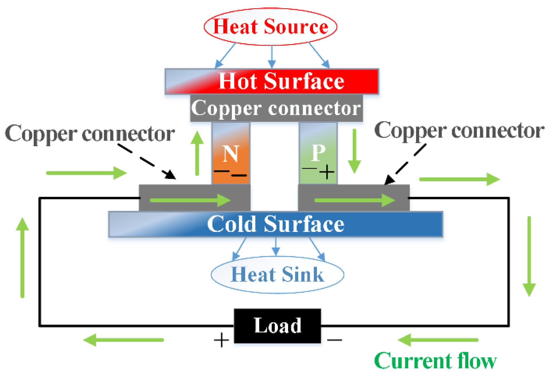
Figure 2.
The electrical equivalent circuit model of the TEG.
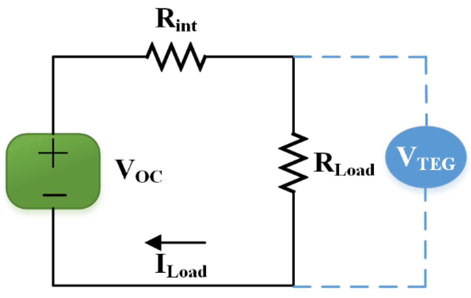
Figure 3.
Power and efficiency characteristics of the designed TEG module.
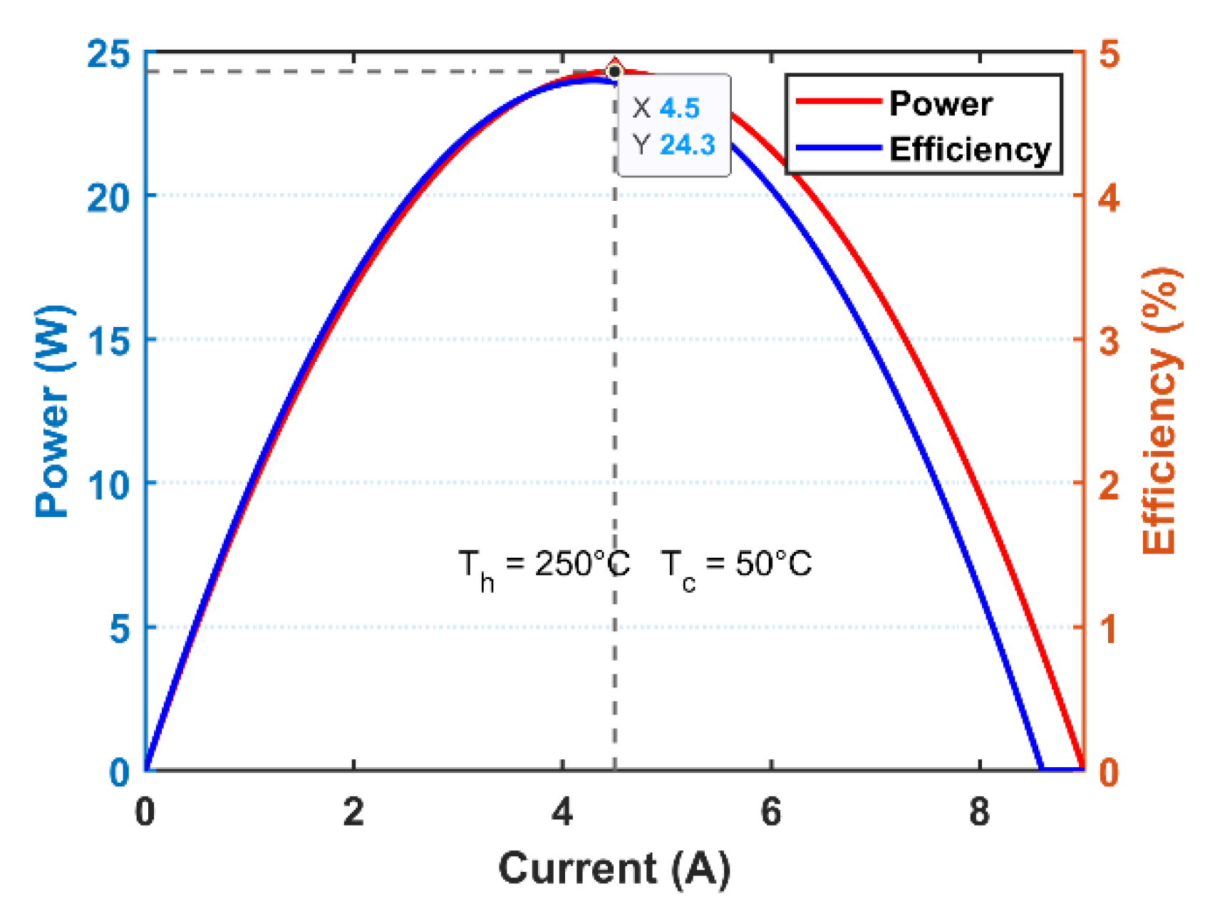
Figure 4.
I-V and P-V curve of the designed TEG module.
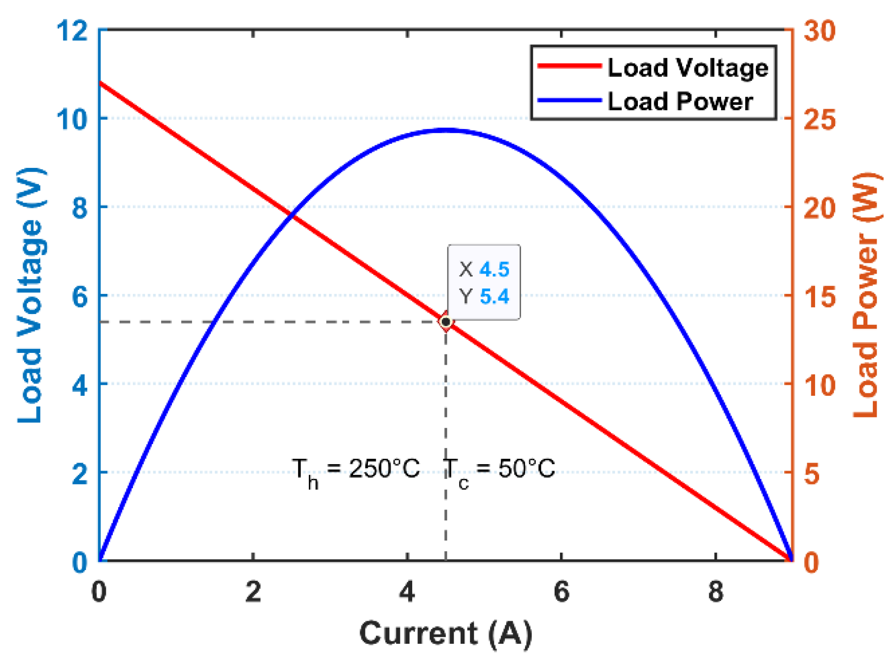
Figure 5.
The proposed TEG-supplied system.
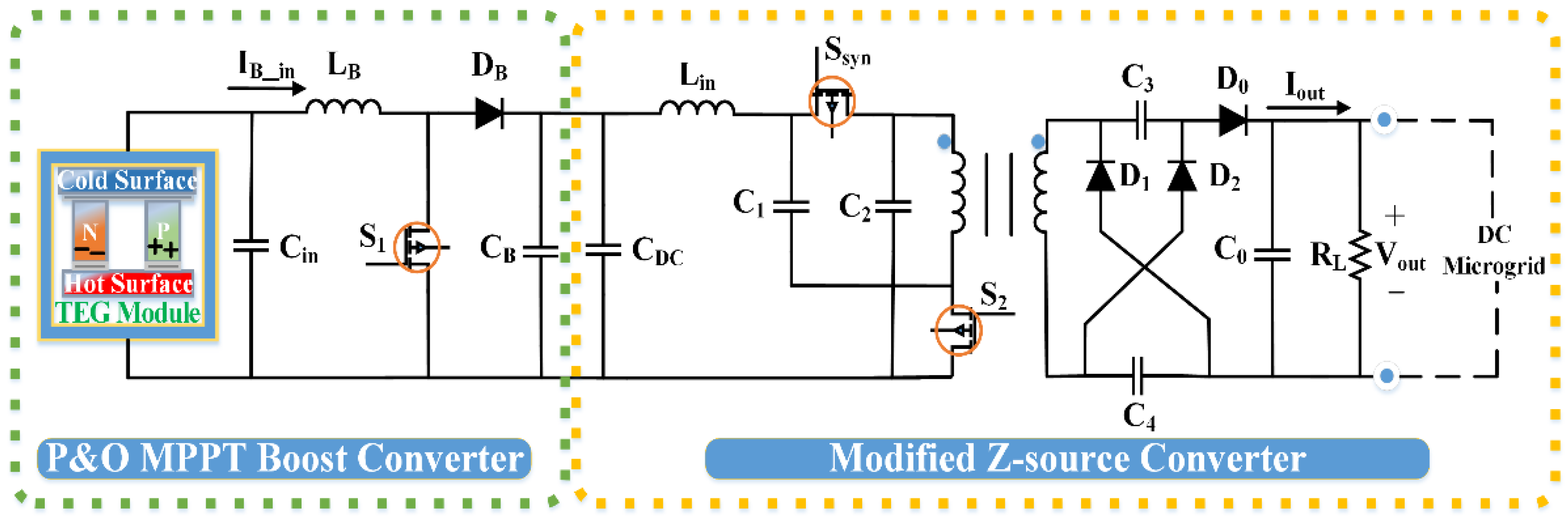
Figure 6.
Flowchart of the duty-cycle-based Perturb and Observe (P&O) MPPT algorithm.

Figure 7.
Block diagram of the conventional SMC method.
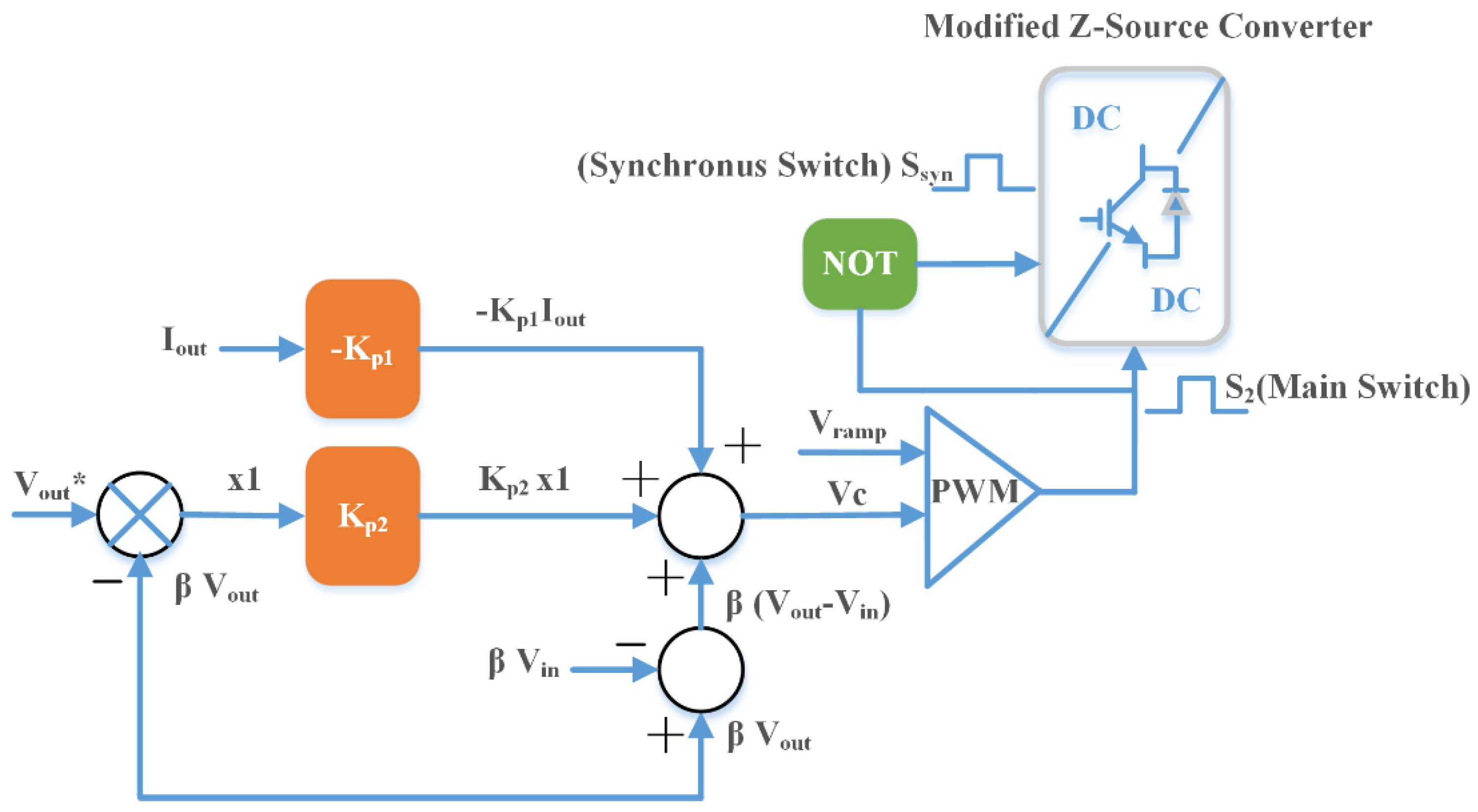
Figure 8.
Block diagram of the conventional MPC method.
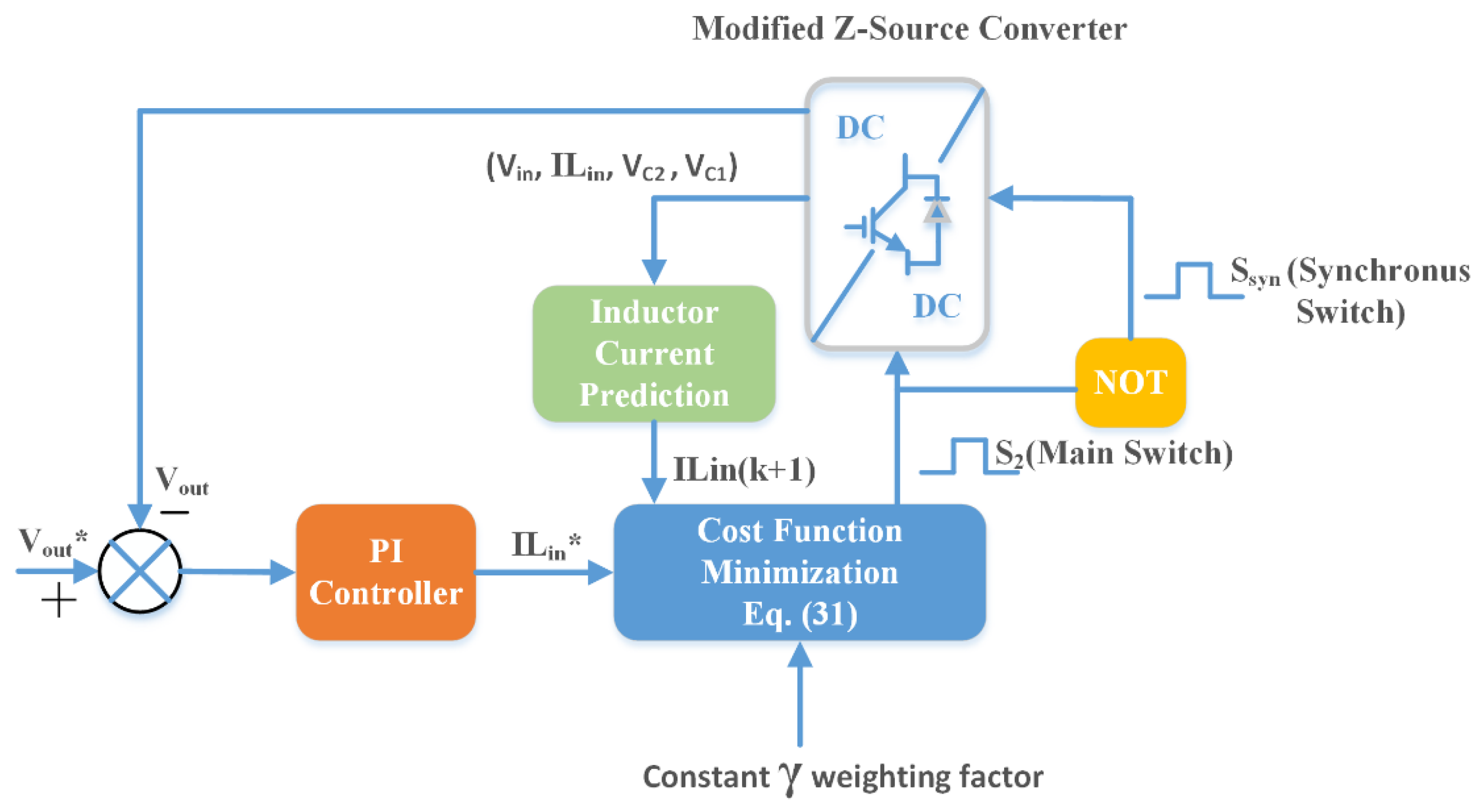
Figure 9.
Block diagram of the advanced MPC method.
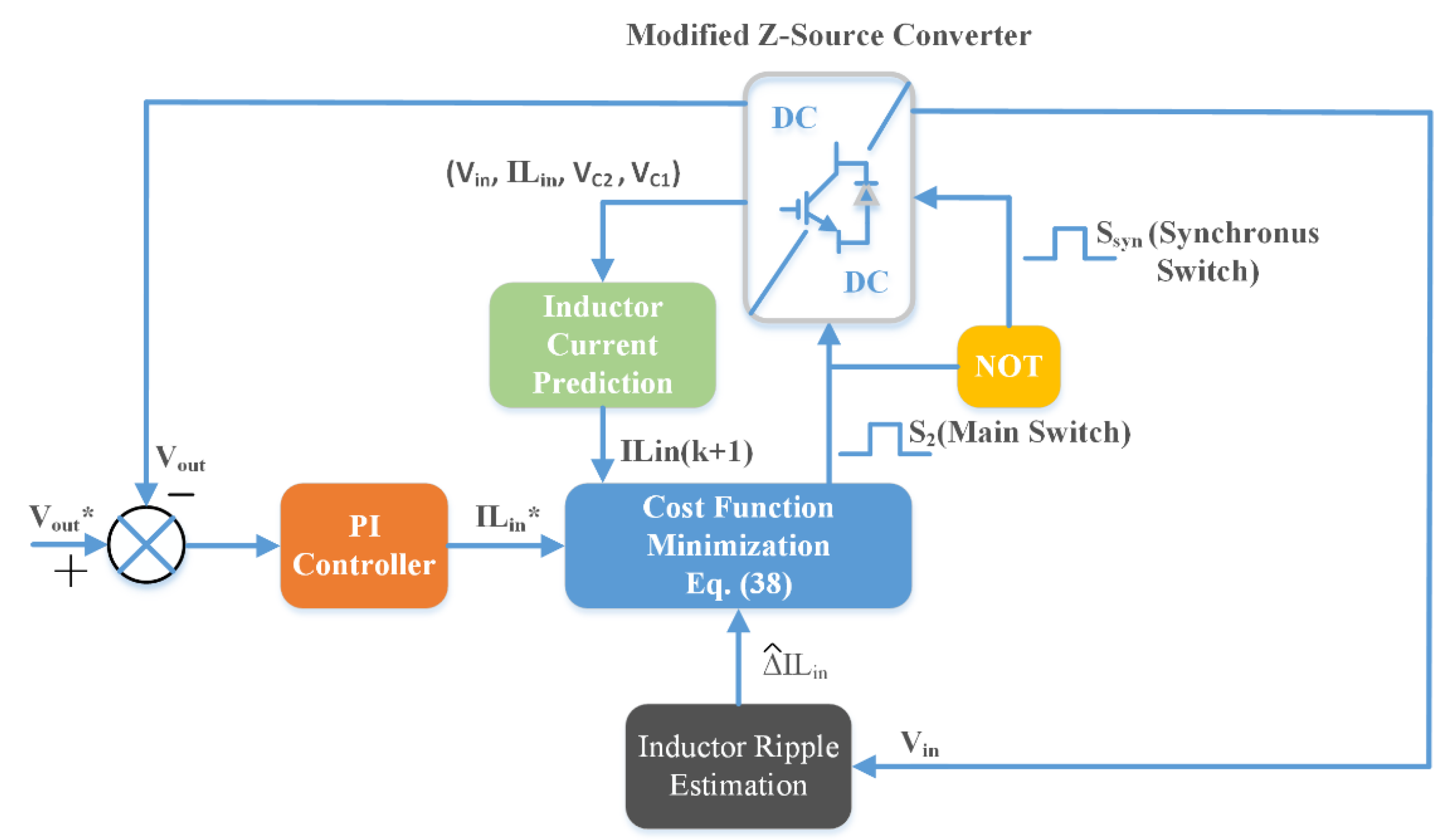
Figure 10.
The proposed boost converter under hot side temperature variations: (a) Input voltage and current; (b) output voltage and current.
Figure 10.
The proposed boost converter under hot side temperature variations: (a) Input voltage and current; (b) output voltage and current.
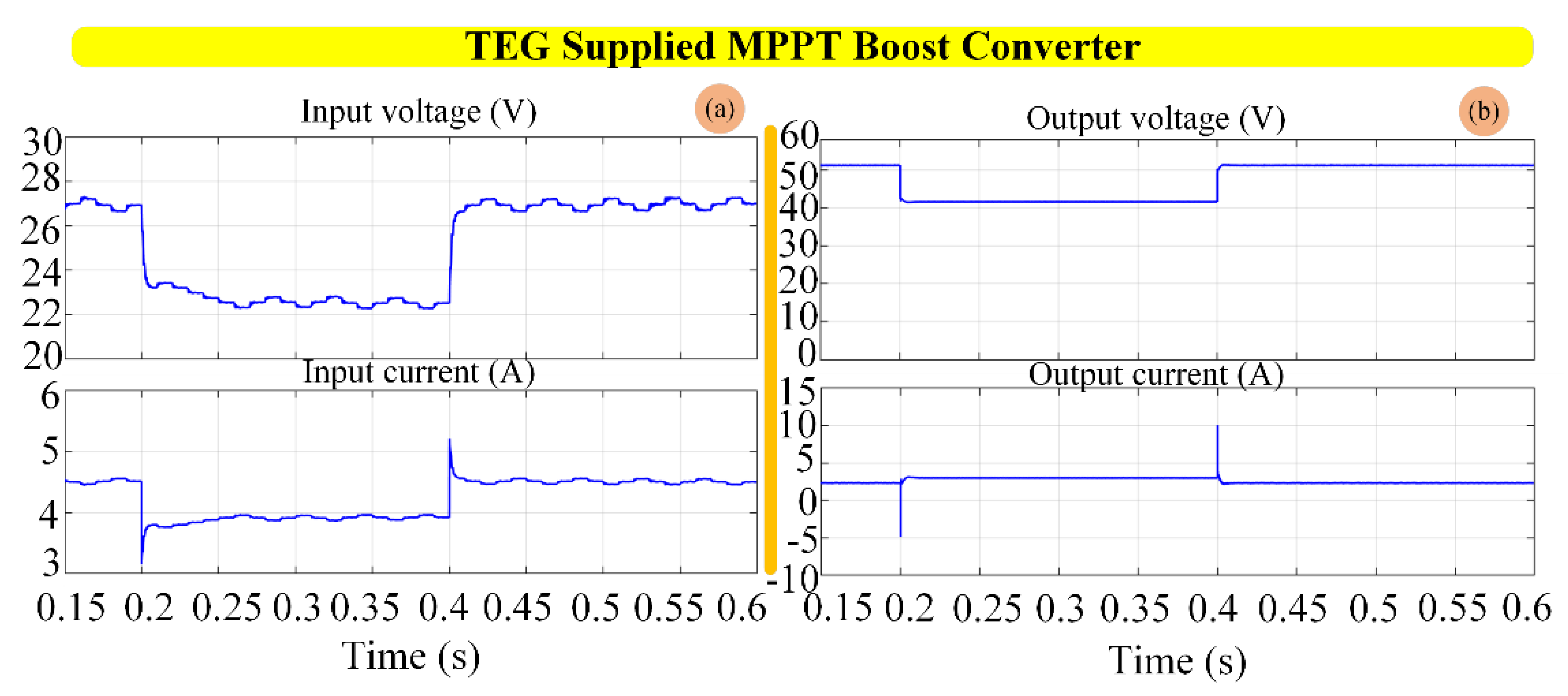
Figure 11.
Dynamic response of the proposed system using conventional SMC under hot side temperature variations.
Figure 11.
Dynamic response of the proposed system using conventional SMC under hot side temperature variations.
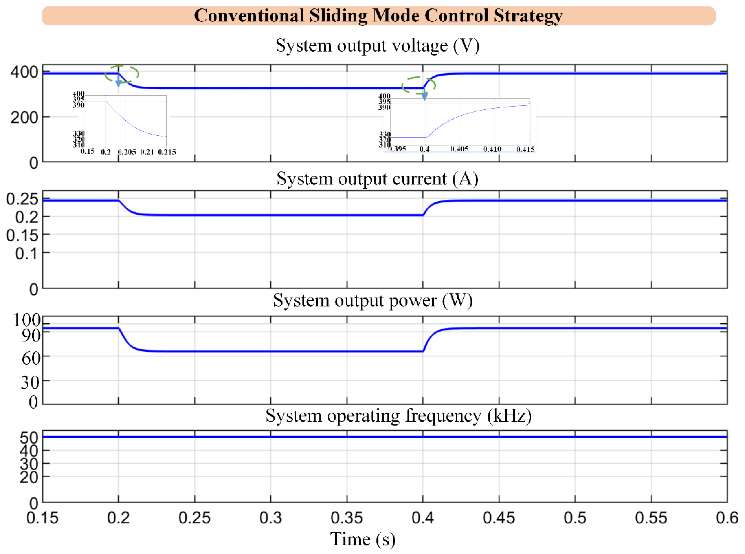
Figure 12.
Dynamic response of the proposed system using conventional MPC under hot side temperature variations.
Figure 12.
Dynamic response of the proposed system using conventional MPC under hot side temperature variations.
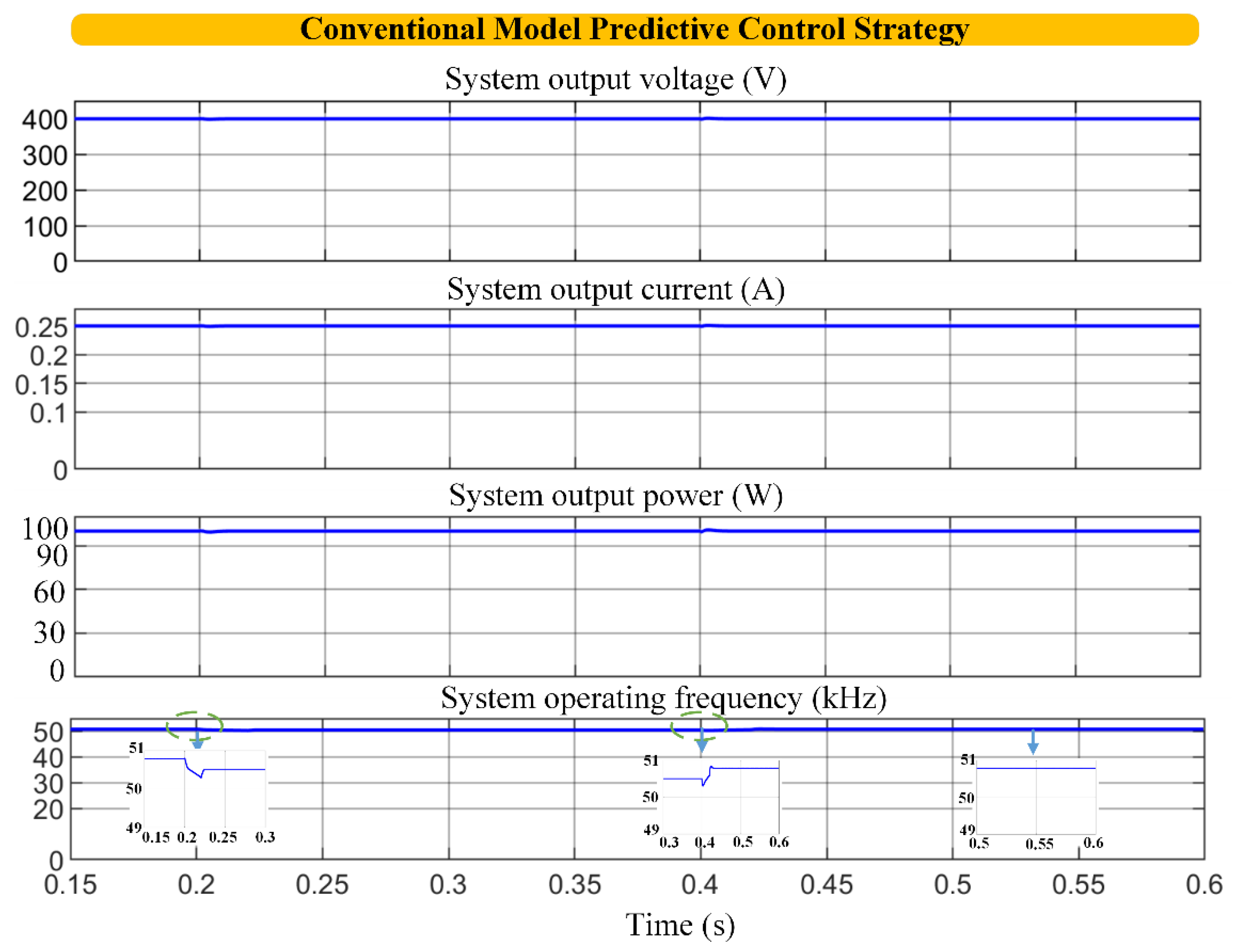
Figure 13.
Dynamic response of the proposed system using advanced MPC under hot side temperature variations.
Figure 13.
Dynamic response of the proposed system using advanced MPC under hot side temperature variations.
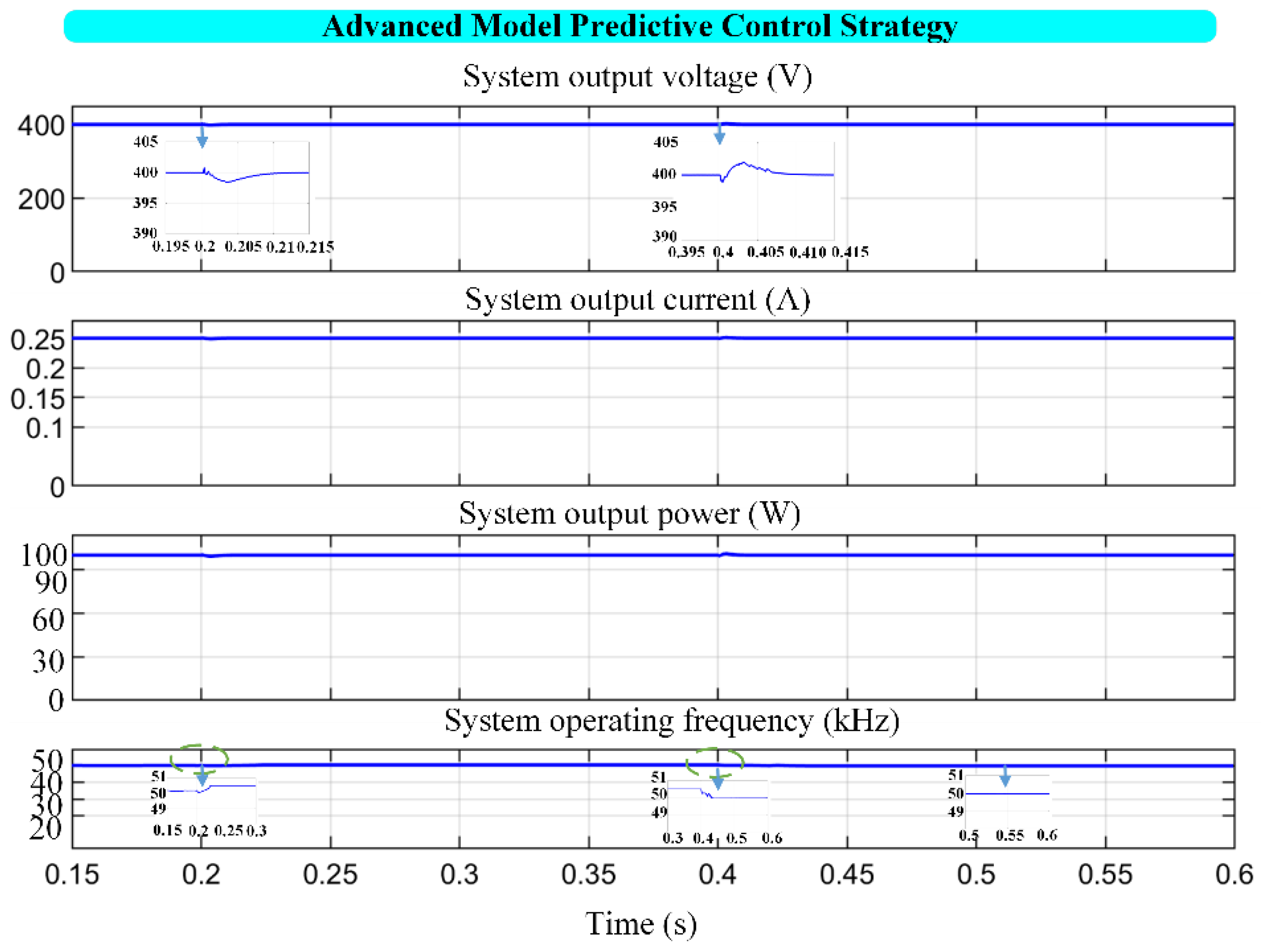
Figure 14.
Dynamic response of the proposed system using advanced MPC under load test scenarios.
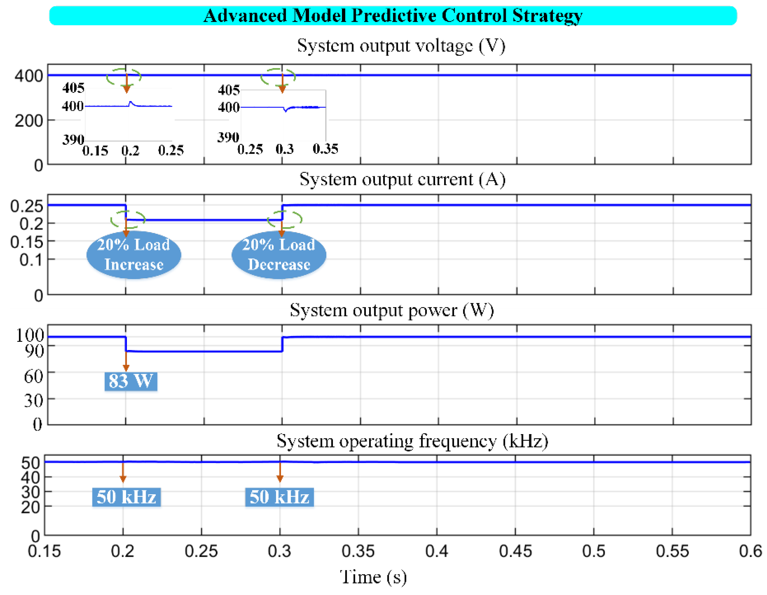

Table 1.
Parameter specifications of the proposed system.
| Component | Parameter | Value | Symbol |
|---|---|---|---|
| TEG unit | Thermoelectric modules | 5 | - |
| Output power at MPP | 121.5 W | ||
| Output voltage at MPP | 27 V | ||
| Output current at MPP | 4.5 A | ||
| Open circuit voltage | 54 V | ||
| Short circuit current | 9 A | ||
| Internal resistance | 6 Ω | ||
| Seebeck coefficent | 0.054 V/K | ||
| Hot surface temperature | 250 °C | ||
| Cold surface temperature | 50 °C | ||
| Output voltage | 51.1 V | ||
| Output current | 2.33 A | ||
| Input capacitor | 250 µF | ||
| Filter Inductor | 300 µH | ||
| Boost converter | Filter capacitor | 50 µF | |
| DC link capacitor | 2.5 mF | ||
| Switching frequency | 50 kHz | ||
| Modified Z-source converter | Output voltage | 400 V | |
| Output current | 0.25 A | ||
| Output power | 100 W | ||
| Input inductor | 120 µH | ||
| Capacitor | 100 µF | ||
| Capacitor | 100 µF | ||
| Capacitor | 1 µF | ||
| Capacitor | 1 µF | ||
| Capacitor | 33 µF | ||
| Load | 1600 ohm | ||
| Turn ratio | 4 | n |
Table 2.
The proposed modified Z-source converter specifications.
| Definition | Calculated | Measured |
|---|---|---|
| Capacitor voltage, | 17.03 V | 19.02 V |
| Capacitor voltage, | 68.13 V | 68.45 V |
| Capacitor voltage, | 66.64 V | 64.50 V |
| Capacitor voltage, | 66.64 V | 64.50 V |
| Capacitor voltage, | 400.13V | 400 V |
| Diode voltage, | 340.67 V | 333 V |
| Diode voltage, | 340.67 V | 333 V |
| Diode voltage, | 340.67 V | 333 V |
Table 3.
Comparison of proposed system with existing prominent systems in the literature.
| Description | [16] | [34] | [23] | Proposed |
|---|---|---|---|---|
| Converter type | Multilevel Modular | Flyback | Boost | Modified Z- source |
| Control strategy | Resonant control | Open loop | Fast Terminal SMC | Advanced MPC |
| Dynamic response | No | No | Yes | Yes |
| Isolation between sides | No | Yes | No | Yes |
| Output power Operating frequency |
630-W 70 kHz |
19-W 100 kHz |
5-W - |
100-W 50 kHz |
| Voltage gain | High | Low | Low | High |
Disclaimer/Publisher’s Note: The statements, opinions and data contained in all publications are solely those of the individual author(s) and contributor(s) and not of MDPI and/or the editor(s). MDPI and/or the editor(s) disclaim responsibility for any injury to people or property resulting from any ideas, methods, instructions or products referred to in the content. |
© 2026 by the authors. Licensee MDPI, Basel, Switzerland. This article is an open access article distributed under the terms and conditions of the Creative Commons Attribution (CC BY) license (http://creativecommons.org/licenses/by/4.0/).
Copyright: This open access article is published under a Creative Commons CC BY 4.0 license, which permit the free download, distribution, and reuse, provided that the author and preprint are cited in any reuse.


