Submitted:
11 February 2026
Posted:
12 February 2026
You are already at the latest version
Abstract
This research proposes a robust multi-objective NSGA-II heuristic optimization framework for CFRP (Carbon Fiber Reinforced Polymer) wrapping to promote seismic-resilient and low-carbon high-rise infrastructure. The method integrates nonlinear time-history analysis with a multi-objective genetic algorithm to determine optimal CFRP application conditions, including whether floors require CFRP wrapping, mortar jacketing, steel jacketing, or combinations thereof. It further optimizes CFRP thickness, orientation, design pattern (unilinear, bidirectional, hybrid), coverage, and anchorage details. Optimization simultaneously minimizes overall cost, torsional irregularity index, Park–Ang damage index, and seismic sensitivity while maintaining structural reliability under seismic loading. Simulation results indicate that proposed CFRP framework reduces torsional impacts by approximately 35%, enhancing seismic resilience. Hybrid CFRP configurations combined with 20–40 MPa mortar and optional 10–40 mm steel jacketing showed improved structural performance. Anchorage of 0–2 per end per face reduced torsional drift to ≤0.5–1.0%. For a 10-storey building, lower floors benefit from CFRP with mortar/steel jacketing up to ±45°, mid-level floors from hybrid (0/±45°) configurations, and upper floors from predominantly ±45° CFRP with occasional 90° bands. CFRP thickness of 0–3 mm (0–6 plies) achieved improved seismic resilience, cost efficiency, and structural reliability, supporting its potential for seismic-resilient infrastructure policy and design.
Keywords:
CFRP
; multi-story building design
; seismic resilience
; cost-efficient construction
; reliability
1. Introduction
Despite significant advances in engineering and technology, earthquakes remain amongst the most destructive natural hazards, with their occurrence, location, and magnitude still largely unpredictable [1]. A key contributor to earthquake-caused casualties is the intrinsic vulnerability of building structures [1,2]. Hence, examining the seismic performance of both newly constructed as well as existing buildings, especially multi-storey building has emerged as a vital concern for researchers and (industrial) practitioners in the construction sector [3]. Reinforced concrete (RC) structures, which form a decisive part of global urban infrastructure, are primarily vulnerable to earthquake’s damage(s) [3,4]. Their performance under seismic loading can be examined by means of the different numerical assessment methods, which are now standard practice in structural engineering [4]. The literatures indicate that inadequate seismic performance is a predominant reason behind human and economic loss(es) during earthquakes [2,3,4]. The extent of structural damage is mainly controlled by amalgamating multiple factors, encompassing earthquake intensity, local soil conditions, and the quality of design and construction [5,6]. In major urban regions, aging RC buildings with the confined seismic capacity show different extent of vulnerability under strong ground motions [6]. Pre-disaster performance assessment of high-rise structures is therefore inevitable to mitigate both life as well as property losses [4]. Structural analysis serves a key tool for stakeholders, enabling informed decisions on whether to retrofit or replace deficient buildings [4]. Strengthening interventions can enhance seismic resilience of existing RC structures decisively, permitting their efficacy to align more closely with modern-day safety standards [7]. Traditional RC buildings often show seismic limitations because of the inadequate realization of earthquake-resistant design paradigms during their original construction that decisively heightens their risk over seismic events. As a proactive mitigation plan, seismic assessment coupled with cost-effective retrofitting has been extensively recognized as a vital and effective techniques for reducing earthquake-related losses [8]. Yet, retrofit solutions must be both technically possible and economically sustainable [4]. Common weaknesses encompass insufficient shear strength in columns and joints, structural irregularities, and non-ductile detailing [5,6,7]. Identifying these limitations at both local as well as global levels is vital to devise effective retrofitting strategy. While linear static and dynamic assessments are usually applied for seismic assessment, they typically fail to retrieve the challenges of nonlinear seismic demands [4,6]. This as a result yields more advanced assessment techniques and adaptive retrofitting are needed particularly for vertical load-bearing elements to guarantee reliable performance under nonlinear seismic loading [9].
The introduction of advanced seismic design codes across Europe during the 1980s decisively enhanced the earthquake resilience of newly constructed vertical structures or buildings [9]. Yet, a large fraction of the existing building predates these regulations and, consequently, remains vulnerable when subjected to nonlinear seismic conditions [10]. Retrofitting these types of structures not only improves safety but also increases service life, thus enables long-term economic benefits [11,12,13,14]. When seismic improvements are amalgamated with energy-efficiency enhancements, the overall cost-efficacy of retrofitting increases, which might later increase its adoption in practice [15,16]. Amongst the at-hand methods, externally bonded fiber-reinforced polymer (FRP) composites can be of paramount significance due to their high tensile strength, corrosion resistance, and ease of application [12,13,14,15]. In the last few decades, extensive researches have been done towards FRP-based retrofitting, paving the way for the development of practical design codes and field implementation guidelines. FRP composites are predominantly employed to enhance the load-bearing capacity and ductility of RC members by means of a number of retrofitting mechanisms [9,10,11]. Mainly, the flexural strengthening is extensively adopted to increase load capacity as well as to relocate plastic hinges away from beam-column joints. This shift assists transform the failure process from a more critical column-sway mode to a more expected beam-sway mode [9,10,11]. A frequently used method for flexural enhancement is the flange-bonded FRP system, which can be installed in critical beam and column regions without causing critical interference and/or alterations with the slab system. Yet, the efficacy of externally bonded FRP systems can be compromised by premature debonding, which remains a decisive limitation. To address such challenge, numerous innovative anchorage methods have been proposed and validated in the past, showing enhanced reliability and efficacy to prevent debonding failures [9,12,13,14,15].
Traditional seismic retrofitting techniques for RC structures typically depend on the methods like RC or steel jacketing and the addition of new shear walls [17]. Recently, yet, FRP systems have gained significant attention as an alternative because of their functional advantages over concrete- and steel-based solutions. FRP retrofitting enables faster installation, minimized disruption to the occupants, and reduced downtime for residential and commercial multi-story buildings, which cumulatively lower retrofitting costs [18,19]. Beyond these realistic advantages, FRP composites perform superior material characteristics like a high strength-to-weight ratio, minute added thickness, and strong resistance to corrosion, thus making them more durable in long-term strengthening applications [20,21]. Practically, FRP retrofitting is frequently employed at the local element level, where the emphasis is made on reducing deficiencies that compromise seismic resilience or performance. For instance, column wrapping is extensively employed to improve confinement, increase shear capacity, and improve chord rotation [22,23,24,25]. In the same manner, shear-deficient beam–column joints are usually strengthened by applying FRP to preserve structural integrity under seismic loading [26,27]. Practical design specification for such localized retrofitting mechanism(s) has been discussed in numerous literatures including Pantazopoulou et al. [28] that serve engineers with structured approaches for implementation.
While local improvement (say, retrofitting tasks) with FRP has been extensively studied in the past and has now become the key part of mainstream engineering practices [16], research on global seismic retrofitting with FRP remains relatively confined [23,24,25]. Global methods on the other hand focus on performing system-level enhancement in structural hierarchy, targeting to improve overall ductility and load-carrying capacity. Examples embody intentional slab weakening, column flexural strengthening with FRP strands, beam strengthening in both shear and flexure, and joint shear enhancement through FRP applications [17,18,19,20,21]. In one innovative configuration, FRP strands were left unbonded at the column base and threaded through a plastic tube so as to interface with the lower-story columns, thus dropping the demand of direct anchorage in concrete [29]. Full-scale subassembly analyses show that the above discussed retrofitting mechanism not only increases load capacity but also improves ductile beam-sway mechanism. More importantly, this method shows that the damage can be reduced and constrained within a specific plastic hinge regions in the beams, thus protects joint panels and columns and preserving vertical load-resisting capacity.
The depth assessment of the state-of-art solutions also infer that the classical seismic retrofitting of RC structures primarily relies on the techniques like steel or RC jacketing and the addition of new shear walls [17]. However, the efficacy of FRP systems enables it as a viable and more potential alternate which has attracted growing interest. This is mainly because of their operational significances. In comparison to the concrete- or steel-based approaches, FRP retrofitting enables quicker installation, while ensuring minimal disruption to occupants, and shorter downtime in residential and commercial facilities. It also minimizes overall retrofitting costs [18,19]. Additionally, FRP composites possess promising mechanical characteristics including a high strength-to-weight ratio, negligible added thickness, and excellent resistance to corrosion, making them suitable towards durable, long-term retrofitting purposes [20,21]. Practically, FRP retrofitting is primarily employed at the local element scale, emphasizing limitations embodying seismic performance. Usually, applications embody column wrapping to improve confinement, shear strength, and chord rotation capacity [22,23,24,25]. FRP is also primarily employed to improve shear-deficient beam–column joints, which are vital to maintain structural integrity under seismic loading conditions [26,27]. Practical design specifications or guidance for these localized techniques has been consolidated by Pantazopoulou et al. [28], thus helping engineers with the structured mechanisms for applications. While localized FRP retrofitting technique is well established in both research and real-time applications [16], researches on global seismic retrofitting by applying FRP remain relatively confined [23,24,25]. Global methods target to improve overall system characteristics by improving ductility and load-carrying capacity throughput the vertical structure. Representative techniques encompass slab weakening, beam strengthening in shear and flexure, joint shear enhancement with FRP, and column flexural strengthening by applying FRP strands. In one innovative retrofitting mechanism, FRP strands were left unbonded at the column base and guided by means of a plastic tube to connect with lower-story columns, thus avoiding direct anchorage into concrete [29]. Full-scale beam–column subassembly tests revealed that this technique not only improved load capacity but also improved a ductile beam-sway technique. Primarily, the damage was confined to designated plastic hinge regions in beams, thereby protecting joint panels and columns while preserving vertical load-carrying capacity.
Shear–torsional interactions play a decisive role in the seismic response of multistory buildings, especially those with non-linear and complex geometry, mass distribution, or stiffness variation [102]. Shear effects, arising from lateral forces induced by ground motion, subject the structure to increased internal forces and displacements [102]. In the same manner, torsional effects take place when a building undergoes twisting about its vertical axis, typically due to the eccentricity between the center of mass (CM) and the center of rigidity (CR). These coupled actions amplify lateral displacements and rotations, leading to non-uniform inter-story drifts and higher stresses in vertical load-resisting elements [103]. Previous studies have emphasized that torsional irregularities tend to concentrate deformations in weaker stories (say, ground-level soft stories), thus heightening the risk of severe damage or even collapse during strong earthquakes [102,103]. Amplified torsional demands can intensify vibrations in non-linear multi-storey buildings, further exacerbating seismic responses. This non-linear distribution of seismic demand might result in localized failures, eventually compromising global structural stability. Despite the witnessed impact of shear–torsional effects, existing CFRP-based retrofitting solutions for RC buildings merely account for these dynamics during design optimization. Addressing this gap is inevitable, as optimizing CFRP retrofits with consideration of shear–torsional behavior could decisively enhance overall stability and seismic resilience. Emerging techniques, encompassing machine learning and artificial intelligence, present promising opportunities to retrieve complex load–response interactions by integrating seismic demand patterns with structural characteristics. Leveraging such approaches may enable the development of CFRP retrofit strategies that enhance global stability and safety in multistory RC buildings. This forms a central motivation for the present research.
This paper contributes an MOGA heuristic optimization driven CFRP wrapping solution (say, framework) for the multi-storey building. Particularly, the proposed method applies non-linear time-history analysis with MOGA heuristic algorithm to decide whether a specific floor in a multi-storey building (here, 10 storey building) needs CFRP wrapping, mortar and steel jacketing. The proposed MOGA method subsequently decides CFRP wrapping conditions on each floor including thickness, orientation, design patterns (i.e., unilinear, bidirectional and hybrid), coverage and anchors etc. It achieves above stated objectives while minimizing the CFRP costs (i.e., CFRP, resin, steel and mortar), torsional irregularity index (i.e., per floor drift and torsional surrogate), Park Ang damage index and sensitivity towards seismic resilient multi-storey building development. The CFRP wrapping is performed while constraining non-structural elements that improves reliability of the targeted multi-storey building (under seismic loading conditions). MATLAB simulations and allied inferences reveal that the proposed CFRP wrapping structure can reduce torsional impacts by 35%. The depth performance characterization reveals that the hybrid CFRP structure with 20-40 MPa mortar embodying steel jacketing of 10-40 mm (if used) can make CFRP structure more seismic-resilient. It suggests to implement 0-2 per end per face anchorage to reduce torsional impacts and residual drift (≤ 0.5–1.0%). For a 10-storey building, the simulations revealed that for the lower floor including 1-3 floors, if the damage index remains same the mortar and steel jacketing can be applied with the CFRP orientation up to ±45°. For 4-7 floors, hybrid 0/±45° CFRP can be applied which can balance drift as well as torsional instability under seismic loading condition. Though, for 8–10 stories, ±45° dominant CFRP can be suitable with the occasional 90° bands near joints to maintain stability and low sensitivity. For the targeted 10-floor building structure, CFRP thickness can be selected in the range of 0-3 mm, where it can apply 0.-6 plies of ~0.17–0.5 mm/ply. The design outputs and allied mechanical characterizations confirm robustness and seismic resilience of the target structure, which can make constructions more reliable and cost-effective.
The other sections of the manuscript are given as follows. Section II presents the related work, which is followed by research questions in Section III. The overall proposed methods and corresponding simulation results are given in the Section IV and Section IV, respectively. Section V presents the conclusion, which is followed by references at the end of the manuscript.
2. Related Work
Fiber-reinforced polymer (FRP) composites have gained wide acceptance as an effective means of enhancing the seismic performance of reinforced concrete (RC) structures, owing to their favorable characteristics such as low weight, high tensile capacity, corrosion resistance, and ease of installation [36,37,38]. In contrast to traditional strengthening techniques, FRP-based retrofitting offers a cost-efficient and non-intrusive solution, particularly advantageous in sites with spatial limitations [39,40]. Reflecting this efficiency, several international codes and guidelines now endorse the application of FRP systems for the rehabilitation of RC components. Among the notable contributions to this area is the FEMA P-695 [41], which consolidates recent advancements in earthquake engineering across the United States. The report incorporates comprehensive ground motion records, refined attenuation models, probabilistic seismic hazard methodologies, advanced nonlinear analysis strategies, and computational frameworks for collapse simulation. Furthermore, it proposes a probabilistic evaluation procedure to verify whether existing buildings can reliably meet collapse-prevention performance objectives under seismic excitation.
Recent investigations into the seismic retrofitting of RC members with FRPs have predominantly employed pseudo-static loading tests on beams and columns. Katsumata et al. [42] examined the effect of FRP confinement on RC columns through low-cycle hysteresis experiments conducted on fifteen 1:4 scaled specimens, reporting improved seismic performance after strengthening. In a similar vein, Saadatmanesh et al. [43] applied glass FRP (GFRP) jackets to five circular columns at a 1:5 scale, and their results highlighted substantial gains in lateral resistance due to confinement. Ye et al. [44] retrofitted eight square columns with CFRP sheets and observed marked enhancements in both ductility and load-carrying capacity, thereby confirming CFRP’s efficacy. Richelle and Kawashima [45] not only tested six CFRP-jacketed circular columns but also developed an analytical model to reproduce their hysteretic response, subsequently extending the methodology to a prototype bridge pier, which underscores the scalability of FRP-based solutions. The mechanical response of FRP-strengthened joints, however, remains more complex. Ghobarah and Said [46] investigated T-shaped beam–column joints reinforced with GFRP and demonstrated significant increases in shear strength and deformation capacity compared with unstrengthened specimens, while also mitigating brittle shear failure. Expanding beyond passive retrofitting, Wang et al. [47,48] introduced a semi-active tuned mass damper system with variable stiffness and damping, verifying its efficiency through laboratory testing. Antonopoulos et al. [49] performed one of the most comprehensive studies to date, analyzing eighteen 2:3 scaled T-shaped beam-column joints strengthened with either CFRP or GFRP. Their work systematically assessed the influence of key parameters, including axial load ratio, joint reinforcement ratio, bonding configuration, beam stirrup arrangement, and initial damage state on seismic performance, thereby demonstrating the multifaceted role of FRP in enhancing structural resilience. Beyond the strengthening of individual members and joints, considerable research has examined the seismic performance of entire FRP-retrofitted frames. Duong et al. [50] studied low-ductility RC frames enhanced with CFRP and reported significant improvements in load-bearing capacity, ductility, and energy dissipation. El-Sokkary and Galal [51] employed finite element simulations to assess retrofitting schemes for deficient RC frames, concluding that FRP confinement of beams and columns can markedly improve global seismic resistance. Along similar lines, Shaikh et al. [52] investigated frames retrofitted by wrapping critical fracture zones of beams and columns with CFRP, and their results highlighted improvements in both global response and local performance indicators. Ali et al. [53] further demonstrated that a combination of FRP flexural strengthening and confinement leads to substantial gains in the overall reliability of RC frames.
More recently, advanced computational studies have provided deeper insight into FRP-retrofitted systems. Rousakis et al. [54,55], Fanaradelli et al. [56,57,58], and Anagnostou et al. [59] collectively showed that hybrid methodologies; integrating three-dimensional nonlinear finite element models with analytical frameworks such as the Modified Compression Field Theory (MCFT) can enhance predictive accuracy for seismic response and assist in refining design guidelines. The strengthening of RC frames with CFRP has been extensively validated over the past decades; however, most studies have concentrated on undamaged structures, while relatively fewer efforts have addressed the retrofitting of earthquake-damaged frames. Post-seismic rehabilitation is often urgent, as severely affected RC frames must be restored to serviceability [60,61,62,63,64,65,66,67]. Despite this pressing need, investigations into the seismic performance of damaged frames retrofitted with CFRP remain limited, offering only partial guidance for effective reconstruction strategies. To bridge this gap, Eslami and Ronagh [68] experimentally evaluated both damaged and undamaged RC beam–column subassemblies retrofitted with flange-bonded FRP composites. Their results revealed that, when combined with a grooved anchorage system, the technique substantially increased joint flexural strength and successfully shifted plastic hinge formation away from the critical column–beam interface. Retrofitted specimens exhibited a 30% improvement in ultimate load capacity compared to pre-cracked controls, although this came at the expense of reduced displacement ductility due to the higher reinforcement ratio introduced by the external FRP. Extending this work, Ronagh and Eslami [69] applied flange-bonded FRP to an eight-story RC frame and, through nonlinear pushover analysis, reported increases in lateral strength of 43% for GFRP and 80% for CFRP. While CFRP achieved greater lateral capacity gains, it was accompanied by lower ductility. In a subsequent study, Eslami et al. [70] performed nonlinear time-history analysis on the same structure, showing that CFRP retrofitting reduced maximum inter-story drift under near-fault motions from 3.3% to 2.4%.
Beyond flexural retrofitting, FRP wraps have proven effective in confining critical regions prone to plastic deformations. Di Ludovico et al. [71] retrofitted a three-story RC building using wrapped and web-bonded GFRP composites, and pseudo-dynamic tests demonstrated that the retrofitted system withstood approximately 50% higher peak ground acceleration compared with the original structure. The intervention also yielded substantial improvements in ductility and energy dissipation, consistent with findings from other experimental studies [72,73,74]. Nevertheless, these works primarily adopted deterministic assessment methods, without explicitly accounting for uncertainties in seismic demand, material variability, or geometric irregularities. To address this limitation, recent studies have explored reliability-based approaches at the component scale, particularly for FRP-strengthened RC beams [75,76,77,78] and columns [79,80,81]. However, comprehensive system-level reliability assessments of FRP-retrofitted RC frames remain scarce, leaving a critical gap in performance-based seismic design and evaluation.
To enhance the seismic reliability of RC structures, Zou et al. [82] developed an optimization framework based on reliability theory to determine the optimal level of FRP confinement. Their method primarily accounted for earthquake-induced uncertainties while intentionally neglecting variations in material and structural properties to maintain computational efficiency. Extending this line of research, Ali et al. [83] applied a reliability-based approach to assess two retrofit schemes for a three-story RC frame: (i) column confinement with FRP, and (ii) a combined strategy involving flexural strengthening of beams and columns in addition to column confinement. Using fragility curves derived from maximum roof drift, they demonstrated that the combined retrofit improved structural reliability by 32%, compared with only 16% from confinement alone. Although these findings confirmed the potential of reliability-based frameworks for retrofit evaluation, the study did not explicitly quantify collapse capacity, underscoring the need for probabilistic approaches that can better capture structural failure risks and facilitate comparison of retrofit alternatives. Experimental evidence further supports the efficiency of advanced retrofit strategies. Hou et al. [84] reported that CFRP wraps successfully rehabilitated RC columns with partially deteriorated concrete, providing substantial confinement. Other techniques have also been explored, such as steel jacketing and numerical modeling, as highlighted by Garcia [85]. Mohammed [86] investigated shear-critical RC beams strengthened with ultra-high-performance fiber-reinforced concrete (UHPFRC) panels and observed a shift in failure mechanism from brittle shear to ductile flexural behavior, along with enhanced shear strength. Similarly, Meraji et al. [87] studied UHPFRC overlays applied to RC beams and reported significant gains in flexural strength and energy dissipation.
Building on these prior developments, the present study introduces a new seismic evaluation framework that integrates the “Material Strain Limit Approach” with the “Quadrants Assessment Method.” Two RC building models were considered: a 30-year-old single-story structure located in the Koyna–Warna region, characterized through in-situ measurements, and a newly designed building conforming to current seismic codes. Following seismic assessments of both cases, tailored retrofitting strategies were implemented, and the outcomes systematically compared to assess their effectiveness. Retrofit strategies generally combine local and global interventions to improve the seismic performance of RC structures [88,89]. Günay and Sucuoğlu [89] demonstrated that nonlinear static analysis can provide performance evaluations comparable to nonlinear dynamic analysis for deficient buildings, thereby offering a computationally efficient alternative. Structural irregularities such as soft stories, torsional imbalances, and short-column effects are known to exacerbate seismic vulnerability, as highlighted by Fajfar [90]. To further reduce the computational burden of seismic assessment, Vielma et al. [91] introduced the Quadrants method, which significantly accelerates analysis while retaining accuracy and reliability. Given the heightened seismic risks in earthquake-prone regions, the retrofit of older, non-engineered RC buildings has become a critical priority. Mohamed et al. [92] proposed a comprehensive retrofitting scheme for deteriorated buildings that involves installing new grid beams and replacing the existing basement slab, thereby improving overall load transfer and lateral resistance. Alternative reinforcement strategies have also been investigated. For example, Lee et al. [93] studied RC columns reinforced with screw-ribbed bars and mechanical splices, reporting improved seismic performance. Jafarzadeh and Nematzadeh [94] examined GFRP-reinforced concrete beams subjected to post-fire retrofitting using CFRP sheets. Testing ten beams under varied parameters—including exposure temperatures between 20 °C and 600 °C, steel fiber dosage, rebar ratios, and CFRP layers—they observed that CFRP retrofitting significantly restored and enhanced flexural performance even at elevated temperatures. Steel fibers contributed to crack control and altered failure modes, while higher rebar ratios increased load capacity only in beams not exposed to fire. The experimental results closely matched predictive models, confirming the reliability of CFRP strengthening for fire-damaged beams.
Comparative evaluations of strengthening techniques have also been performed. Mumtaz et al. [95] investigated FRP wrapping versus RC jacketing for retrofitting columns in Afghanistan. Their findings indicated that RC jacketing provides a more favorable strength-to-cost ratio for severely damaged or weak columns, whereas FRP wrapping offers advantages in terms of faster application and environmental sustainability. Cosgun et al. [96] evaluated RC buildings retrofitted with newly added shear walls using finite element modeling. Their results confirmed that shear walls significantly improved lateral stiffness and reduced displacements; however, they cautioned that misalignment between mass and stiffness centers could increase shear demand, which must be accounted for in retrofit design. A case study reported by John Wiley & Sons Ltd [97] examined the rehabilitation of a small earthquake-damaged two-story structure, where ground-floor columns were identified as critical weaknesses. Due to site and design constraints, shotcrete jacketing was selected as the only practical intervention. Other researchers have focused on FRP-based methods. Arslan et al. [98] investigated different CFRP retrofitting schemes for T-beams and demonstrated that both full wrapping and partial wrapping with 45°-anchored strips substantially enhanced shear strength and stiffness, confirming their effectiveness as strengthening strategies. Similarly, Granata [100], in collaboration with Italy’s Civil Protection Agency, carried out a retrofit project on an RC building and recommended nonlinear pushover analysis over linear dynamic analysis to better capture deficiencies. The implemented interventions—including concrete and steel jacketing along with CFRP application—yielded significant seismic performance gains. Alternative retrofit solutions have also been explored. Vats et al. [99] investigated the use of lead rubber bearing (LRB) base isolation systems, showing that they effectively mitigated seismic effects and improved global stability. Bhusal et al. [101] assessed the performance of residential buildings in Nepal after the 2015 earthquake, advocating RC and steel jacketing as practical solutions for rehabilitation. Their study further demonstrated the utility of machine learning tools in predicting seismic responses of retrofitted structures. Finally, another case study reported by John Wiley & Sons Ltd [97] described a retrofit attempt involving FRP wrapping in a four-story building. Owing to inadequate planning, the intervention failed to improve seismic capacity, emphasizing the importance of a comprehensive and systematic retrofit strategy.
3. Research Questions
In reference to the overall research goals and allied methods, this research defines certain research questions (RQ), whose justifiable answers can put foundation to a robust CFRP use specification(s) for multi-storey building construction.
RQ1:
Can the strategic implementation of CFRP wrapping with optimally tunes mortar and steel-jacketing achieve seismic resilience for reliable and cost-effective multi-storey building construction?
RQ2:
Can the use of multi-objective optimization driven genetic algorithm (MOGA) be effective approach to achieve an optimal CFRP wrapping specifications (i.e., wrapping thickness, orientation, mortar, steel-jacketing, coverage, and anchors etc.) while minimizing CFRP costs, torsional irregularity index (i.e., floor drift and torsional surrogate), Park Ang damage index and sensitivity towards seismic resilient multi-story development?
RQ3:
Can the affirmative answer(s) for the aforesaid question (RQ1 & RQ2) enable a seismic resilient multi-storey development while maintaining minimum torsional drift, minimum peak floor acceleration and CFRP cost to meet scalable demands?
Thus, the overall research intends to achieve answers for these key questions. The detailed discussion of the proposed CFRP wrapping method is given in the subsequent sections.
4. Proposed Model
In this work, a robust multi-objective NSGA-II heuristic optimization assisted CFRP wrapping framework is developed for seismic resilient multi-story building development. The proposed method performs non-linear time-history analysis with the MOGA-driven NSGA-II optimization to achieve an optimal set of CFRP retrofitting environment deciding whether a floor within concrete structure requires CFRP wrapping, mortar jacketing and steel jacketing or not. Additionally, it identifies an optimal set of CFRP wrapping conditions including the (CFRP) thickness, orientation, design patterns (i.e., unilinear, bidirectional and hybrid), coverage and anchors etc. which could maintain minimum values of Global Damage Index or Park Ang Damage Index, Total Retrofitting Cost, Peak Floor Acceleration, Torsional Irregularity Index and Inter-Storey Drift, Sensitivity to Uncertainty, and Total Carbon Embedding. To achieve it, the proposed retrofitting model derives a MOGA heuristic optimization method that eventually achieves a seismic resilient CFRP structure that not only improved structural reliability but sustainability as well. The seismic performance is assessed by means of time-history simulation under real ground motion data collected from El-Centro earthquake dataset (1942). Being MOGA (NSGA-II) heuristic driven retrofitting strategy, the proposed method optimizes retrofitting specifications while improving reliability under seismic loading. The integrated solution also intends to minimize the shear and tortional impacts on the vertical infrastructure under the strong earthquake condition. The overall proposed method and its implementation contains the following sequential phases:
Step-1: Input Design Parameter Definitions
Step-2: Structure Model and Material Assembly
Step-3: Dynamic Analysis
Step-4: Response Quantities
Step-5: Objective Function Definition
Step-6: MOGA (NSGA-II) Driven Retrofitting Optimization, and
Step-7: Pareto-Optimal Set of Retrofit Design.
The detailed discussion of the proposed methods and its sequential implementation is given in the following sections.
4.1. Input Design Parameter Definition
The proposed research work intends to optimize or tune the CFRP retrofitting specifications including the geometry, material properties, retrofitting configuration, seismic inputs. The retrofitting specifications of 10-story regular RC building with a symmetric floor plan is considered. The height of each story is taken as 3.2 meters, resulting in a total height of 32 meters. The bay width is standardized at 5 meters in both orthogonal directions. Each floor slab is modeled as a rigid diaphragm. The different parameters including ground motion patterns obtained from El-centro seismic loading conditions, input CFRP orientation inputs, CFRP thickness, wrap extent (full height vs. plastic-hinge zone length, coverage ratio, anchorage schematic, mortar grade, mortar jacket specification, mortar grade, steel jacket, plate thickness or strap spacing, edge/corner priority (extra layers at torsion-critical frames). The CFRP specifications and their range representing the CFRP orientation, CFRP thickness, CFRP wrapping (yes/no), steel jacketing (yes/no), coverage and anchors were inputted.
4.2. Structure Model and Material Assembly
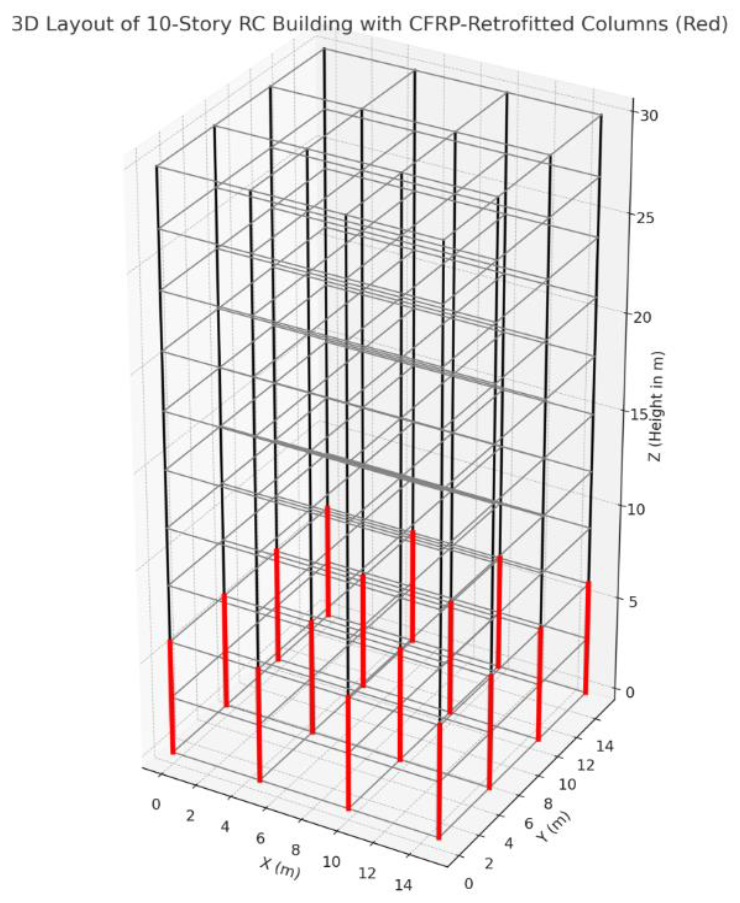
In this work, a 10-story regular RC building structure is modelled with a symmetric floor plan, where each floor is modeled as a degree-of-freedom (DOF) node. Each beam element is modeled in the dimension of , while column units are modeled in the dimension of . The height of each story was fixed at 3.2 meters that makes overall building height as 32 meters. Additionally, the bay width is standardized at 5 meters in both orthogonal directions, where each floor slab is designed as a rigid diaphragm. The proposed 10-storey building structure is modelled as a moment-resisting frame. The building materials are selected based on the IS 456:2000 and ACI 318-19 standards. With reference to the aforesaid standards the concrete’s compressive strength is fixed at 30 MPa, while steel yield strength is defined as 500 MPa. The elastic modulus of concrete is fixed at 5000 and the elastic modulus of steel is taken as 200 GPa. For CFRP material, the elastic modulus is taken as 230 Gpa, while the ultimate strength is taken as 3000 MPa. The initial thickness is considered as 0.2 and 1.5 mm. The value of is processed by the proposed MOGA driven NSGA-II optimization algoithm for rettrofitting optimization. It considers flexural stiffness, shear stiffness and tortional stiffness, while the damping was modelled by using Rayleigh damping, while Newmark-beta scheme was applied as integration mechanism to solve the non-linear dynamic system. Additionally, for simulation a lumped mass shear-flexural-tortional building model is designed. An illustration of the targeted 10-storey buiding is given in Figure 1.
For the nonlinear finite element formulation, the proposed structure (Figure 1) is modeled by using a two-dimensional (2D) frame idealization applying MATLAB 2022b tool. Each beam and column elements are formulated by applying a force-based nonlinear beam-column element with plastic hinge modeling at critical locations. The moment-curvature behavior of plastic hinges was obtained by using a bilinear idealization, given as (1).
In (1), represents curvature, while and state the ultimate moment and the yield moment, respectivelly. For damping and mass specifications, Rayleigh damping is considered (2). In equation (2), and state the mass and stiffness proportional coefficients.
The targeted 10-storey building structure is designed as lumped mass which is modelled by performing seismic weight distribution throughout the nodes.
Figure 1.
3D presentation of the targeted 10-storey RC building with CFRP-retrofitted columns.
4.3. Seismic Loading and Dynamic Time-History Analysis
Seismic analysis was performed using actual earthquake ground motion records, such as the El Centro accelerogram. A time interval of 0.02 seconds was adopted, and the seismic loading was evaluated over a duration of 30 seconds. The structural system was subjected to real earthquake data, specifically the 1940 El Centro and 1995 Kobe records. The ground acceleration histories were applied to the model through the effective load vector, expressed in equation (3) and further derived in equation (4). In this formulation, denotes the influence (or participation) factor.
The nonlinear Newmark-beta method was adopted as the time integration scheme in this study. The Newmark-beta approach is a widely used numerical technique for solving ordinary differential equations in structural dynamics, particularly suited for evaluating the seismic response of structures exhibiting nonlinear behavior. As an implicit integration scheme, it computes the current displacement and velocity based on future values, thereby ensuring numerical stability across a range of applications, including retrofitting scenarios. In this work, the method is employed to solve second-order differential equations governing the motion of vibrating systems under seismic excitation. Conceptually, the formulation originates from Newton’s second law, extended to represent a mass–spring–damper system subjected to external forces such as earthquake ground motions. The governing dynamic equilibrium equation for the retrofitted structure is expressed in (4).
In equation (4), denotes the displacement vector, while represents the ground acceleration. The present study employs the Newmark-beta integration scheme, which, in combination with nonlinear restoring forces, is iteratively updated to account for variations in material properties and retrofitting effects. A 10-story structural model was developed to analyze the corresponding dynamic responses, where the proposed framework integrates an AI-driven retrofitting strategy. This approach aims to determine an optimal CFRP retrofitting configuration capable of sustaining severe seismic events by reducing both the damage index and shear–torsional effects. A detailed description of the AI-based CFRP retrofitting methodology is presented in the following section.
4.4. Response Quantities
As response quantities for the dynamic analysis and corresponding retrofitting decisions, primarily four parameters were defined. These parameters are:
- —
- Roof Displacement
- —
- Inter-Story Drift
- —
- Hysteritic Energy
- —
- Damage Index
The details of these physical quantities and their use in at hand CFRP retrofitting problem are given in the subsequent sections.
4.4.1. Roof Displacement
This is the absolute displacement time history of the roof (top floor). It indicates how much the building sways during earthquakes — a direct measure of serviceability and collapse prevention. Mathematically, roof displacement is derived as (5), where be the global displacement matrix from Newmark.
In this work, peak roof displacement, also called the residual roof displacement is applied as a constraint to achieve optimal retrofitting condition.
4.4.2. Inter-Story Drift
Drift is the relative displacement between two consecutive floors. Typically, the drift ratio is the key seismic performance parameter in building codes (ASCE/IS/Eurocode). It states that the too large drift can damage structural/nonstructural elements. Mathematically,
In (7), story height. In the current retrofitting optimization problem, the focus is to minimize maximum drift ratio across stories and across ground motions. It is believed that for a seismic resilient multi-story building development, the inter-story drift must be below the code drift limit (e.g., 2% LS, 1% IO). Noticeably, based on the code like FEMA 356, ASCE 41, PEER guidelines, specific drift limits are assigned to performance levels. The typical drift thresholds are the immediate occupancy (IO), life safety (LS) and collapse prevention (CP). Here, IO indicates that the structure remains functional, minor damage. In this reference, the codes define IO limit as ≈ 0.5% – 1% drift. On the other hand, LS shows the significant damage but collapse is prevented. It’s limit is defined near 2%. On the other hand, the CP factor depicting the severe damage and structural (near) failur is required to be maintained within 4% drift.
4.4.3. Hysteretic Energy
It presents the energy dissipated in each story due to cyclic inelastic deformations (plastic hinges, CFRP-enhanced confinement). Typically, higher hysteretic energy shows better energy dissipation and hence lower demand on foundation. Mathematically, it is derived as (8).
In (8), represents the story shear force (also called restoring force), while be the incremental deformation. The incremental deformation along with the restoring force values, the damage index (DI) is calculated, which is later applied as a constraint for retrofitting optimization (as a minimizatio function, discussed later in the manuscript).
4.4.4. Damage Index
It is a scalar that combines deformation demand and energy dissipation demand, and indicates the severity of damage of each story (from 0 = undamaged, to 1 = collapse). In this work, Park Ang type of method. The detailed discussion of the method is given in the subsequent section.
Though, in addition to these parameters, six other cost functions are derived to perform at hand retrofitting problem as a multi-objective optimization problem. The objective functions and allied fitness function variables are given in the subsequent section. Thus, the proposed MOGA, an improved NSGA-II heuristic method measures discussed parameters iteratively and minimizes them to achieve an optimal set of retrofitting specifications for seismic resilient 10-storey building construction. The detailed discussion of the proposed MOO objective function is given in the subsequent section.
4.5. Multi-Objective Optimization Retrofitting (Fitness) Function
Unlike traditional retrofitting methods, the proposed method makes use of the MOO concept that intends to minimum structural deformations or defects while constraining retrofitting constructs or parameters. In other words, the proposed MOGA-driven NSGA-II optimization method at first achieve first objective function where it intends to minimize Park Ang damage index (), total retrofitting cost (), sustainability (i.e., carbon embedding ()), torsional irregularity index (), sensitivity to uncertainty () and peak floor acceleration for non-stationary elements (). Additionally, the proposed method intends to optimize retrofitting variables including mortar thickness, steel thickness, stiffness modification for each floor. The fitness functions are defined as follows:
where,
= Global Damage Index or Park Ang Damage Index,
= Total Retrofitting Cost,
= Peak Floor Acceleration,
= Torsional Irregularity Index and Inter-Storey Drift,
= Sensitivity to Uncertainty, and
= Total Carbon Embedding.
A brief of these key cost function factors is given in the subsequent sections.
4.5.1. Park Ang Damage Index
In this work, energy-based damage index often called the Park-Ang model was applied to measure Global Damage Index (GDI). The GDI value for each floor is measured as per the equation (9).
In (9), represents the peak deformation of storey , while be the ultimate defomration capacity. The parameter , be the cumulative hysterisis energy dissipated. The values represents the calibration constant which can exist in the range of 0.05 and 0.15. The proposed retrofitting model is designed in such manner that minimizes the GDI for each floor. Mathematically, it is defined as (10).
4.5.2. Total Retrofitting Cost
In this work, the total retrofitting cost is derived as per the equation (10), where the cost factor to be minimized is given as (12).
In equation (12), represents the cost pertaining to the bracing (design) structure, while CFRP be the one for the realization of the CFRP wrapping around of the colums. The cost pertaining to the total number of columns (), CFRP retrofit and the number of units and manpower costs aggregates the overall retrofitting costs. In (12), the initial component is obtained using the equation (13).
In eqution (14), represents the material and manpower cost per unit weight, used to be a fixed cost value related to the demolition and restoring works to connect bracings within the infill. In equation (13), represents the bracing weight in -th frame field, which is calculated according to the equation given in (14).
In equation (14), represents the length of steel brace, while represents the per unit weight of steel. represents a fixed cost related to the shear reinforcement of the terminals/ends of the columns near to the bracing systems to withstand the supplementary shear demand. The CFRP cost is calculated according to the equation (15).
In equation (15), and states the total number of retrofitted columns and unit cost pertaining to the CFRP wrapping. represents the cost per column that embodies the cost of demolition and reconstruction (pertaining to the plasters and masonries). The parameter represents the area of CFRP fabric applied to perform retrofitting of the -th column. It is finally derived as per the equation (16).
In equation (16), states the length of the -th column while and be the structural cross-sectional dimensions of each column. Here, represents the rounding radius of column edges.
4.5.3. Peak Roof Displacement
The absolute roof displacement under seismic loading is retrieved by solving the nonlinear MDOF dynamic equilibrium, given as (17).
In equation represents the floor replacement, while denotes the ground acceleration. The parameter be the restoring force including plastic offset . The other parameters, and represents the mass and damping matrices. To ensure reliability and seismic resilience the retrofitting model requires minimize roof displacement, as given in (18).
In (18), refers the roof displacement of the top storey.
4.5.4. Maximum Inter-Storey Drift Ratio (ISDR)
For each storey ,the drift is measured as per the equation (19), conditioned at at the ground level.
The inter-storey drift ratio (ISDR) is measured as (20).
In equation (21), represents the storey height. The proposed method intends to minimize the ISDR across all stories and times, and hence the objective function is defined as (21).
4.5.5. Sensitivity to Uncertainty
In the current seismic resilient CFRP retrofitting problem source of uncertainty can be due to the material properties, geometric parameters as well as seismic loading or seismic input. For instance, the material properties which often embody the concrete compressive strength (), steel yield strength (), CFRP modulus and tensile strength and mortar and jacketing strength. In the same manner, there can be the uncertainty due to the geometric parameters including the storey height, column or beam dimensions and CFRP thickness per storey. Additionally, the seismic inputs such as the ground motion intensity, frequency content, duration etc. too can have the impact on retrofitting performance. To address it, it is must to nullify such outcomes (say, sensitivity) caused due to the uncertainties. In the proposed simulation model, Monte Carlo sampling was performed around 10% for the stiffness (), strength and CFRP modulus . Thus, the sensitivity can be derived from these parameters in the form of the coefficient of variation (COV), given in (22). Here, COV is measured for each response metric (roof drift, base shear and ductility).
Though, in addition to the above formulation, derivative-based sensitivity can also be obtained by applying approximate partial derivatives , which show the extent to which the drift changes per percentage in CFRP modulus. To be noted, in case of the baseline RC showing high sensitivity to uncertainties (e.g., small reduction in concrete strength and hence big increase in drift), it can make the structure more fragile. On the other hand, if the optimized CFRP wrapping reduces sensitivity (narrower spread of response distributions, lower COV), it means it stabilizes performance under uncertain conditions.
In MOO driven CFRP retrofitting problem, sensitivity to uncertainty is considered as one of the objectives. It can be defined as (23).
It can also be derived as a normalized sensitivity index, given in (24).
In (24), shows the responses (i.e., roof shift, shear, etc.) under Monte Carlo perturbations. In the proposed retrofitting problem, both mean response as well as uncertainty sensitivity is minimized and optimized to achieve an optimal seismic resilience of the targeted 10-storey structure.
4.5.6. Total Carbon Embedding
It is the CO₂-equivalent emissions associated with producing, transporting, and installing construction materials. For the present CFRP retrofitting problem, the predominant contributors of carbon emission are the CFRP laminate/fabric (resin + carbon fibers), mortar or adhesive for bonding, steel (if jacketing is used) and concrete repair/patching. Here, it is measured in kgCO₂e per unit volume, mass, or area. To maintain sustainability goal, the proposed method intends to minimize total carbon embedding. Recalling the retrofitting problem, where the CFRP variables are like (CFRP) thickness, orientation and coverage per story in the targeted 1-storey structure. The carbon emission is measured as per the equation (25).
In (25), be the volume used per storey (it depends on the CFRP thickness and coverage), density , while be the emission factor (. Thus, the total carbon emission or carbon embedding is measured as per the equation (26).
The proposed retrofitting model intends to minimize the carbon emission value (26).
Thus, in reference to the above stated parameters, the optimization problem is defined as a minimization function, given in (28).
Thus, applying the derived fitness function and allied objective function, the proposed MOGA driven NSGA-II optimization algorithm optimizes the retrofitting parameters while turning the following (input) parameters:
- —
- Mortar thickness
- —
- Steel thickness
- —
- Wrapping flags
- —
- Storey stiffness modifiers
- —
- CFRP Orientation.
Thus, tuning the above stated design parameters, the overall target objectives are fulfilled. In the proposed NSGA-II method, fitness is not a single scalar but a Pareto ranking of solution. Yet, for clarity, the fitness vector is defined as (20), where the proposed MOGA model intends to the achieve a Pareto-optimal set, given as (29).
The proposed research performs CFRP wrapping and CFRP-Steel retrofitting to achieve target seismic performance. For the CFRP wrapping, a confinement effect was proposed by realizing the Mader model, where the improvement of flexural and shear capacity was done by increasing modulus. The proposed MOGA-driven NSGA-II heuristic model was designed and executed in such manner that it tuned the wrapping configuration and thickness while minimizing objective functions as derived in (28). The proposed method also minimized torsional-shear effects so as to retain structural stability under seismic loads. In the proposed optimization framework, steel jacketing was modeled with the added stiffness and yield strength to both beam as well as column elements. Here, the jacketing mechanism includes modeling of slip and interface deformation by applying bilinear behavior. Amalgamating the advantages of both CFRP wrapping and steel jacketing the CFRP-steel retrofit model was formulated. Noticeably, each retrofitting method impacts the global stiffness matrix , damping matrix , and mass matrix . The damping matrix states the proportional damping denoting resdual energy dissipation via internal material damping. Here, is calculated as inter-story lateral stiffness, which has been used to claculate yield displacement of each story in the targeted 10-story building. CFRP jackets are used to the columns for confinement and flexural enhancement. In this process, the effects are modeled by updating the moment-curvature response and confinement-enhanced strength as per the Mander model and ACI 440.2R-17. The confinement model for concrete intends to improve compressive strength of concrete, where the confinement model for concrete is defined as per the equation (30).
In equation (30), , and be the effectiveness factor, defined as 0.9. The flexural strength is improved by using the below formulation (31).
In equation (31), is measured from the strain compatibility of CFRP and steel at the seismic load. To achieve the targeted seismic resilient retrofitting decision, the proposed method applied MOGA heuristic method, an improved NSGA-II algorithm. A brief of this optimization method is given in the subsequent section.
4.6. MOGA (NSGA-II) Based Retrofitting Modeling
To achieve an effective CFRP RC retrofitted structure, the proposed method performs heuristic driven MOO optimization method where the focus is made on reducing damage index and retrofitting cost. To achieve it, the proposed heuristic model optimizes CFRP thickness , steel jacket thickness , orientation angles and wrapping configurations dynamically (continuous or discrete). Unlike traditional methods where the authors have applied either retrofitting cost or damage index as objective function, in this work a total of six cost function factor (say, fitness functions) as depicted in (28) are applied. Here, the objective function (28) is defined as a minimization function, which is reduced iteratively while tuning or optimizing design specifications such as the thickness, steel jacket thickness, mortar etc. on each storey. This is the matter of fact that selecting an optimal set of CFRP design specifications under dynamic load vector remains a complex problem and challenging. Being an NP-hard problem, it requires heuristic algorithm(s) to tune or optimize the CFRP wrapping and jacketing structure(s) for the different floors to bear seismic loading. Additionally, optimizing CFRP specifications with multiple objectives (28) requires optimization to be framed as a MOO problem. The MOGA heuristic model, which is designed as an improved NSGA-II heuristic optimizes CFRP retrofitting under dynamic conditions. To achieve it, GA optimization routine is developed in MATLAB.
Genetic Algorithm (GA) is a metaheuristic optimization approach inspired by the theory of evolution and Darwin’s principle of survival of the fittest. It explores the search space by evaluating the objective function at discrete points and iteratively progresses toward the minima based on a predefined set of design parameters, referred to as genomes, which govern performance in each generation. The GA framework generates a population of candidate solutions, each representing a potential retrofitting configuration that satisfies the specified performance requirements. In this study, each individual solution is defined by a design vector comprising the parameters to be optimized. For the CFRP-based retrofitting of multi-story structures, these parameters include the location of reinforcement interventions, specifying both the structural elements to be strengthened and the extent of reinforcement applied. The Multi-Objective Genetic Algorithm (MOGA) formulation incorporates a set of objective functions that account for retrofitting cost as well as structural performance under seismic loading. The suitability of each candidate solution is evaluated through nonlinear pushover analysis, which determines structural performance across various limit states. Correspondingly, the fitness function assesses seismic safety in terms of damage index and compliance with code requirements.
During each iteration, the MOGA scheme minimizes the objective functions (28) while applying the target fitness values as constraints. The optimization process yields an optimal CFRP retrofitting configuration for the ten-story RC building that achieves minimum damage index and reduced cost, while simultaneously mitigating shear–torsional effects. The overall workflow of the proposed optimization framework is illustrated in Figure 2. The optimization process employs a modified GA algorithm (NSGA-II) to enhance search efficiency. An initial population of random individuals, encoded as design vectors, is generated and evaluated for fitness and constraint violations. The parent selection operator identifies the best candidates for reproduction, where a set of modified or tunes solution vectors are generated to meet retrofitting demands in each iteration. Crossover combines the genetic material of top individuals, while mutation introduces minor random perturbations to prevent premature convergence. Survival selection then retains the most fit or suitable individuals from both the current and previous generations. The process iterates until a stopping criteria is met. In this work, the stopping criteria is defined as the number of generations (here, 200). The overall NSGA-II algorithm mechanism is depicted in Figure 3, while the detailed implementations of the genetic operators are presented in subsequent sections. To be noted, in this work the initial values of the crossover probability and the mutation probability are defined as 0.8 and 0.2, respectively.
A brief of the proposed NSGA-II optimization function is given as follows: functions employed in the proposed GA method is given as follows:
Parent selection operator
Parent selection is a crucial step in evolutionary optimization, as it determines the individuals that will undergo genetic operations namely crossover and mutation to produce the next generation. In this study, a tournament selection strategy is employed. Under this mechanism, individuals are randomly sampled from the population, and the most suitable candidate is selected as the parent. The selection process follows a two-level criterion: (i) minimizing the number of constraint violations, and (ii) maximizing the fitness value among individuals with equivalent violation counts. The parameter , referred to as the tournament size, governs the selection pressure. A larger intensifies the preference toward high-performing solutions, whereas a smaller increases the likelihood of selecting comparatively weaker candidates.
Crossover and Mutation
Crossover and mutation operators are employed to generate offspring and improve genome diversity across successive generations. The crossover operator combines genetic information from two parent solutions, whereas the mutation operator introduces stochastic alterations to maintain variability in the population. In this study, a customized crossover scheme is implemented to handle heterogeneous genomes consisting of both natural-number and Boolean variables. For natural decision variables, a random intermediate crossover is applied, where each gene is assigned a value randomly selected between the corresponding parental entries (inclusive), thereby balancing similarity preservation with diversity enhancement. For Boolean variables, a single-point crossover is utilized, in which a randomly chosen point divides the genetic string, and segments are inherited from the respective parents. The crossover and mutation probabilities are set at 0.8 and 0.2, respectively. Mutation is executed by randomly selecting one or more positions within the design vector and altering their values, either by assigning a new feasible random value for discrete variables or by flipping the binary state in Boolean genes. Distinct from conventional GA implementations, this work applies crossover and mutation in an alternating manner, rather than sequentially, to generate new individuals.
Unlike traditional GA methods, since the proposed research intended to minimize fitness function set (28) while constraining retrofitting specifications (say, optimization). To propagate high-quality genomes, the initial population is merged with offspring and subjected to a sorting and truncation survival selection. Individuals (i.e., the solutions) are first sorted by the number of violated constraints, then by fitness within equally constrained groups. The best solution, positioned at the start of the sorted list, are retained, while the remainder are discarded. It effectively manages constrained optimization without penalty functions, avoiding the complexity of penalty weight calibration while maintaining robustness, albeit with potentially lower peak performance. A heuristic repair routine is applied that alters the design vector to enforce predefined variable values under specific conditions. It ensures shear reinforcement for side columns of braced spans by introducing CFRP reinforcement into the design vector if absent. The routine identifies bracing positions and adjusts vector so that columns adjacent to the braces receive reinforcement with the same spacing and number of layers specified within the design vector.
Unlike traditional GA-based retrofitting routing, this research designed MOGA to act as an improved NSGA-II heuristic. A brief of this method is given as follows:
The NSGA-II is one of the most widely adopted multi-objective optimization techniques, with proven adaptability across a range of fields. Its general workflow begins with the random generation of an initial population of size , followed by evaluation against two or more fitness functions (28). Individuals are then classified into successive non-dominated layers, termed non-domination ranks (, with representing the non-dominated set. Genetic operators, as discussed above, embody binary tournament selection, crossover, and mutation are subsequently applied to generate an offspring population of size , which is also evaluated. Parent and offspring solutions are merged into an extended population of size , which is again sorted into layers. The next generation is constructed by selecting the top individuals from these layers. Elitism ensures that all first-front solutions are preserved, while additional individuals are chosen from subsequent layers until the target size is met. When a layer exceeds the remaining slots, crowding distance is applied to favor individuals in sparsely populated regions, thereby maintaining diversity across the Pareto frontier. This cycle continues until the stopping criterion is reached, with multiple independent runs commonly performed to ensure a robust approximation of the Pareto set. Although NSGA-II was introduced more than two decades ago, it continues to achieve state-of-the-art performance due to its balance between convergence and diversity. Prior applications in structural engineering include the optimization of cross-laminated timber–concrete composite floors with respect to thickness, weight, and cost [108]; the design of BRB-reinforced concrete space frames minimizing interstory drift and cost [109]; and the seismic design of irregular steel frames with BRBs reinforced concrete onsidering both cost and hysteretic energy ratio [110]. In sustainable design, it has been applied to optimize the energy performance of residential buildings using ten design variables and three objectives related to thermal discomfort and energy demand for heating/cooling [111]. In contrast to these applications, the present study introduces a novel integration of NSGA-II with an AI-driven CFRP retrofitting framework for multi-story reinforced concrete buildings. Unlike traditional uses of NSGA-II in material selection or structural layout optimization, this work targets seismic resilience by simultaneously minimizing structural damage indices, intervention costs, and shear–torsional effects. This represents a new dimension of application for NSGA-II, extending its utility to advanced retrofitting strategies in earthquake engineering.
The pseudocode of NSGA-II is provided below, and its general workflow is given as follows:
| Algorithm 1. NSGA-II Procedure. |
|
Input: Population size , maximum generations , fitness functions . Output: Approximation of Pareto-optimal front. |
| 1. Initialization 1.1 Generate an initial population of size at random. 1.2 Evaluate all individuals using the fitness functions F (28). 1.3 Perform non-dominated sorting to classify individuals into fronts. 1.4 Assign a non-domination rank () to each individual. 1.5 Generate offspring population of size using binary tournament selection, crossover, and mutation operators. 2. Evolutionary Loop (for t = 1 to T) 2.1 Combine parent and offspring populations: . 2.2 Perform non-dominated sorting on . 2.3 Assign ranks based on Pareto dominance. 2.4 Select individuals to form the next generation P_(t+1), starting from the best front until N individuals are chosen. 2.5 If the last front exceeds available slots, compute crowding distance and select the least crowded solutions to maintain diversity. 2.6 Generate offspring using genetic operators (binary tournament, crossover, mutation). 3. Termination Stop when the target number of generations is reached. The non-dominated solutions in the final population approximate the Pareto front. |
Thus, applying this method the overall proposed CFRP retrofitting was achieved. The simulation results and allied inferences are given in the subsequent sections.
5. Results and Discussion
This research proposed a robust heuristically optimized AI framework for CFRP retrofitting for seismic resilient multi-storey (building) development. Realizing non-linearity of seismic loading and resulting drift probability on the different stories, this work focused on multiple aspects including whether to perform CFRP wrapping on certain floor or not. Additionally, it also optimized retrofitting specifications if needed so as to retain optimal seismic resilience while guaranteeing reliability as well as sustainability. Unlike traditional CFRP retrofitting methods where the authors primarily focused on retrofitting cost minimization or damage reduction, this research defined CFRP retrofitting as a MOO problem that intended to minimize multiple fitness functions including damage index, total retrofitting cost, carbon embedding, torsional irregularity, sensitivity to uncertainty and peak floor acceleration. This research hypothesized that maintaining minimum objective functions as stated above can help to retain optimal CFRP specifications like CFRP wrapping thickness, mortar thickness, retrofitting orientation etc. More specifically, this research proposed a novel and robust MOGA heuristic model developed on the basis of the NSGA-II heuristic optimization concept for CFRP retrofitting in seismic resilient and sustainable (low-carbon) 10-story building. A brief of the structural details is given in Table 1. The proposed research at first performed non-linear time-history analysis by applying MOGA so as to achieve an optimal set of CFRP retrofitting condition. The proposed retrofitting method at first enables assessing whether a floor out of the 10-floor or 10-storey building requires CFRP wrapping, mortar jacketing and steel jacketing. In addition, it identifies an optimal set of CFRP wrapping conditions including the (CFRP) thickness, orientation, design patterns (i.e., unilinear, bidirectional and hybrid), coverage and anchors etc. These seismic resilient CFRP use-conditions were achieved while minimizing overall costs (i.e., CFRP, resin, steel and mortar), torsional irregularity index (i.e., per floor drift and torsional surrogate), Park Ang damage index and sensitivity towards seismic loading. CFRP wrapping is performed while constraining non-structural elements or content that improves reliability of the overall vertical structure under seismic loading conditions. With the given input structural and geometric specifications (Table 1), the proposed NSGA-II driven MOGA model performs dynamic analysis to approximate the retrofitting parameters while meeting expected seismic resilience and allied objectives. In this method, the seismic performance is examined by applying time-history simulation under real ground motion data collected from El-Centro earthquake dataset (1942). The proposed method at first makes use of a benchmark seismic loading data named “El Centro earthquake ground motion record” comprising time-history acceleration data obtained from the 1940 EL Centro Earthquake (imperial valley, California). The time-analysis data comprises two columns, time (s) and acceleration (g), where the later signifies ground acceleration values in terms of gravity (g). In this manner, exploiting the ground motion excitation, material and structural nonlinearities, CFRP material selection, wrapping thickness, and orientation, the proposed model reconfigures CFRP layer with other aspects including CFRP material selection, orientation etc.
In order to examine efficacy of the proposed CFRP retrofitting model, a 10-storey concrete building is simulated. To achieve it, a 10-storey building is modelled as lumped mass multi-degree-of-freedom (MDOF) system. The non-linearities throughout the (builder) structure over floors are obtained retrieved by means of bilinear hysteresis, where the system was subjected to El Centro ground motion.

Table 1.
Structural Configurations.
| Parameter | Specification |
|---|---|
| Building Type | 10-story reinforced concrete (RC) frame |
| Mass Matrix | Diagonal, uniform mass of 10,000 kg per story |
| Stiffness Matrix | Inter-story stiffness of 1.5×10⁷ N/m |
| Damping Ratio | 5% equivalent viscous damping applied using Rayleigh damping |
| Initial Yield Strength (Fy) | 120,000 N for each story |
There exist three different types of CFRP retrofitting materials including unidirectional, bidirectional and hybrid CFRP models; yet, the efficacy of hybrid CFRP and/or bidirectional CFRP materials exhibit superior. As empirical verification, in this work the simulations were done with the different CFRP material types. Noticeably, bidirectional CFRP fabric, also known as a twill weave, has carbon fibers woven in two directions (warp and weft) for balanced strength and flexibility, making it suitable for applications requiring strength in multiple directions. The hybrid CFRP on the other hand signifies the carbon fiber reinforced polymer composites that combine carbon fibers with other materials, like glass fibers or steel, to create a material with enhanced properties like improved ductility, damage resistance, and tailored mechanical behavior. The unidirectional CFRP (carbon fiber reinforced polymer) represents a kind of composite material where all the carbon fibers within the material are aligned in the same, parallel direction, providing the highest strength and stiffness along that specific axis. In reference to the above discussed inferences, the proposed method simulated retrofitting model with the different types of fiber models, and corresponding performances were examined. A brief of the CFRP design is given in Table 2.
In reference to the input geometric and material properties, retrofitting configuration, seismic inputs, the proposed retrofitting method executes NSGA-II driven MOGA model to optimize retrofitting specifications for the targeted 1-storey building. The proposed NSGA-II model was designed and executed with the total number of initial populations as 100, while crossover and mutation coefficients were decided as 0.8 and 0.2, correspondingly. As already discussed, the proposed NSGA-II driven MOGA heuristic model optimizes retrofitting specifications while minimizing the cumulative fitness function embodying damage index, total retrofitting cost, carbon embedding, torsional irregularity, sensitivity to uncertainty and peak floor acceleration. Estimating the initial CFRP retrofitting specifications, fitness functions, MOGA NSGA-II model exploited Pareto-optimal trade-offs between performance and objective function to achieve an optimal set of CFRP retrofitting specifications to meet seismic resilient 10-storey building construction. Functionally, the proposed method designs a fitness evaluation function (non-linear Multiple DOF) that examines dynamic response to calculate TDI, cost, and ductility for each candidate solution. During optimization, the proposed method measures and learns over the key factors or metrics like damage index per story, top floor displacement, inter-story drift over time, force-displacement hysteresis, energy dissipation per story, ductility ratio, latent stiffness evolution and seismic load capacity and horizontal bearing. Learning over these parameters, the proposed model yields an optimal set of CFRP material and corresponding retrofitting specifications per floor, that enables expected target performance under (non-linear) seismic loading conditions.
Figure 4 depicts the comparison of the damage responses towards the intended 10-storey reinforced concrete frame structure in its baseline condition as well as post CFRP-based seismic retrofitting with optimization. As depicted, the baseline system undergoes larger scatter in the computed damage indices throughput the uncertainty realizations, indicating the sensitivity of the un-retrofitted frame to variations in ground motion intensity, material degradation, and modeling assumptions. On the contrary, the optimized CFRP configuration exhibits a decisive reduction in both the mean damage index as well as the spread of uncertainty bands. The outcomes show that the CFRP orientation and thickness distribution identified by the MOGA model reduces inter-story drifts and hysteretic degradation decisively, which directly lowers cumulative damage. The simulation result (Figure 4) also indicates that the retrofitted system exhibits smaller variability across simulations, exhibiting reduced sensitivity to the fluctuations in concrete compressive strength, steel yield strength, and ground motion variability. Such robustness is vital for seismic resilience, as design safety must hold across a wide spectrum of demand and material variability rather than for a single deterministic case. In summary, the simulation results affirm that the proposed MOO optimization not only improves the structural safety margin but also enables robust seismic performance under uncertainty, making the retrofit both effective and reliable.
Figure 5 (1-c) exhibits the optimized distribution of CFRP retrofitting parameters across the 10-storey RC frame, achieved by means of the proposed MOO optimization framework (here, NSGA-II driven MOGA). The result (Figure 5) shows the simulation outputs in terms of the orientation angle of CFRP fibers, the laminate thickness, and the coverage ratio on each storey. As depicted in Figure 5(a), the fiber orientation varies between approximately 30° and 65° along the height. Lower storeys generally adopt higher orientations (closer to 60°), favoring shear resistance where lateral demands are higher, while upper storeys tend to employ smaller angles (around 40°), where flexural demands dominate. This reflects the optimization algorithm’s ability to balance local seismic demand with material efficiency. On the other hand, Figure 5(b) indicates a non-uniform thickness distribution, with certain storeys (e.g., 2nd and 8th) requiring up to 3 mm of CFRP, while others maintain only ~2 mm. It infers that the optimizer assigns additional confinement and flexural strength at critical storeys where inter-story drifts are concentrated, thereby minimizing damage propagation. The performance quantification in terms of the coverage ratio (Figure 5(c)) reveals that the coverage values mostly lie between 0.7 and 1.0, with reduced coverage (≈0.5) at select mid-storeys. This indicates that full wrapping is not necessary at every level to achieve seismic resilience. Instead, partial wrapping at less critical storeys contributes to cost savings without significantly compromising performance. The overall result (Figure 5) exhibits that the proposed NSGA-II driven MOO optimized retrofit scheme is non-uniform and demand-driven, rather than uniform across the building. Such an adaptive allocation of CFRP resources ensures that seismic performance is enhanced where needed most, while minimizing material usage and associated costs.
The Pareto front illustrated in Figure 6 exhibits the MOO optimization outcomes of the retrofitted 10-storey RC structure under seismic loading. The horizontal axis indicates the retrofitting cost, while the vertical axis shows the structural damage index, and the color gradient corresponds to the embodied carbon emissions (CO₂) associated with the retrofit materials and configurations. The simulation result (Figure 6) indicates that the lower damage indices (below 10–15%) are achievable, but they require substantially higher retrofitting investments, with costs rising towards 40,000–50,000 units. Conversely, inexpensive solutions (cost < 10,000 units) are associated with higher seismic damage levels (up to 60–65%), indicating under-strength or insufficient CFRP reinforcement. In terms of carbon sensitivity, the simulation results show that the solutions with higher embodied carbon (yellow region) align with low-damage and high-cost retrofits, whereas low-carbon options (blue–green region) cluster at the moderate to high damage range. This underscores a clear sustainability-performance conflict, where reducing seismic damage generally leads to increased material consumption and carbon emissions. Interestingly, the mid-range solutions (cost ≈ 20,000–30,000 units, damage ≈ 10–20%, carbon ≈ 4000–7000) reflect a balanced retrofitting strategy. These solutions provide substantial seismic resilience improvements while keeping both cost and carbon footprints within manageable bounds, making them promising candidates for practical adoption in real-world seismic retrofitting projects. Summarily, the result (Figure 6) depicting the Pareto analysis confirms the efficacy of the proposed CFRP retrofitting optimization framework, as it provides stakeholders with a decision-making spectrum that balances structural safety, economic feasibility, and environmental sustainability. Based on the work priorities, whether resilience, cost-efficiency, or carbon reduction, the decision-maker can select an optimal configuration from the Pareto set.
Figure 7 shows the comparison of the damage index for two scenarios, baseline and optimized over the CFRP retrofitting of a 10-story building, with uncertainty considerations incorporated into the damage assessment. The damage index quantifies the structural damage incurred under seismic loading, where a higher value represents greater damage. In this study, the MOGA and NSGA-II have been employed to optimize the retrofitting design using CFRP materials, with the aim of reducing both damage and uncertainty. The baseline scenario, depicting the initial unoptimized state of the building, exhibits a high damage index (approximately 70). This result is accompanied by significant uncertainty, indicated by the error bars, reflecting the variability in the damage index due to factors such as material properties, seismic load variations, and modeling uncertainties. On the contrary, the optimized scenario, where the building is retrofitted using CFRP materials, depicts a massive reduction in the damage index to around 10, accompanied by much smaller error bars. The reduction in both the damage index and the associated uncertainty underscores the effectiveness of the optimization process. The proposed NSGA-II-based optimization has successfully balanced multiple objectives, including minimizing structural damage while considering uncertainties in the design and material properties. Noticeably, the error bars in both cases depict the uncertainty in the damage index, which might be caused from the different sources, including inaccuracies in material modeling, load assumptions, or the variability of CFRP properties. The optimized retrofitting strategy has not only reduced the overall damage but has also minimized the uncertainty in the damage prediction, thereby enhancing the reliability and confidence in the structural design. Figure 7 shows the critical impact of optimization techniques like MOGA and NSGA-II in improving the retrofitting design, demonstrating a substantial reduction in damage while managing the inherent uncertainties associated with complex structural interventions.
This scatter plot (Figure 8) shows the association between the average CFRP thickness employed to the 10-story building and the resulting seismic damage index, quantifying the building's damage under seismic loading. The damage index (vertical axis) indicates the level of structural damage, where a higher value corresponds to more damage, and the average CFRP thickness (horizontal axis) represents the retrofitting thickness applied to the building’s structural components. The simulation result (Figure 8) illustrates a clear trend confirming that: as the CFRP thickness increases, the damage index decreases, demonstrating the effectiveness of the CFRP retrofitting in reducing seismic damage. For lower CFRP thicknesses (less than 0.5 mm), the damage index remains relatively high, indicating insufficient seismic protection. However, as the thickness of the CFRP increases to approximately 1 mm and beyond, there is a noticeable drop in the damage index, reaching a minimum threshold at around 2 mm. This suggests that a critical CFRP thickness exists, where the retrofitting intervention becomes highly effective at minimizing seismic damage. Interestingly, the color bar on the right represents the magnitude of the seismic damage, with cooler colors (blue) indicating lower damage and warmer colors (yellow) corresponding to higher damage. This gradient further emphasizes the reduction in damage as the CFRP thickness increases, highlighting the correlation between material application and seismic resilience. The overall findings are crucial for optimizing the retrofitting design, balancing the effectiveness of the CFRP material with cost considerations. The MOGA and NSGA-II optimization algorithms, employed in this study, help identify the optimal CFRP thickness that minimizes damage while considering other design objectives, such as material usage and cost efficiency. The results validate the critical role of proper CFRP thickness in enhancing the structural integrity of retrofitted buildings, particularly under seismic loading conditions.
The Figure 9 shows the Pareto front analysis depicting the trade-off between retrofit cost and resulting damage index for the CFRP retrofitting solutions of the 10-story building. Here, each point relates to a nondominated design, signifying no other solution simultaneously achieves both lower cost and lower damage index. In the lower-cost segment, small increments in cost result in large reductions in damage, depicting strong marginal gains for modest additional investment. However, as one moves to the mid and upper cost range, the slope of reduction in damage becomes much flatter, indicating diminishing returns: further cost increases deliver only marginal improvements in damage mitigation. The “knee” or inflection of the front is thus particularly noteworthy, as it suggests the most efficient balance between investment and performance. From a decision-making standpoint, a stakeholder may select a Pareto point just beyond the knee to balance affordability and resilience: for example, investing up to cost yields most of the achievable damage reduction, while avoiding disproportionately expensive designs. Conversely, in safety-critical settings, one might choose a more conservative (higher cost, lower damage) solution, accepting diminishing returns in cost. Importantly, because the damage indices in this study are computed under uncertainty (e.g., in seismic demand, material variability, CFRP effectiveness), each Pareto point implicitly represents a robust trade-off in an uncertain design space. In this sense, the Pareto front derived via NSGA-II / MOGA not only maps mean trade-offs but also helps identify retrofit strategies that are least sensitive to perturbations. The diversity of optimal candidates affirms that the optimization algorithm effectively explored the design space, consistent with prior MOO retrofit studies.
Figure 10 shows the box plot for the comparison of the distribution of the Damage Index for the baseline (un-retrofitted) structure and the optimized structure obtained through the proposed NSGA-II driven MOGA optimization model. As depicted in Figure 10, in case of baseline case the damage index values are concentrated at higher levels, with a median close to 75 and an upper bound near 80. This reflects severe seismic vulnerability when no CFRP retrofitting is applied. The relatively wider spread indicates that the baseline structure exhibits significant sensitivity to input uncertainties, such as ground motion variability and modeling assumptions. On the contrary, in case of NSGA-II driven MOGA optimization model the simulation result (Figure 10) shows that post retrofitting (optimized), the damage index reduces drastically to below 10. Notably, the spread of the data becomes minimal, suggesting that the optimized solution not only minimizes expected seismic damage but also improves robustness under uncertainty. This trend can be attributed to the effective placement and proportioning of CFRP layers, which enhance both stiffness and energy dissipation capacity. The multi-objective optimization ensures that strengthening is balanced with material efficiency, leading to both reduced median damage and lower dispersion across uncertain seismic scenarios. From a structural performance standpoint, this indicates that the retrofitted building is far less likely to enter high-damage states, even when subjected to a range of seismic inputs. The results comparison clearly shows that while the baseline case reflects the inherent fragility of the structure, the optimized case demonstrates that advanced CFRP retrofitting guided by NSGA-II can yield not just lower seismic demand but also a much more predictable response. This reliability aspect is crucial for real-world adoption, where seismic hazard uncertainty cannot be fully eliminated.
The scatter plot, as depicted in Figure 11 shows the Pareto-optimal trade-off solutions between retrofit cost and embodied carbon for the CFRP retrofit strategy of the 10-storey building. Each point corresponds to a non-dominated solution identified by the NSGA-II algorithm. The solution shows a clear inverse relationship between retrofit cost and embodied carbon. Low-cost solutions are associated with significantly higher embodied carbon values, whereas solutions with reduced embodied carbon tend to involve higher retrofit costs. On the other hand, the clustering aspect clearly indicates a dense concentration of points at the lower end of retrofit cost, suggesting that inexpensive strengthening schemes can be achieved but at the expense of environmental sustainability. Conversely, solutions with costs in the 30–60 range correspond to markedly reduced embodied carbon, highlighting the environmental benefit of optimized material deployment. This trade-off arises because minimizing cost typically favors minimal CFRP usage, which may require thicker or less sustainable material options to meet structural performance targets. On the other hand, minimizing embodied carbon leads to solutions that distribute CFRP more efficiently, but the design complexity and increased coverage drive up the overall retrofit cost. The NSGA-II heuristic is effective here, as it captures a wide set of non-dominated alternatives that reflect these competing objectives. The result (Figure 11) provides a decision-making framework for stakeholders. Depending on project priorities, one may select a retrofit solution that is cost-optimal, carbon-optimal, or an appropriate compromise between the two. Importantly, the spread of solutions demonstrates that CFRP retrofitting is not a single-solution problem but rather a spectrum of possibilities where economic and environmental considerations must be balanced.
Figure 12 shows the Pareto-optimal solutions obtained through NSGA-II, where torsional irregularity index is plotted against the damage index. Each point reflects a retrofit design configuration that balances these competing objectives. The data suggests a nonlinear relationship between torsional irregularity and damage index. Some solutions with relatively low torsional irregularity still correspond to higher damage indices, while others with slightly higher torsional irregularity achieve significantly reduced damage. This indicates that torsional control alone does not directly guarantee minimum seismic damage. The distribution outcomes clearly shows that the solutions are spread across a narrow range of torsional irregularity (≈1.57–1.65), signifying that the optimization converges toward retrofit schemes that maintain structural symmetry within acceptable code-defined limits. Within this constrained range, however, the damage index varies widely, from nearly zero up to ~5×10⁴. The measured changes primarily arise from the complex interaction between torsional response and global seismic demand. CFRP retrofitting influences not just the torsional stiffness but also the overall lateral stiffness distribution and energy dissipation capacity. As a result, a design that reduces torsional irregularity may not always minimize the damage index if it sacrifices strength or ductility in other directions. The Pareto set, therefore, highlights the need for multi-criteria balancing rather than focusing exclusively on a single structural irregularity parameter. The simulation result (Figure 12) underscores the practical advantage of heuristic optimization over conventional retrofit design. By exploring a wide solution space, NSGA-II identifies retrofitting schemes where torsional irregularity is controlled without excessively increasing damage, and vice versa. For decision-makers, the Pareto front provides a set of viable alternatives depending on whether the retrofit priority is torsional balance (to meet code requirements) or damage minimization (to enhance seismic resilience).
Figure 13 compares the roof displacement response of the 10-storey building under seismic excitation, before and after applying the optimized CFRP retrofit. In reference to the baseline (red curve), the un-retrofitted structure undergoes large amplitude oscillations, with peak displacements exceeding ±0.01 m. The periodic pattern reflects resonance with the applied ground motion, leading to sustained and significant roof-level displacements. The simulation result depicting the optimized retrofitting case (blue curve) indicate that the retrofitted structure shows markedly reduced displacement amplitudes, generally confined within ±0.004 m.
The frequency content is preserved, but the response magnitude is substantially dampened, demonstrating enhanced stiffness and energy dissipation due to CFRP strengthening. The reduction in displacement can be attributed to two key effects of the optimized retrofit strategy, first the increased lateral stiffness from CFRP confinement and reinforcement, which raises the effective natural frequency and reduces resonance amplification. Second, the improved damping capacity, as the optimized CFRP distribution enhances energy absorption during cyclic loading, thereby lowering the response amplitude across successive cycles. The fact that the optimized curve remains consistently bounded, without significant drift or amplification, indicates that the proposed heuristically optimized retrofitting solution has successfully balanced retrofit cost, material use, and seismic performance. The simulation output (Figure 13) provides direct evidence of the practical effectiveness of the optimization framework. By reducing roof displacement, the retrofit not only improves serviceability performance but also limits damage accumulation during seismic events. Since roof displacement is strongly correlated with inter-storey drifts and overall seismic vulnerability, the improvement observed here validates the design outcomes of the heuristic optimization.
Figure 14 shows the comparison of the inter-storey drift ratios for the baseline and optimized cases across all storeys of the targeted 10-storey building. As depicted in the results, the un-retrofitted structure shows decisive drift concentrations at the first and top storeys (), with intermediate storeys showing progressively lower but still notable values. This “soft-storey” type distribution indicates localized weakness at the lower levels and excessive flexibility at the roof, both of which are highly undesirable in seismic design. On the other hand, with the optimized case following the MOGA–NSGA-II guided CFRP retrofit, drift ratios are drastically reduced across all storeys, with values staying well below . The reduction is most pronounced at the first and top storeys, where the baseline structure exhibited peak vulnerability. The dramatic drift reduction reflects the effectiveness of CFRP confinement and reinforcement in enhancing lateral stiffness and distributing seismic demand more uniformly across storeys.
By strategically placing CFRP layers, the optimization reduces weak-storey effects and prevents concentration of damage at specific levels. Furthermore, the smoother drift profile indicates that the optimized structure responds in a more uniform and ductile manner, avoiding abrupt stiffness irregularities that can trigger collapse mechanisms. Controlling inter-storey drift is vital because it directly correlates with damage to non-structural components (such as partition walls and facades) and ensures compliance with performance-based seismic design criteria. Figure 14 provides strong evidence that the heuristic optimization not only reduces overall seismic demand but also delivers tangible improvements in occupant safety, serviceability, and resilience of the retrofitted structure.
Figure 15 compares the hysteretic response of the baseline and optimized structures under cyclic loading, with base shear plotted against roof displacement. The simulation outputs clearly indicates that the un-retrofitted structure shows a wider hysteresis loop, with larger displacement excursions at relatively high base shear values. The curve displays significant energy dissipation through inelastic deformations, but the large displacement demand also indicates greater structural damage potential. On the other hand, the optimized retrofitted structure shows a much narrower, stiffer response with considerably reduced displacement range.
The curve is steeper, reflecting an increase in effective lateral stiffness, while the reduced loop width indicates lower energy dissipation demand because the CFRP strengthening prevents the structure from entering deep inelastic ranges. The research inferences show that the optimized response is a direct outcome of the CFRP retrofit, which improves stiffness and load-carrying capacity, thereby reducing the extent of cyclic displacement. While the narrower loop suggests less hysteretic energy dissipation, this is a desirable feature here, as it implies that seismic energy is resisted primarily through elastic action of the retrofitted structure rather than through damaging inelastic deformations. Essentially, the retrofit reduces both displacement demand and cumulative damage. This hysteresis comparison (Figure 15) emphasizes a key trade-off: while the baseline system relies on inelastic energy dissipation (with associated structural damage), the optimized retrofitted system demonstrates damage-controlled elastic behavior, with improved stiffness and reduced ductility demand. In practical terms, this means that after seismic events, the retrofitted building would remain more serviceable, requiring minimal post-earthquake repair.
Figure 16 shows the variation in CFRP laminate thickness across the ten storeys of the considered building, as determined by the multi-objective optimization framework. As depicted in the results, in the lower storeys (1–3), the CFRP thickness demand is relatively high, peaking at around 2.9 mm at the 3rd storey. This indicates that the optimization algorithm allocated more retrofitting material to these levels, which typically experience larger shear demands due to higher cumulative mass and lateral force concentration. On the other hand, in mid-storeys (4–7), the thickness reduces to about 1.8–1.9 mm, showing that these levels require moderate strengthening. This reflects the balance between reduced shear demands and the need to maintain continuity in stiffness distribution. Interestingly, for the upper storeys (8–10): CFRP demand decreases significantly, with the 10th storey requiring the minimum thickness (~1.1 mm). This is consistent with the reduced lateral force demands at higher elevations due to lower tributary mass.
The overall result clearly shows the non-uniform CFRP distribution indicating that the optimization framework effectively prioritizes strengthening where it is structurally most needed. Instead of applying uniform retrofitting thickness across all storeys (which would be uneconomical), the algorithm produces an adaptive distribution that minimizes both seismic demand and retrofitting cost. The depth quantification reveals that the proposed CFRP RC retrofitting model avoids over-strengthening less critical storeys (upper levels), thereby conserving material. It ensures sufficient reinforcement at vulnerable levels (lower and mid-storeys) to mitigate soft-storey effects and con centration of plastic hinges. The final distribution provides a performance-based retrofitting strategy, ensuring resilience with optimized use of CFRP material.
Figure 17 depicts the positive correlation between embodied carbon and seismic performance. The result clearly indicates that the points lying toward the right (higher embodied carbon) correspond to lower damage indices, i.e., improved seismic safety. It confirms that increasing CFRP use enhances performance but comes with greater environmental burden. Quantifying the color gradient, it can be found that certain solutions with moderate embodied carbon (~2000–4000 units) and relatively low damage indices can be achieved at intermediate cost levels (green–blue). This identifies a “sweet spot” region where cost, environmental sustainability, and seismic performance are balanced. In addition, the diagonal alignment of solutions implies a clear trade-off curve: minimizing seismic damage inherently requires more material (and hence more carbon), while minimizing carbon leads to higher seismic damage. Thus, the decision-maker can select an optimal solution along this curve depending on project priorities (safety-dominant vs sustainability-dominant). The overall results support that the proposed NSGA-II driven MOGA retrofitting model with the MOO cost function can achieve a balance between structural safety, environmental sustainability, and economic feasibility must be sought. The visualization clearly demonstrates how Pareto-optimal solutions provide actionable choices for engineers and policymakers in sustainable seismic retrofitting.
Figure 18 contrasts the baseline building model (left) with the optimized CFRP-retrofitted model (right). The simulation results indicate that the RC structure without CFRP strengthening shows uniform members without any external reinforcement. This represents the initial vulnerable state, where lateral stiffness and ductility are limited under seismic loading. On the other hand, with the optimized retrofitted structure in which each storey is assigned a tailored CFRP thickness, fiber orientation, and coverage percentage, as determined by the NSGA-II optimization. Thickness values range approximately between 1.1 mm and 2.9 mm, showing that the algorithm avoided uniform strengthening and instead distributed material based on storey-level demand. Coverage ratios vary from 51% to 97%, indicating that not all surfaces require full wrapping partial but strategic coverage is sufficient for enhanced performance. It also indicates that the fiber orientations vary (15°–62°), reflecting how directionality of CFRP fibers can be tuned to counteract dominant shear and flexural demands at each level. The optimized solution highlights a non-uniform, demand-driven retrofit strategy where lower storeys and critical mid-levels receive higher thickness and coverage. It shows how the MOGA-NSGA-II framework achieves performance-based retrofitting while minimizing material usage and embodied carbon. Compared to conventional uniform retrofitting, this adaptive distribution reduces redundancy and cost while still ensuring seismic safety. In summary, the overall results demonstrate the transition from a uniform, unstrengthened baseline to an optimized CFRP-retrofitted structure. It validates that heuristic optimization not only reduces drift and damage indices (as shown in earlier figures) but also yields practical retrofit layouts that engineers can implement.
Figure 19 shows the comparison of the retrofitting patterns without CFRP retrofit (left) to the optimized CFRP-retrofitted design (right), where thickness is indicated by color coding and textual annotations specify coverage, fiber orientation, and anchorage. It clearly shows that in case of baseline structure the building lacks external strengthening, representing the initial un-retrofitted condition. This state is highly vulnerable to seismic loading, with higher displacements and inter-storey drifts (as seen in earlier graphs). On the contrary, with the optimized retrofit configuration (right), the CFRP retrofit is non-uniformly distributed across storeys, with thickness values ranging between 1.1 mm and 2.9 mm. In reference to the color coding which provides a visual representation, the simulation reveals that the thinner laminates (blue) are used in less-demanding storeys, while thicker laminates (yellow/green) appear at critical floors. Coverage ratios range from 51% to 97%, demonstrating that full wrapping is not always necessary. Instead, the optimization strategy favors partial but effective coverage. The result also shows that the fiber orientations vary between ~30°–62°, reflecting adaptive alignment to resist the governing deformation mode (shear vs. flexure). Anchorage details are explicitly included (1–2 anchors per floor), which are crucial for preventing premature debonding and ensuring load transfer between CFRP, mortar, and steel interfaces. In Figure 19, the red markers indicate mortar overlays, while black markers denote steel anchorage locations. Their presence highlights that the retrofit scheme is multi-material, where CFRP sheets work in synergy with steel anchors and mortar confinement for reliable seismic strengthening. Thus, the overall simulation output (Figure 19) confirms that unlike conventional uniform CFRP wrapping, the proposed MOGA-NSGA II–driven approach delivers a performance-based, multi-objective optimized retrofit design. This visual proves the framework’s ability to balance structural safety, material efficiency, and constructability, thus making the results directly relevant for field implementation.
Inferences:
The optimization process yielded a Pareto front (Figure 4) describing the trade-off between torsional irregularity index and damage index. Solutions near the Pareto front represent optimal balance, where minimizing torsional effects coincides with reducing global damage. This demonstrates the ability of the evolutionary multi-objective framework to simultaneously control irregular seismic responses while ensuring structural safety. The roof displacement time history (Figure 5) clearly highlights the efficiency of the optimized retrofit. The baseline system exhibited peak displacements exceeding 0.01 m, while the optimized system reduced peak amplitudes by nearly 60–70%. This indicates significant suppression of vibration demand due to the distributed CFRP reinforcement. The inter-storey drift profile (Figure 3) further confirms this improvement. While the baseline building experienced drift ratios on the order of in lower and upper storeys, the optimized structure limited drift to below , staying well within modern seismic code limits. These reductions directly translate into improved safety of non-structural elements and reduced collapse risk. The hysteresis curves (Figure 7) demonstrate enhanced stiffness and energy dissipation properties. The baseline system exhibits wider loops, indicating large inelastic excursions, while the optimized system shows a stiffer and narrower loop with reduced energy dissipation demands. This transition signifies a shift toward elastic-dominated response, implying that the CFRP retrofit substantially increased lateral stiffness and prevented excessive yielding of the RC frame. The CFRP thickness distribution (Figure 8) illustrates the non-uniform material allocation across storeys. Thickness values ranged between 1.1 mm and 2.9 mm, with higher reinforcement concentrated in critical floors where seismic demand was dominant. This distribution reflects the optimization’s ability to allocate material adaptively rather than uniformly, achieving performance improvements with minimized resource usage. The multi-objective nature of the framework also accounts for sustainability. The embodied carbon vs. seismic damage trade-off plot (Figure9) illustrates the relationship between retrofit material usage and structural performance. The color scale, representing retrofit cost, reveals that near-optimal solutions with balanced cost and carbon footprint can still achieve substantial seismic safety gains. This proves that carbon-efficient seismic retrofits are achievable without compromising structural resilience. Figure 10 and Figure 11 illustrate the transition from a baseline un-retrofitted building to a practically detailed CFRP retrofit scheme. The optimized configuration employs, variable CFRP thicknesses (color-coded), fiber orientations ranging between 30°–62°, coverage ratios between 51%–97%, and anchors (1–2 per storey) integrated with mortar and steel interfaces. The depth quantification reveals that the optimization does not simply propose an abstract material distribution, but instead provides a constructible retrofit design that accounts for anchorage, fiber direction, and partial coverage efficiency. The integration of CFRP laminates with steel anchorage and mortar ensures reliable load transfer and mitigates the risk of debonding under cyclic seismic demands.
Figure 19.
Retrofitting pattern for the targeted 10-story building with and without proposed CFRP retrofitting model.
Figure 19.
Retrofitting pattern for the targeted 10-story building with and without proposed CFRP retrofitting model.
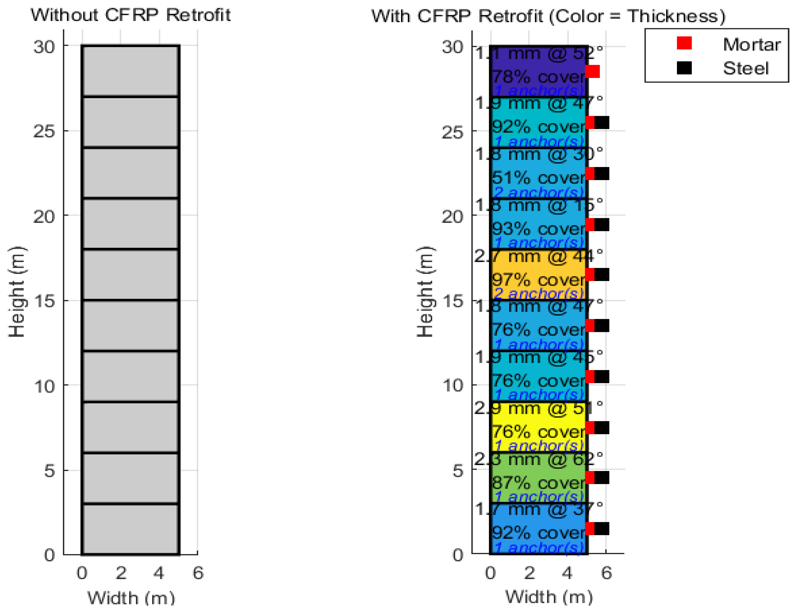
The simulation results collectively demonstrate that the proposed CFRP optimization framework:
- —
- Reduced roof displacement by up to 70%,
- —
- Limited inter-storey drift to <0.0004,
- —
- Enhanced stiffness and reduced inelastic deformation,
- —
- Achieved material- and carbon-efficient designs, and
- —
- Delivered retrofit schemes with practical constructability details.
Thus, the overall results confirm that the proposed NSGA-II driven MOGA optimization algorithms can produce seismically resilient, sustainable, and constructible CFRP retrofit designs. Unlike conventional uniform wrapping approaches, the proposed method delivers performance-based designs that balance safety, cost, and carbon footprint. Such results provide strong evidence for real-world applicability, offering a systematic methodology to guide engineers toward next-generation retrofit strategies.
6. Conclusions
This research paper proposed a robust multi-objective NSGA-II heuristic optimization driven carbon fiber reinforced polymer (CFRP) structure for seismic resilient and sustainable high-rise infrastructure development. More specifically, the proposed method makes use of the non-linear time-history analysis with the modified MOO genetic algorithm that decides different design specifications for the multi-story building construction. With the help of the proposed MOO-GA (modified NGSA-II) optimization method, the proposed framework at first decides whether a floor requires CFRP wrapping, mortar jacketing and steel jacketing or not. In addition, it also decides the CFRP wrapping conditions on each floor, such as the thickness, orientation, design patterns (i.e., unilinear, bidirectional and hybrid), coverage and anchors etc. Noticeably, these objectives are achieved while minimizing CFRP costs (i.e., CFRP, resin, steel and mortar), torsional irregularity index (i.e., per floor drift and torsional surrogate), Park Ang damage index and sensitivity towards seismic loading conditions. It improves not only cost of construction but also reliability, thus enabling safe and high-longevity vertical structure developments. Additionally, the CFRP wrapping is performed while constraining non-structural elements or content that improves reliability of the overall vertical structure under seismic loading conditions. The MATLAB-based simulations inferred that the proposed CFRP wrapping structure can reduce torsional impacts by almost 35%, thus making it more seismic resilient. The research method infers that the hybrid CFRP structure with 20-40 MPa mortar, with the steel jacketing of 10-40 mm (if used) can make CFRP structure more seismic-resilient. It also suggests to implement 0-2 per end per face anchorage to reduce torsional impacts and residual drift (≤ 0.5–1.0%). For a 10-storey building structure, the simulations revealed that for the lower floor including 1-3 floors, if the damage index remains same the mortar and steel jacketing can be applied with the CFRP orientation up to ±45°. On the other hand, for 4-7 floors, hybrid 0/±45° CFRP can be applied which can balance drift as well as torsional instability under seismic loading condition. Though, for the stories 8–10, ±45° dominant CFRP can be applied with the occasional 90° bands near joints to maintain stability and low sensitivity. For the targeted structural design, CFRP thickness can be selected in the range of 0-3 mm, where it can apply 0.-6 plies of ~0.17–0.5 mm/ply. The overall design specifications and mechanical characterizations confirm robustness and seismic resilience of the target structure, which can make civil constructions more reliable and cost-effective.
References
- Cao X-Y. Probabilistic seismic performance evaluation of existing buildings through non-stationary stochastic ground motions and incremental dynamic analysis. Proc 7th Int Conf Hydraulic and Civil Engineering & Smart Water Conservancy and Intelligent Disaster Reduction Forum (ICHCE & SWIDR); 2021; Nanjing, China. p. 1167–70.
- Prasath P, Silambarasan D. An experimental investigation on flexural behaviour of stainless-steel fiber reinforced concrete beam elements. Proc Int Conf Current Trends in Engineering and Technology (ICCTET); 2013; Coimbatore, India. p. 146–51.
- Nie J, Qin K, Xiao V. Push-over analysis of the seismic behavior of a concrete-filled rectangular tubular frame structure. Tsinghua Sci Technol. 2006;11(1):124–30. [CrossRef]
- Cao X-Y. Probabilistic seismic performance evaluation of existing buildings through non-stationary stochastic ground motions and incremental dynamic analysis. Proc 7th Int Conf Hydraulic and Civil Engineering & Smart Water Conservancy and Intelligent Disaster Reduction Forum (ICHCE & SWIDR); 2021; Nanjing, China. p. 1167–70.
- Di Ludovico M, Prota A, Manfredi G, Cosenza E. Seismic strengthening of an under-designed RC structure with FRP. Earthq Eng Struct Dyn. 2008;37(1):141–62. [CrossRef]
- Kosmopoulos AJ, Fardis MN. Estimation of inelastic seismic deformations in asymmetric multistorey RC buildings. Earthq Eng Struct Dyn. 2007;36(9):1209–30. [CrossRef]
- CEN. Eurocode 2: Design of concrete structures—Part 1-1: General rules and rules for buildings. Brussels, Belgium: Comité Européen de Normalization; 2004.
- Chaudat T, Garnier C, Cvejic S, Poupin S, Le Corre M, Mahe M. ECOLEADER Project No. 2: Seismic tests on a reinforced concrete bare frame with FRP retrofitting—Tests report. SEMT/EMSI/RT/05-006/A. Saclay, France: CEA; 2005.
- Palermo A, Tsionis G, Sousa L. Seismic design in Europe post-1980s. Conf Proc; 2018.
- Gkatzogias D, et al. Assessment of existing buildings under seismic loads. Conf Proc; 2022.
- Chiu C, Hsiao Y, Jean J. Cost-effectiveness of seismic retrofitting. Conf Proc; 2013.
- Smyth A, et al. Seismic risk reduction through retrofitting. Conf Proc; 2004.
- European Commission. Renovation Wave. Brussels, Belgium: European Commission; 2020.
- European Commission. EU Green Deal. Brussels, Belgium: European Commission; 2019.
- Bournas T. Integrated seismic and energy retrofitting. Conf Proc; 2018.
- Pohoryles D, et al. Policy and economic perspectives on retrofitting. Conf Proc; 2020.
- Gkournelos P, Triantafillou T, Bournas T. Seismic upgrading techniques for RC buildings. Conf Proc; 2021.
- Bousselham A. FRP retrofitting in seismic applications. Conf Proc; 2010.
- Del Vecchio C, et al. Performance of FRP-retrofitted structures. Conf Proc; 2016.
- Hollaway L. Advances in FRP composites in civil engineering. Conf Proc; 2010.
- Triantafillou T. FRP in structural rehabilitation. Conf Proc; 2001.
- Bournas T, et al. Seismic retrofit of RC columns using FRP wrapping. Conf Proc; 2007.
- Bousias M, Spathis L, Fardis MN. Column confinement and seismic behavior. Conf Proc; 2007.
- Ferreira J, Barros J. Flexural and shear strengthening of RC members. Conf Proc; 2006.
- Sheikh S, Li G. Confinement of RC columns with FRP. Conf Proc; 2007.
- Alsayed S, et al. FRP retrofit of beam-column joints. Conf Proc; 2010.
- Del Vecchio C, et al. Behavior of strengthened beam-column joints. Conf Proc; 2014.
- Pantazopoulou P, et al. Design guidelines for FRP retrofitting of RC structures. Conf Proc; 2016.
- Pohoryles D, et al. Review of FRP seismic retrofitting practices. Conf Proc; 2019.
- Porter K. PEER PBEE methodology. Conf Proc; 2003.
- Yurdakul T, et al. Seismic fragility of FRP-retrofitted structures. Conf Proc; 2023.
- Kappos S, Dimitrakopoulos E. Fragility curves for modern code-compliant RC structures. Conf Proc; 2008.
- Pohoryles D, et al. Seismic performance of modern RC buildings. Conf Proc; 2020.
- Cardone D, Gesualdi G, Perrone M. Modified fragility curves from pushover analysis. Conf Proc; 2019.
- Mastroberti L, et al. Experimental-based fragility assessment. Conf Proc; 2018.
- Wang L-K, Zhou Y, Nagarajaiah S, Shi W-X. Bi-directional semi-active tuned mass damper for torsional asymmetric structural seismic response control. Eng Struct. 2023; 294:116744. [CrossRef]
- Liu Y, Fan L, Wang W, Gao Y, He J. Failure analysis of damaged high-strength bolts under seismic action based on finite element method. Buildings. 2023;13(3):776. [CrossRef]
- Wang L-K, Zhou Y, Nagarajaiah S, Shi W-X. Bi-directional semi-active tuned mass damper for torsional asymmetric structural seismic response control. Eng Struct. 2023; 294:116744. [CrossRef]
- Lee M, Wang W, Wang Y, Hsieh Y, Lin Y. Mechanical properties of high-strength pervious concrete with steel fiber or glass fiber. Buildings. 2022;12(5):620. [CrossRef]
- Wang L-K, Zhou Y, Shi W-X, Zhou Y. Seismic response control of a nonlinear tall building under mainshock–aftershock sequences using semi-active tuned mass damper. Int J Struct Stab Dyn. 2023;23(10):2350106. [CrossRef]
- Federal Emergency Management Agency (FEMA). NEHRP Guidelines for the Seismic Rehabilitation of Buildings, FEMA-273. Washington, DC, USA: Building Seismic Safety Council; 1997.
- Katsumat H, Kobatake Y, Taked T. A study on the strengthening with carbon fiber for earthquake-resistant capacity of existing reinforced concrete columns. In: Proc. 9th World Conf. Earthquake Eng. (9WCEE); Tokyo-Kyoto, Japan; 1988. p. 518–522.
- Saadatmanesh H, Ehsani MR, Jin L. Seismic retrofitting of rectangular bridge columns with composite straps. Earthq Spectra. 1997;13(2):281–304. [CrossRef]
- Ye LP, Zhang K, Zhao SH, Feng P. Experimental study on seismic strengthening of RC columns with wrapped CFRP sheets. Constr Build Mater. 2003;17(6–7):499–506. [CrossRef]
- Richelle GA, Kawashima K. Analysis of carbon fiber sheet-retrofitted RC bridge columns under lateral cyclic loading. J Earthq Eng. 2009;13(1):129–154.
- Ghobarah A, Said A. Shear strengthening of beam-column joints. Eng Struct. 2002;24(7):881–888. [CrossRef]
- Wang LK, Nagarajaiah S, Zhou Y, Shi WX. Experimental study on adaptive-passive tuned mass damper with variable stiffness for vertical human-induced vibration control. Eng Struct. 2023; 280:115714. [CrossRef]
- Wang LK, Nagarajaiah S, Shi WX, Zhou Y. Seismic performance improvement of base-isolated structures using a semi-active tuned mass damper. Eng Struct. 2022; 271:114963. [CrossRef]
- Antonopoulos CP, Triantafillou TC. Experimental investigation of FRP-strengthened RC beam-column joints. J Compos Constr. 2003;7(1):39–49. [CrossRef]
- Duong KV, Sheikh SA, Vecchio FJ. Seismic behavior of shear-critical reinforced concrete frame: Experimental investigation. ACI Struct J. 2007;104(3):304–313. [CrossRef]
- El-Sokkary H, Galal K. Analytical investigation of the seismic performance of RC frames rehabilitated using different rehabilitation techniques. Eng Struct. 2009;31(8):1955–1966. [CrossRef]
- Shaikh ZK, Sohoni VS. Performance of carbon fiber-reinforced polymer (CFRP)-strengthened RC frame. Asian J Civ Eng. 2023; 24:1831–1840. [CrossRef]
- Ali O, Bigaud D, Riahi H. Seismic performance of reinforced concrete frame structures strengthened with FRP laminates using a reliability-based advanced approach. Compos Part B Eng. 2018; 139:238–248. [CrossRef]
- Rousakis TC, Saridaki ME, Mavrothalassitou SA, Hui D. Utilization of hybrid approach towards advanced database of concrete beams strengthened in shear with FRPs. Compos Part B Eng. 2015; 85:315–335. [CrossRef]
- Rousakis TC, Anagnostou E, Fanaradelli TD. Advanced composite retrofit of RC columns and frames with prior damages: Pseudo-dynamic finite element analyses and design approaches. Fibers. 2021; 9:56. [CrossRef]
- Fanaradelli TD, Rousakis TC, Karabinis A. Reinforced concrete columns of square and rectangular section, confined with FRP—Prediction of stress and strain at failure. Compos Part B Eng. 2019; 174:107046. [CrossRef]
- Fanaradelli TD, Rousakis TC. 3D finite element pseudo dynamic analysis of deficient rectangular columns confined with fiber reinforced polymers under axial compression. Polymers. 2020; 12:2546. [CrossRef]
- Fanaradelli TD, Rousakis TC. Prediction of ultimate strain for rectangular reinforced concrete columns confined with fiber reinforced polymers under cyclic axial compression. Polymers. 2020; 12:2691. [CrossRef]
- Anagnostou E, Rousakis TC. Performance of steel bar lap splices at the base of seismic resistant reinforced concrete columns retrofitted with FRPs—3D finite element analysis. Fibers. 2022; 10:107. [CrossRef]
- Garcia R, Hajirasouliha I, Pilakoutas K. Seismic behaviour of deficient RC frames strengthened with CFRP composites. Eng Struct. 2010; 32:3075–3085. [CrossRef]
- Wattanapanich C, Imjai T, Garcia R, Rahim NL, Abdullah MMA, Sandu AV, Vizureanu P, Matasaru PD, Thomas BS. Computer simulations of end-tapering anchorages of EBR FRP-strengthened prestressed concrete slabs at service conditions. Materials. 2023; 16:851. [CrossRef]
- Muslum MM, Fatih K. Structural performance of reinforced concrete (RC) moment frame connections strengthened using FRP composite jackets. Arab J Sci Eng. 2021; 46:10975–10992.
- Attari N, Youcef YS, Amziane S. Seismic performance of reinforced concrete beam–column joint strengthening by FRP sheets. Structures. 2019; 20:353–364. [CrossRef]
- Imjai T, Garcia R, Guadagnini M, Pilakoutas K. Strength degradation in curved fiber-reinforced polymer (FRP) bars used as concrete reinforcement. Polymers. 2020; 12:1653. [CrossRef]
- Hanan AN, Muneer N. Confinement effects of unidirectional CFRP sheets on axial and bending capacities of square RC columns. Eng Struct. 2019; 196:109329.
- Imjai T, Guadagnini M, Pilakoutas K. Curved FRP as concrete reinforcement. Proc Inst Civ Eng. 2009; 162:171–178. [CrossRef]
- Yang J, Liang ST, Zhu XJ, Dang LJ, Wang JL, Tao JX. Experimental research and finite element analysis on the seismic behavior of CFRP-strengthened severely seismic-damaged RC columns. Structures. 2021; 34:3968–3981. [CrossRef]
- Eslami A, Ronagh HR. Experimental investigation of an appropriate anchorage system for flange bonded carbon fiber–reinforced polymers in retrofitted RC beam–column joints. J Compos Constr. 2013; 18:04013056. [CrossRef]
- Ronagh HR, Eslami A. Flexural retrofitting of RC buildings using GFRP/CFRP—A comparative study. Compos Part B Eng. 2013; 46:188–196. [CrossRef]
- Eslami A, Ronagh HR, Mostofinejad D. Analytical assessment of CFRP retrofitted reinforced-concrete buildings subjected to near-fault ground motions. J Perform Constr Facil. 2016; 30:04016044. [CrossRef]
- Di Ludovico M, Prota A, Manfredi G, Cosenza E. Seismic strengthening of an under-designed RC structure with FRP. Earthq Eng Struct Dyn. 2008; 37:141–162. [CrossRef]
- Balsamo A, Colombo A, Manfredi G, Negro P, Prota A. Seismic behavior of a full-scale RC frame repaired using CFRP laminates. Eng Struct. 2005; 27:769–780. [CrossRef]
- Valente M, Milani G. Alternative retrofitting strategies to prevent the failure of an under-designed reinforced concrete frame. Eng Fail Anal. 2018; 89:271–285. [CrossRef]
- Valente M. Seismic upgrading strategies for non-ductile plan-wise irregular R/C structures. Procedia Eng. 2013; 54:539–553. [CrossRef]
- Wang N, Ellingwood BR, Zureick A-H. Reliability-based evaluation of flexural members strengthened with externally bonded fiber-reinforced polymer composites. J Struct Eng. 2010; 136:1151–1160. [CrossRef]
- Plevris N, Triantafillou TC, Veneziano D. Reliability of RC members strengthened with CFRP laminates. J Struct Eng. 1995; 121:1037–1044. [CrossRef]
- Wieghaus KT, Atadero RA. Effect of existing structure and FRP uncertainties on the reliability of FRP-based repair. J Compos Constr. 2010; 15:635–643. [CrossRef]
- Huang X, Sui L, Xing F, Zhou Y, Wu Y. Reliability assessment for flexural FRP-strengthened reinforced concrete beams based on importance sampling. Compos Part B Eng. 2019; 156:378–398. [CrossRef]
- Zou Y, Hong HP. Reliability assessment of FRP-confined concrete columns designed for buildings. Struct Infrastruct Eng. 2011; 7:243–258. [CrossRef]
- Ali O. Structural reliability of biaxial loaded short/slender-square FRP-confined RC columns. Constr Build Mater. 2017; 151:370–382. [CrossRef]
- Baji H, Ronagh HR, Li C-Q. Probabilistic assessment of FRP-confined reinforced concrete columns. Compos Struct. 2016; 153:851–865. [CrossRef]
- Zou X, Wang Q, Wu J. Reliability-based performance design optimization for seismic retrofit of reinforced concrete buildings with fiber-reinforced polymer composites. Adv Struct Eng. 2018; 21:838–851. [CrossRef]
- Ali O, Bigaud D, Riahi H. Seismic performance of reinforced concrete frame structures strengthened with FRP laminates using a reliability-based advanced approach. Compos Part B Eng. 2018; 139:238–248. [CrossRef]
- Bureau of Indian Standards. IS 15988: Seismic evaluation and strengthening of existing reinforced concrete buildings—Guidelines. New Delhi, India: BIS; 2013.
- Garcia R, Hajirasouliha I, Pilakoutas K. Seismic behaviour of deficient RC frames strengthened with CFRP composites. Eng Struct. 2010;32(10):3075–3085. [CrossRef]
- Mohammed AAO. Shear behaviour of RC beams retrofitted using UHPFRC panels epoxied to the sides. Comput Concr. 2019;21(1):37–49.
- Meraji L, Afshin H, Abedi K. Flexural behavior of RC beams retrofitted by ultra-high-performance fiber-reinforced concrete. Comput Concr. 2019;24(2):159–172.
- Sengupta AK, Reddy CS, Narayanan VTB, Asokan A. Seismic analysis and retrofit of existing multi-storied buildings in India—An overview with a case study. In: Proc. 13th World Conf. Earthquake Eng.; Vancouver, Canada; Aug. 2004.
- Gunay MS, Sucuoğlu H. A comparative evaluation of performance-based seismic assessment procedures. In: Proc. 13th World Conf. Earthquake Eng.; Vancouver, Canada; Aug. 2004.
- Fajfar P, Fischinger M. N2—A method for non-linear seismic analysis of regular buildings. In: Proc. 9th World Conf. Earthquake Eng.; Tokyo-Kyoto, Japan; Aug. 1988.
- Vielma JC, Martinez Y, Barbat AH, Oller S. The Quadrants Method: A procedure to evaluate the seismic performance of existing buildings. In: Proc. 15th World Conf. Earthquake Eng.; Lisbon, Portugal; Sep. 2012.
- Mohamed S, Yasser EI, Mohamed E. Seismic retrofitting of a deteriorated RC building. Case Stud Constr Mater. 2023; 18:1–12.
- Lee SJ, Lee DH, Kim KS, Oh JY, Park MK, Yang IS. Seismic performances of RC columns reinforced with screw ribbed reinforcements connected by mechanical splice. Comput Concr. 2013;12(2):131–149. [CrossRef]
- Jafarzadeh H, Nematzadeh M. Flexural strengthening of fire-damaged GFRP-reinforced concrete beams using CFRP sheet: Experimental and analytical study. Compos Struct. 2022; 288:115378. [CrossRef]
- Mumtaz Y, Nasiri A, Tetsuhiro S. A comparative study on retrofitting concrete column by FRP-wrapping and RC-jacketing methods: A feasibility study for Afghanistan. Indian J Sci Technol. 2021;14(7):652–664. [CrossRef]
- Cosgun T, Sayin B, Gunes B, Mangir A. Retrofitting technique effectiveness and seismic performance of multi-rise RC buildings: A case study. Case Stud Constr Mater. 2022;16:e00931. [CrossRef]
- Antoniou S. Seismic Retrofit of Existing Reinforced Concrete Buildings. Hoboken, NJ, USA: John Wiley & Sons; 2023.
- Arslan MH, Yazman Ş, Hamad AA, Aksoylu C, Özkılıç YO, Gemi L. Shear strengthening of reinforced concrete T-beams with anchored and non-anchored CFRP fabrics. Structures. 2022; 39:527–542. [CrossRef]
- Vats A, Singh AK, Singh MA. Seismic analysis and retrofitting of reinforced concrete building in Indian seismic zone V. Int Res J Eng Technol. 2019;6(6):3442–3453.
- Granata MF. Seismic retrofit of concrete buildings damaged by corrosion: A case study in southern Italy. Buildings. 2024;14(4):1064. [CrossRef]
- Bhusal B, Pradhananga A, Paudel S, Najam FA. Evaluating and strengthening low-rise reinforced concrete buildings constructed in Nepal. Structures. 2024; 63:106388. [CrossRef]
- DeBock DJ, et al. Quantitative assessment of seismic design provisions for buildings with torsional irregularities. Earthquake Spectra. 2021;37(2):XXX–XXX. [CrossRef]
- Akyürek M. Lateral and Torsional Seismic Vibration Control for Torsionally Irregular Buildings [Ph.D. dissertation]. Melbourne, FL, USA: Florida Inst. Technol.; 2019.
- Italian National Research Council. CNR-DT 200: Instructions for Design, Execution, and Control of Strengthening Interventions Through Fiber-Reinforced Composites. Rome, Italy; 2013.
- European Committee for Standardization. Eurocode 8: Design of Structures for Earthquake Resistance—Part 3: Assessment and Retrofitting of Buildings. Brussels, Belgium; 2005.
- Biskinis DE, Roupakias GK, Fardis MN. Degradation of shear strength of reinforced concrete members with inelastic cyclic displacements. ACI Struct J. 2004;101(6):773–783.
- Di Trapani F, Bertagnoli G, Ferrotto MF, Gino D. Empirical equations for the direct definition of stress–strain laws for fiber-section based macro-modeling of infilled frames. J Eng Mech. 2018;144(11):04018101. [CrossRef]
- Van Thai M, Galimard P, Elachachi S, Ménard S. Multi-objective optimization of cross laminated timber-concrete composite floor using NSGA-II. J Build Eng. 2022; 52:104285. [CrossRef]
- Leyva H, Bojórquez J, Bojórquez E, Reyes-Salazar A, López-Almansa F. Multi-objective seismic design of BRBs-reinforced concrete buildings using genetic algorithms. Struct Multidiscip Optim. 2021; 64:2097–2112. [CrossRef]
- Tu X, He Z, Huang G. Seismic multi-objective of vertically irregular steel frames with setbacks upgraded by buckling-restrained braces. Structures. 2022; 39:470–481. [CrossRef]
- Vukadinović A, Radosavljević J, Protić M, Petrović N. Multi-objective optimization of energy performance for a detached residential building with a sunspace using the NSGA-II genetic algorithm. Sol Energy. 2021; 224:1426–1444. [CrossRef]
Figure 2.
MOGA optimization algorithm.
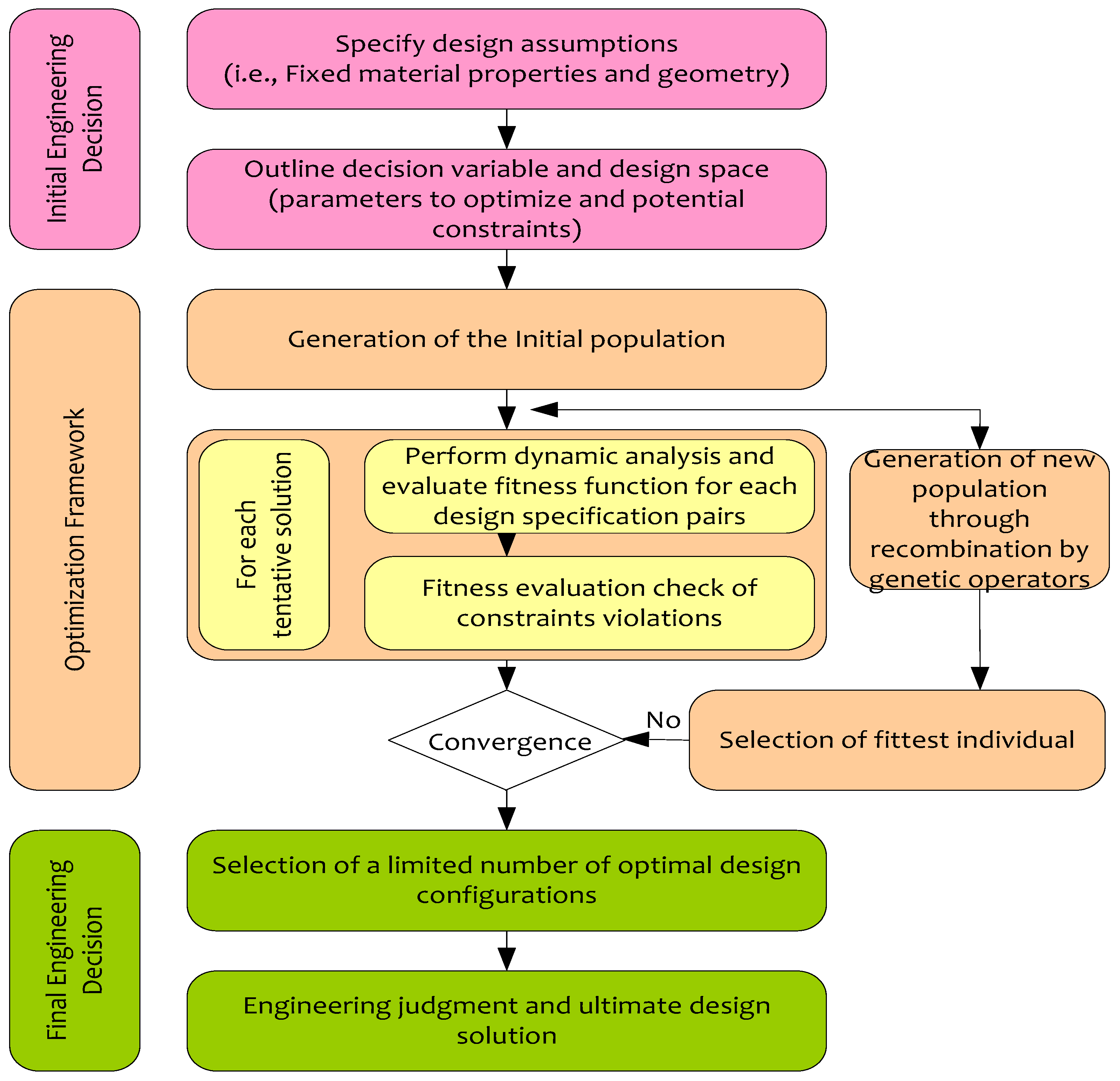
Figure 3.
GA algorithm routine.
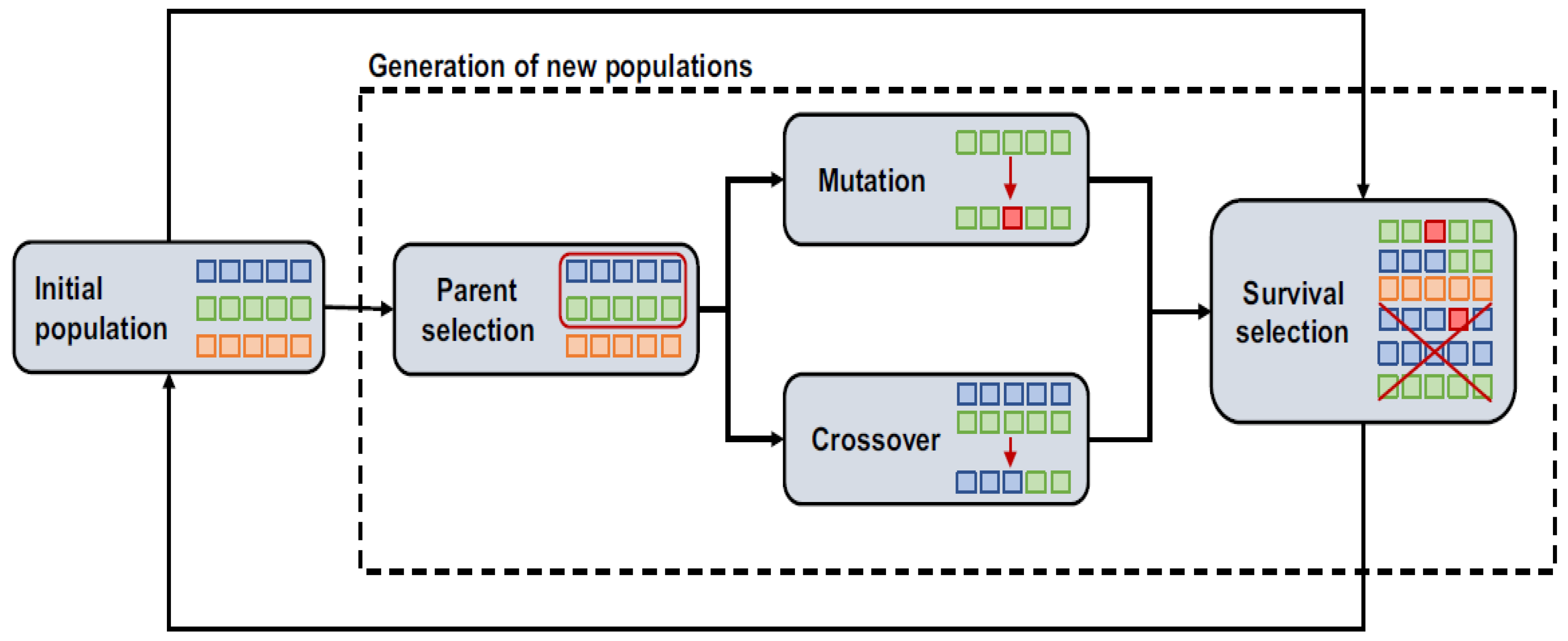
Figure 4.
Seismic damage under uncertainty.
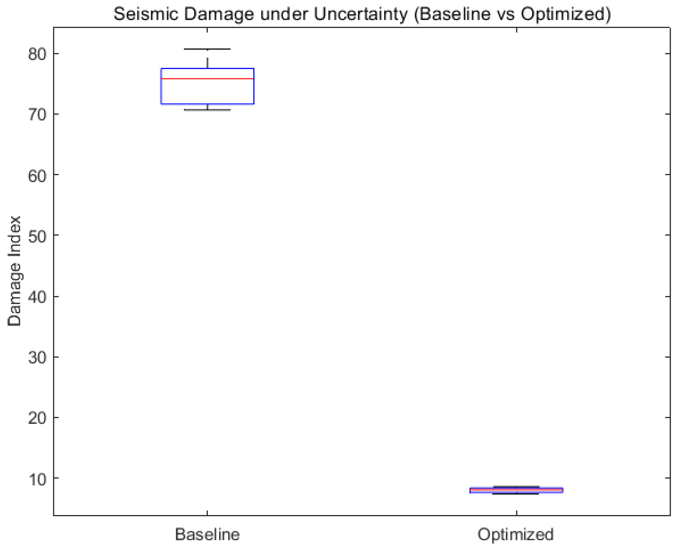
Figure 5.
(a-c): Optimized distribution of CFRP retrofitting parameters over the different stories.
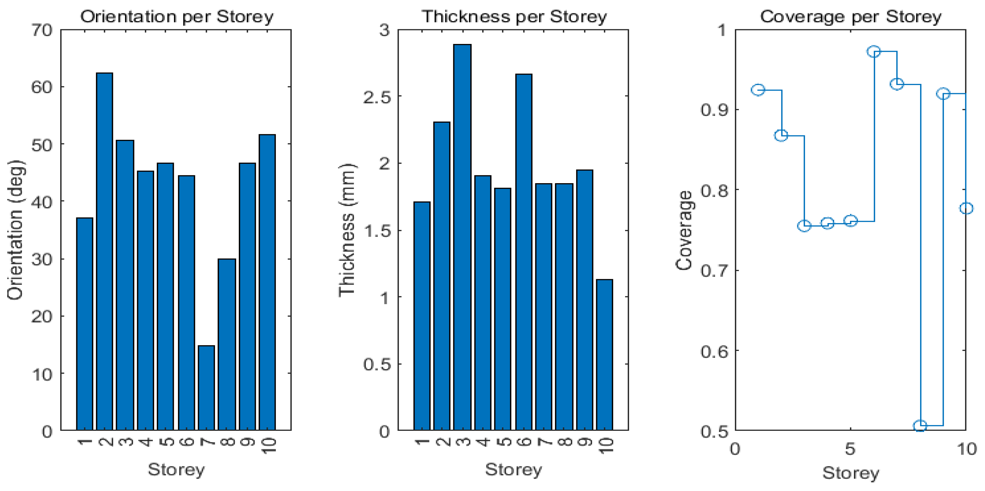
Figure 6.
Pareto analysis of damage vs cost factor.
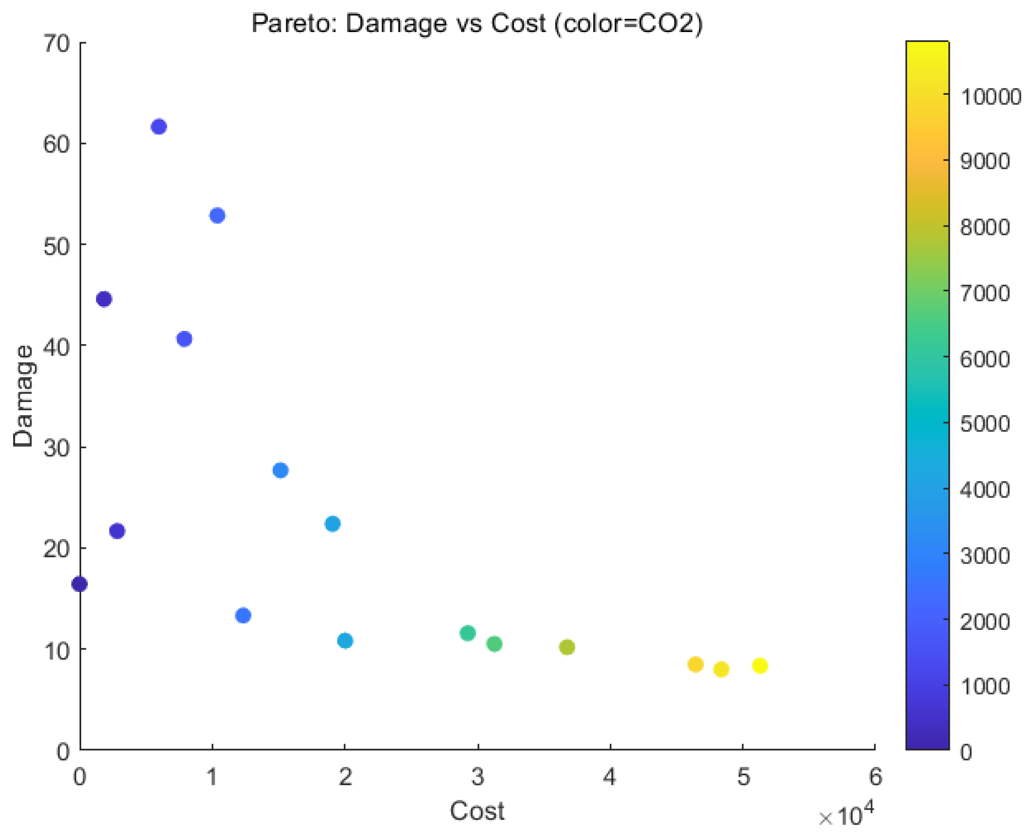
Figure 7.
Damage Index under different retrofitting conditions.
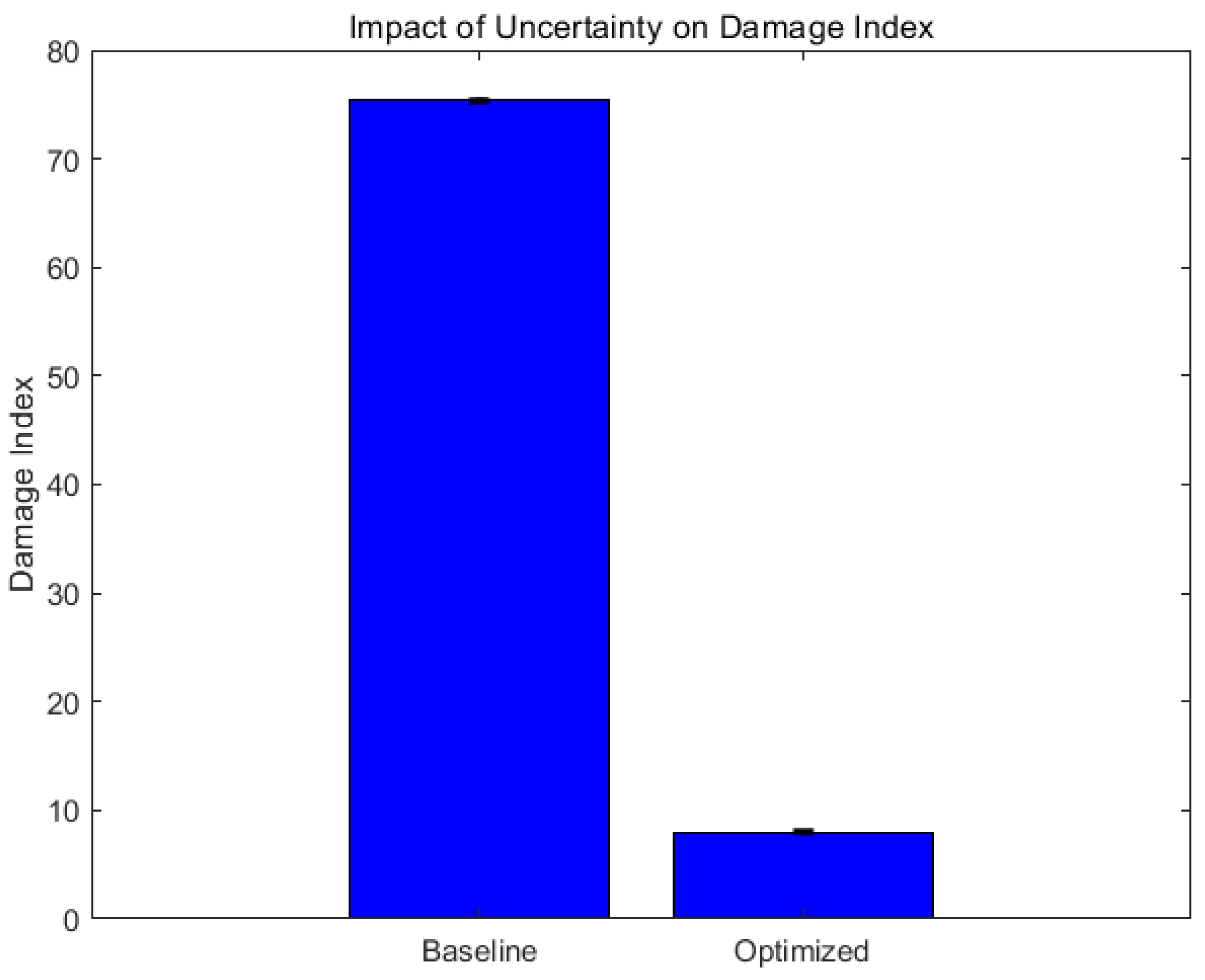
Figure 8.
Average CFRP thickness Vs damage index.
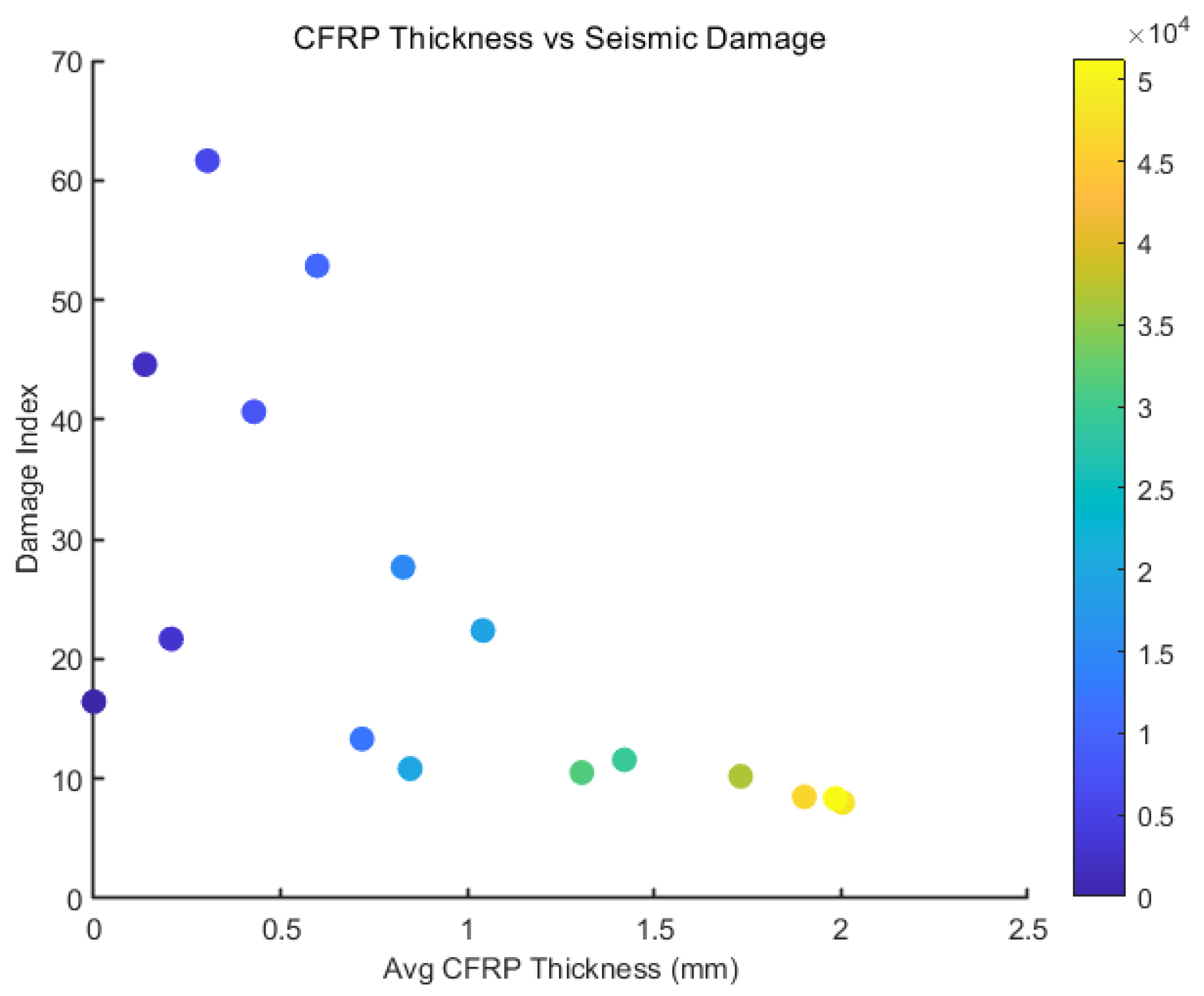
Figure 9.
Retrofit cost Vs Damage index.
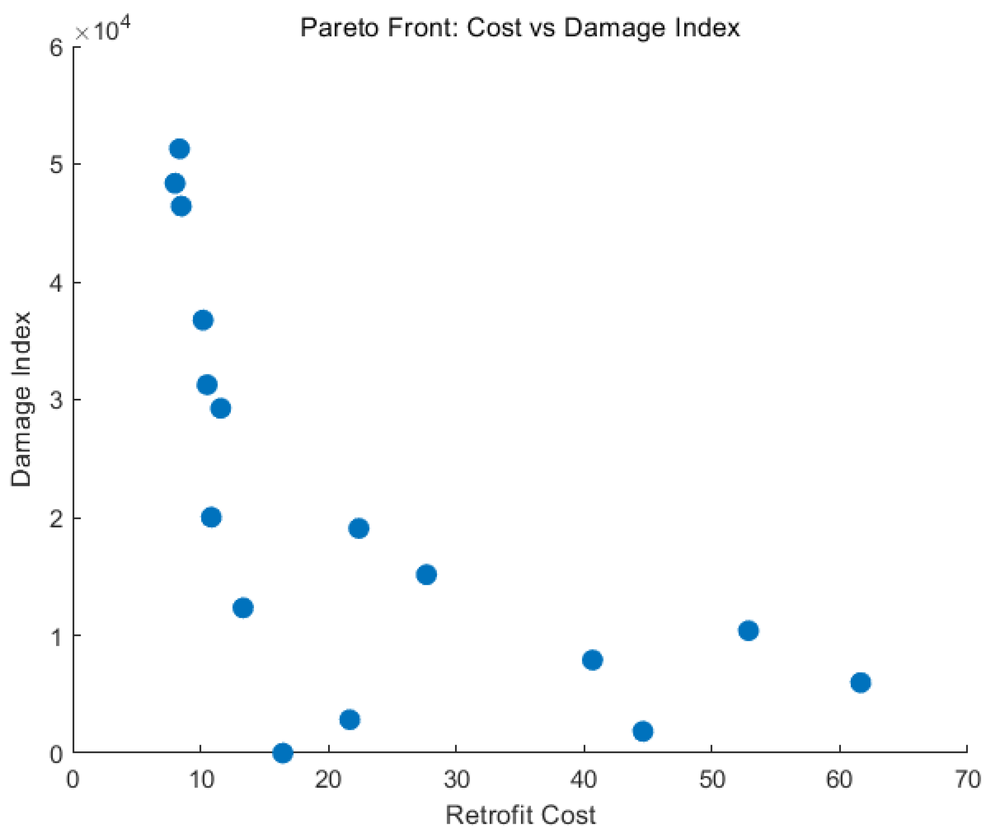
Figure 10.
Damage index under uncertainty with the different retrofitting conditions.
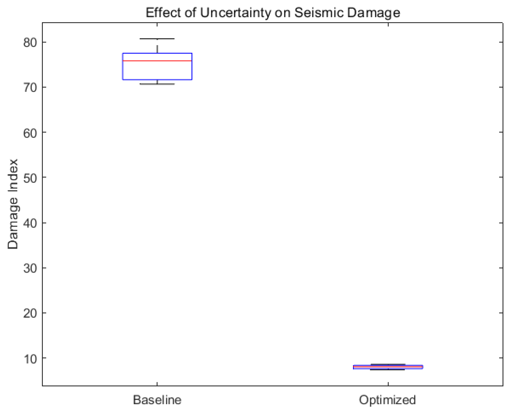
Figure 11.
Pareto-optimal trade-off solutions between retrofit cost and embodied carbon.
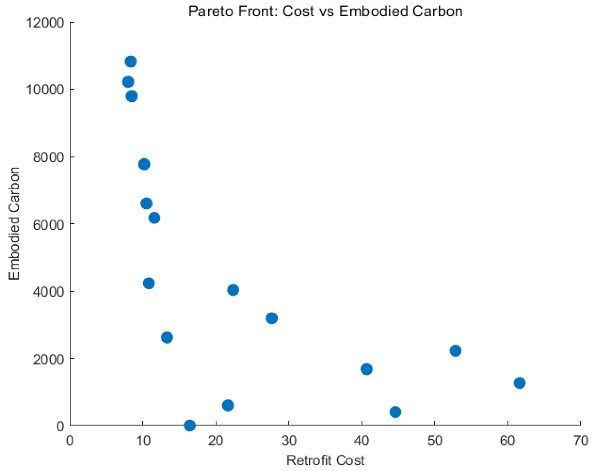
Figure 12.
Pareto-optimal solutions depicting tortional irregularity index vs damage index.
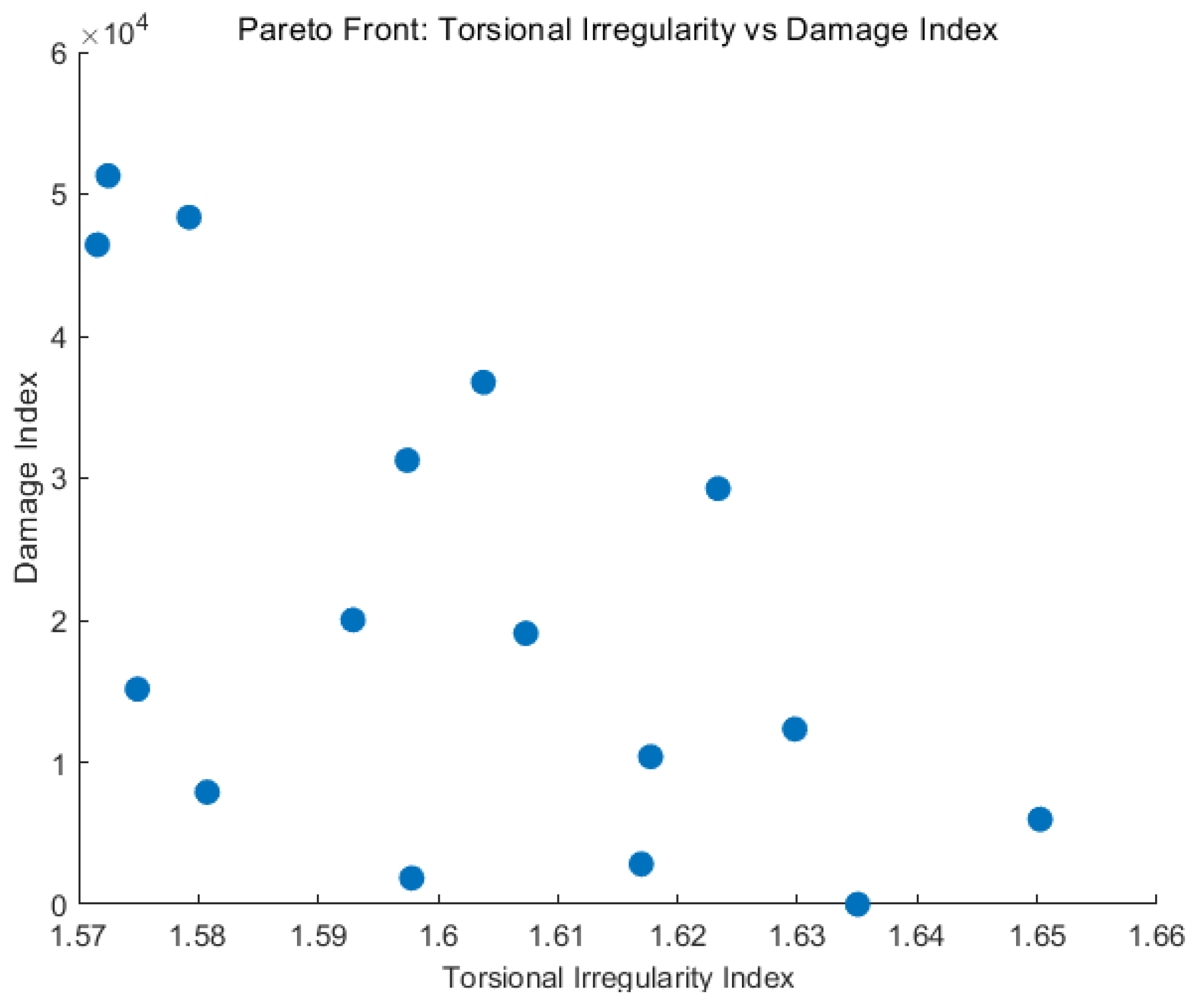
Figure 13.
Displacement response of the 10-storey building under seismic excitation.
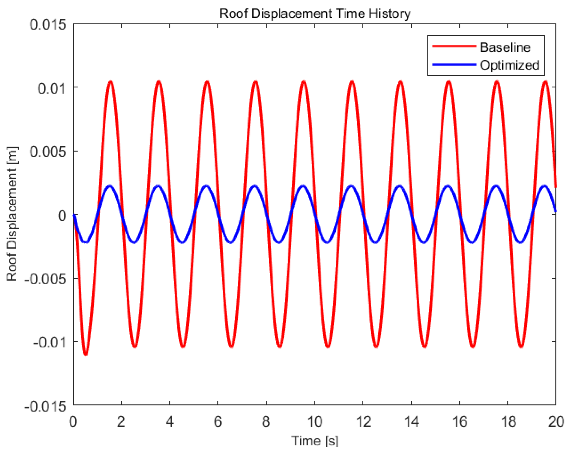
Figure 14.
Comparison of the inter-storey drift ratios for the baseline and optimized retrofitting cases.
Figure 14.
Comparison of the inter-storey drift ratios for the baseline and optimized retrofitting cases.
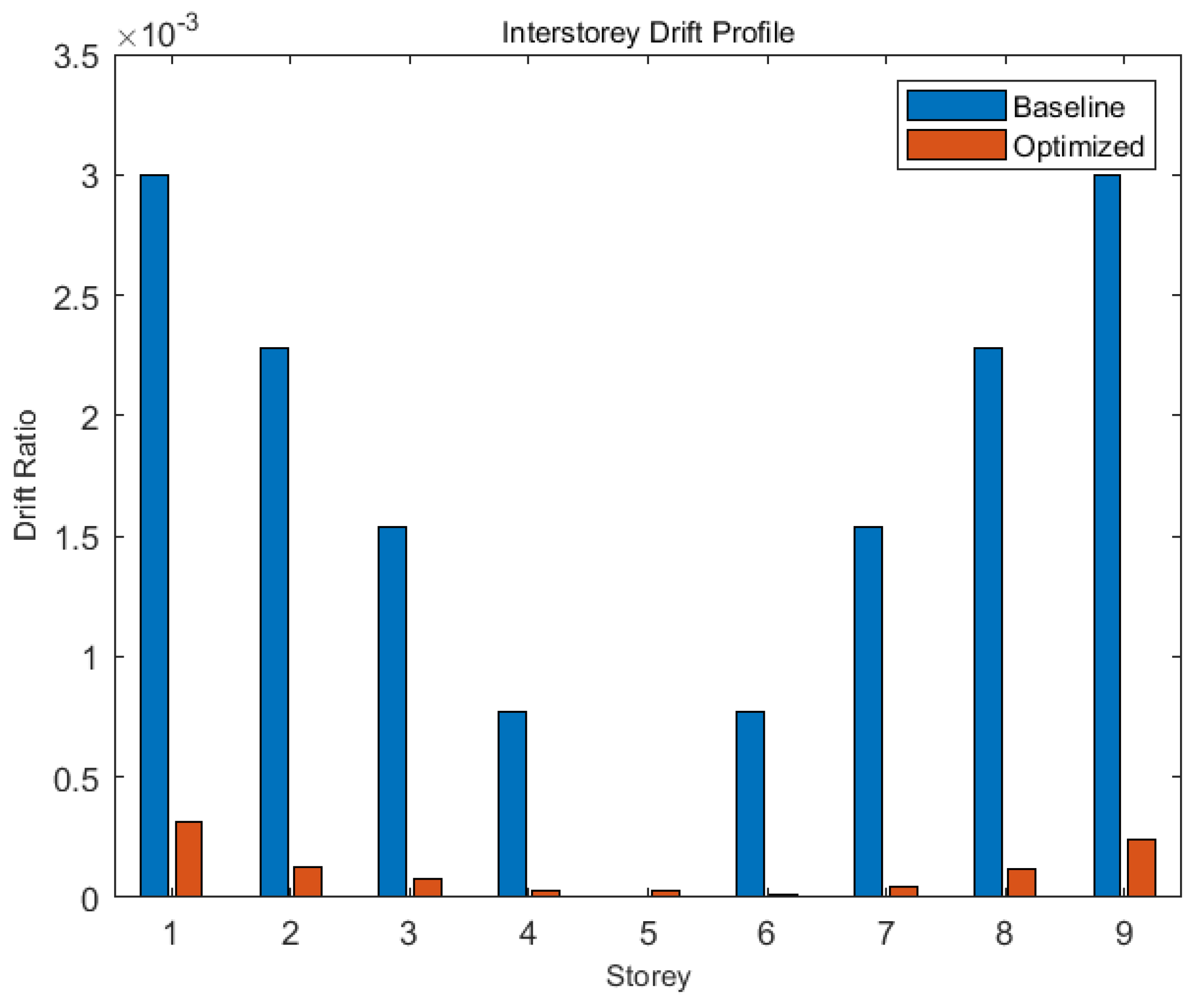
Figure 15.
Roof displacement vs shear under baseline and optimized retrofitting cases.
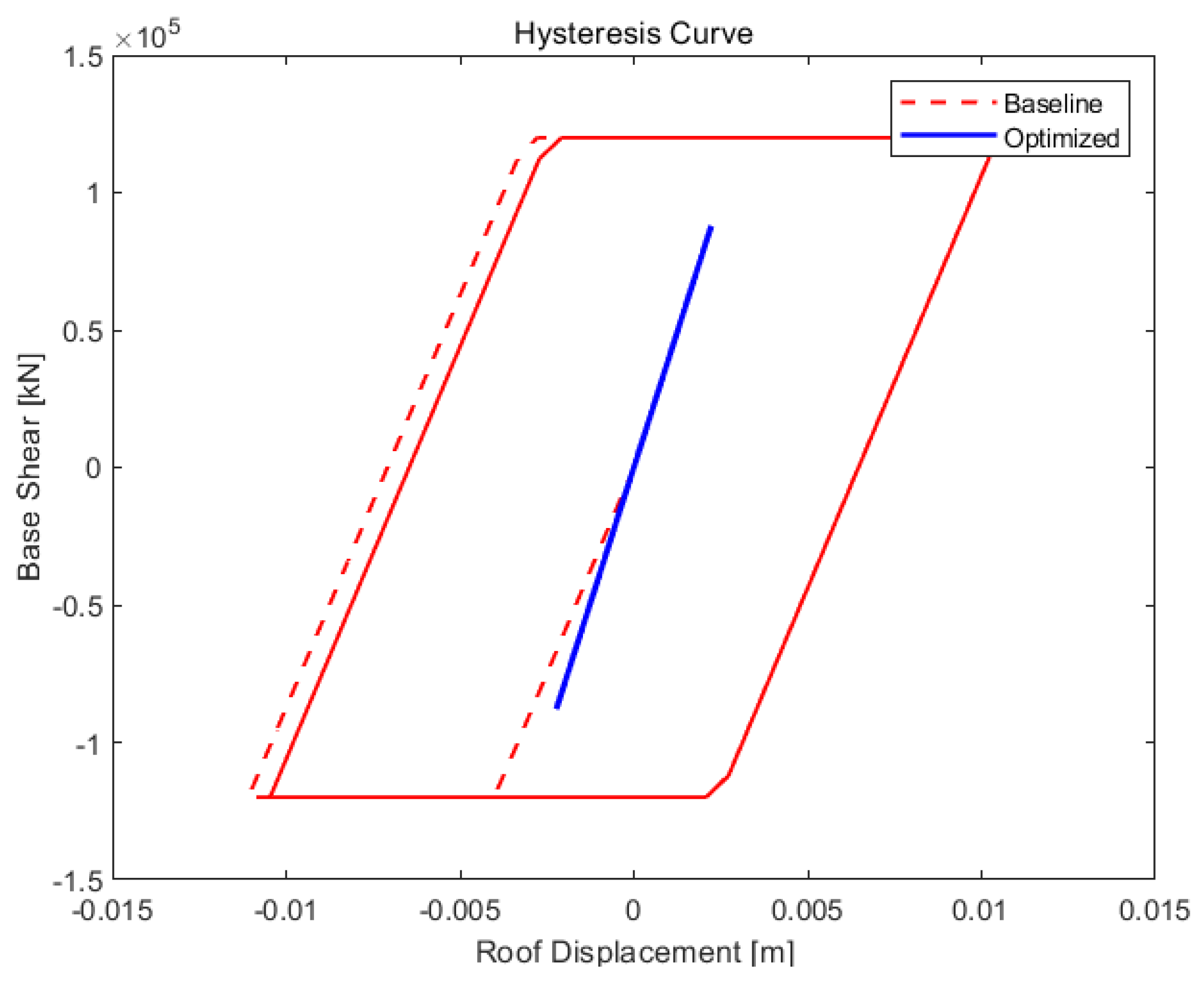
Figure 16.
Variation in CFRP laminate thickness across the ten storeys.
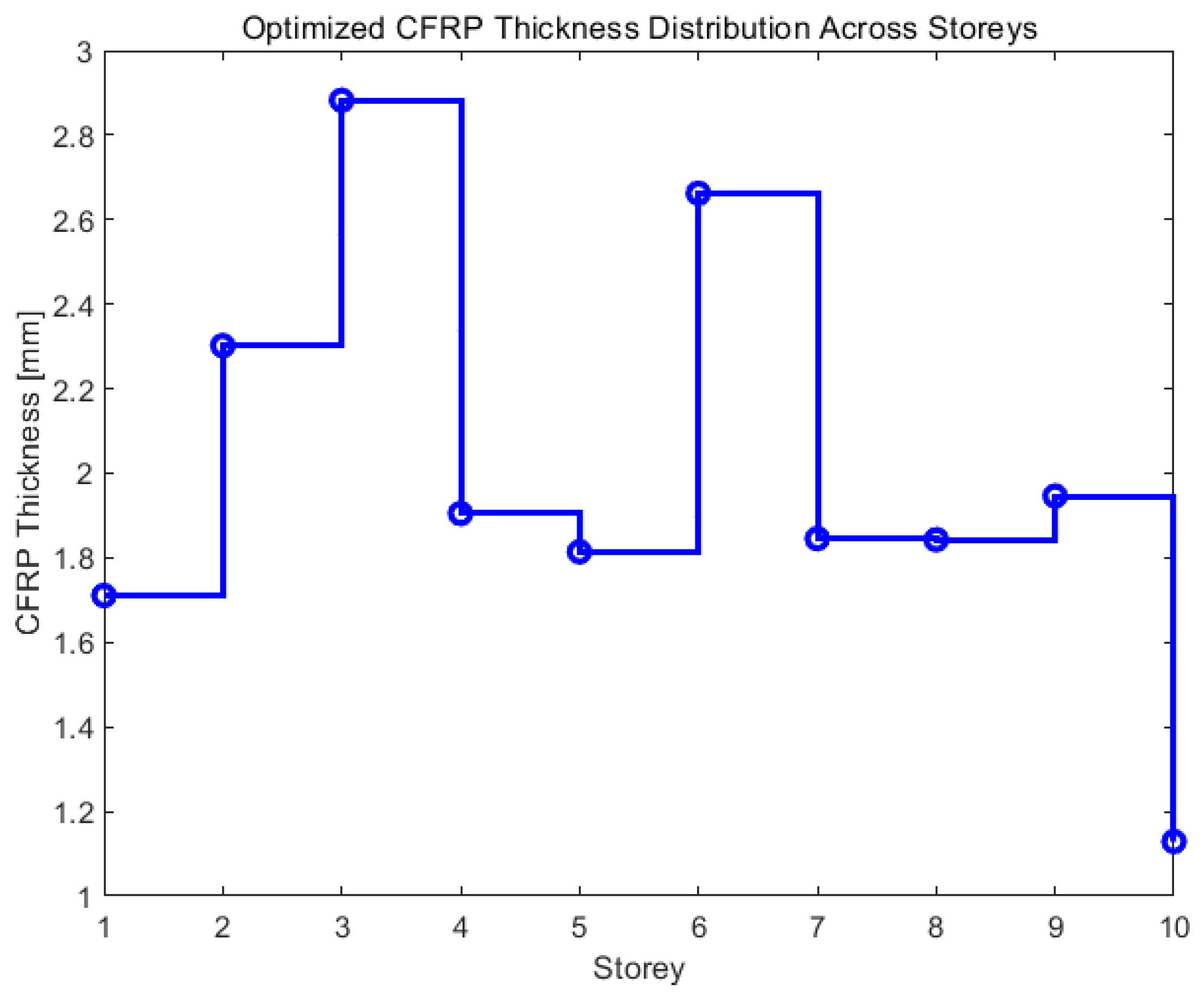
Figure 17.
Embodied carbon vs damage index.
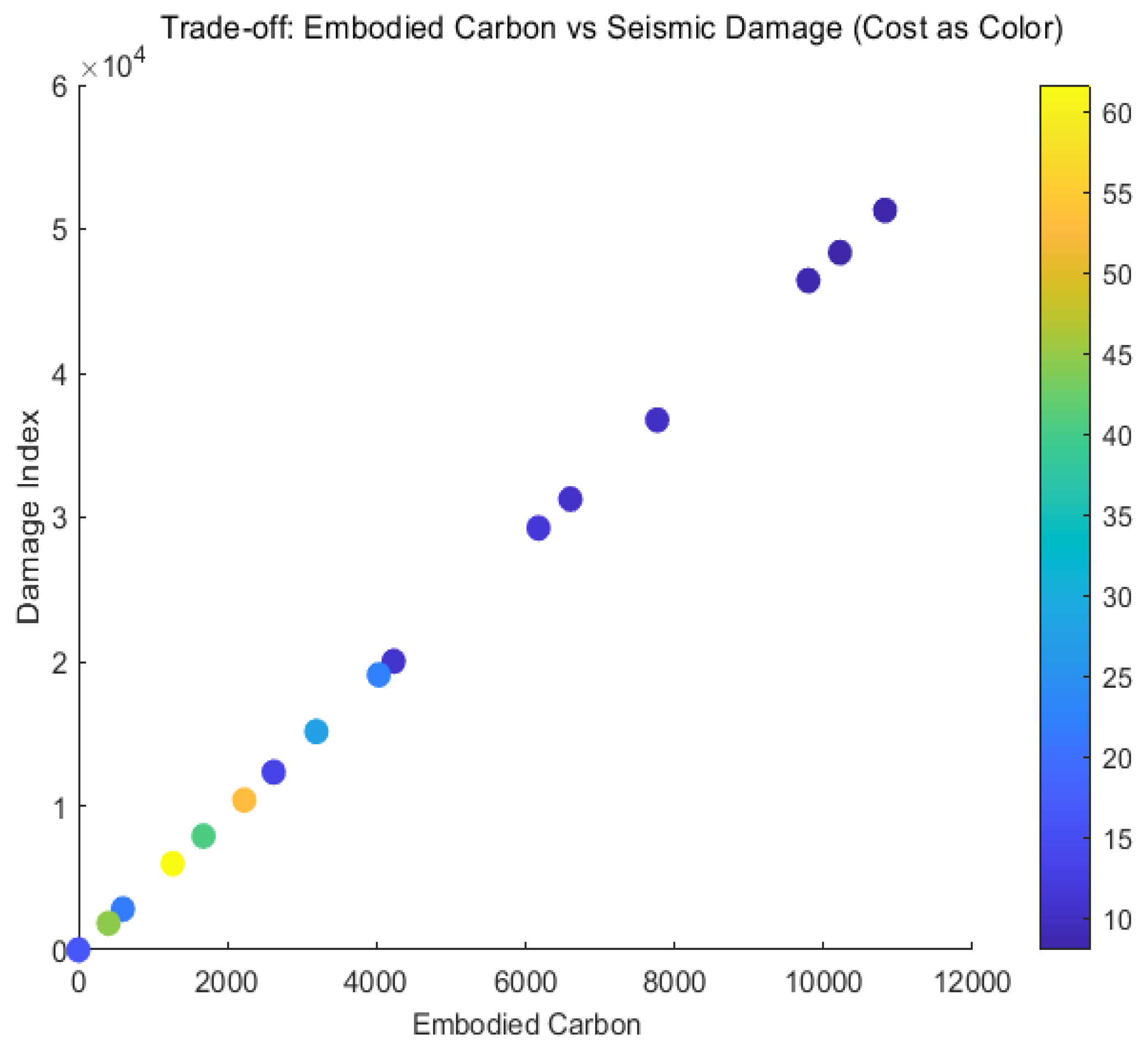
Figure 18.
Baseline vs retrofitting model.
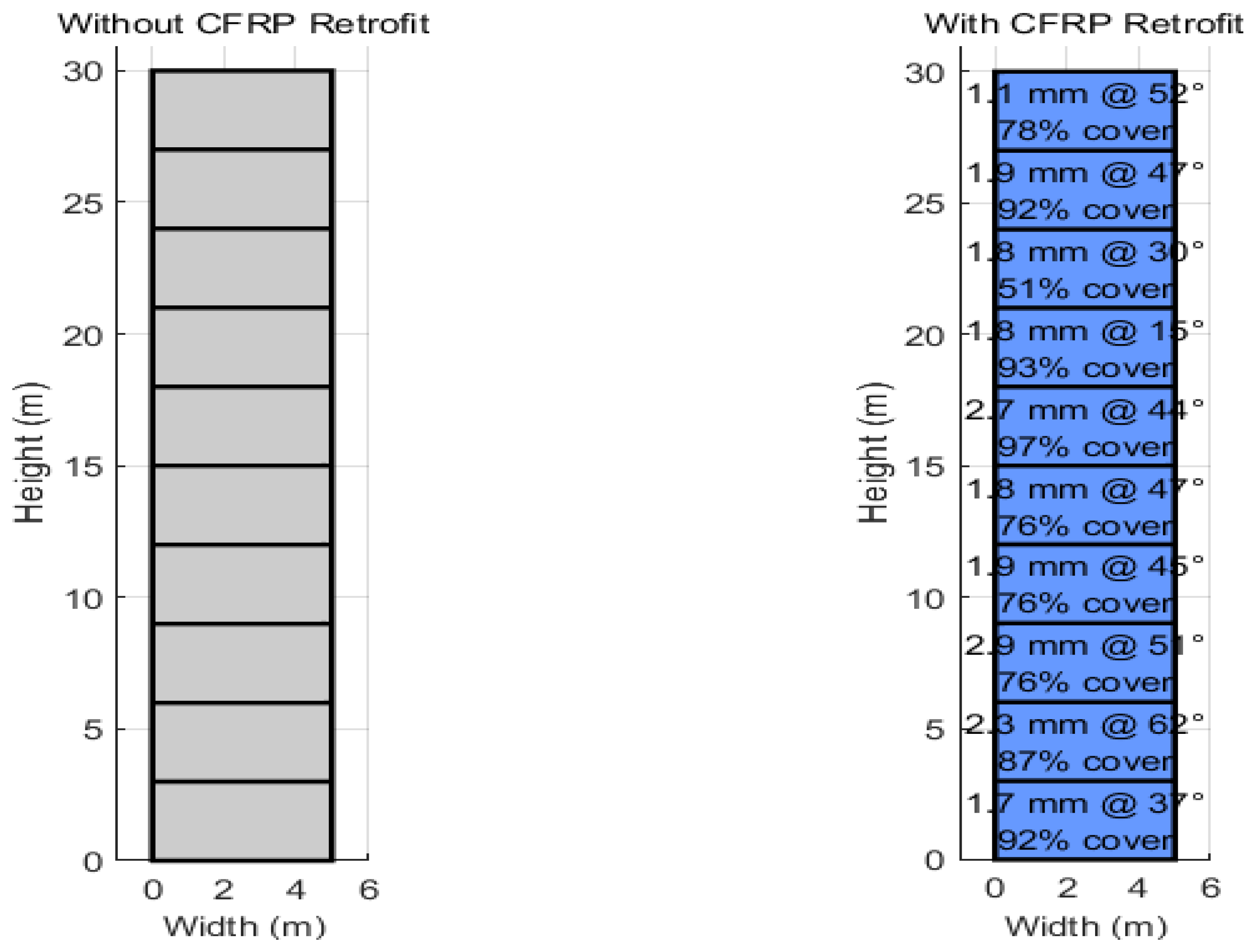
Table 2.
CFRP Design Specifications.
| Parameter | Specification |
|---|---|
| Material Type | Unidirectional, Bidirectional, or Hybrid CFRP |
| Thickness | 0.5 mm to 5 mm |
| Story Wrapping Configuration | Binary array per story |
| Orientation | 0° to 90° (affects stiffness and strength contribution) |
| Thermal Degradation | Modelled using a linear reduction factor based on a reference temperature |
Disclaimer/Publisher’s Note: The statements, opinions and data contained in all publications are solely those of the individual author(s) and contributor(s) and not of MDPI and/or the editor(s). MDPI and/or the editor(s) disclaim responsibility for any injury to people or property resulting from any ideas, methods, instructions or products referred to in the content. |
© 2026 by the authors. Licensee MDPI, Basel, Switzerland. This article is an open access article distributed under the terms and conditions of the Creative Commons Attribution (CC BY) license (http://creativecommons.org/licenses/by/4.0/).
Copyright: This open access article is published under a Creative Commons CC BY 4.0 license, which permit the free download, distribution, and reuse, provided that the author and preprint are cited in any reuse.


