Submitted:
10 February 2026
Posted:
12 February 2026
You are already at the latest version
Abstract
Years of empirical research and technical effort have brought the world into an era defined by modern engineering amenities. The Brushless Direct Current or BLDC motor for electric propulsion systems stands as a significant innovation within this modern period. These motor drives are currently utilized across various sectors including automation systems and electric vehicles along with robotics and industrial applications. While popular control methods like fuzzy logic or PWM offer distinctive functionalities they often struggle with the nonlinear behavior and load variations inherent in BLDC motors. High speed configurations and parametric varieties further complicate stability. To enhance performance a rugged and quickly adaptable controller is required to minimize ripples and improve response times. This study proposes an adaptive PID controller that combines the strengths of a PID autotuner with a standard PID framework. The autotuner provides self adjusting parameters to handle nonlinearities and speed variations through a frequency response estimation process while the fast responsive PID controller compensates for the slow performance of the autotuning phase. These elements work in tandem to automatically readjust parameters for superior accuracy. Using the MATLAB simulation platform a benchmark motor system was developed to verify these results. The proposed design was compared against traditional PID and FPA speed controllers. Results demonstrate that the adaptive PID controller achieves less ripple and an overshoot of less than one percent while maintaining excellent load performance. This research contributes a reliable and highly adaptable control solution for modern BLDC motor systems. Benchmark results in MATLAB Simulink confirm that the proposed controller maintains an overshoot threshold of less than 1% and consistently yields lower torque ripple than existing PID and FPA models.
Keywords:
PID controller
; electric vehicles
; adaptive PID
; BLDC
; PMW
; fuzzy logic
1. Introduction
The modern era marks a profound shift in how we walk with the earth, a cycle set in motion by the birth of the motor. At the same time as we recognize the changing of the seasons, it is classifying these mechanical spirits into two primary lineages: AC and DC motors. While DC motors inhabit many corners of our daily lives, the industrial world primarily looks to two specific forms. In the first, the electrical life force generates magnetic flux through a coiled field; in the second, the flux is provided by the enduring nature of a permanent magnet, a steady heart that does not require the complex wiring of the field poles. Among these, the Brushless DC (BLDC) motor stands out as a synchronous force, defined by its trapezoidal back EMF waveform. By removing the physical friction of brushes and embracing electronic commutation, the BLDC motor achieves a more fluid and efficient path. Current revelations show that this technology has become the heartbeat of global industrial systems and electric vehicle (EV) systems [1,2,3]. In the realm of electric vehicles, where we seek to travel across the land without the heavy breath of combustion, the BLDC motor offers the high performance and reliability necessary to honor the journey. However, directing this energy is a complex ceremony [4,5,6,7]. Operating a BLDC drive requires meticulous observation, structural control, reproduction, and the constant adjustment of parameters. To master the speed of these motors, especially within the demanding environment of a modern drivetrain different control systems have been proposed. The adaptive PID (adaptive proportional-integral-derivative) controller is often chosen because it is quick, simple to modify, and possesses a high, unwavering quality. Still, the traditional path of tuning is fraught with difficulties. The wild nature of modern systems features highly nonlinear stages, fluctuating parameters, and mathematical models that are often vulnerable to the unpredictability of the world. In the actual conditions of production and road travel, finding the ideal status through standard PID tuning is as difficult as tracking a scent on stony ground [7,8,9,10,11].
This research a modified adaptive PID controller, refined through improvements that sharpen the response speed of BLDC motors. By establishing a more harmonious mathematical development and a series of rules for the controller’s elements Kp, Ki, and Kd, the system can restructure itself to any adjustment. This research goal is to highlight a system that provides steady torque and constant movement, even as the load or terrain changes. Through simulation, this research demonstrates that this adaptive path offers a more profound efficiency than conventional PID, fuzzy, PI, or FPA controllers ensuring our machines move with precision, strength, and balance.
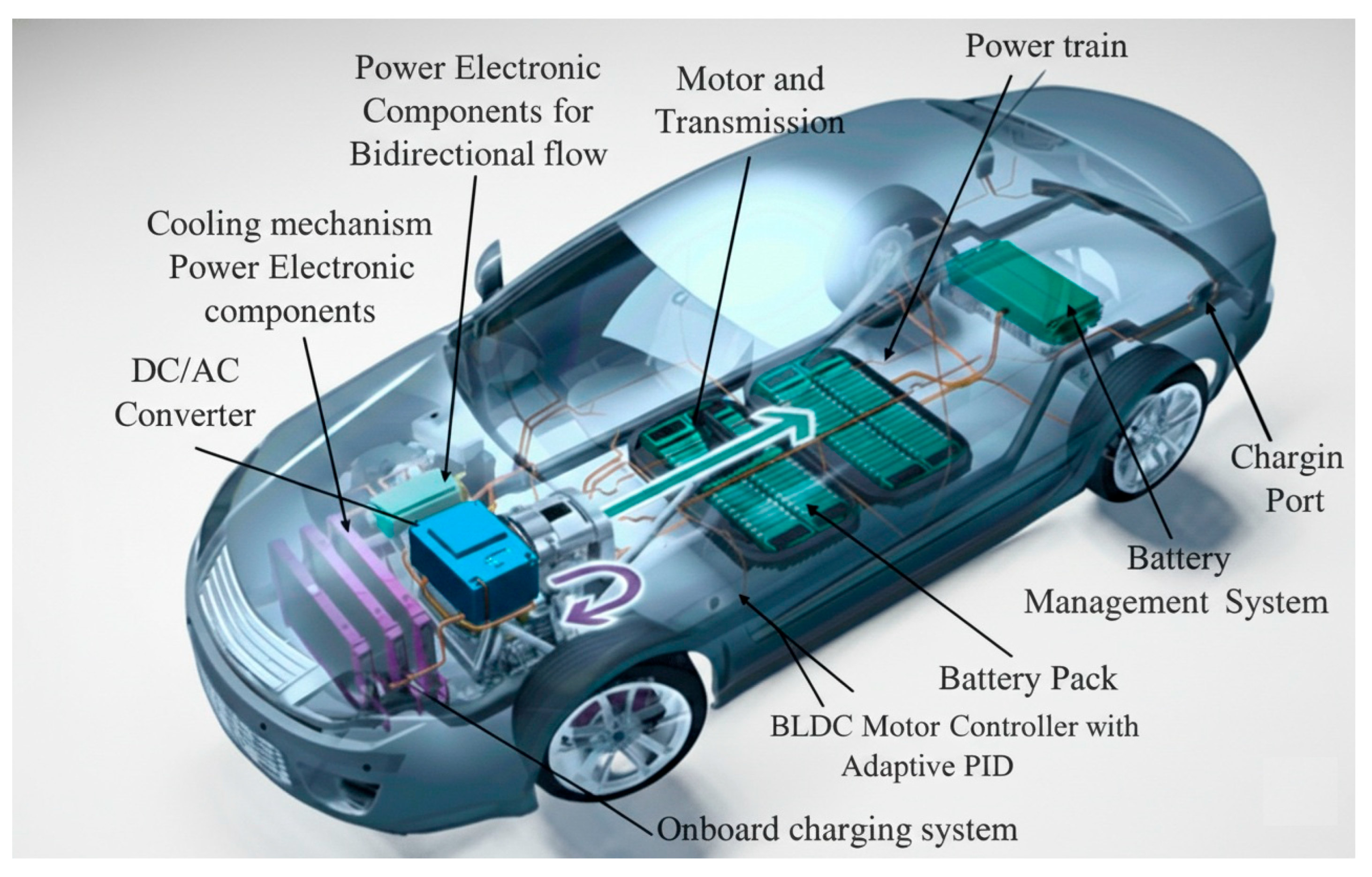
Figure 1.
Schematic architecture of an Electric Vehicle (EV) [1].
Figure 1.
Schematic architecture of an Electric Vehicle (EV) [1].
2. Materials and Methods
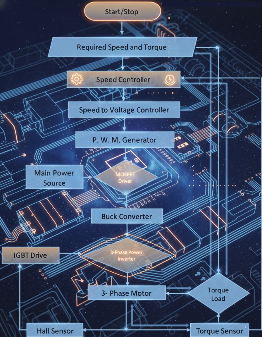
This study presents a specialized control architecture optimized for brushless DC (BLDC) motors within the electric vehicle powertrain. This research provides a rigorous mathematical derivation of the motor transfer function, followed by a modular MATLAB simulation of the control loop. As EV technology demands increasingly rugged and power-dense components, our research moves beyond standard control models to introduce a hybrid adaptive PID algorithm. This system integrates PID autotuning capabilities to maintain peak efficiency across variable load conditions, which is a critical factor for extending EV battery range. By synthesizing adaptive control with robust motor modeling, this research provides a scalable solution for the intelligent automation required in modern green energy transportation systems. Figure 2 shows the Step-by-Step Logic of the Proposed Controller.
This research establishes a high-fidelity simulation environment designed to validate a novel adaptive PID controller for Brushless DC motor applications. The platform serves as a digital twin for the physical BLDC motor system, allowing for the precise observation of control dynamics under variable operational loads. The simulation architecture is comprised of a 48V DC voltage source feeding a buck converter and a three phase power inverter which are modulated by MOSFET and IGBT drivers to ensure efficient power delivery. The control loop integrates voltage and current sensors with a specialized sensor block to feed real time data into the adaptive PID controller. This configuration enables the system to process input RPM and torque demands through a parameter conversion block, ultimately outputting performance metrics via integrated displays while maintaining system safety through a dedicated earthing protocol.
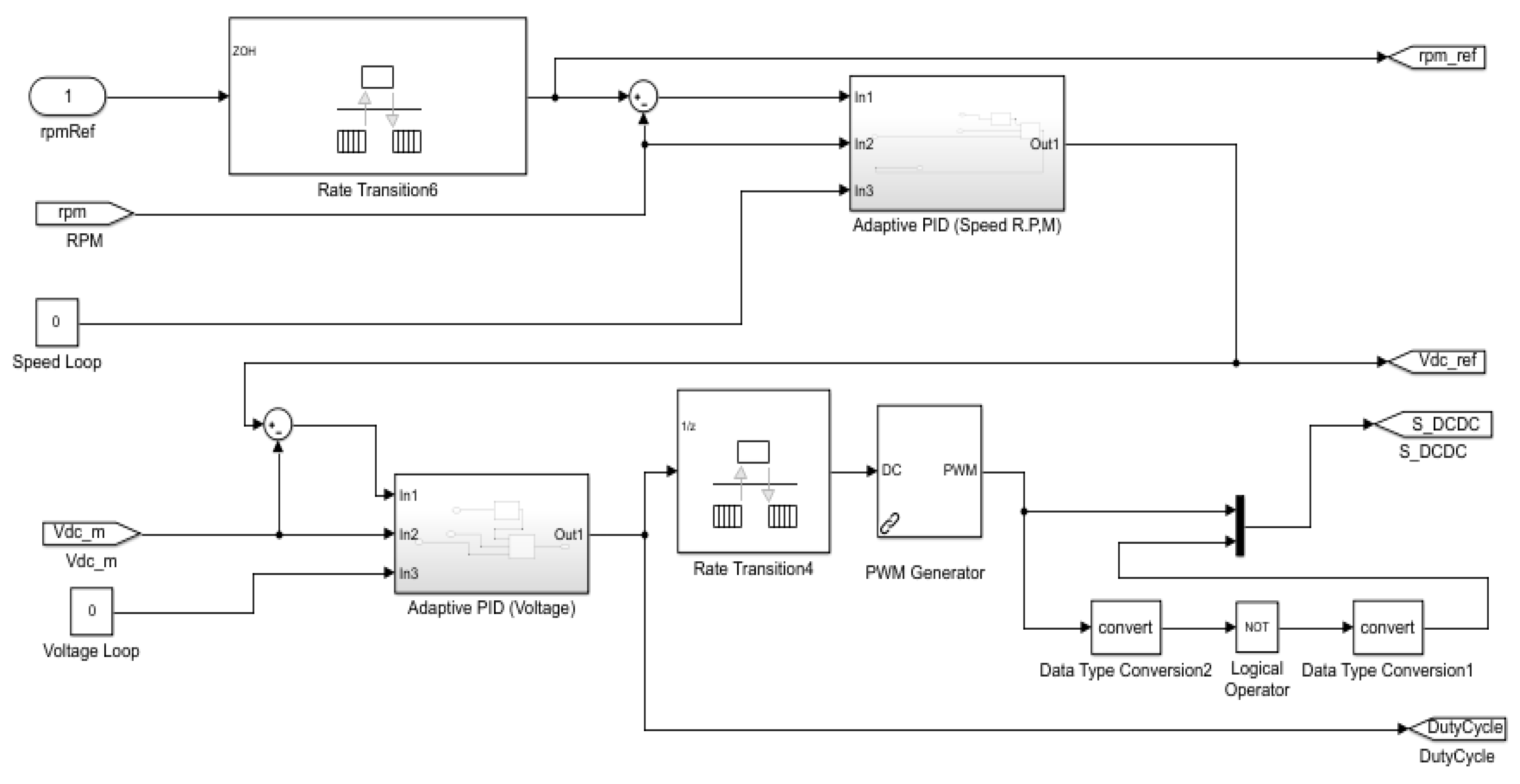
This design reflects a balanced relationship between speed and power, ensuring the motor operates with the wisdom and resilience needed for heavy-duty work. The controller acts as a dual-minded guide, with one unit watching over the RPM and the other guarding the voltage. Both units use our combined adaptive PID approach to ensure the transition from speed request to physical motion is smooth and efficient. By transforming the speed request into a voltage signal and then carefully shaping it through the PWM generator, we treat the energy with respect, using only what is necessary by breaking the signal into discrete, manageable parts. This approach is deeply beneficial for the heavy-duty motors used in community service vehicles, where preventing a magnetic stall is more important than simple speed. By closely monitoring the position of the magnetic poles, our controller ensures the motor remains strong and steady under heavy loads, proving its reliability for the demanding tasks of our people. Figure 4, the system employs a nested control strategy where the RPM command is initially processed as a voltage reference.
Figure 3.
Dynamic Simulation Framework for the Controller.
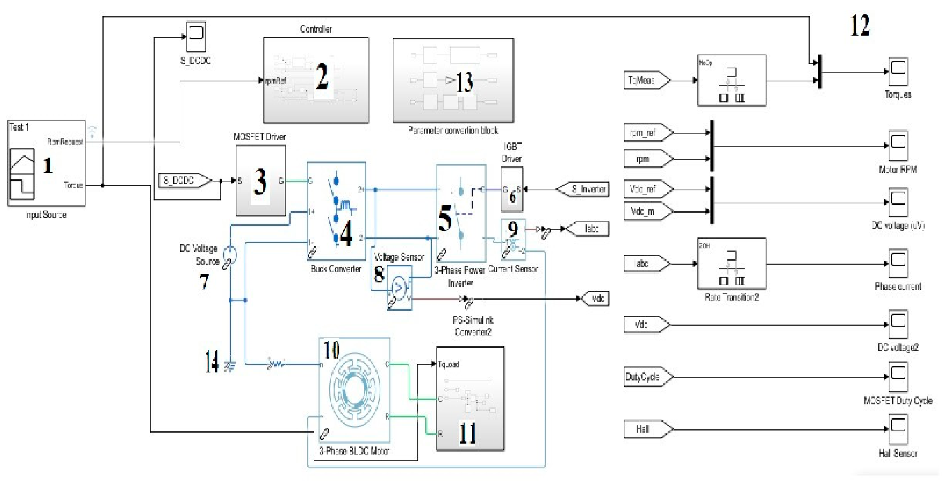
Figure 4.
Internal block diagrams of the controller block.
3. Results and Discussion
To evaluate the proposed adaptive PID controller against the derived motor equations, we established a rigorous testing platform designed to benchmark performance against existing control models. This section quantifies system response under variable speed, torque, and voltage conditions while providing empirical data on Hall sensor accuracy and MOSFET duty cycle efficiency. For a benchmark speed of 1000 RPM at Nm-1 torque and 48V source voltage, the simulation results in Figure 5 and Table 1 demonstrate high transient stability. Under a 10 Nm-1 load, the controller exhibited a negligible increase in rise time. The maximum overshoot was recorded at 1004.52 RPM (0.452%) under no-load conditions and 1002.97 RPM (0.397%) under load, highlighting the rapid response capability of the adaptive logic. Although the torque feedback loop introduced minor oscillations resulting in a maximum undershoot of 990.37 RPM (0.963%), these variations remain within acceptable tolerances for heavy-duty EV applications. While high-precision micro-systems might require an additional filter to smooth these oscillations, this design prioritizes raw frequency response and detectability to ensure robust operation under heavy-duty loads.
For 1200 RPM response test under a consistent 10 Nm-1 load and 48V source voltage. The adaptive PID controller successfully regulated the output at this elevated speed, though a marginal increase in rise time was observed in both load and no-load conditions. This slight delay is attributed to the increased inertia and voltage requirements associated with higher RPM setpoints. While benchmark controllers from existing literature often exhibit significant overshoot at these speeds, the proposed design maintained exceptional stability with an overshoot of only 0.49% under no-load conditions and 0.499% under load. Figure 6 illustrates the transient response at 1200 RPM while Table 1 provides the precise numerical data. These results confirm that while the percentage of overshoot increases slightly as the RPM requirements rise, the system remains well within the safety margins required for high-performance electric drivetrains.
We conducted a 1500 RPM speed test to determine the peak efficiency range of the proposed adaptive PID controller while maintaining all other system parameters. As the RPM setpoint increased, we observed a proportional extension in the settling time which remains consistent with the established operational capacity of the control logic. While the system demonstrated a robust ability to track the reference signal at this elevated speed, there was a measurable increase in both overshoot and undershoot during transient phases. Figure 7 provides a detailed visual analysis of these dynamics where the first highlighted block identifies the exact moment the controller output reaches the target reference and the second block captures the system response upon the application of torque. The numerical data compiled in Table 1 confirms that while the controller maintains high performance, the increased kinetic energy at 1500 RPM necessitates a more aggressive correction from the adaptive units to maintain equilibrium. To establish the operational boundary of the proposed system, we conducted a high velocity test at 1800 RPM under a 10 Nm-1 load and 48V source voltage. While the adaptive PID controller maintains stability under no load conditions, the application of torque at the 0.5 second mark reveals a significant performance threshold. As illustrated in Figure 8, the system experiences a substantial speed drop to 1576 RPM which represents a 12.444% deviation from the setpoint. This transient undershoot suggests that at high velocities the controller prioritizes torque production at the expense of rotational speed. The magnified response in the simulation displays a triangular waveform which indicates a limitation in the controller strength when managing high frequency demands. These empirical measurements provided in the accompanying Table 1 confirm that while the design is highly effective for low to mid range speeds, further optimization of the adaptive logic is required to mitigate torque induced speed losses in high speed heavy duty applications.
To assess the robustness of the adaptive PID architecture, we conducted a variable load test at a constant 1000 RPM with a 48V source. As shown in Figure 9, the controller demonstrated versatile performance across a multi-torque spectrum. Detailed inset windows provide a magnified view of the transient response as torque loads were incrementally applied. Data from Figure 10 indicates that while the peak RPM marginally shifted from 1005 RPM to 999.3 RPM as load increased, the system maintained high operational integrity. Interestingly, the lowest RPM values showed non-linear behavior, improving as torque approached the 10 Nm-1 design target before diverging under heavier loads. This trend suggests the adaptive logic is specifically optimized for the 10 Nm-1 benchmark.
Furthermore, as torque increased, we observed a reduction in overshoot percentage alongside a corresponding increase in undershoot. However, the Root Mean Square (RMS) values remained remarkably consistent, validating that the proposed controller delivers superior stability and energy efficiency across the targeted performance envelope.
The final stage of validation involves assessing the controller resilience against source voltage fluctuations which is a critical factor in EV battery management systems. To maintain the integrity of the power electronics, we observed the industry standard tolerance of 5% to 10% variation as defined by established literature. Operating a 48V system within a range of 43.22V to 52.8V is essential because rapid voltage flickers can increase thermal load on the motor primary resistance. This thermal buildup often degrades speed estimation accuracy and threatens the stability of the MOSFET drivers. Figure 11 displays the comparative results for 36V, 48V, and 60V configurations where the proposed adaptive PID controller maintained a tight tracking of the reference speed with minimal overshoot or undershoot even under varying loads. When benchmarked against traditional PID and Flower Pollination Algorithm (FPA) controllers, the proposed design consistently outperformed both in every metric. Specifically, the adaptive PID maintained overshoot below 1% at high speeds and exhibited significantly lower torque ripple than the FPA and PID models. These results confirm that the proposed adaptive logic provides superior adaptability and harmonic stability under the dynamic electrical conditions typical of an EV environment.
4. Conclusions
This research successfully engineers a hybrid adaptive PID control architecture by integrating classical PID and PID-autotuning methodologies into a singular cohesive platform. By utilizing Hall sensor feedback to manage speed control within complex operational environments, the system achieves precise output tracking without the need for an explicitly defined mathematical feedback loop. This dual-layer control strategy offers a cost-effective alternative to expensive high-power instrumentation while maintaining stability under unstable torque and voltage conditions. The architecture synthesizes the frequency-response estimation of the autotuner with the rugged, high-speed response of the standard PID unit. These components function as mutual correction layers to minimize overshoot and eliminate disturbances. The simulation phase demonstrated that the speed-control unit takes instantaneous corrective action while the voltage-control unit manages the PWM terminals. This signal flow is amplified through a sequence of MOSFET and IGBT drivers to bridge the gap between low-power logic and high-power motor terminals. Benchmark results in MATLAB Simulink confirm that the proposed controller maintains an overshoot threshold of less than 1% and consistently yields lower torque ripple than existing PID and FPA models.
References
- Biswas, P.; Rashid, A.; Habib, A. A.; Mahmud, M.; Motakabber, S. M. A.; Hossain, S.; Lei, T. M. Vehicle to Grid: Technology, Charging Station, Power Transmission, Communication Standards, Techno-Economic Analysis, Challenges, and Recommendations. World Electric Vehicle Journal 2025, 16(3), 142. [Google Scholar] [CrossRef]
- Mahmud, M.; Motakabber, S. M. A.; Alam, A. Z.; Nordin, A. N. Control BLDC motor speed using PID controller. International Journal of Advanced Computer Science and Applications 2020, 11(3), 477–481. [Google Scholar] [CrossRef]
- Mahmud, M.; Motakabber, S. M. A.; Alam, A. Z.; Nordin, A. N. Utilizing of flower pollination algorithm for brushless DC motor speed controller. In 2020 Emerging Technology in Computing, Communication and Electronics (ETCCE); IEEE: Dhaka, Bangladesh, 2020; pp. 1–5. [Google Scholar]
- Kuantama, E.; Vesselenyi, T.; Dzitac, S.; Tarca, R. PID and Fuzzy-PID control model for quadcopter attitude with disturbance parameter. Int. J. Comput. Commun. Control 2017, 12, 519–532. [Google Scholar] [CrossRef]
- Potnuru, D.; Mary, K.A.; Babu, C.S. Experimental implementation of Flower Pollination Algorithm for speed controller of a BLDC motor. Ain Shams Eng. J. 2019, 10, 287–295. [Google Scholar] [CrossRef]
- Suganthi, S.; Karpagam, R. Dynamic performance improvement of PMSM drive using fuzzy-based adaptive control strategy for EV applications. J. Power Electron. 2023, 23, 510–521. [Google Scholar] [CrossRef]
- Pradana, A.B.; Haque, M.M.; Krismanto, A.U.; Setiadi, H.; Nadarajah, M. Robust PID control of EV aggregator for C-FCAS using sequential multi-objective optimization. IEEE Access 2024, 12, 12602–12617. [Google Scholar] [CrossRef]
- Davoudkhani, I.F.; Zare, P.; Abdelaziz, A.Y.; Bajaj, M.; Tuka, M.B. Robust load-frequency control of islanded urban microgrid using 1PD-3DOF-PID controller including mobile EV energy storage. Sci. Rep. 2024, 14, 13962. [Google Scholar] [CrossRef] [PubMed]
- Shenbagalakshmi, R.; Mittal, S.K.; Subramaniyan, J.; Vengatesan, V.; Manikandan, D.; Ramaswamy, K. Adaptive speed control of BLDC motors for enhanced electric vehicle performance using fuzzy logic. Sci. Rep. 2025, 15, 12579. [Google Scholar] [CrossRef] [PubMed]
- Saiteja, P.; Ashok, B.; Upadhyay, D. Evaluation of electric vehicle performance characteristics for adaptive supervisory Self-Learning-Based SR motor energy management controller under Real-Time driving conditions. Vehicles 2024, 6, 509–538. [Google Scholar] [CrossRef]
- Chu, L.; Li, H.; Xu, Y.; Zhao, D.; Sun, C. Research on longitudinal control algorithm of adaptive cruise control system for pure electric vehicles. World Electric Vehicle Journal 2023, 14, 32. [Google Scholar] [CrossRef]
Figure 2.
Step-by-Step Logic of the Proposed Controller.
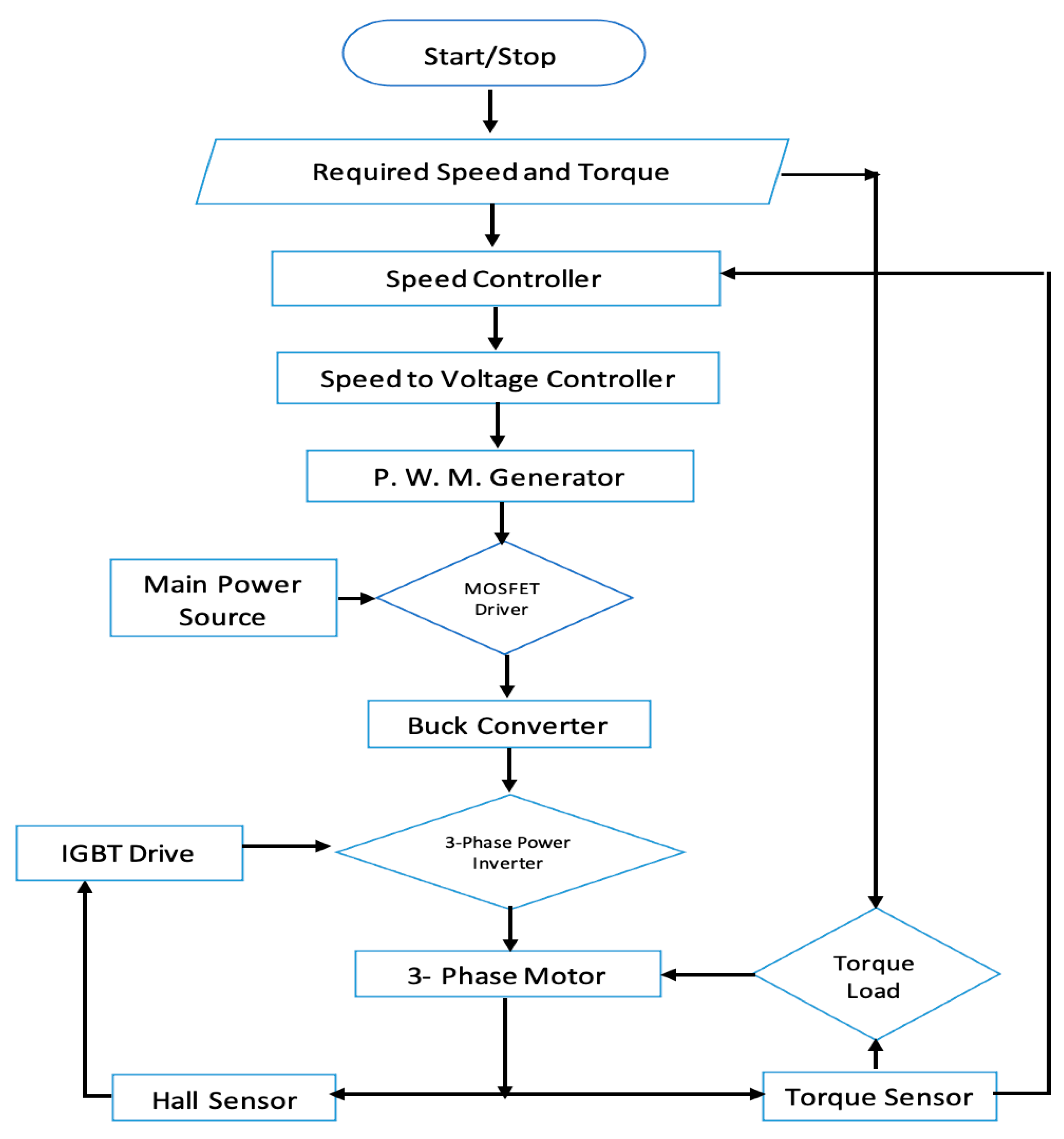
Figure 5.
RPM-1000 with preselected torque -10Nm-1 and source voltage 48V.
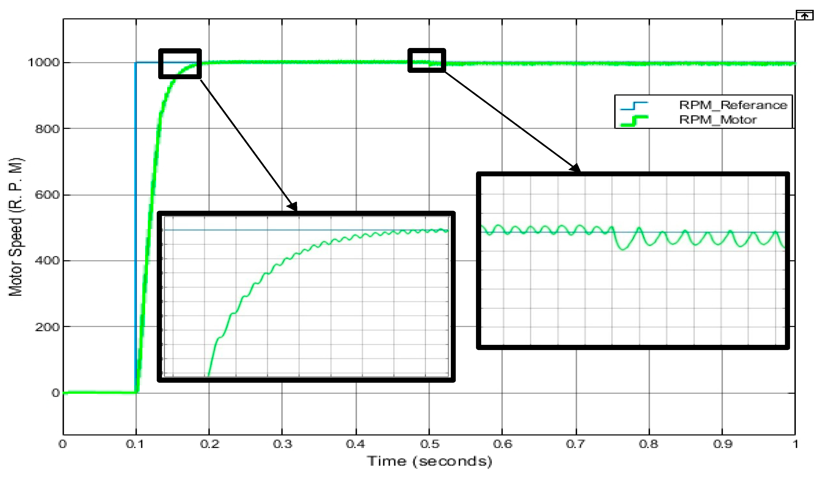
Figure 6.
RPM-1200 with preselected torque -10Nm-1 and source voltage 48V.
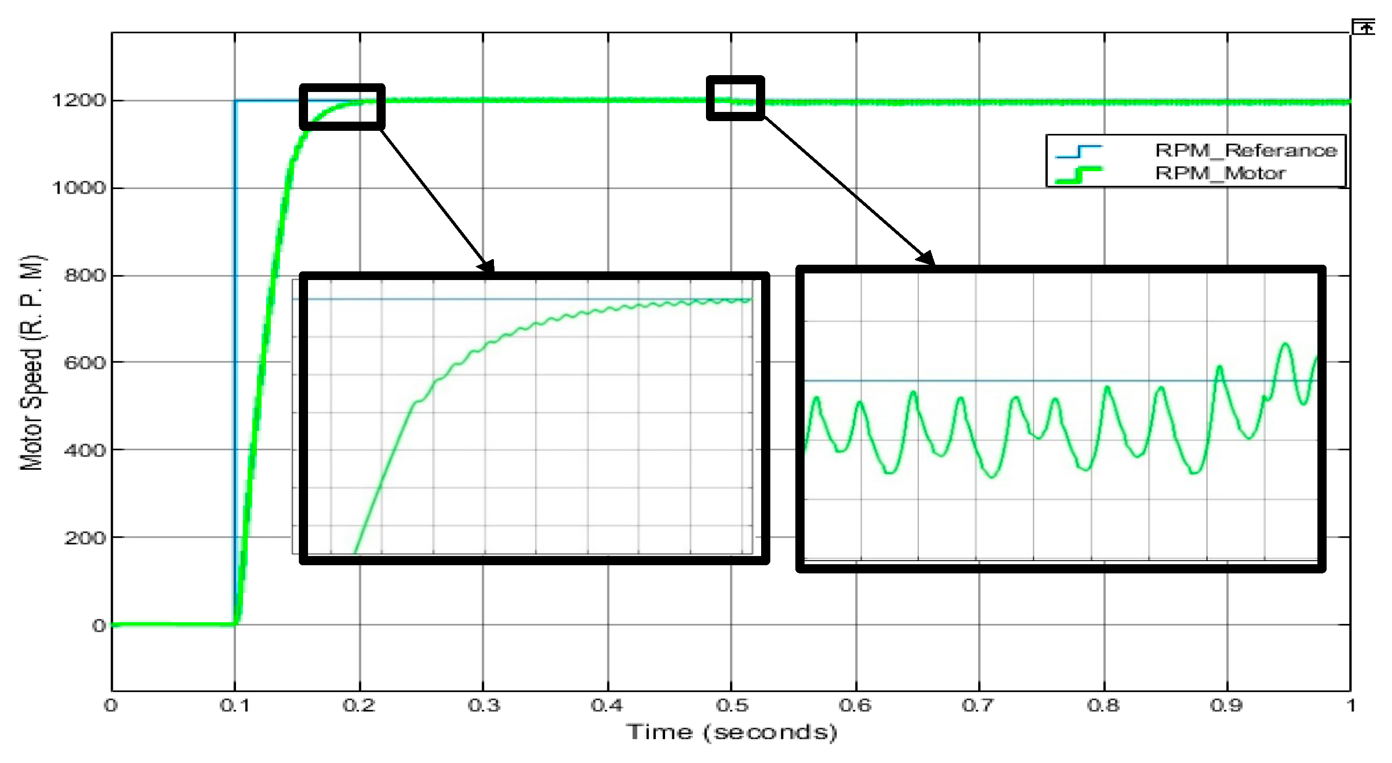
Figure 7.
RPM-1500 with preselected torque -10Nm-1 and source voltage 48V.
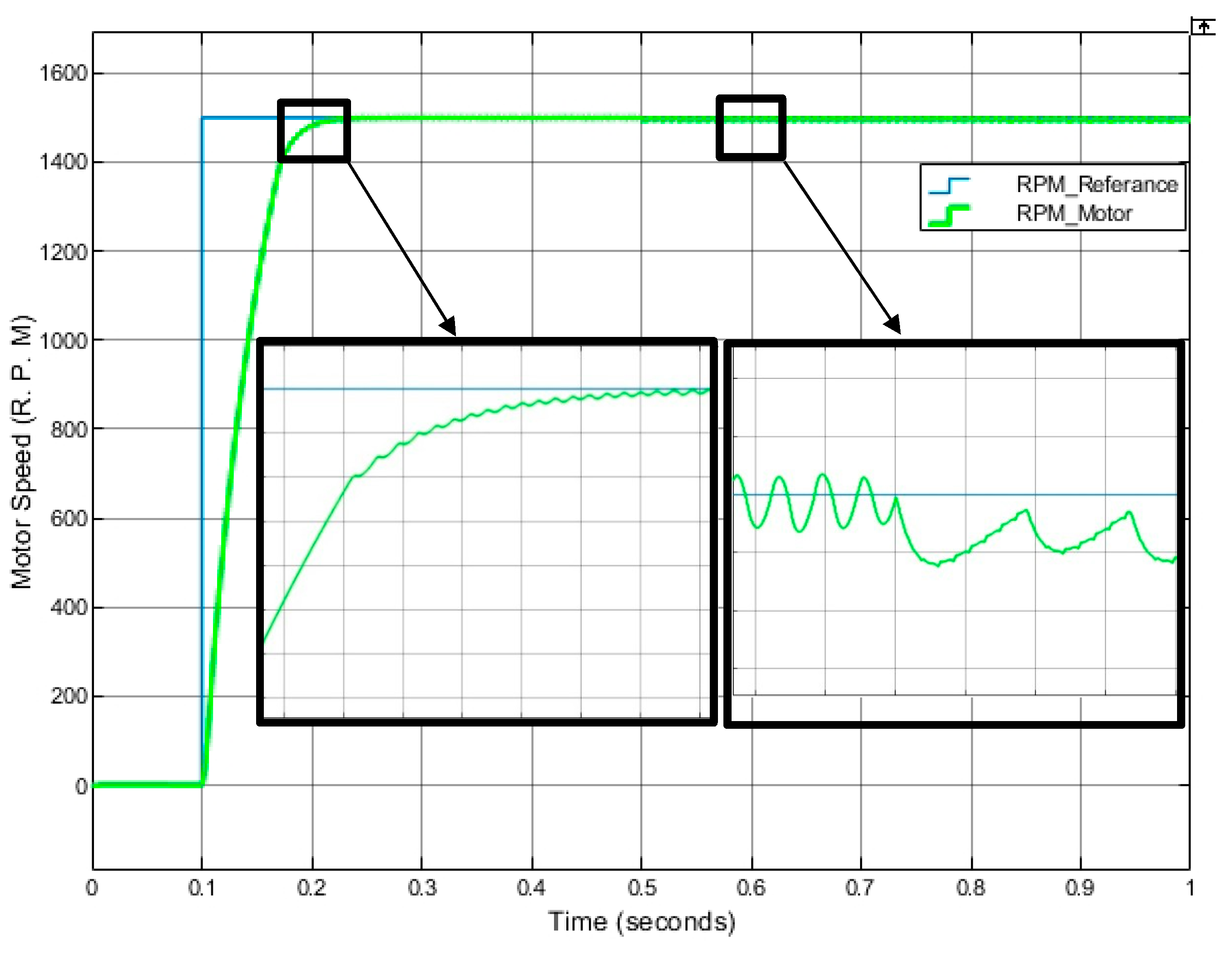
Figure 8.
RPM-1800 with preselected torque -10Nm-1 and source voltage 48V.
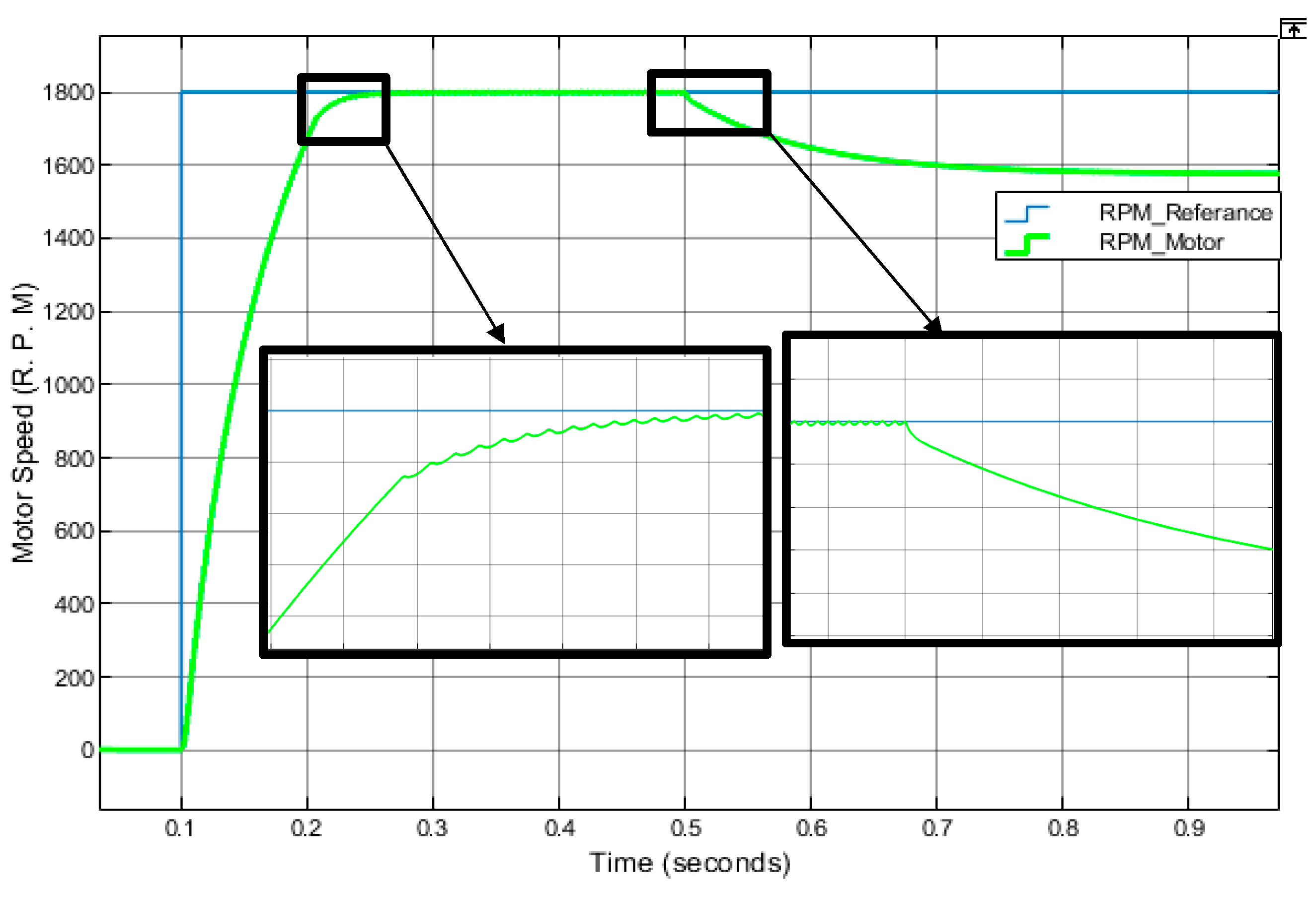
Figure 9.
Controller performance in a single simulation for variable torque.
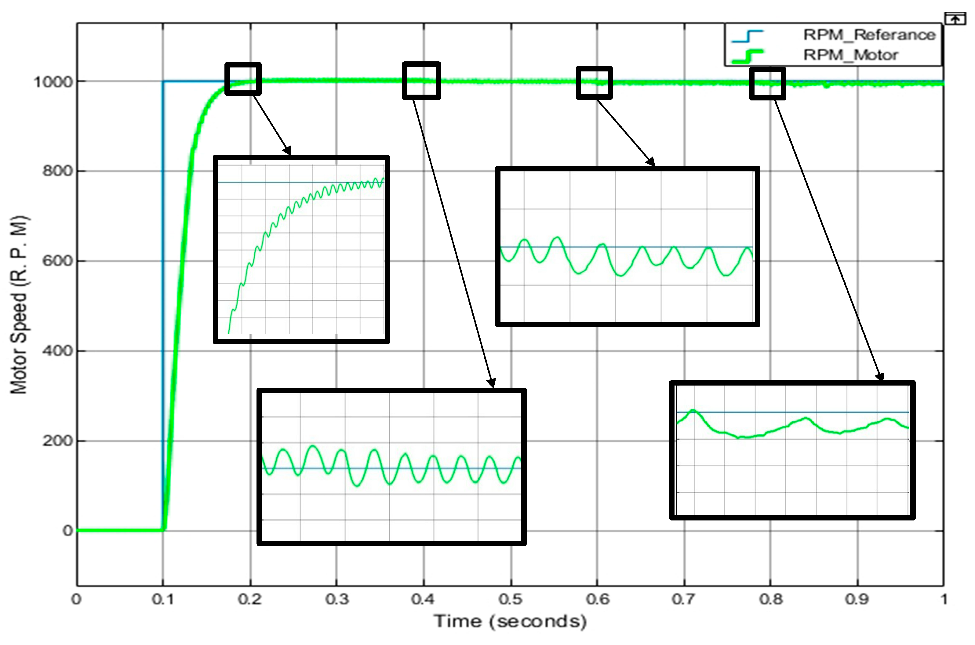
Figure 10.
Torque performance in brief.
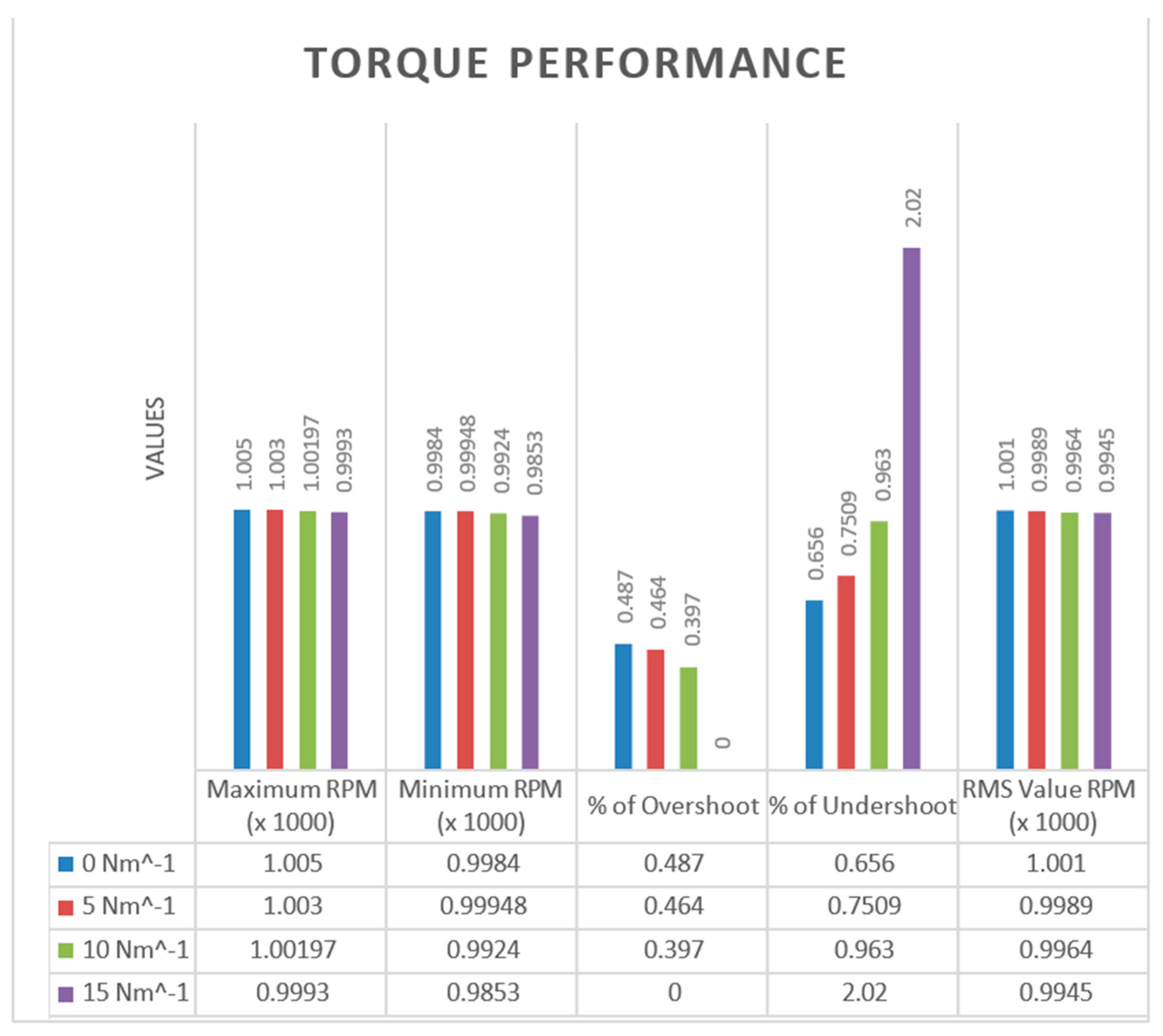
Figure 11.
Controllers’ output with variable voltage, while speed 1000 RPM and torque 10 Nm⁻¹.
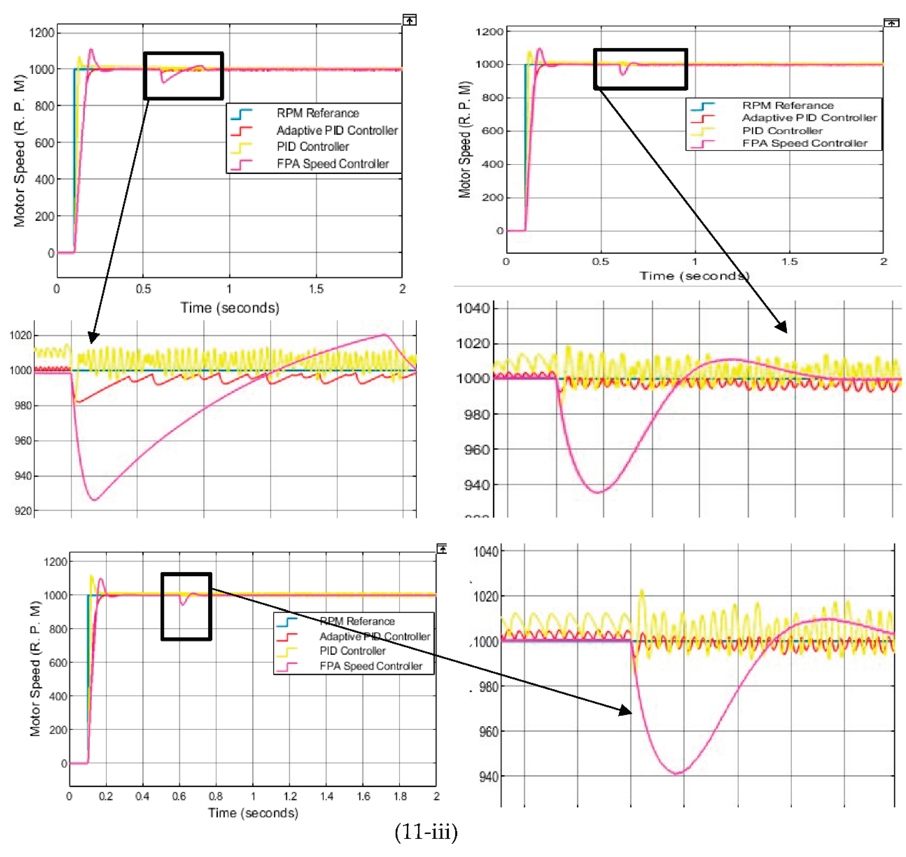

Table 1.
Simulated measurements for 1000RPM, 1200 RPM, 1500 RPM and 1800RPM.
| Measurements | Time for 1000 RPM | Time for 1200 RPM | Time for 1500 RPM | Time for 1800 RPM |
| Rising time (No load/ with load) | 0.03638s / 0.05154s | 0.04343s / 0.0739s | 0.06006s / 0.13549s | 0.08526s / 0.13549s |
| Max / Min high | 1004.52 RPM / 998.939 RPM | 1203 RPM / 1196.388 RPM | 1502 RPM / 1488.287 | 1801 RPM / 1550.388 RPM |
| With Load maximum high | 1002.97 RPM | 1204 RPM | 1497 RPM | 1576 RPM |
| Overshoot | 0.452% | 0.490% | 0.502% | 0.505% |
| With load overshoot | 0.397% | 0.499% | 0.305% | 0% |
| With load undershoot | 0.963% | 1.993% | 1.998% | 12.444% |
Disclaimer/Publisher’s Note: The statements, opinions and data contained in all publications are solely those of the individual author(s) and contributor(s) and not of MDPI and/or the editor(s). MDPI and/or the editor(s) disclaim responsibility for any injury to people or property resulting from any ideas, methods, instructions or products referred to in the content. |
© 2026 by the authors. Licensee MDPI, Basel, Switzerland. This article is an open access article distributed under the terms and conditions of the Creative Commons Attribution (CC BY) license (http://creativecommons.org/licenses/by/4.0/).
Copyright: This open access article is published under a Creative Commons CC BY 4.0 license, which permit the free download, distribution, and reuse, provided that the author and preprint are cited in any reuse.


