Submitted:
06 February 2026
Posted:
09 February 2026
You are already at the latest version
Abstract
The complexity of an extrusion die profile is determined by its geometry. Various metrics such as the complexity index, shape factor, and form factor are used to quantify how geometric intricacy affects production cost, die life, energy consumption, product quality, and overall manufacturability. Bearing geometry plays a critical role at controlling metal flow and tool life in aluminum extrusion. In this study a simulation based investigation is performed to investigate the influence of bearing geometry on extrusion behavior using the finite element method. Two extrusion dies are examined. A single cavity die with uniform bearing geometry and a dual cavity die with controlled bearing geometry modification in one cavity. The results show that the bearing modification in the dual-cavity die causes severe flow imbalance, with exit velocity deviations. This imbalance leads to localized pressure amplification, increased thermal gradients, and stress concentration in critical die regions. In contrast, the single-cavity die because of the simple geometry, exhibits uniform flow, stable pressure evolution, and low tool stress. These findings demonstrate the high sensitivity of multi-cavity extrusion dies to bearing geometry and highlight the importance of simulation-driven die design for achieving balanced flow and improved tool performance.
Keywords:
metal forming
; aluminium extruction
; extraction die
; elastoplastic finite element modeling
1. Introduction
Aluminum extrusion is one the most widely used metal forming processes. Due to its favorable strength to weight ratio and corrosion resistance aluminum is extensively employed in automotive, construction and energy systems. In extrusion processes the final product quality, production efficiency and tool life are strongly influenced by the design of the extrusion die.
Among the various die design parameters, bearing geometry plays a dominant role in controlling metal flow, extrusion pressure, temperature and stress development within the tool. Variations in bearing length or angle lead to different material velocity at the die exit and uneven surface quality witch significant changes the extruded profile.
Using thermo-mechanical finite element simulations, the present study evaluates the effects of bearing geometry on metal flow velocity, extrusion pressure, temperature evolution, and tool stress. In particular, the relationship between die geometry, extrusion process parameters, and the resulting aluminum profile characteristics are investigated through a combination of theoretical review, geometric classification, and CAD-CAE-based simulation.
2. State of the Art
Extrusion is a fundamental metal-forming technique that transforms cast ingots into products with useful cross-sections and mechanical properties. The process relies on plastic deformation. Extrusion methods are generally classified as direct or indirect. In direct extrusion, the ram moves in the same direction as the material flow, while in indirect extrusion, the die moves toward a stationary billet, reducing friction between the billet and the container. Indirect extrusion typically produces superior dimensional accuracy and surface finish but at lower production rates. Direct extrusion, on the other hand, offers higher throughput but requires careful control of process parameters to maintain quality.
Aluminum, the third most abundant element in the Earth’s crust, is ideally suited to extrusion due to its excellent malleability, corrosion resistance, and strength-to-weight ratio. Hot extrusion, carried out at elevated temperatures, reduces flow stress, shortens processing time, and enables larger reductions in cross-sectional area. During direct extrusion, a cylindrical aluminum billet is placed in the container and compressed by a hydraulic ram through a die opening that defines the cross-section of the final product. A dummy block is positioned between the ram and billet to prevent contamination and tool wear..
A schematic of the direct extrusion process is shown in Figure 1. Further technological details can be found in monographs [1,2,3,4,5,6].
During hot extrusion, temperature variations between the billet and the tooling can cause inconsistent flow and mechanical properties. To mitigate these effects, process parameters such as billet temperature, ram speed, lubrication, and die design must be carefully optimized.
2.1. Metal Extrusion
Metal extrusion is a fundamental manufacturing process in which a billet is forced through a die to produce long components with a constant cross-section. The method combines principles of plastic deformation and material flow under high compressive stress.
Extrusion can be performed hot or cold, depending on whether the billet is heated above its recrystallization temperature. Hot extrusion minimizes flow stress and improves formability, making it the preferred approach for aluminum and its alloys. Cold extrusion, although requiring higher pressures, provides superior dimensional accuracy and surface finish.
The basic equipment for an extrusion line includes:
- A hydraulic press, responsible for applying pressure on the billet.
- A container, which holds the billet during compression.
- A die, defining the final shape.
- Auxiliary components, such as dummy block, stem, and shears.
The direct extrusion process—widely used in the aluminum industry—forces the billet and ram to move in the same direction. Indirect extrusion, by contrast, moves the die toward a stationary billet, reducing friction and improving surface quality.A successful extrusion operation depends on careful control of temperature, ram speed, lubrication, and die geometry. Variations in these parameters affect metal flow, internal stresses, and surface integrity. Figure 2 illustrates the basic components of a hot aluminum extrusion press.
2.2. Shape Complexity
The complexity of an extruded profile is primarily defined by its cross-sectional geometry. Complex shapes may contain thin walls, enclosed cavities, or intricate features, all of which influence material flow and die wear.
Quantifying this complexity is essential for predicting manufacturing cost, required extrusion pressure, die life, and production feasibility. Several researchers have proposed methods to express profile complexity mathematically. For instance, one common measure is the Shape Complexity Factor (C₁), proposed by Lakshmanan:
where:
C1=P/A
P = perimeter of the cross-section (mm)
A = area of the cross-section (mm²)
Higher C₁ values correspond to thinner sections and more complex shapes.
Another useful indicator is the Form Factor (C₂), which accounts for shape slenderness and aspect ratio:
C2=P2/4πA
For a perfect circle, C₂ = 1, while higher values denote increasingly irregular or elongated shapes.
The Shape Ratio (C₃) relates the maximum and minimum dimensions of the cross-section:
C3=D_max/D_min
This ratio is often employed to assess extrusion die difficulty and predict flow imbalance across the section.
In practice, these factors are used together to classify profiles as simple, moderately complex, or highly complex.
2.3. Terminology and Classification
Extruded profiles are grouped into three main categories based on the presence and arrangement of cavities in their cross-sections:
- Solid Profiles – Shapes without any enclosed voids (e.g., bars, rods, angles).
- Semi-Hollow Profiles – Shapes with partially enclosed cavities or narrow gaps (e.g., channels, asymmetric T-sections).
- Hollow Profiles – Shapes with one or more completely enclosed voids (e.g., tubes, boxes).
Each class requires a specific die configuration:
- Solid dies for simple sections.
- Port-hole or bridge dies for hollow sections.
- Combination dies for semi-hollow geometries.
The choice of die type affects not only product geometry but also metal flow, extrusion load, and the likelihood of defects such as tearing or surface laps.
2.4. Pressure-based Definition of Complexity
While geometric indices describe profile shape, pressure-based complexity provides a more practical measure related to manufacturing effort. This approach correlates the required extrusion pressure with the reference pressure for a circular bar of equal cross-sectional area.
According to [6], the Relative Extrusion Pressure (Rₚ) is defined as:
R_p=P_shape/P_circle
where:
Pshape = measured pressure for the actual profile,
Pcircle = pressure for a circular reference section.
Higher Rₚ values indicate more complex shapes requiring greater forming energy.
This pressure-based method complements geometric complexity factors, allowing engineers to predict not only die difficulty but also energy consumption and press load capacity
2.5. Overview of Die Designs and Categories
In the extrusion process, the die is the most critical tool because it defines the shape, dimensional accuracy, and surface quality of the final product.
An extrusion die is a thick steel plate with one or more precisely machined openings that determine the cross-sectional geometry of the extrudate.
Dies operate under extreme conditions of temperature, pressure, and friction. Typical contact pressures may exceed 500 MPa, and die surface temperatures can reach 500 °C during hot extrusion. Therefore, dies are usually manufactured from hardened tool steels such as H13, and are often nitride to enhance wear resistance and thermal fatigue life.
A properly designed die ensures:
- Uniform metal flow across the cross-section
- Balanced pressure distribution
- Minimal defects such as tearing or flow lines
- Efficient material utilization and longer tool life
Depending on their design, dies may be categorized as:
- Solid-dies
- Semi-Hollow dies
- Hollow dies
- Special cases.
2.6. Die Design Considerations
Designing an efficient extrusion die requires balancing geometry, material flow, and mechanical integrity.
The following factors are crucial:
- Profile Geometry and Complexity – Determines die configuration, bearing length, and flow balancing features. Complex hollow shapes require multi-part dies with welding chambers.
- Material Flow Uniformity – Achieved by adjusting bearing lengths, entry angles, and flow channels to equalize velocity across the section.
- Bearing Length Optimization – Longer bearings increase resistance and slow flow; shorter bearings accelerate flow. Proper tuning prevents defects such as twist or dimensional distortion.
- Thermal Management – Uniform die temperature is essential to avoid uneven flow or premature die failure. Pre-heating and controlled cooling systems are commonly employed.
- Strength and Rigidity – The die must withstand extrusion pressures without distortion. Finite element analysis (FEA) is often used to predict stress distribution.
- Ease of Manufacture and Maintenance – Simpler dies reduce machining cost and downtime. Modular designs allow easier cleaning and component replacement.
A well-designed die not only produces accurate and defect-free profiles but also reduces energy consumption and extends tool life.
3. Numerical Methodology
The numerical analysis of the aluminum extrusion process was conducted using Altair inspire extrude metal. The software enables fully coupled thermomechanical simulations of hot extrusion processes, accounting for large plastic deformation, material behavior and contact interactions between the billet and the die assembly. The present investigation has been inspired by relevant references advocating computational mechanics’ tools [13,14].
Direct hot extrusion conditions were assumed for all cases. The billet and die assembly were initialized at uniform temperature of 450°C, while a constant ram speed of 5mm/s was applied. Ambient temperature was set to 25 °C. Apart from geometric differences between the examined dies, all process parameters were kept identical to isolate the influence of die and bearing geometry on extrusion behavior.
4. Case Studies Description
To investigate the influences of die geometry and bearing design on aluminum extrusion performance, two industrially representative extrusion dies with different levels of geometric complexity were selected as case studies. The dies were choses to enable a direct comparison between a simple-balanced extrusion and a more complex multicavity design in which localized geometric modification could be evaluated.
The selected dies represent two common scenarios encountered in industrial practice:
- A single cavity die designed for stable and uniform extrusion
- A dual cavity die intended to increase productivity but is more sensitive to flow imbalance.
Profile A – Single Cavity Extrusion die
This die incorporates a single bearing region with constant height and smooth curvature, designed to promote uniform metal flow. The CAD model is shown in Figure 3.
The simplicity of the profile allows the extrusion process to operate with minimal disturbance to material flow. No internal cavities or asymmetries are present. As result profile A serves as a refence configuration, representing a baseline case for stable extrusion behavior.
Profile B, Dual Cavity Extrusion Die
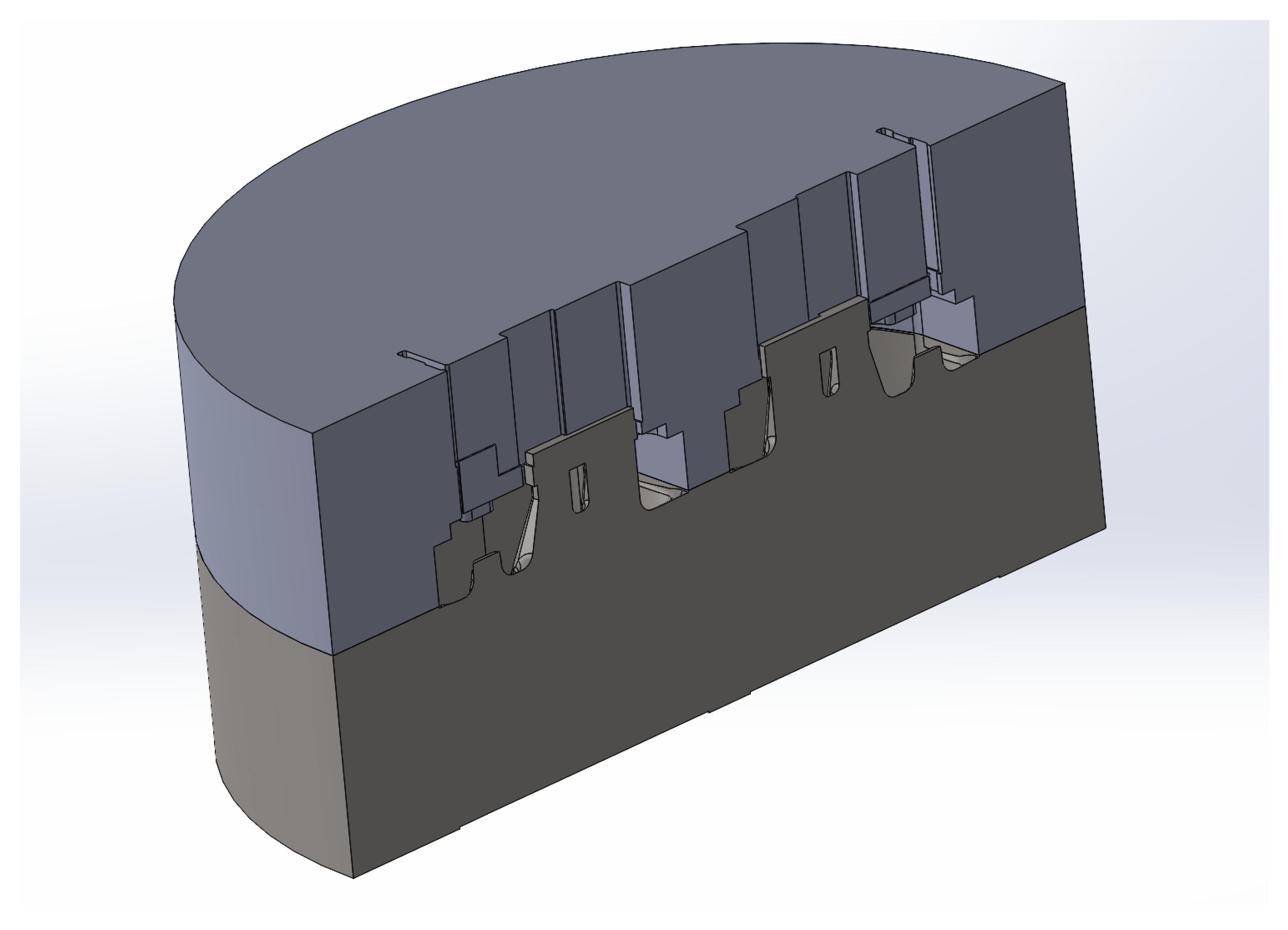
Profile B represents a more complex dual cavity extrusion die, designed to produce two aluminum profiles simultaneously within a single die block. In this configuration, both cavities share a common die body and welding chamber, while each cavity contains its own bearing region and flow channel.
To further study the effect of bearing geometry on extrusion, a controlled geometric modification was introduced in one cavity of profile B. The modification was intentionally limited to the bearing region, while all other aspects remained unchanged.
Specifically:
- Cavity 1 retains the original industrial bearing geometry, featuring variable bearing length and curvature optimized for balanced flow.
- Cavity 2 incorporates a simplified bearing design, in which the original geometry is replaced by flattened bearing surface of constant height.
The CAD model is shown in Figure 4.
5. Simulation Results
Thermo-mechanical finite element simulations were successfully completed for both extrusion dies under identical prices conditions. The results are presented in terms of velocity fields, pressure distributions, temperature contours and die stress (von misses) maps.
5.1. Profile A
The simulated extrusion process for profile A required a total ram force of 13.65MN, corresponding to a maximum extrusion pressure of about 535MPa. Pressure peaks were concentrated near the die entrance and bearing transition zone
The smooth pressure gradient and lack of localized pressure spikes suggest efficient load transfer and low flow resistance.
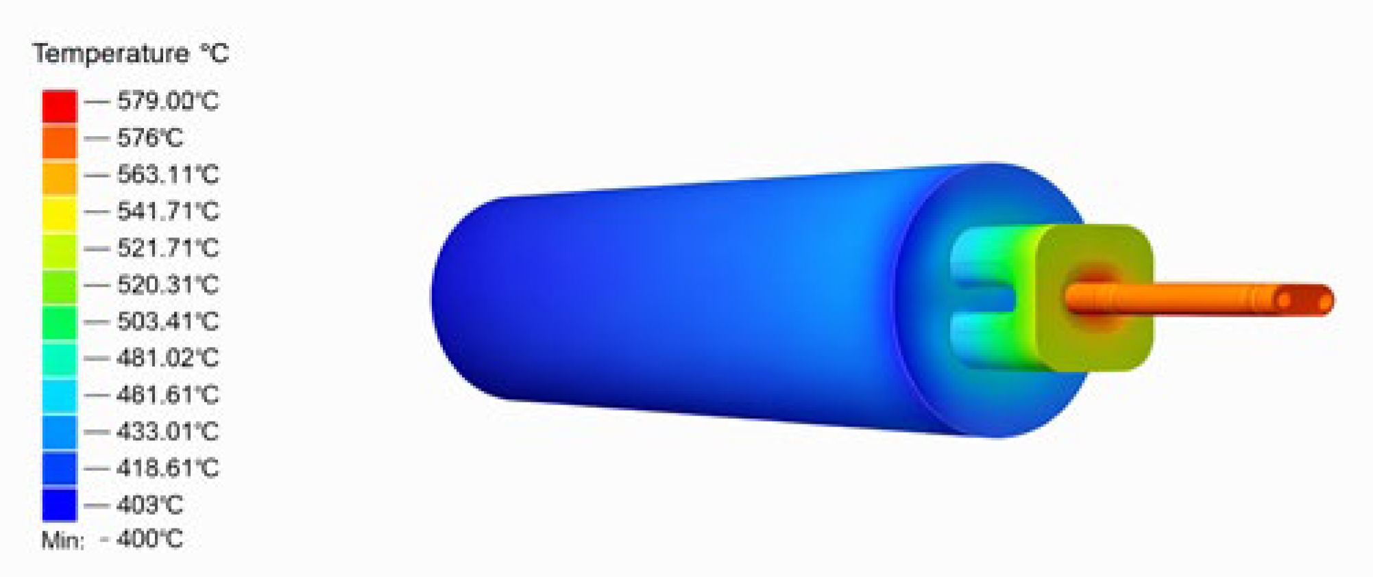
The overall temperature variation across the profile cross-section did not exceed 1.4%, indicating balanced heat generation due to plastic deformation and friction.
The von Mises stress distribution in the die body shows a maximum stress level of approximately 56.6MPa, located near the bearing choke region. These stress levels are far below the yield strength of the tool steel at operating temperature, indicating a substantial safety margin and minimal risk of plastic deformation.
Figure 5.
Velocity contours.
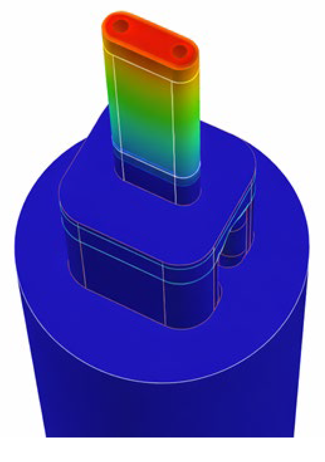
Figure 6.
Velocity contours.
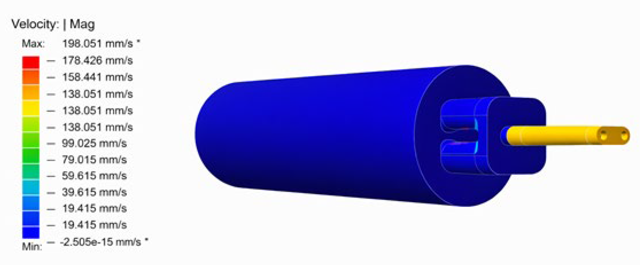
Figure 7.
Pressure contours.
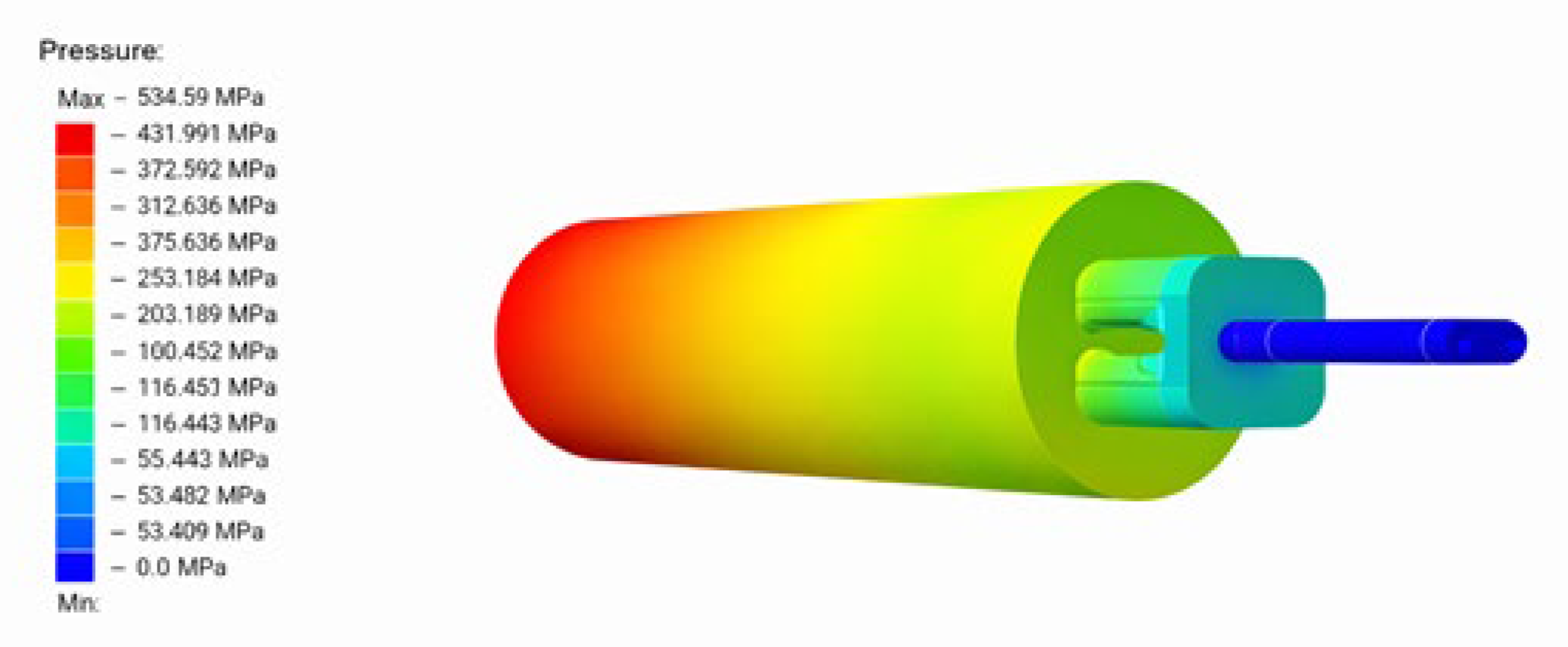
Figure 8.
Temperature contours
5.2. Profile B
The cavity incorporating the flattened bearing geometry exhibited significantly higher exit velocities, with a maximum value of 643mm/s, more than three times that observed in profile A.
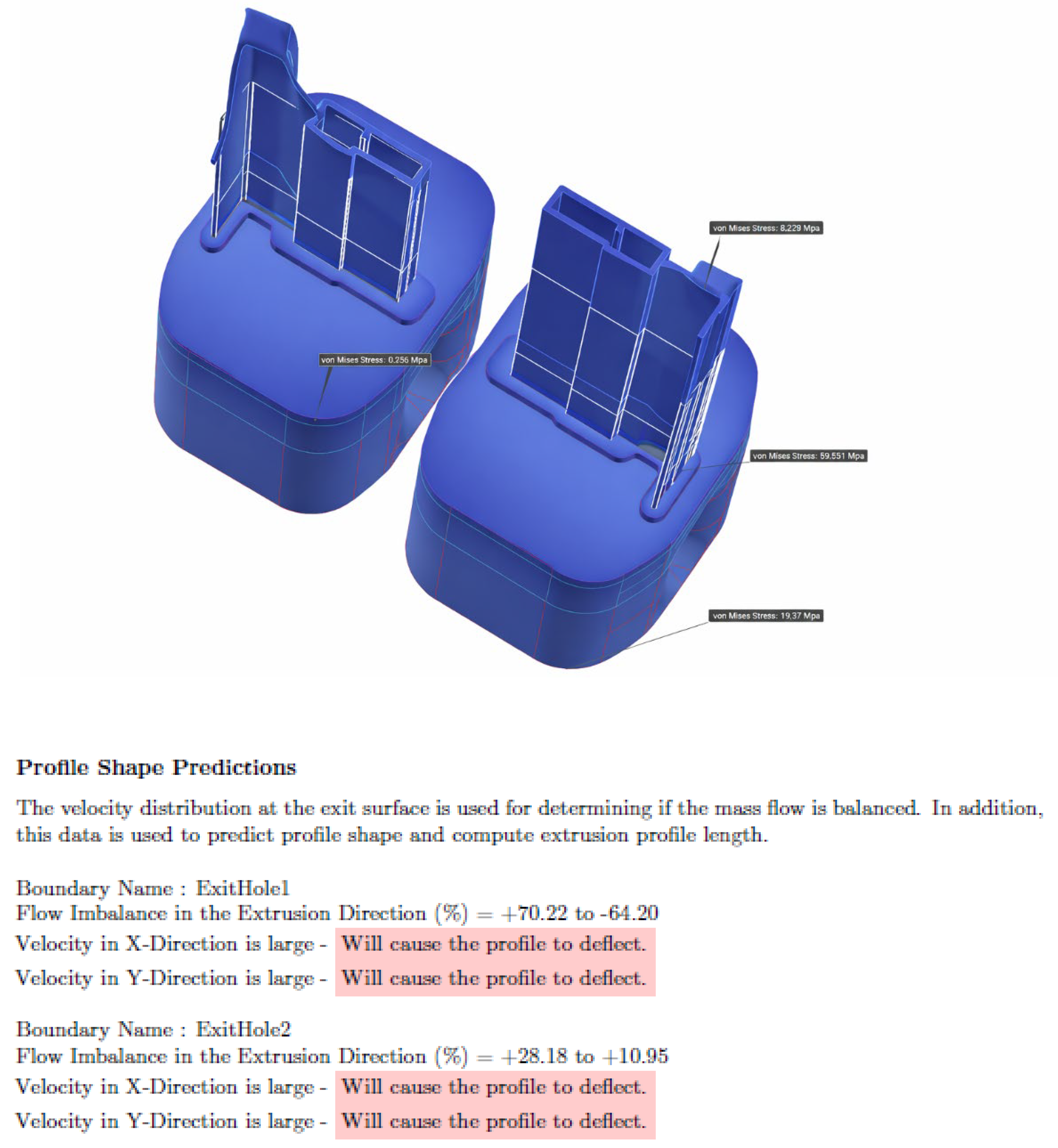
Velocity imbalance between the two exit holes was substantial, reaching deviations of up to +70% in the extrusion direction for one cavity, and +28% for the second. These deviations clearly demonstrate that the bearing geometry modification strongly affects flow resistance and material distribution within the die.
The maximum extrusion pressure for profile B reached 489.6MPa, with localized pressure peaks concentrated near the porthole entrance and the modified bearing region.
Maximum temperature reached approximately 551 °C
Surface temperature variation across the profile ranged from approximately 1.0% to 2.9%, reflecting the influence of uneven metal flow and differential deformation rates between the two cavities. Although these values remain within acceptable industrial limits, the increased thermal imbalance may affect weld quality and surface consistency in multi-cavity extrusion.
The Von Mises stress distribution for Profile B indicates a maximum stress level of approximately 62.6 MPa, located at the intersection between the bridge structure and the flattened bearing region.
Figure 9.
Details of the analysis.
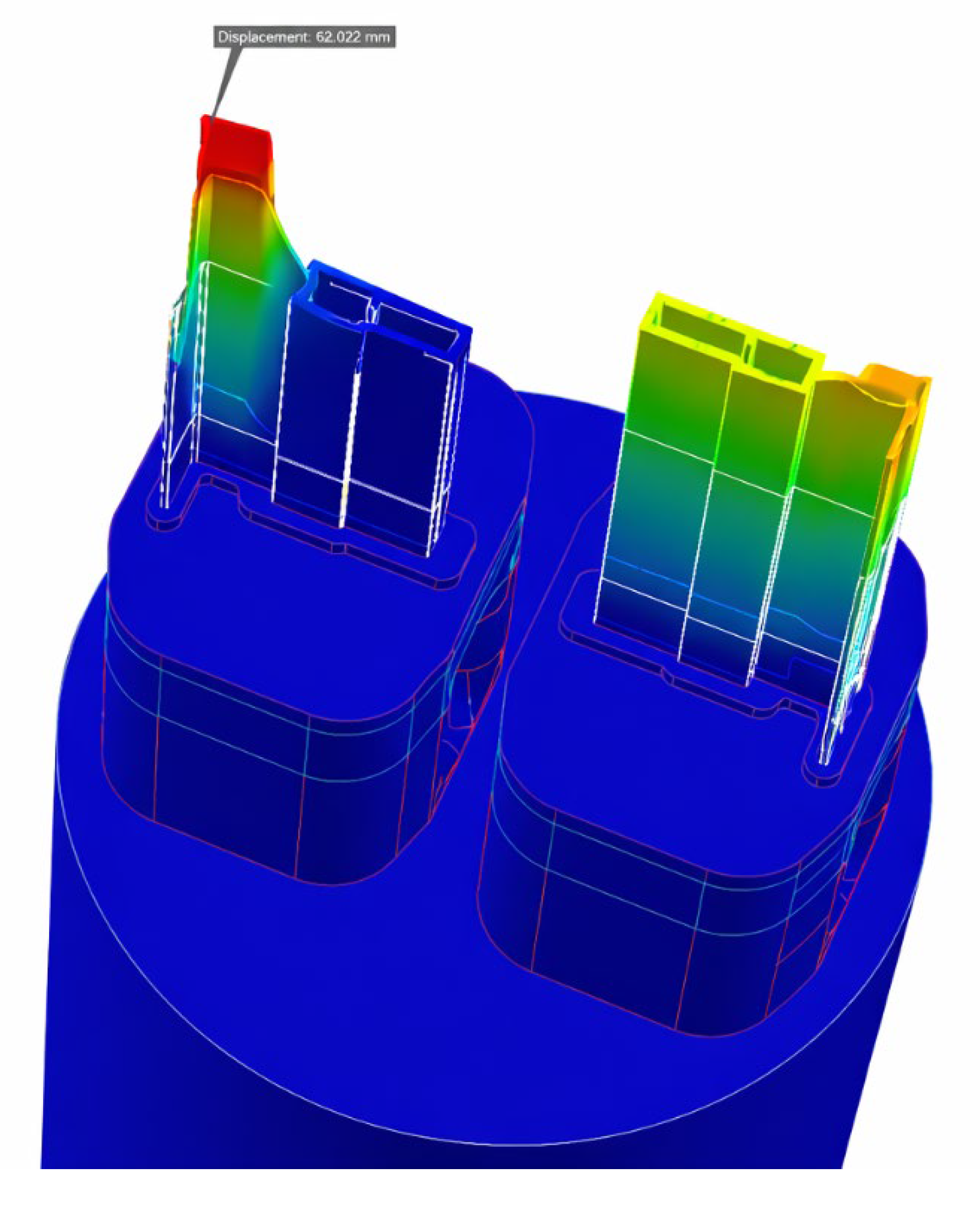
Figure 10.
Velocity contours.
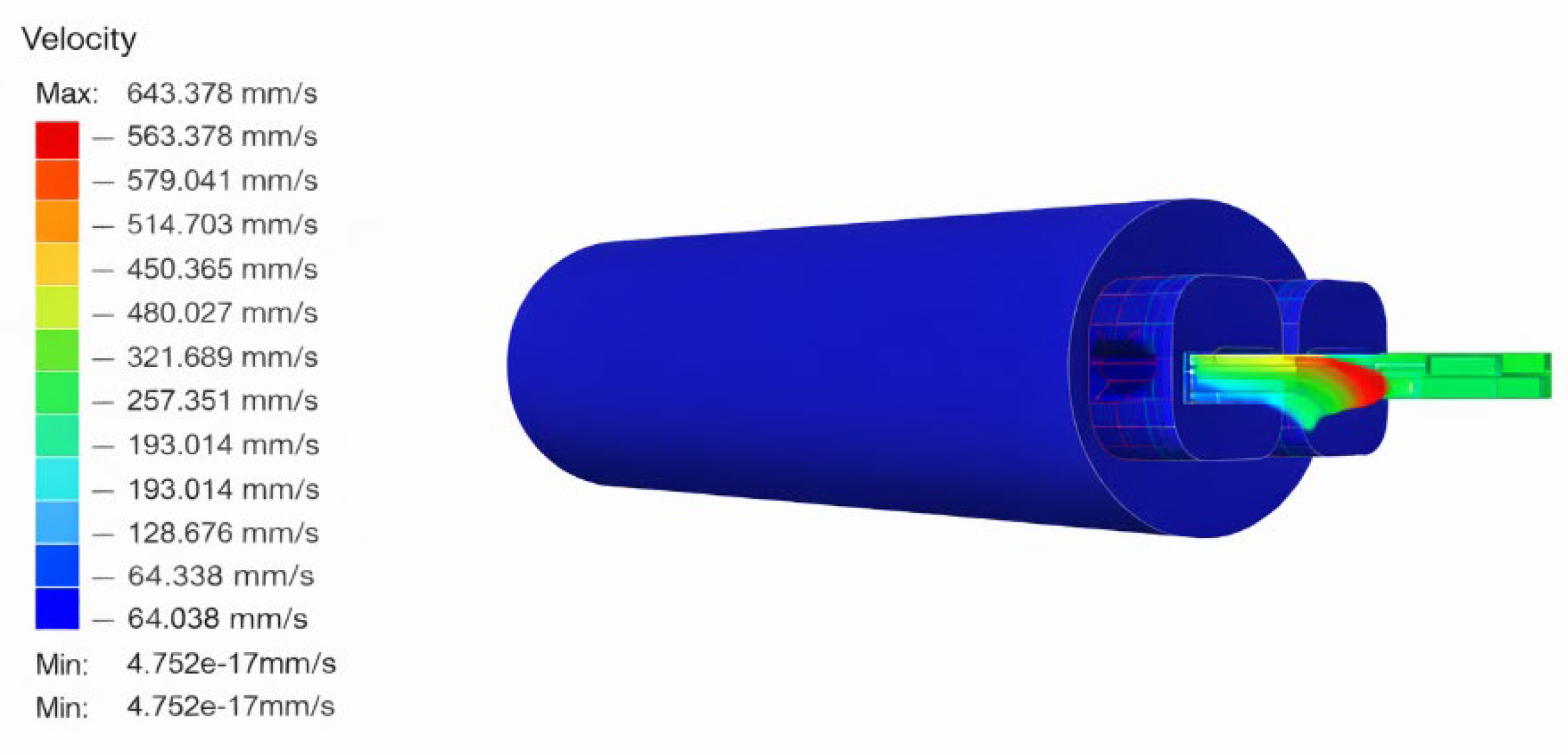
Figure 11.
Temperature contours.
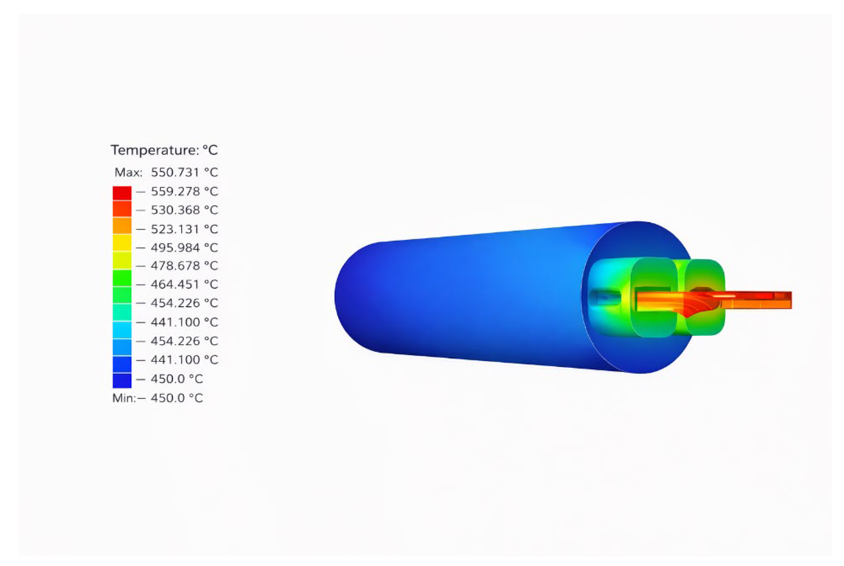
Figure 12.
Profile shape predictions and information provided by Altair Inspire Extrude Metal Software.
Figure 12.
Profile shape predictions and information provided by Altair Inspire Extrude Metal Software.
Concerning the finite element analysis meshing features of software and reasonable accuracies in order to track the nonlinear procedure by means of incremental-iterative procedure has been used. It should be noted that the billet, despite having larger volume, has less elements in comparison with the elements and the volume of the pockets. This is a reasonable feature of the FEM software.
4. Discussion
Profile A produced highly uniform pressure and velocity distributions, validating the effectiveness of the simple geometry in promoting balanced flow.
Profile B, exhibited significant flow imbalance (±70% at exit) owing to the bearing modification. This supports findings that even minor geometric variations in bearing and mandrel regions can substantially affect flow behavior.
This reinforces the principle that die bearing geometry dominates flow uniformity, a key design insight frequently noted in aluminum extrusion literature.
While both profiles fell within typical industrial load ranges, Profile B’s load distribution was less uniform and showed higher local peaks.
The threefold increase in maximum exit velocity for Profile B (≈643 mm/s) compared to Profile A (≈198 mm/s) underscores how bearing alterations accelerate material flow in specific paths, creating imbalances.
This behavior is consistent with simulation studies of aluminum extrusion, which state that velocity non-uniformity is a major source of defects (profile distortion, weld seam weaknesses) and is influenced by die geometry and process parameters (e.g., ram speed, billet temperature).
Both profiles achieved acceptable temperature ranges (close to 450-580 °C) for the alloy type, but Profile B showed larger surface temperature variation (~2.9%) vs Profile A (~1.4%).
This confirms that geometric imbalances (flow differences) translate into thermal imbalances, which eventually may affect metallurgical and surface quality.
Beyond refined computational modelling techniques, future investigation may use computational data produced by a suitable parametric investigation in order to train an artificial neural network and provide a Reduced Order Model based on Artificial Intelligence (ROM-AI) that predicts results quickly, in the sense of a Digital Twin, see e.g. [15].
Author Contributions
Conceptualization, D.S. and G.E.S.; methodology, D.S.; software, D.S.; validation, D.S. and G.E.S.; formal analysis, D.S.; investigation, D.S.; writing—original draft preparation, D.S.; writing—review and editing, D.S. and G.E.S..; visualization, D.S.; supervision, G.E.S.
Funding
This research received no external funding.
Data Availability Statement
Data will be provided by the first author after justified request.
Acknowledgments
The authors would like to sincerely thank Panagiotis Tounis, CEO of MATREX Extrusion Dies (Thessaloniki, Greece), for providing the industrial drawings and technical information used in this work. The industrial drawings were provided by MATREX Extrusion Dies with permission for academic use and public dissemination. Their contribution was invaluable in enabling the realistic modeling and analysis of industrial aluminum extrusion dies for academic research purposes. The numerical simulations presented in this thesis were performed using Altair Inspire Extrude Metal, which was accessed through Altair Engineering’s official student licensing program. We gratefully acknowledge Altair Engineering for providing free academic access to advanced simulation tools that support education and research in metal forming and manufacturing processes.
Conflicts of Interest
The authors declare no conflicts of interest.
References
- Laue, K. Extrusion: Processes, Machinery, Tooling. American Society for Metals, Metals Park,1981.
- Altan, T.; Oh, S.I.; Gegel, H.L. Metal Forming: Fundamentals and Applications. American Society for Metals, Metals Park, 1983.
- Qamar, S. Z. Modelling and Analysis of Aluminum Extrusion. LAP Lambert Academic Publishing, 211.
- Aluminum Extruders Council: Al.AEC, Aluminum Extrusion Counsil, 2018.
- ASM International, Aluminum Extrusion Technology. ASM Handbook, 1999.
- Sheppard, T., Extrusion of Aluminium Alloys. Springer, 1999.
- Ma, X. Surface quality of aluminum extrusion products, PhD Thesis. University of Twente, Enschede, Netherlands 2011.
- Qamar, S. Z.; Arif, A. F. M.; Sheikh, A. K. An investigation of shape complexity in metal extrusion. In Proceedings of the International Conference on Advances in Materials and Processing Technologies AMPT, Dublin, Ireland, July 8–11; 2003; pp. 1178–1183. [Google Scholar]
- Qamar, S.Z.; Sheikh, A.K.; Arif, A.F.M.; Pervez, T. Defining shape complexity of extrusion dies: a reliabilistic view. Mater. Manuf. Processes 2007, 22(7), 804–810. [Google Scholar] [CrossRef]
- Wang, Y; Wells, MA. The Effect of the Bridge’s Angle during Porthole Die Extrusion of Aluminum AA6082. Metals 2023, 13(3), 605. [Google Scholar] [CrossRef]
- Truong, T-T; Hsu, Q-C; Tong, V-C. Effects of Solid Die Types in Complex and Large-Scale Aluminum Profile Extrusion. Applied Sciences 2020, 10(1), 263. [Google Scholar] [CrossRef]
- Hovden, S.; Kronsteiner, J.; Arnold, J.A. Parameter study of extrusion simulation and grain structure prediction for 6xxx alloys with varied Fe content. Materials Today Communicatios 2024, 38, 108128. [Google Scholar] [CrossRef]
- Saha, S. C.; Kumar, S. Finite Element Simulation of Aluminum Extrusion Process: A Review. International Journal of Material Forming 2011, 4(2), 157–174. [Google Scholar]
- Rens, *!!! REPLACE !!!*; van, B. J. E. Finite element simulation of the aluminum extrusion process : shape prediction for complex profiles. Phd Thesis, TU/e Mechanical Engineering, Technische Universiteit Eindhoven, 1999. [CrossRef]
- Spathopoulos, S.C.; Stavroulakis, G.E. Springback Prediction in Sheet Metal Forming, Based on Finite Element Analysis and Artificial Neural Network Approach. Appl. Mech. 2020, 1, 97–110. [Google Scholar] [CrossRef]
Figure 1.
Extrusion Press Schematic.
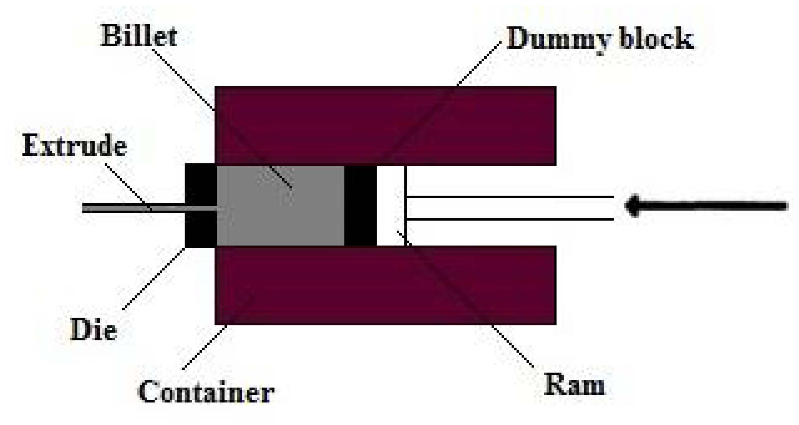
Figure 2.
Geometrical Die Features of extruded profile.
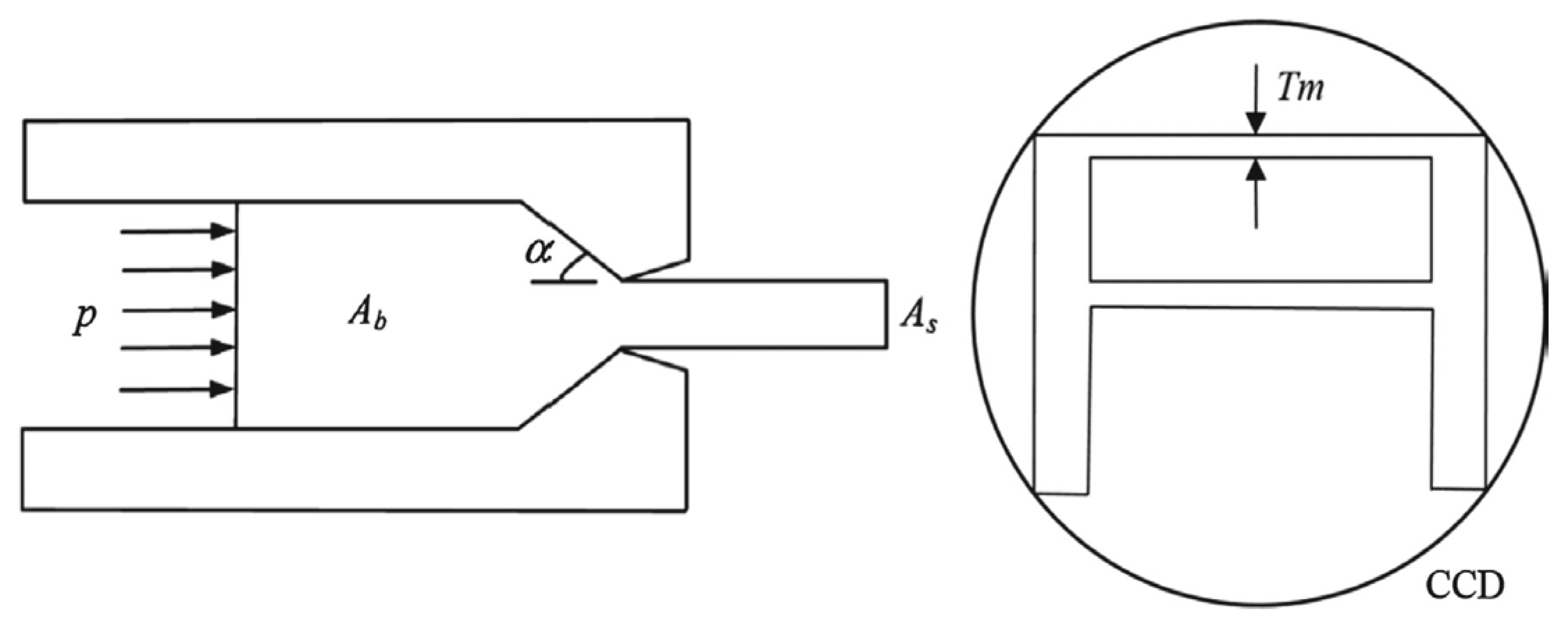
Figure 3.
Model of the single cavity die.
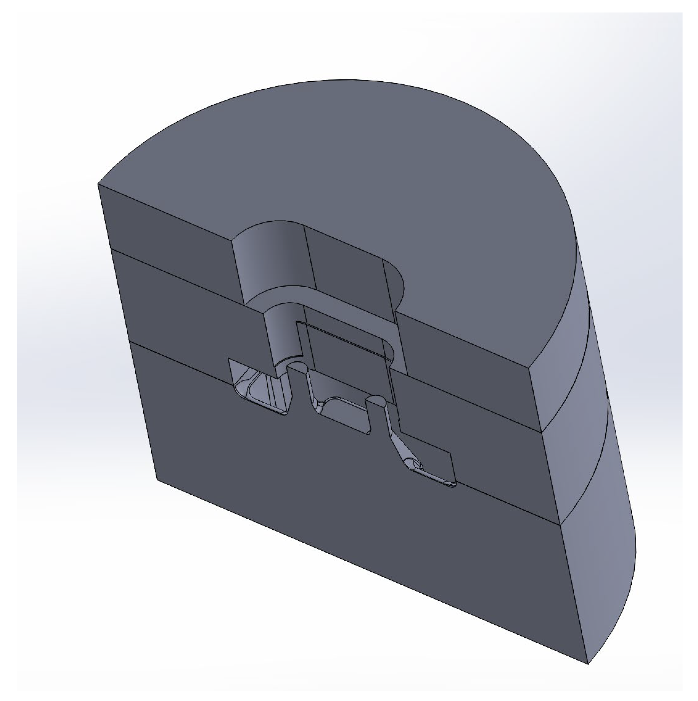
Figure 4.
Model of the dual cavity die.
Disclaimer/Publisher’s Note: The statements, opinions and data contained in all publications are solely those of the individual author(s) and contributor(s) and not of MDPI and/or the editor(s). MDPI and/or the editor(s) disclaim responsibility for any injury to people or property resulting from any ideas, methods, instructions or products referred to in the content. |
© 2026 by the authors. Licensee MDPI, Basel, Switzerland. This article is an open access article distributed under the terms and conditions of the Creative Commons Attribution (CC BY) license (http://creativecommons.org/licenses/by/4.0/).
Copyright: This open access article is published under a Creative Commons CC BY 4.0 license, which permit the free download, distribution, and reuse, provided that the author and preprint are cited in any reuse.


