
Submitted:
02 February 2026
Posted:
05 February 2026
You are already at the latest version
Abstract
Fast and universal grasping remains a critical challenge for robotic hands operating in unstructured and industrial environments. Conventional pin-array-based robotic hands exhibit strong adaptability to objects with diverse geometries, yet their grasping speed is often limited by centralized motor-driven actuation. To address this limitation, this paper presents the development of a fast-acting cluster-tube self-adaptive robotic hand (CTSA-FA hand), which transforms traditional active actuation into a passive energy-storage-and-release-driven grasping mechanism. A spring-cam-based structure is introduced to enable rapid energy release during the grasping phase, significantly reducing the gathering time. A theoretical model of the CTSA-FA hand is established, including cam trajectory planning and mechanical analysis, to guide parameter design and performance optimization. A physical prototype is developed and experimentally validated. Experimental results demonstrate that the proposed CTSA-FA hand can complete approximately three grasp-release cycles per second, corresponding to a grasping time of about 0.25~s per cycle, while maintaining robust adaptive grasping performance. These characteristics indicate that the proposed design is well suited for applications requiring fast and universal grasping, particularly in intelligent mining equipment and industrial automation scenarios.
Keywords:
robotic hand
; pin-array gripper
; fast grasping
; intelligent mining equipment
; adaptive grasping
1. Introduction
Robotic hands capable of universal and adaptive grasping have attracted increasing attention due to their broad potential in unstructured environments and automated production lines [1,2,3]. A persistent challenge in robotic grasping lies in achieving both strong adaptability to diverse object geometries and high grasping speed. Many existing robotic hands rely on complex mechanical structures or centralized actuation mechanisms to realize adaptability, which often results in limited dynamic response and slow closing motions. This inherent trade-off between adaptability and grasping speed significantly constrains the deployment of robotic hands in fast-paced manipulation tasks, particularly in intelligent mining equipment, where grasping systems are required to operate reliably under harsh conditions, limited perception, and strict efficiency demands.
Humanoid multi-fingered robotic hands are designed to emulate the anatomical structure and functional dexterity of the human hand. Representative examples include dexterous hands such as the Shadow Dexterous Hand [4], the Optimus hand [5], and other high-degree-of-freedom platforms [6]. Equipped with a large number of actuators and degrees of freedom (DOFs), these hands are capable of complex postures and manipulation behaviors. However, the high mechanical complexity and sophisticated control strategies required by such designs result in elevated manufacturing costs, increased control burden, and limited operational efficiency, particularly in applications where rapid and repetitive grasping is required. To mitigate these drawbacks, underactuated robotic hands [7,8] have been proposed to reduce the number of actuators while retaining adaptive grasping capability, including the iHY hand [9], the Robotiq hand [10], and the TH-I hand [11]. Although underactuated designs simplify control through mechanical coupling, their grasping speed and adaptability remain constrained by transmission mechanisms and motor-driven actuation.
To overcome the limitations associated with humanoid hands, a wide range of specialized robotic grippers have been developed with an emphasis on grasping robustness, universality, and operational efficiency. Unlike humanoid hands, these grippers typically do not rely on finger-like structures; instead, they achieve stable grasping across diverse object geometries through innovative mechanical designs, often without requiring precise perception of object shape and pose. Representative examples include the universal gripper based on granular jamming activated by vacuum suction [12,13], universal jamming gripper [14], woven soft wrist-gripper [15], grippers inspired by biological mechanisms such as the chameleon tongue [16], as well as spherical adaptive grippers including Tsinghua University’s SSA gripper [17]. These designs demonstrate that mechanical adaptability can be achieved through non-anthropomorphic structures, providing reliable grasping performance with simplified control.
Among specialized grippers, pin-array-based designs have attracted particular attention due to their inherent geometric adaptability and mechanical simplicity [18,19]. By employing spatially distributed contact elements that can independently conform to object surfaces, pin-array mechanisms are capable of achieving universal grasping across objects with diverse shapes and sizes. A representative example is the Omnigripper [18], which demonstrates that pin-array structures can provide reliable and rigid contact while maintaining strong adaptability. These characteristics make pin-array-based mechanisms a promising solution for robust and universal grasping.
Building upon the pin-array adaptation principle, numerous robotic hands and tools have been developed to further enhance grasping versatility, including designs that realize universal grasping through frictional and prismatic mechanisms [20], balloon-based adaptation [21], as well as meshing [22], bending [23], and rotational mechanisms [24]. These studies collectively validate the effectiveness of pin-array-based mechanisms for adaptive grasping and highlight their potential for deployment in a wide range of robotic applications.
Despite their strong adaptability, pin-array-based robotic hands are often limited by slow grasping speed. This limitation primarily arises from centralized actuation schemes in which a single motor or actuator drives the simultaneous motion of a large number of adaptive elements. The cluster-tube self-adaptive (CTSA) hand [24] exemplifies this issue. Although increasing motor speed can partially accelerate the grasping process, such an approach inevitably results in higher power consumption and reduced energy efficiency, thereby limiting practical applicability in scenarios that require rapid grasping.
In this work, fast grasping is defined as a substantially reduced closing time compared with conventional centralized-actuation pin-array grippers, achieved through rapid energy release rather than continuous motor-driven transmission. To address the speed limitation of pin-array-based robotic hands, this paper presents the development of a fast-acting cluster-tube self-adaptive robotic hand (CTSA-FA hand). The proposed design transforms conventional active actuation into an energy-storage-and-release-driven mechanism enabled by a spring–cam-based structure. Key design parameters are systematically determined through theoretical analysis, and a physical prototype is developed. Experimental results demonstrate that the proposed CTSA-FA hand can achieve rapid grasping with a closing time of approximately 0.25 s per grasp, indicating its strong potential for applications requiring fast and efficient object acquisition.
2. Design and Working Principle of the CTSA-FA Hand
2.1. Design Concept and Actuation Strategy
In the original cluster-tube self-adaptive (CTSA) hand, the lateral convergence of all sliding tube assemblies is realized through a tendon-driven centralized actuation mechanism. In such a configuration, increasing the grasping speed mainly relies on modifying the transmission ratio or selecting a higher-speed motor, which inevitably leads to a reduction in grasping force under the same power constraint. This trade-off limits the applicability of the CTSA hand in scenarios requiring rapid object acquisition.
To overcome this limitation, this study proposes a fast-acting cluster-tube self-adaptive hand (CTSA-FA) by fundamentally rethinking the actuation strategy. Instead of directly driving the lateral convergence using the motor, the proposed design converts active motor actuation into an energy storage and release mechanism. Inspired by energy-driven mechanical devices, elastic energy is pre-stored and instantaneously released to achieve rapid grasping, thereby decoupling grasping speed from motor power.
Based on this concept, the CTSA-FA hand adopts the actuation scheme illustrated in Figure 1(a), enabling fast lateral convergence while maintaining sufficient grasping force.
2.2. Mechanical Structure and Component Description
The overall mechanical structure of the CTSA-FA hand is shown in Figure 2, and the exploded view is presented in Figure 2(c). The CTSA-FA hand mainly consists of a base, multiple sliding tube assemblies arranged in an array, a motor, a cam mechanism, and a grip applicator.
Each sliding tube assembly comprises a base connector, a guided rod, a sliding tube, a compression spring, a soft skin, and a soft contactor. The guided rod is articulated to the base through a rotating shaft, allowing the assembly to swing only in the radial direction. The sliding tube is mounted on the guided rod and can translate axially along it. The sliding tube moves axially along the guided rod, and a compression spring is installed between the sliding tube and the guided rod to provide automatic axial reset after grasping.
All sliding tube assemblies are distributed circumferentially along the base. Mechanical constraints are introduced to ensure that each assembly can only swing radially inward or outward. The grip applicator is arranged in an independent cavity within the base and mechanically couples all sliding tube assemblies, enabling the application of uniform lateral grasping force.
A cam mechanism is employed to coordinate the grasping, release, and energy re-storage processes, as shown in Figure 2(b). The cam profile is specifically designed such that different phases of a single rotational cycle correspond to lateral convergence, forced release, and elastic energy re-storage. The cam is directly driven by the motor, allowing precise control of the grasping and releasing states through continuous motor rotation without the need for motor reversal.
The working process of the CTSA-FA hand is illustrated in Figure 3 and can be divided into three sequential stages: vertical adaptation, fast lateral convergence, and release with energy re-storage.
2.3. Grasping and Release Process
2.3.1. Vertical Adaptive Grasping
The CTSA-FA hand approaches the target object vertically under the motion of the robotic arm. When a sliding tube assembly contacts the object, the corresponding sliding tube moves axially along the guided rod. As a result, different sliding tubes adjust their axial positions according to the object’s surface profile, enabling passive vertical self-adaptation.
2.3.2. Fast lateral Convergence
After vertical adaptation, the motor drives the cam to rotate to the grasping phase. In this phase, the constraint on the grip applicator is instantaneously released, allowing the elastic energy stored in the energy storage spring to be rapidly released. Consequently, all sliding tube assemblies converge toward the center at high speed. When a sliding tube contacts the object during convergence, its motion stops and a grasping force is exerted. Through this process, lateral self-adaptation and stable grasping are achieved simultaneously.
2.3.3. Release and Reset
To release the object, the motor continues to rotate in the same direction, driving the cam into the release phase. In this phase, the cam actively pushes the sliding tube assemblies outward in the radial direction, forcing them back to the upright configuration. During this motion, the grip applicator is re-tensioned, and elastic energy is stored again in the grip applicator. Once the sliding tubes lose contact with the object, the axial reset springs drive the sliding tubes back to their extended positions along the guided rods, completing the vertical reset.
Through the above process, the CTSA-FA hand realizes spatially discrete adaptive grasping with a fast-acting mechanism. By combining pin-array adaptability with energy-driven lateral convergence, the proposed hand achieves high grasping speed while maintaining sufficient grasping force, making it suitable for robotic applications that require rapid and reliable grasping.
3. Theoretical Analysis and Parameter Design
This section presents the theoretical analysis and parameter design of the proposed CTSA-FA hand. The analysis focuses on two aspects: (i) cam trajectory design for fast state switching with favorable mechanical characteristics, and (ii) force and torque modeling for motor selection and grasping force evaluation. The purpose of the following analysis is not to pursue a closed-form solution, but to reveal the influence of key geometric and mechanical parameters on the grasping behavior, thereby guiding the practical design of the CTSA-FA hand.
3.1. Cam Trajectory Design
According to the operating principle described in Section II, the cam drives multiple sliding tube assemblies arranged uniformly along the circumferential direction, the cam profile is shown in Figure 4. Let n denote the number of sliding tube assemblies. The cam profile can therefore be divided into n identical angular units, and the angular span of a single unit is defined as
Within each unit, the cam motion consists of two consecutive phases: a fast grasping phase and a release/reset phase. Let denote the angular proportion of the grasping phase within one unit. The corresponding angular spans of the grasping and release phases are then given by
The cam profile is formulated in polar coordinates. Let denote the radial distance from the cam center to the contact point with the sliding tube assembly. To ensure smooth motion and stable grasping and release states, the cam trajectory must satisfy the following boundary conditions:
In this paper, the cam curve is solved in the form of polar coordinates. Let the motion trajectory function of the sliding tube assembly relative to the cam in the grabbing section be and the motion trajectory function of the sliding tube assembly relative to the cam in the releasing process be . According to the structural design in Chapter 2, these functions should satisfy
and
By enforcing the above constraints and adopting a fourth-order polynomial form for each phase, the cam trajectory can be expressed as
This trajectory ensures zero velocity at the beginning and end of each phase, reducing impact, vibration, and mechanical wear during fast switching.
For cam manufacturability, the outer cam profile is obtained as the envelope of the inner tangents of circular pin sections arranged along the trajectory defined by . In the subsequent mechanical analysis, only the trajectory function is required.
3.2. Pseudo-Pressure Angle Analysis
The pressure angle between the cam and a sliding tube assembly is a key factor affecting transmission efficiency and mechanical reliability. Based on cam mechanism theory, the instantaneous pressure angle can be expressed as
During the grasping and release phases, the relative motion directions between the cam and the sliding tube assemblies are opposite. To facilitate unified mechanical analysis, a pseudo-pressure angle is defined as
When , a smaller pressure angle reduces transmission losses; when , a pressure angle closer to zero mitigates adverse loading on the motor and cam. Therefore, minimizing both the magnitude and fluctuation of is beneficial for system durability and efficiency.
Figure 5 illustrates the variation of within a single cam unit. In this study, sliding tube assemblies are used, resulting in . Parametric analysis indicates that increasing reduces the maximum pseudo-pressure angle, while excessively small may lead to undercutting and unfavorable geometry. Considering both fast grasping performance and mechanical safety, and are selected.
3.3. Mechanical Model and Force Analysis
A mechanical model of a single sliding tube assembly is established, as shown in Figure 6. Let denote the normal contact force between the cam and the sliding tube assembly, and the corresponding friction coefficient. The grip applicator exerts a lateral force on the sliding tube assembly through a lever mechanism.
According to Hooke’s law, the force provided by the energy-storage spring in the grip applicator can be expressed as
where is the preload force, k is the spring stiffness, is the lever arm of the grip applicator, and
with denoting the cam contact lever arm.
The geometric ratio
is introduced for compact representation.
Two operating cases are considered: state switching and object grasping.
3.3.1. Motor Torque Requirement
During state switching, the cam actively drives the sliding tube assemblies, while no object contact occurs. From static equilibrium, the motor torque required to rotate the cam is given by
where n is the number of sliding tube assemblies.
By substituting the force relations and geometric constraints, the torque expression can be rewritten as
Parametric studies based on this analytical expression are conducted to evaluate the influence of mechanical parameters () and geometric parameters (). The results, shown in Figs. Figure 7, Figure 8, Figure 9, Figure 10, indicate that the friction coefficient has a dominant effect on the peak motor torque, while the spring stiffness k has a relatively minor influence. Increasing generally reduces the required motor torque within a feasible geometric range.
3.3.2. Grasping Force Analysis
When grasping an object, the cam remains at its minimum radius and no longer contacts the sliding tube assemblies. Each sliding tube assembly can be in either a grasping state or an adaptive state.
For a sliding tube assembly in the grasping state, the normal grasping force exerted on the object is
where is the contact lever arm.
For an assembly in the adaptive state, the vertical compliance force is
where is the stiffness of the vertical reset spring and is the axial displacement.
The maximum lifting force provided by the CTSA-FA hand can then be expressed as
where and denote the numbers of sliding tube assemblies in the grasping and adaptive states, respectively, and is the friction coefficient between the sliding tube surface and the object.
This expression indicates that larger , smaller , higher , and larger contribute to increased grasping force. However, excessive reduces vertical adaptability, highlighting the trade-off between grasping strength and adaptability.
This analysis provides a quantitative basis for parameter selection and cam profile design, rather than serving as an exhaustive dynamic model.
4. Experiments
For clarity, the grasping speed evaluated in this section focuses on the mechanical closing duration of the hand, which is the critical bottleneck for pin-array grippers relying on centralized actuation.
Based on the mechanical design described in Section II and the theoretical analysis in Section III, a prototype of the proposed CTSA-FA hand was fabricated, as shown in Figure 11. The prototype has a total mass of 612 g, a maximum height of 245 mm, and a maximum outer diameter of 75 mm.
A series of experiments were conducted to evaluate the performance of the CTSA-FA hand, with particular emphasis on fast grasping capability and adaptive grasping performance.
4.1. Fast Grasping Performance
To evaluate the grasping speed, the grasping and releasing process of the CTSA-FA hand was recorded using a camera. The corresponding video is provided as Supplementary Video S1. By frame-by-frame analysis of the recorded video, it is observed that the CTSA-FA hand is capable of completing three full grasp–release cycles within one second.
This result indicates that the average time required for a single grasping action is approximately 0.25 s. Such a grasping speed is significantly faster than that of conventional pin-array-based robotic hands, demonstrating the effectiveness of the proposed energy-storage-and-release driving strategy for rapid state switching.
4.2. Adaptive Grasping Experiments
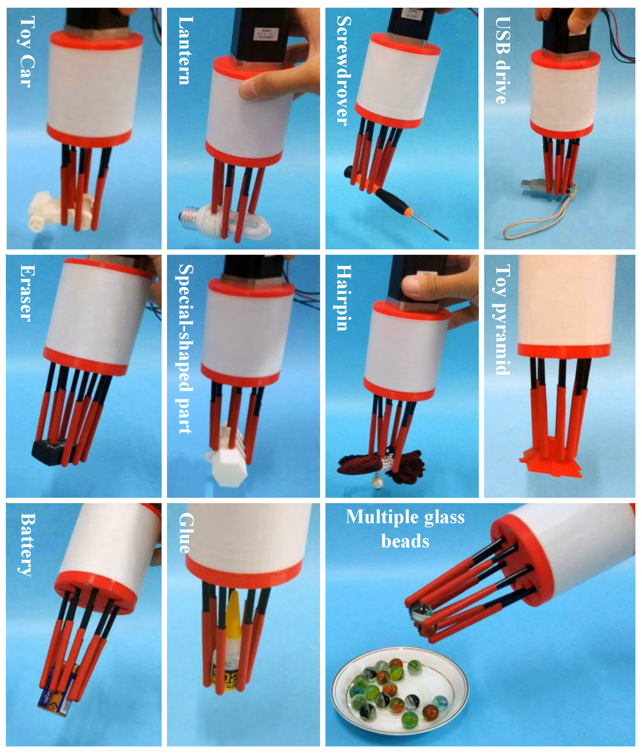
To assess the adaptive grasping capability, the CTSA-FA hand was tested on objects with various sizes, shapes, and surface materials. Representative experimental results are shown in Figure 12, and additional demonstrations are provided in Supplementary Video S1.
During the experiments, the sliding tube assemblies were observed to adapt automatically to the object contours in the vertical direction, followed by rapid lateral convergence to achieve stable grasping. The CTSA-FA hand successfully grasped objects with irregular geometries and different orientations without requiring prior knowledge of object shape or pose.
4.3. Discussion
The experimental results demonstrate that the proposed CTSA-FA hand achieves both fast grasping and robust adaptive grasping. The grasping process is simple to control and exhibits stable and repeatable behavior.
Compared with conventional pin-array grippers, the proposed CTSA-FA hand is particularly suitable for scenarios requiring rapid object acquisition, such as sorting and pick-and-place tasks on production lines.
5. Conclusions
In this study, the development of a fast-acting cluster-tube self-adaptive robotic hand is presented. By introducing an energy-driven grasping strategy based on stored elastic energy and rapid release, the proposed CTSA-FA hand effectively overcomes the limitation of low grasping speed commonly observed in conventional pin-array robotic hands. A systematic mechanical design and theoretical analysis are conducted to support the development of the prototype and guide parameter selection. Experimental results demonstrate that the CTSA-FA hand achieves fast and reliable adaptive grasping, validating the effectiveness of the proposed design. Future work will focus on integrating perception modules and exploring modular design strategies to further enhance the autonomy and applicability of the CTSA-FA hand in practical robotic systems.
Supplementary Materials
The following supporting information can be downloaded at website of this paper posted on Preprints.org, Video S1: High-speed grasping and adaptive grasping experiments of the CTSA-FA hand.
Author Contributions
Conceptualization, H.F. and W.Z.; methodology, H.F.; theoretical analysis, H.F.; design and prototype development, H.F.; experiments, H.F.; data analysis, H.F.; writing—original draft preparation, H.F.; writing—review and editing, W.Z. and H.F.; supervision, W.Z.; project administration, H.C., D.X. and Q.W.; resources, H.C., D.X. and Q.W. All authors have read and agreed to the published version of the manuscript.
Funding
This work is supported by the China Postdoctoral Science Foundation - CCTEG Joint Support Program (Grant No. 2025T028ZGMK), the Natural Science Foundation of Chongqing Municipality (Grant No. CSTB2023NSCQ-MSX0612), and the Chongqing Postdoctoral Special Support Program (Grant No. 2024CQBSHTB3023).
Institutional Review Board Statement
Not applicable.
Informed Consent Statement
Not applicable.
Data Availability Statement
The data supporting the findings of this study are available from the corresponding author upon reasonable request. Supplementary materials, including videos, are provided with this article.
Conflicts of Interest
The authors declare no conflicts of interest.
References
- Kim, C.H.; Silwal, A.; Kantor, G. Autonomous robotic pepper harvesting: Imitation learning in unstructured agricultural environments. IEEE Robotics and Automation Letters, 2025. [Google Scholar]
- Lee, D.; Nahrendra, I.M.A.; Oh, M.; Yu, B.; Myung, H. TRG-Planner: Traversal Risk Graph-Based Path Planning in Unstructured Environments for Safe and Efficient Navigation. IEEE Robotics and Automation Letters, 2025. [Google Scholar]
- Urrea, C. Adaptive Multi-Objective Reinforcement Learning for Real-Time Manufacturing Robot Control. Machines 2025, 13, 1148. [Google Scholar] [CrossRef]
- Li, S.; Ma, X.; Liang, H.; Görner, M.; Ruppel, P.; Fang, B.; Sun, F.; Zhang, J. Vision-based teleoperation of shadow dexterous hand using end-to-end deep neural network. In Proceedings of the 2019 International Conference on Robotics and Automation (ICRA), 2019; IEEE; pp. 416–422. [Google Scholar]
- Malik, A.A.; Masood, T.; Brem, A. Intelligent humanoid robots in manufacturing. In Proceedings of the Companion of the 2024 ACM/IEEE International Conference on Human-Robot Interaction, 2024; pp. 20–27. [Google Scholar]
- Zhang, J.; Zhao, H.; Chen, K.; Fei, G.; Li, X.; Wang, Y.; Yang, Z.; Zheng, S.; Liu, S.; Ding, H. Dexterous hand towards intelligent manufacturing: A review of technologies, trends, and potential applications. Robotics and Computer-Integrated Manufacturing 2025, 95, 103021. [Google Scholar] [CrossRef]
- Zhang, Y.; Xia, D.; Lu, Q.; Zhang, Q.; Wei, H.; Chen, W. Design, analysis and experimental research of dual-tendon-driven underactuated gripper. Machines 2022, 10, 761. [Google Scholar] [CrossRef]
- Liu, H.; Chen, Y.; Hu, Y.; Hu, Z.; Liu, J.; Huang, X.; Yao, S.; Wu, Y. Design and Experimental Research of an Underactuated Rigid–Flexible Coupling Mechanical Gripper. Machines 2025, 13, 1068. [Google Scholar] [CrossRef]
- Odhner, L.U.; Jentoft, L.P.; Claffee, M.R.; Corson, N.; Tenzer, Y.; Ma, R.R.; Buehler, M.; Kohout, R.; Howe, R.D.; Dollar, A.M. A compliant, underactuated hand for robust manipulation. The International Journal of Robotics Research 2014, 33, 736–752. [Google Scholar] [CrossRef]
- Sadun, A.S.; Jalani, J.; Jamil, F. Grasping analysis for a 3-finger adaptive robot gripper. In Proceedings of the 2016 2nd IEEE International Symposium on Robotics and Manufacturing Automation (ROMA), 2016; IEEE; pp. 1–6. [Google Scholar]
- Zhang, W.; Chen, Q.; Sun, Z.; Zhao, D. Under-actuated passive adaptive grasp humanoid robot hand with control of grasping force. Proceedings of the 2003 IEEE International Conference on Robotics and Automation (Cat. No. 03CH37422) 2003, Vol. 1, 696–701. [Google Scholar]
- Amend, J.R.; Brown, E.; Rodenberg, N.; Jaeger, H.M.; Lipson, H. A positive pressure universal gripper based on the jamming of granular material. IEEE transactions on robotics 2012, 28, 341–350. [Google Scholar] [CrossRef]
- Brown, E.; Rodenberg, N.; Amend, J.; Mozeika, A.; Steltz, E.; Zakin, M.R.; Lipson, H.; Jaeger, H.M. Universal robotic gripper based on the jamming of granular material. Proceedings of the National Academy of Sciences 2010, 107, 18809–18814. [Google Scholar] [CrossRef]
- de Rodrigo, I.; Belart, J.; Lopez-Lopez, A.J. Universal Jamming Gripper: Experimental Analysis on Envelope and Granular Materials. Machines 2024, 12, 52. [Google Scholar] [CrossRef]
- Zhou, P.; Liu, Y.; Chen, J.; Chen, H.; Li, H.; Yao, J. A Woven Soft Wrist-Gripper Composite End-Effector with Variable Stiffness: Design, Modeling, and Characterization. Machines 2025, 13, 1042. [Google Scholar] [CrossRef]
- Li, M.; Huang, X.; Liu, Q.; Yin, Z. A Variable Stiffness Bioinspired Swallowing Gripper Based on Particle Jamming. Soft Robotics 2025, 12, 56–67. [Google Scholar] [CrossRef] [PubMed]
- Zhu, T.; Yang, H.; Zhang, W. A spherical self-adaptive gripper with shrinking of an elastic membrane. In Proceedings of the 2016 International Conference on Advanced Robotics and Mechatronics (ICARM), 2016; IEEE; pp. 512–517. [Google Scholar]
- Scott, P.B. The ’Omnigripper’: A form of robot universal gripper. Robotica 1985, 3, 153–158. [Google Scholar] [CrossRef]
- Lee, L.Y.; Terrile, S.; Nam, S.; Liang, T.; Lepora, N.; Rossiter, J. Fin-A-rays: Expanding soft gripper compliance via discrete arrays of flexible structures. Soft Robotics, 2025. [Google Scholar]
- Lee, C.; Kim, H.; Oh, M.; Ok, K.; Ahn, S.H. Frictional and Prismatic Pin-Array Gripper for Universal Gripping and Stable Tool Manipulation. IEEE Transactions on Robotics 2025, 41, 6693–6706. [Google Scholar] [CrossRef]
- Kemmotsu, Y.; Tadakuma, K.; Abe, K.; Watanabe, M.; Tadokoro, S. Balloon pin-array gripper: two-step shape adaptation mechanism for stable grasping against object misalignment. IEEE Robotics and Automation Letters, 2024. [Google Scholar]
- Mo, A.; Zhang, W. A novel universal gripper based on meshed pin array. International journal of advanced robotic systems 2019, 16, 1729881419834781. [Google Scholar] [CrossRef]
- Fu, H.; Zhang, W. The development of a soft robot hand with pin-array structure. Applied Sciences 2019, 9, 1011. [Google Scholar] [CrossRef]
- Fu, H.; Yang, H.; Song, W.; Zhang, W. A novel cluster-tube self-adaptive robot hand. Robotics and biomimetics 2017, 4, 25. [Google Scholar] [CrossRef] [PubMed]
Figure 1.
Driving method of CTSA hand.
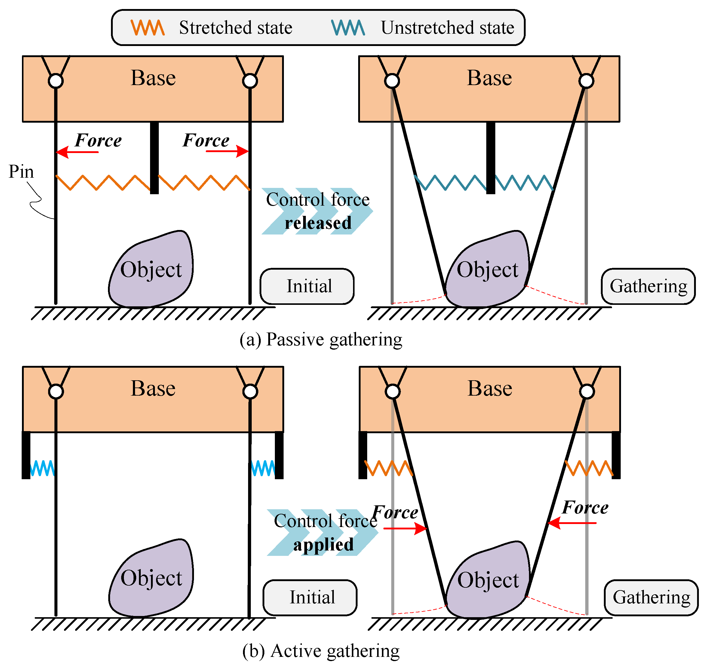
Figure 2.
The design of CTSA-FA hand.
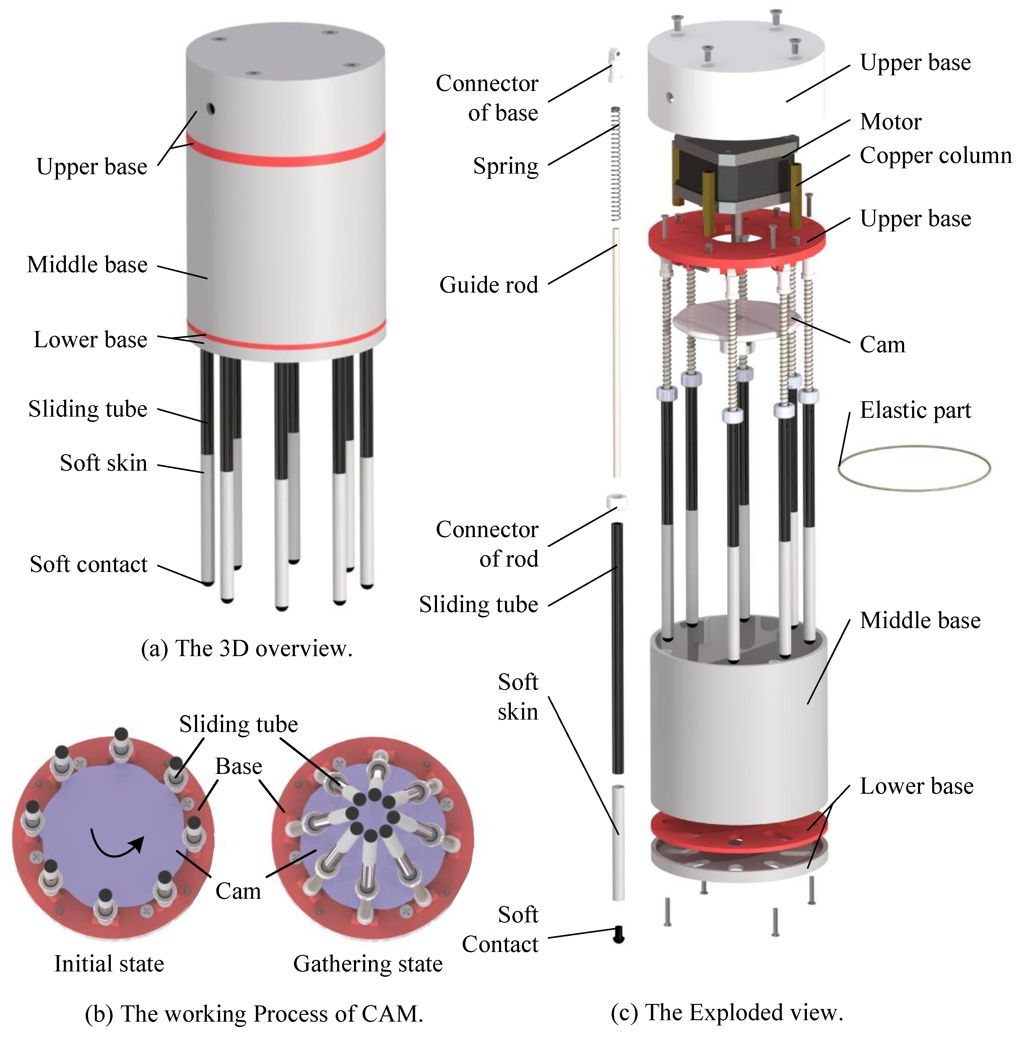
Figure 3.
The grasping process of CTSA-FA hand.
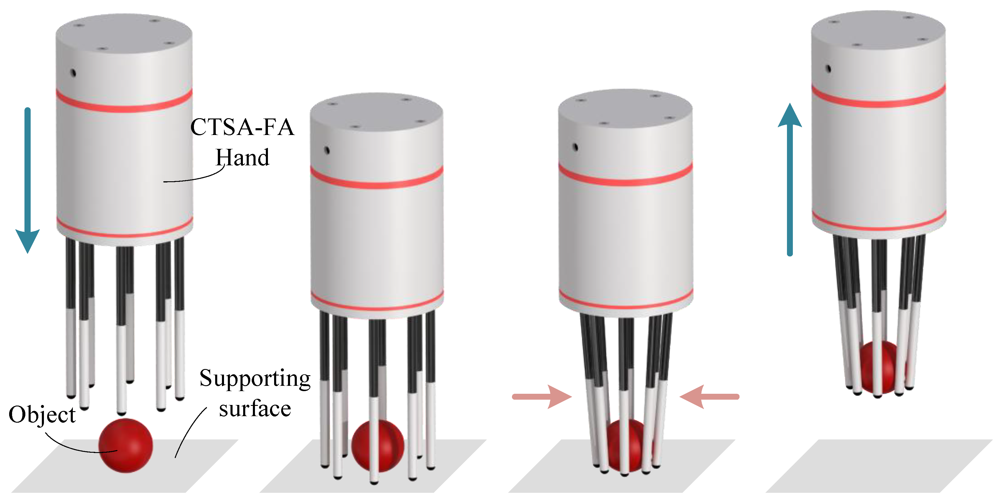
Figure 4.
Cam profile of the elastic-rope mechanism.
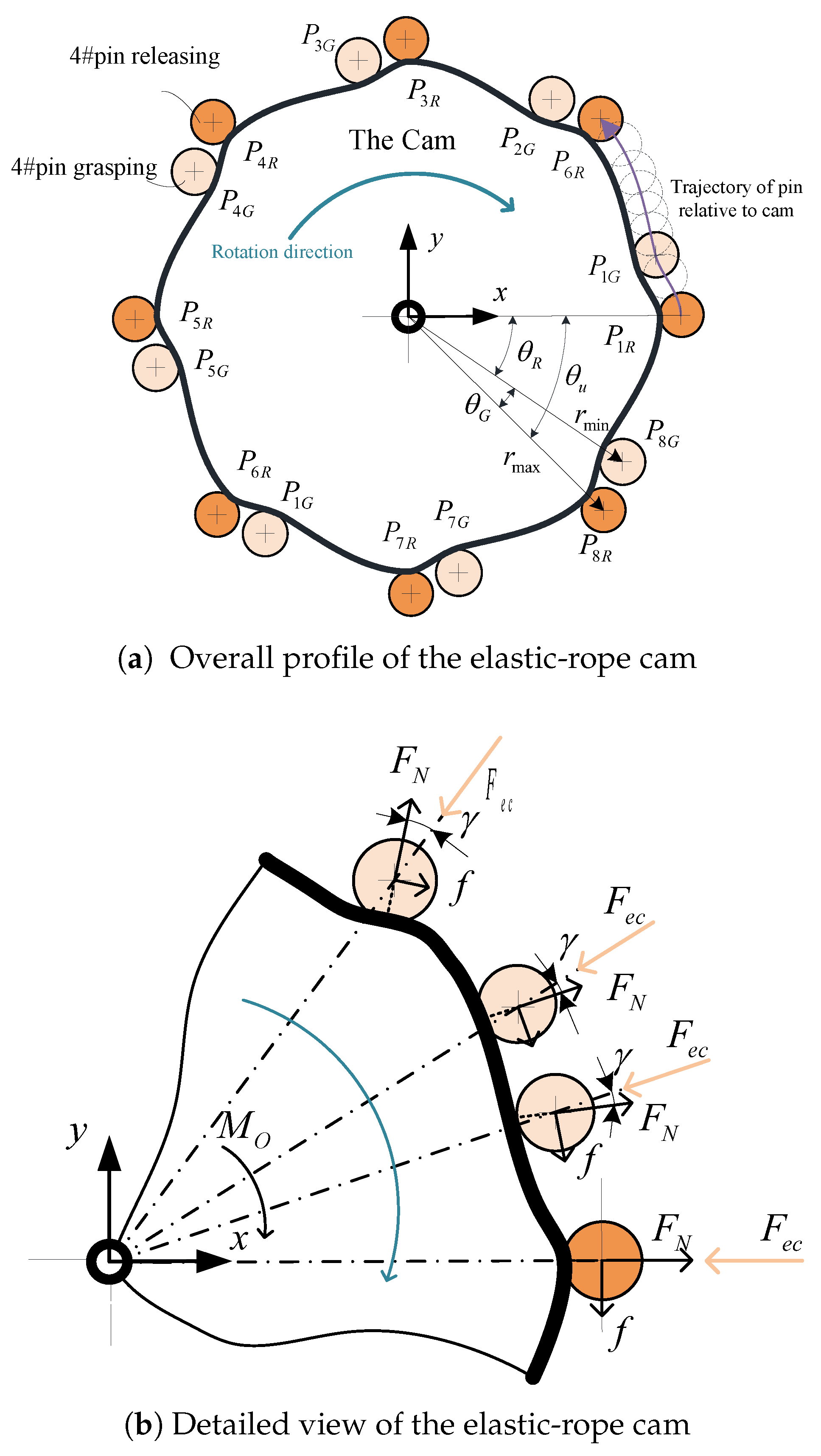
Figure 5.
Influence of design parameters on the pseudo-pressure angle.
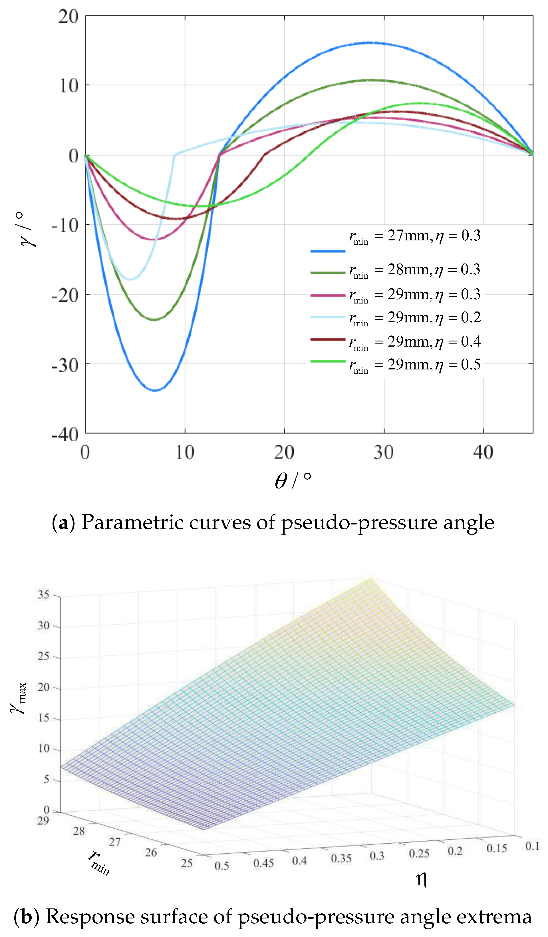
Figure 6.
Force model of a single sliding tube assembly.
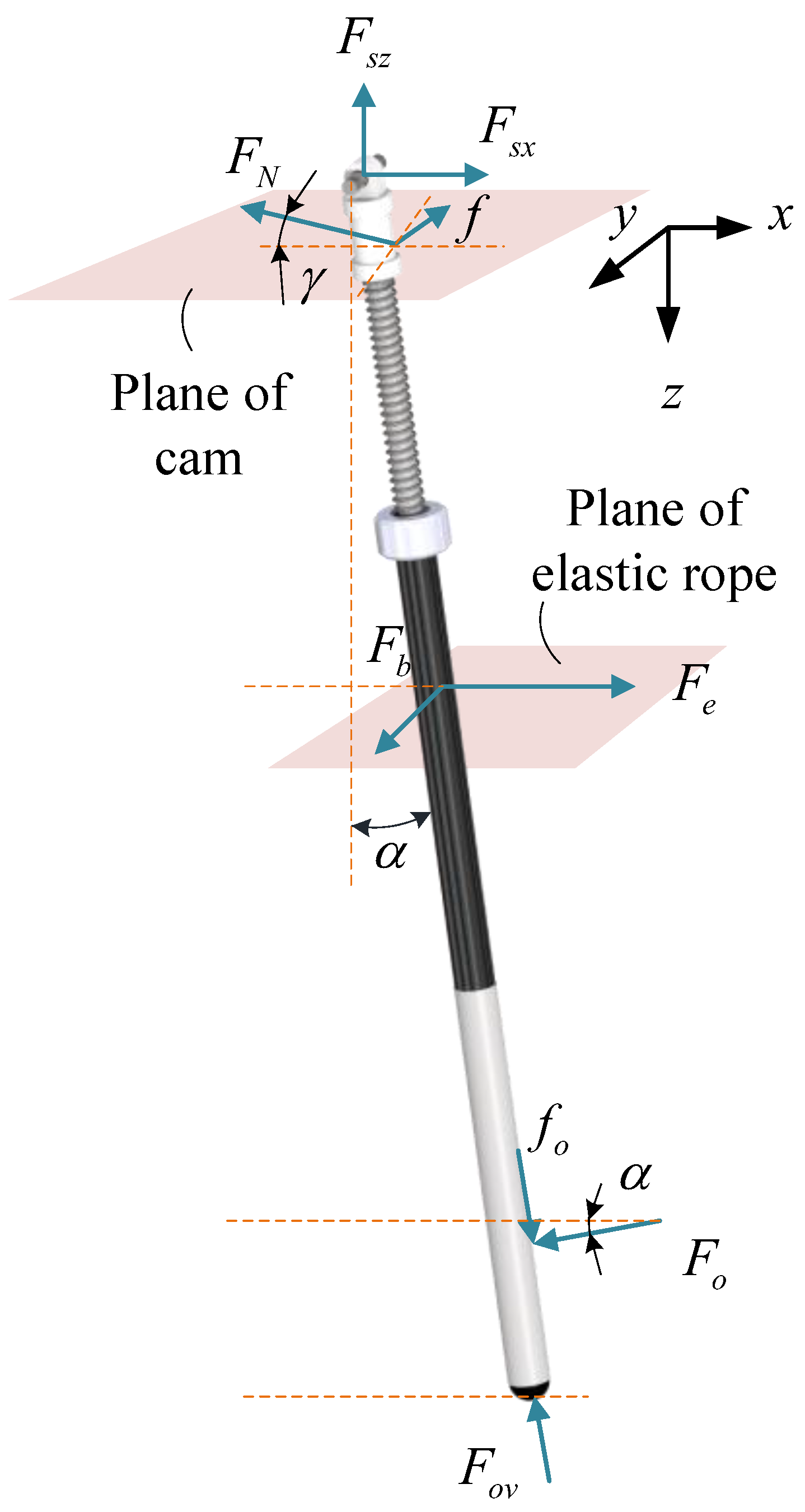
Figure 7.
The influence of k and on , where
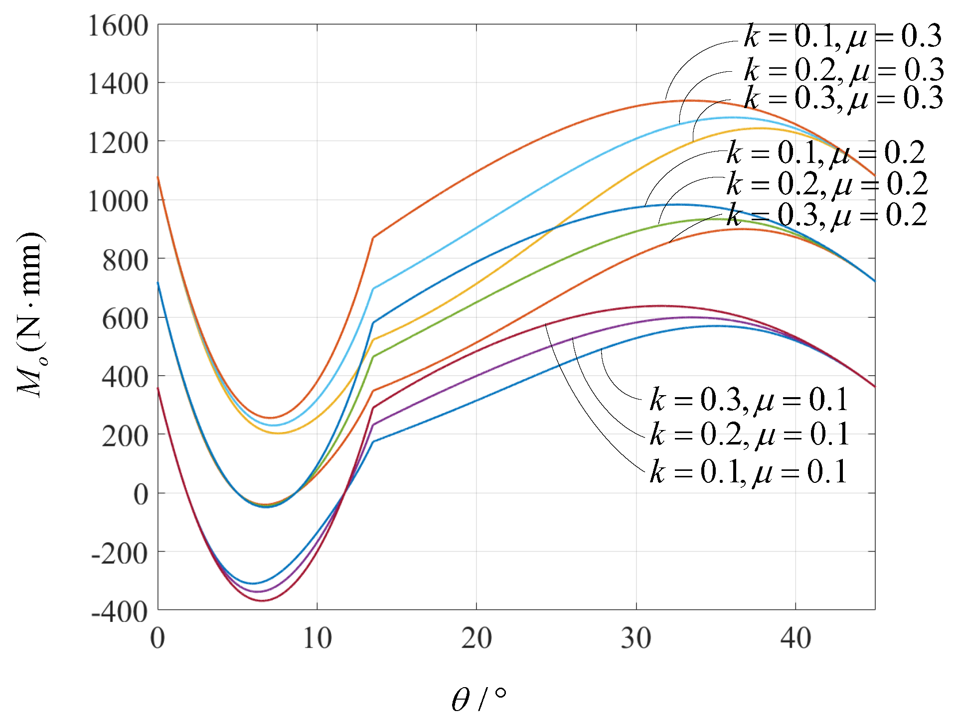
Figure 8.
The influence of k and on , where
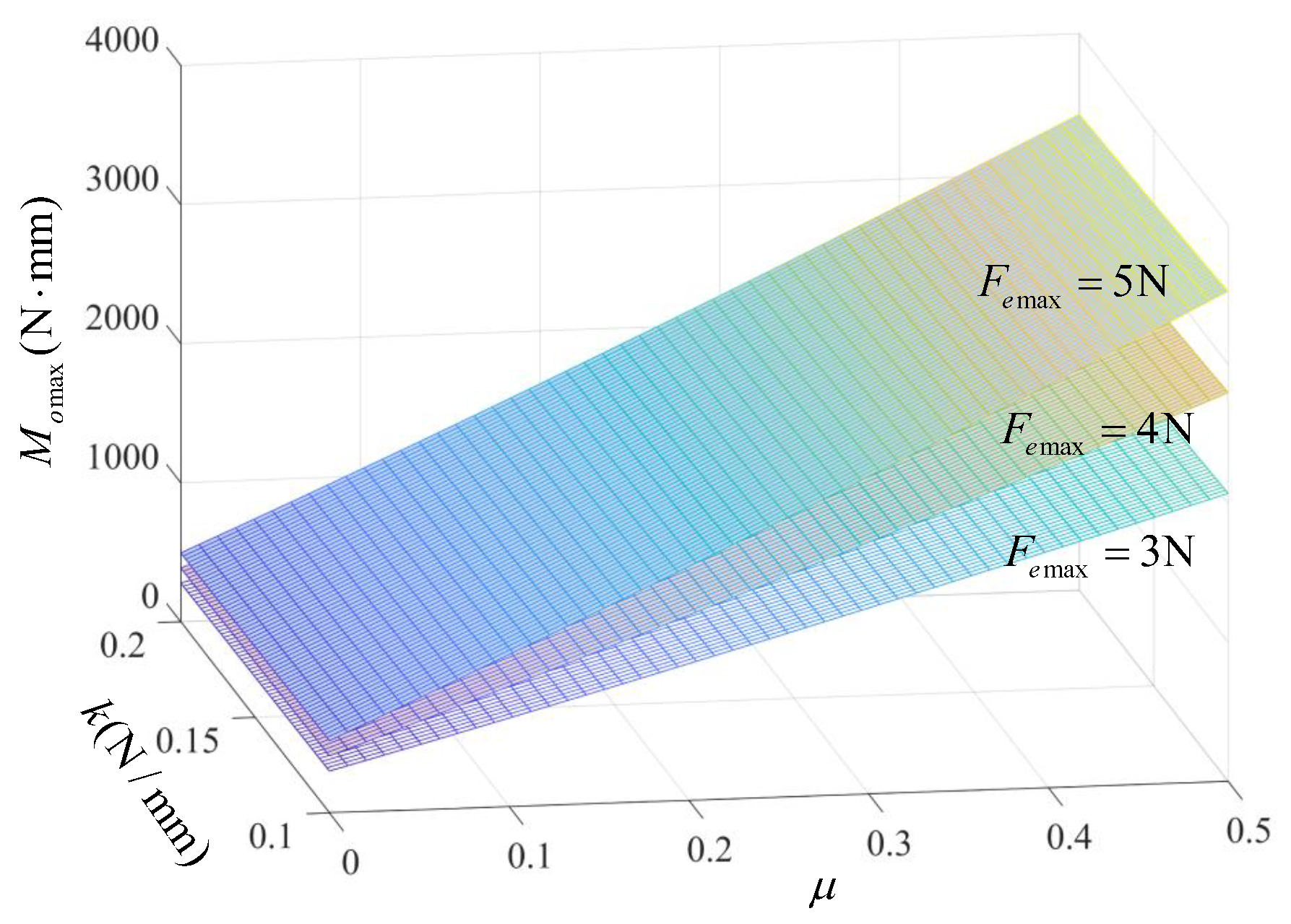
Figure 9.
The influence of and on , where
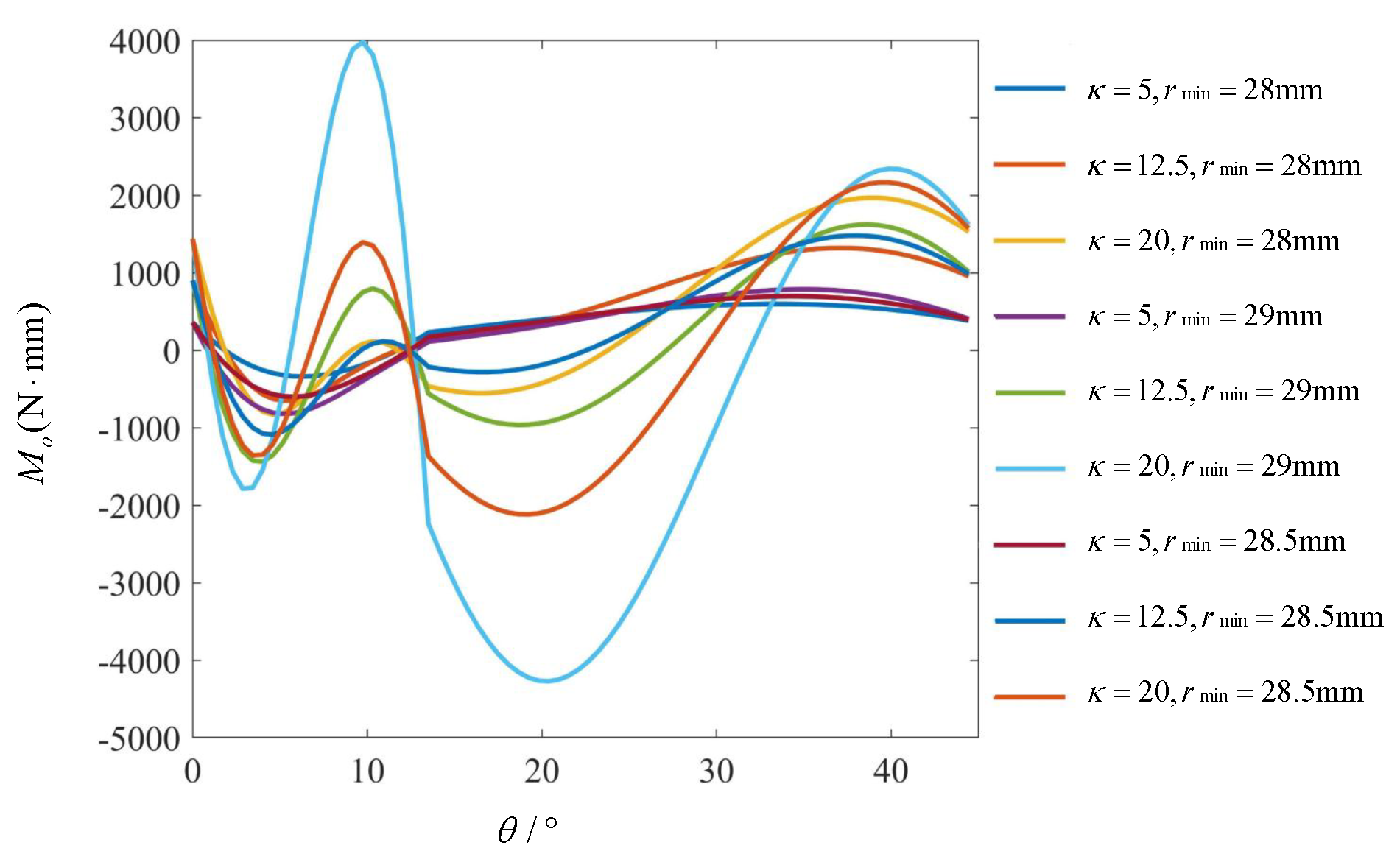
Figure 10.
The influence of and n on , where
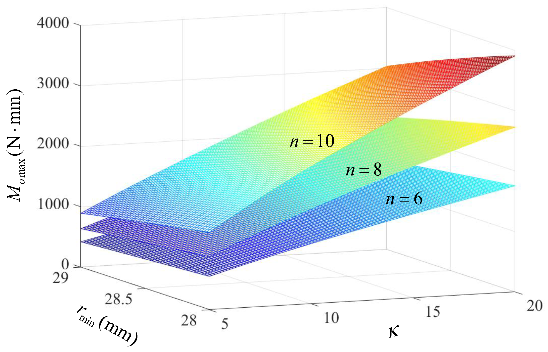
Figure 11.
Prototype of the CTSA-FA hand.
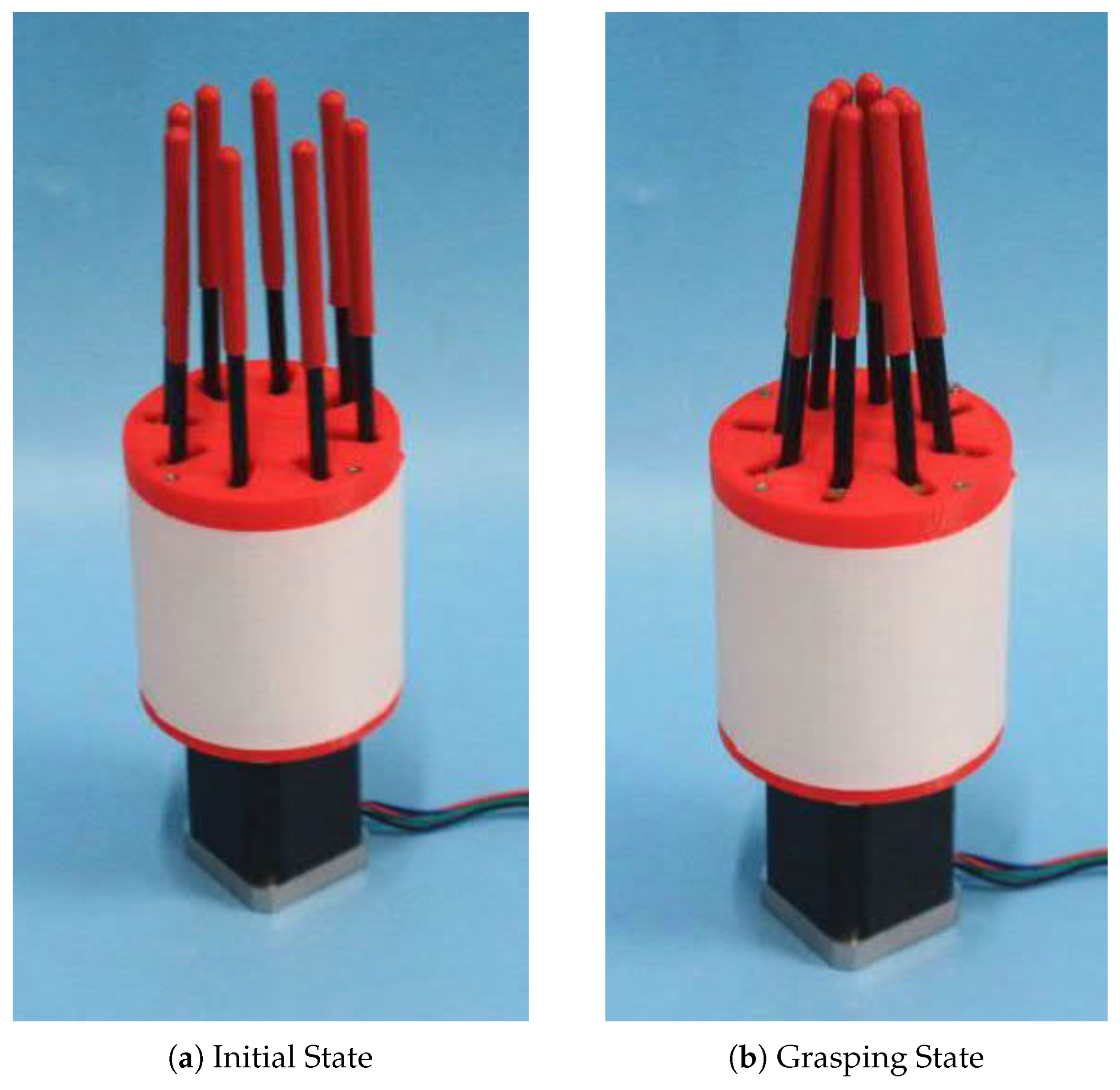
Figure 12.
Representative adaptive grasping experiments of the CTSA-FA hand.
Disclaimer/Publisher’s Note: The statements, opinions and data contained in all publications are solely those of the individual author(s) and contributor(s) and not of MDPI and/or the editor(s). MDPI and/or the editor(s) disclaim responsibility for any injury to people or property resulting from any ideas, methods, instructions or products referred to in the content. |
© 2026 by the authors. Licensee MDPI, Basel, Switzerland. This article is an open access article distributed under the terms and conditions of the Creative Commons Attribution (CC BY) license (http://creativecommons.org/licenses/by/4.0/).
Copyright: This open access article is published under a Creative Commons CC BY 4.0 license, which permit the free download, distribution, and reuse, provided that the author and preprint are cited in any reuse.


