Submitted:
03 February 2026
Posted:
03 February 2026
You are already at the latest version
Abstract
To address the issues of high latency and poor reliability caused by the reliance on wireless communication feedback in traditional capacitive power transfer (CPT) systems, this paper proposes a prediction algorithm for the output voltage and current of the receiver based on the electrical parameters of the transmitter. This algorithm can accurately estimate the output state of the receiver using only real-time measurement information from the transmitter. Based on this prediction result, an autonomous constant-voltage (CV) and constant-current (CC) control strategy without feedback from the receiver is further implemented. An experimental prototype is constructed, and constant output voltage of 25.2V and constant output current of 2A are achieved at different transfer distances, with the maximum efficiency 91.4%. This verifies the accuracy of the proposed prediction algorithm and the feasibility and effectiveness of the proposed CV and CC control strategy.
Keywords:
capacitive power transfer
; constant-voltage and constant-current
; prediction
1. Introduction
Capacitive power transfer (CPT) is a non-contact energy transmission technology based on electric field coupling. Its basic principle is to utilize a high-frequency alternating electric field to form a displacement current path between the transmitting plate and the receiving plate, thereby achieving wireless transmission of electrical energy. Specifically, when a high-frequency alternating voltage is applied to the transmitting plate, an alternating electric field is formed around it. This electric field induces a corresponding high-frequency voltage in the receiving plate through capacitance coupling, and then forms an electric current in the load circuit, thereby achieving the transfer of energy from the transmitting end to the receiving end [1,2]. Compared with the traditional inductive (magnetic coupling) power transfer technology, CPT has several prominent advantages, including a simpler structure, lower cost, lighter weight, less electromagnetic radiation interference, and less sensitivity to nearby metallic objects [3,4,5]. This is mainly because the electric field energy is mainly confined within the limited space between the coupled plates, and will not induce significant eddy current losses in the surrounding metal structures, thereby effectively avoiding the common shielding problems and energy losses in magnetic field-based wireless power transfer systems [6,7,8]. Thanks to these characteristics, CPT technology demonstrates unique advantages in application scenarios with high requirements for space, safety and anti-interference performance, such as implantable biomedical electronic devices, underwater detection and operation devices, and static or dynamic wireless charging systems for electric vehicles, etc. [9,10,11,12].
However, the CPT system still faces several key challenges on its way to practical application. To achieve efficient battery charging, the system usually needs to automatically switch between constant current and constant voltage output modes based on the battery status. However, due to the generally small equivalent coupling capacitance of the CPT coupling mechanism, large inductance value components are often introduced in the compensation network to achieve system resonance and efficient power transmission [13,14], or multi-stage composite compensation topologies such as LC-CL and LCC are adopted to enhance performance [15,16,17,18,19]. Although these designs can improve the transmission efficiency to a certain extent, they also make the system extremely sensitive to the positional offset of the coupling mechanism. Once misalignment occurs, the output performance will decline significantly. To enhance the system’s anti-offset capability, some studies have attempted to use high-order compensated topologies [20,21,22], F-type compensation networks [23], or design methods based on parity-time symmetry [24], but these solutions often encounter problems such as efficiency reduction, output instability, and increased voltage and current stress on components when there is a frequency mismatch, temperature drift of component parameters, or load changes. Furthermore, in terms of system control, to achieve efficient and reliable energy transmission and simplify the structure of the receiving end, a strategy that does not require feedback information from the receiving end and relies solely on the transmitting end for one-way control has become an ideal choice. However, traditional CPT systems mostly depend on the receiving end to sample voltage or current signals and send them back to the transmitting end controller via wireless communication. This in-band or out-of-band communication method not only introduces signal delay, increases system complexity and instability, but also faces problems of significant communication attenuation and low reliability in special environments such as underwater. Therefore, developing a transmitter autonomous control strategy that does not rely on feedback from the receiving end and has strong robustness has become one of the key issues that need to be urgently broken through for the practical application of CPT technology at present.
To address the issue of excessively high communication delay in current CPT systems, this paper proposes a prediction algorithm for the output voltage and current at the receiver based on the electrical parameters on the transmitter. This algorithm can accurately estimate the output state at the receiver by only using the real-time measurement information on the transmitter. Based on this prediction result, this paper further deduces and implements an autonomous constant-voltage (CV) and constant-current (CC) control strategy that does not require feedback from the receiver. Finally, experiments are conducted to verify the accuracy of the proposed prediction algorithm and the feasibility and effectiveness of this control strategy in practical operation.
2. System Structure and Model
2.1. System Structure Based on Unilateral Control
Figure 1a shows the circuit topology of the proposed unilateral control CPT system. The transmitter consists of an inverter and a compensation network. The receiver consists of a compensation network and a rectifier circuit. The transmitter and receiver are connected by a coupler, which consists of plates P1-P4.
The inverter and rectifier are equivalent to a negative resistance -RN and a load resistance Re, respectively. The negative resistance supplies power to the system, while load resistance consumes power from the system. The coupled capacitance CM reflects the degree of coupling between the transmitter and receiver. Figure 1b shows the equivalent circuit topology of the proposed CPT system. The transmitter consists of resonant capacitance C1, resonant inductance L1, internal resistance R1, and negative resistance -RN. The receiver consists of resonant capacitance C2, resonant inductance L2, internal resistance R2, and load resistance Re. The high-quality factors of the system enable the application of fundamental wave analysis to analyze the system. Then, u1, u2, i1, and i2 can be represented by the phasors , , , and .
2.2. Mathematical Model and Characteristic Analysis
According to the equivalent circuit topology and Kirchhoff’s Voltage Law (KVL), the steady-state circuit model of the system can be written as
where Δ=C1C2+CmC1+CmC2. The transmitter’s natural resonant angular frequency is denoted as ωT=1/(L1C1)1/2. The receiver’s natural resonant angular frequency is ωR=1/(L2C2)1/2. To enhance system efficiency, the resonant angular frequencies of the transmitter and receiver satisfy ωT=ωR=ω0. Typically, L1=L2 and C1=C2 are used to simplify the design of system parameters. The transmitter’s quality factor is QT=ω0LT/(-RN+R1). The receiver’s quality factor is QR=ω0LR/(Re+R2). (1) can be rewritten as
where k=Cm/(C1C2)1/2 is the coupling coefficient. According to (2), the characteristic equation of the system can be derived as
The real and imaginary parts of the characteristic equation can be separated as
According to the imaginary equation of (4), we have
According to (6), combining the real equation of (4) with (5), the system angular frequency solution can be obtained as
where critical coupling coefficient kC is
Figure 2 shows the system angular frequency characteristics. When kC<k≤1, the system exhibits angular frequency bifurcation. When 0<k≤kC, the system operates at a single angular frequency.
3. System Control Strategy
3.1. Output Voltage and Current Prediction Algorithm
The measured values of output voltage and current provide a reference benchmark for the system’s constant output control. The typical approach is the receiver samples the output signal, then transmits the signal to the transmitter via communication, thereby controlling the system output. However, this method suffers from high signal delay and complex system design, which increases the complexity of system control. Therefore, an output voltage and current prediction algorithm based on transmitter’s parameters is proposed here to address the aforementioned challenges.
According to (1), the circuit equation can be rewritten as
where the transmitter impedance Z1 and receiver impedance Z2 are respectively
The receiver current and equivalent load resistance Re can be derived according to (9), as follows
Combined (11) with (12), eliminated receiver current . The equivalent load resistance Re can be rewritten as
where the real part Re[Re] and imaginary part Im[Re] of the equivalent load resistance Re are as follows
The resonant inductance and resonant capacitance of the transmitter and receiver are related by L1=L2=L and C1=C2=C.
Since the equivalent load resistance Re is a positive real number, the imaginary part Im[Re] is set to zero, and we obtain
According to (15), the following relationship exists between coupling capacitance Cm and system component parameters:
By combining the real part Re[Re] of (14) with (16), the analytical equation for the system predicting equivalent load resistance is
The coupling capacitance Cm and equivalent load resistance Re require analytical expressions to be selected based on the operating angular frequency of the system as defined in (7). When the system operating angular frequency satisfies ω2,3, (16) and (17) should both be selected as kC<k≤1. When the system operating angular frequency satisfies ω1, (16) and (17) should both be selected as 0<k≤kC.
According to (1), (16), (17), and Ohm’s Law, the expression for predicting the output current and voltage is:
In practical applications, the receiver load requires rectification. The system parameters before and after rectification exhibit the following relationship:
Since the prediction algorithm derivation process is relatively complex, the system’s prediction flowchart is shown in Figure 3 to enhance readability. To validate the feasibility of the proposed algorithm, we constructed a corresponding system based on Simulink software for simulation verification of the proposed algorithm. Figure 4 shows the simulation verification of the proposed algorithm. The simulation results reveal that the proposed algorithm can predict the system’s output voltage and current with high accuracy.
3.2. CV and CC Control Strategy
Based on the above prediction algorithm, this paper proposes unilateral control strategy for CV and CC control, as illustrated in Figure 5. By capturing the transmitter current frequency and comparing it with the operating frequency under negative resistance control in (7), the system operating state can be determined. By capturing the transmitter current and voltage amplitude, the receiver output current and voltage can be predicted using (16), (17), and (18).
The primary AC voltage and the input DC voltage are related by an equation. Based on the Fourier decomposition of the primary AC voltage, the relationship between and is as follows:
where DS represents the PWM duty cycle of the inverter.
The PI controller is employed to control DS, utilizing the prediction signal as feedback input and the target voltage or current as the PI control reference. Based on this control, the output current and voltage of the receiver can be maintained constant at a set value.
4. Experimental Validation
4.1. Experimental Setup
The experimental prototype is depicted in Figure 6. The rectifier section employs four IRF540NPBF P-channel MOSFETs to form a full-bridge inverter configuration, while the full-bridge rectifier structure consists of four SSL56C Schottky barrier diodes. The coupling structure consists of two pairs of 10x10mm capacitor plates filled with freshwater medium. The coupling capacitance value can be adjusted by altering the distance d between the plates. The circuit parameters are presented in Table 1.
The input DC voltage for this experiment was set to 36V, with the system operating frequency range of 260-300kHz. Since practical wireless charging applications primarily involve charging battery loads, which are divided into two stages: constant-voltage (CV) charging and constant-current (CC) charging [25].
This paper employs a DC electronic load to simulate the CC and CV charging process of six-cell lithium batteries connected in series. The experimental design specifies a CC charging of 2A and a CV charging of 25.2V. According to [26], the equivalent series resistance (ESR) ranges from 9 to 12.6Ω during the CC. The ESR ranges from 12.6 to 126Ω during the CV. Therefore, the load design for CC prediction experiments is 9 to 13Ω, while the load design for CV prediction experiments is 20 to 100Ω. The experiment was designed with three transfer distances: d=15mm, d=20mm, and d=25mm to validate the accuracy and feasibility of the prediction algorithm and control strategy at different transfer distances.
4.2. Experimental Results of Proposed Algorithm
To validate the accuracy of the proposed parameter prediction algorithm, prediction experiments were conducted under different distances and loads. Figure 7 shows the predicted voltage and current values alongside the experimental values.
As shown in Figure 7, the predicted current and voltage exhibit minimal deviation from the experimental values. At all three distances, the maximum relative error for current prediction is 7.87%, while the maximum relative error for voltage prediction is 8.46%. The experimental prediction error falls within a reasonable range. The primary error in the current prediction experiment stems from the on-resistance of MOSFETs in the inverter and switching losses, which cannot be ignored at relatively high current levels. This discrepancy between the inverter waveform and the theoretical model leads to errors in uin. The primary error in the voltage prediction experiment stems from the relatively low output current under high load conditions. This causes the rectifier diodes on the receiver to conduct for longer durations, resulting in rectification waveforms that deviate from the theoretical model. Ultimately, this leads to errors in Uo and Io. Additionally, the sampling accuracy of the transmitter is also a significant factor contributing to prediction errors. Consequently, the proposed prediction algorithm is both feasible and accurate.
4.3. Experimental Results of Proposed Strategy
To validate the feasibility of the proposed control strategy, this paper employed the strategy to conduct constant-voltage and constant-current output experiments under different distances and loads. The experiments maintained a CV output of 25.2V and a CC output of 2A. Figure 8 shows the control current and voltage values for this experiment. Figure 9 shows the transfer efficiency of the experimental system. Figure 10 shows the current and voltage waveforms at the input and output terminals of the experimental system.
Figure 8 is the CC and CV curves at three transfer distances under load variation. The curve in Figure 8 demonstrates that the charging current and voltage of the simulated battery load exhibit high stability under this control strategy. The experimental results indicate a minimal deviation between the output current and voltage with the controlled target values. The maximum relative error for CC charging at three distances is 7.55%, and the maximum relative error for CV charging is 7.21%, which demonstrates the feasibility of this control strategy.
Figure 9 records the transfer efficiency throughout the experiment. As shown in Figure 9, the efficiency during the CC charging stage increases with increasing load, while efficiency decreases as load increases under CV control. The transfer efficiency of the system exceeds 85% at all three distances, and the maximum efficiency is 91.4%.
Figure 10 shows the experimental waveforms for different loads at d=25mm. It can be observed that the phase between uin and -i1 is 0° under different loads.
5. Conclusions
This paper addresses the inherent high communication latency issue in traditional CPT control methods by proposing an output voltage-current prediction algorithm based on transmitter parameters. This algorithm eliminates the communication requirements of traditional CPT control, thereby resolving the high latency caused by communication. Furthermore, a CV/CC control strategy based on this algorithm is introduced, providing a reliable solution for the CV-CC applications of CPT. Finally, experiments validate the accuracy of the proposed prediction algorithm and the feasibility of the control strategy.
Author Contributions
Conceptualization, Z.H.; methodology, Z.H.; validation, Z.H.; writing—original draft preparation, Z.H.; writing—review and editing, Z.H and Y. L.; supervision, Y. L.; project administration, Y. L.; All authors have read and agreed to the published version of the manuscript.
Funding
This research received no external funding.
Data Availability Statement
Data are contained within this article.
Conflicts of Interest
The authors declare no conflicts of interest.
References
- Huang. Z., Wang. Y., Wang. J., and L. X. Detuned Design Methodology of Anti-Misalignment Capacitive Power Transfer Converter. IEEE J. Emerg. Sel. Top. Power Electron. 2025, 13, 5435-5446. [CrossRef]
- Estevez-Encarnacion, E.S.; Hernandez-Gonzalez, L.; Ramirez-Hernandez, J.; Juarez-Sandoval, O.U.; Guevara-Lopez, P.; Avalos Arzate, G. Design of Stabilizing Network for Capacitive Power Transfer Transmitter Operating at Maximum Power Transfer Limiting the Voltage Gain in Resonant Capacitors. Electronics 2024, 13, 3859. [CrossRef]
- Liu. X., Cai. C., Wu. S., Li. C., Cui. Q., and Ren. X. Modeling and Analysis of Undersea Capacitive Power Transfer Based on Conduction Current in Seawater. IEEE Trans. Power Electron. 2025, 40, 4640 - 4651. [CrossRef]
- Zhang, X.; Lian, J. A Novel Coupler of Capacitive Power Transfer for Enhancing Underwater Power Transfer Characteristics. Electronics 2024, 13, 74. [CrossRef]
- Zhang, J.; Yao, S.; Pan, L.; Liu, Y.; Zhu, C. A Review of Capacitive Power Transfer Technology for Electric Vehicle Applications. Electronics 2023, 12, 3534. [CrossRef]
- Farghly. A., Mohamed. A., Awad. H., Abdelfatah, S., Alharbi. M., and Alqarni. M. A Comprehensive Review of Wireless Power Transfer Techniques for Electric Vehicle Charging. IEEE Access 2025, 13, 199683 - 19971. [CrossRef]
- Da. C., Li. F., Nie. M., Li. S., Tao. C., and Wang. L. Undersea Capacitive Coupled Simultaneous Wireless Power and Data Transfer for Multiload Applications. IEEE Trans. Power Electron. 2025, 40, 2630 - 2642.
- Yu. Z., Xiao W., Zhang B., and Qiu D. Development Status of Electric-Field Coupled Wireless Power Transmission Technology. Transactions of China Electrotechnical Society,2022,37. 1051-1068.
- S. Nag, A. Koruprolu, S. M. Saikh, R. Erfani and P. Mohseni. Auto-Resonant Tuning for Capacitive Power and Data Telemetry Using Flexible Patches. IEEE Trans. Circuits Syst. II Express Briefs 2020, 67,1804-1808. [CrossRef]
- L. Yang et al. Comparison Survey of Effects of Hull on AUVs for Underwater Capacitive Wireless Power Transfer System and Underwater Inductive Wireless Power Transfer System. IEEE Access 2022, 10, 125401-125410. [CrossRef]
- Shu, X.; Ou, R.; Wu, G.; Yang, J.; Jiang, Y. Extended-Distance Capacitive Wireless Power Transfer System Based on Generalized Parity–Time Symmetry. Electronics 2024, 13, 4731. [CrossRef]
- L. Yang, M. Ju and B. Zhang. Bidirectional Undersea Capacitive Wireless Power Transfer System. IEEE Access 2019, 7, 121046-121054. [CrossRef]
- M. P. Theodoridis. Effective Capacitive Power Transfer. IEEE Trans. Power Electron. 2012, 27, 4906-4913. [CrossRef]
- Y. Jiang, Y. Zhou, B. Zhang, W. Chen, Q. Chen and X. Shu. A Robust Capacitive Power Transfer System via Fractional-Order Autonomous Circuit. IEEE J. Emerg. Sel. Top. Power Electron. 2024, 12, 3258-3267. [CrossRef]
- Y. Wu, Q. Chen, X. Ren and Z. Zhang. Efficiency Optimization Based Parameter Design Method for the Capacitive Power Transfer System. IEEE Trans. Power Electron. 2021, 36, 8774-8785. [CrossRef]
- X. -D. Qing, Z. -H. Wang, Y. -G. Su, Y. -M. Zhao and X. -Y. Wu. Parameter Design Method With Constant Output Voltage Characteristic for Bilateral LC-Compensated CPT System. IEEE J. Emerg. Sel. Top. Power Electron 2020, 8, 2707-2715. [CrossRef]
- Y. Wang, H. Zhang and F. Lu. Capacitive Power Transfer With Series-Parallel Compensation for Step-Up Voltage Output. IEEE Trans. Ind Electron. 2022, 69, 5604-5614. [CrossRef]
- H. Zhang, F. Lu, H. Hofmann, W. Liu and C. C. Mi. An LC-Compensated Electric Field Repeater for Long-Distance Capacitive Power Transfer. IEEE Transactions on Industry Applications 2017, 53, 4914-4922. [CrossRef]
- Chen. T., Cheng. C., Zhang. X., Li. G., Guo. Y., Mi. C. A Double-Sided LCL-Compensated Network for the Strongly Coupled CPT System With Minimum Plate Voltage Stresses. IEEE J. Emerg. Sel. Top. Power Electron 2024, 12, 4275 - 4287. [CrossRef]
- F. Lu, H. Zhang, H. Hofmann and C. C. Mi. A Double-Sided LC-Compensation Circuit for Loosely Coupled Capacitive Power Transfer. IEEE Trans. Power Electron. 2018, 33, 1633-1643. [CrossRef]
- Liu. W., Luo. B., He. X., Wang. Z., and Mai. R. Analysis of Compensation Topology with Constant-Voltage/Current Output for Multiple Loads Capacitive Power Transfer System. CSEE Journal of Power and Energy Systems. 2025, 11, 802-814.
- A Novel Compensation Circuit of the Capacitive Power Transfer System With High Performance of Anti-Misalignment. IEEE Access 2024, 12, 83774 - 83781. [CrossRef]
- Y. -G. Su, Y. -M. Zhao, A. P. Hu, Z. -H. Wang, C. -S. Tang and Y. Sun. An F-Type Compensated Capacitive Power Transfer System Allowing for Sudden Change of Pickup. IEEE J. Emerg. Sel. Top. Power Electron 2019, 7, 1084-1093. [CrossRef]
- W. Gu, D. Qiu, X. Shu, B. Zhang, W. Xiao and Y. Chen. A Constant Output Capacitive Wireless Power Transfer System Based on Parity-Time Symmetric. IEEE Trans. Circuits Syst. II Express Briefs 2023, 70, 2585-2589. [CrossRef]
- Y. Li et al. Reconfigurable Intermediate Resonant Circuit Based WPT System With Load-Independent Constant Output Current and Voltage for Charging Battery. IEEE Trans. Power Electron. 2019, 34, 1988-1992. [CrossRef]
- Y. Wang, H. Liu, H. Yu, P. Wheeler, Q. Zhou and S. Zhao. A Hybrid Battery Wireless Charger for Self-Adapting Battery Charging Curve and Anti-Misalignment. IEEE J. Emerg. Sel. Top. Ind. Electron 2023, 4, 1192-1203. [CrossRef]
Figure 1.
System circuit topology. (a) Circuit topology. (b) Equivalent circuit topology.
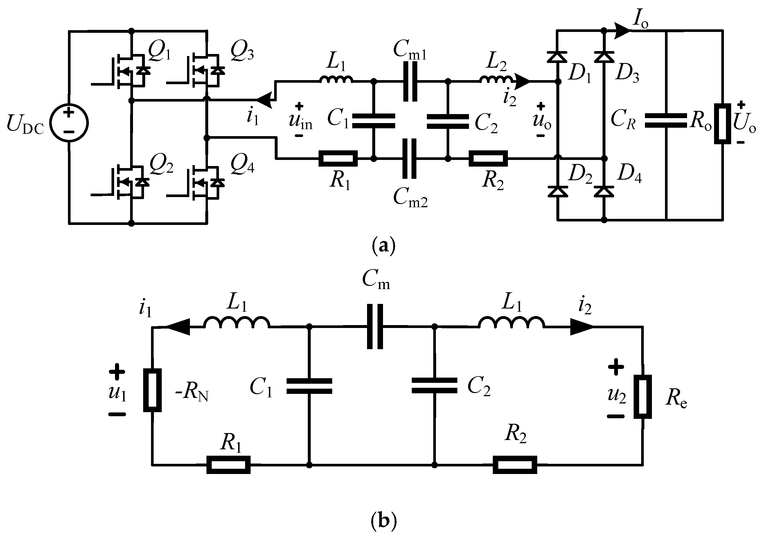
Figure 2.
Angular frequency characteristics.

Figure 3.
Prediction Flowchart.
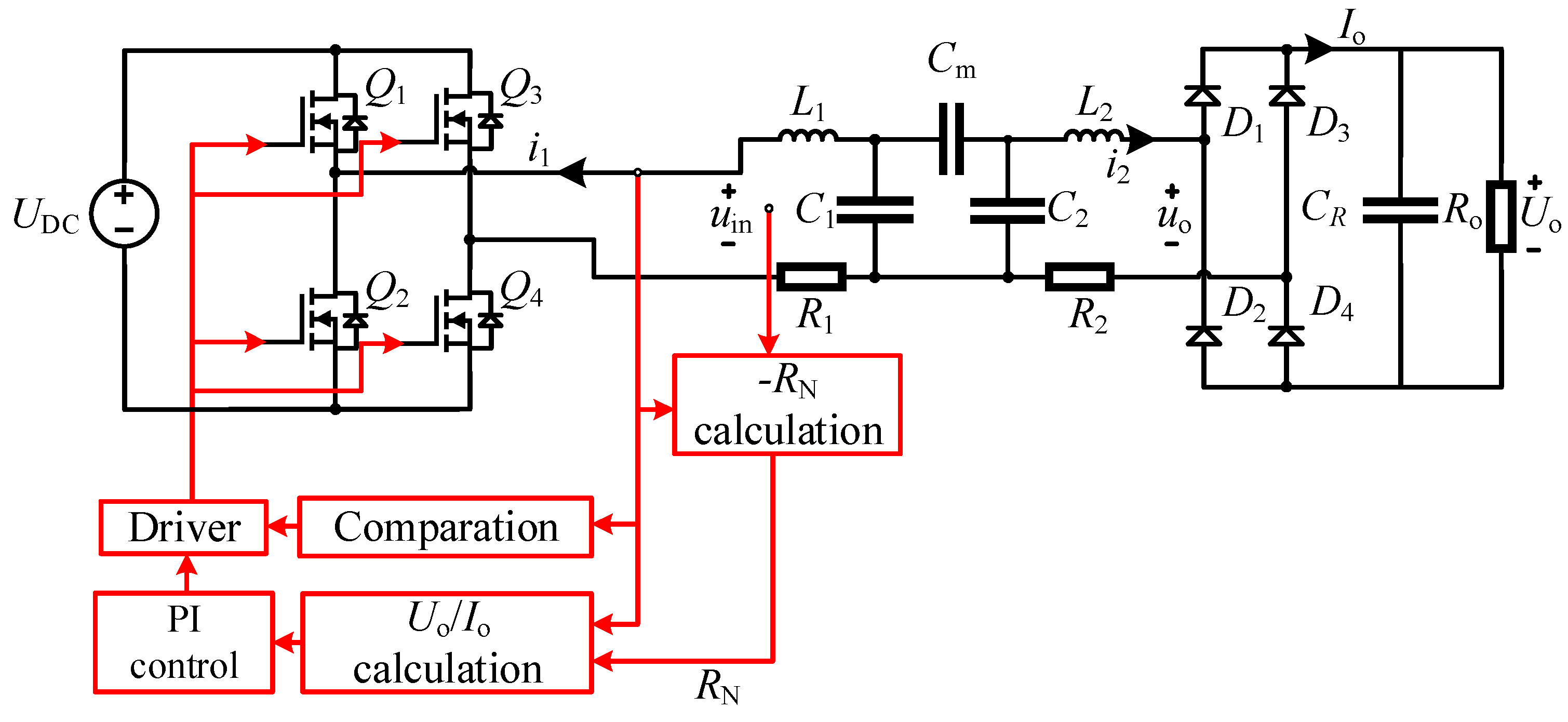
Figure 4.
Simulation Verification. (a) Current Prediction. (b) Voltage Prediction.
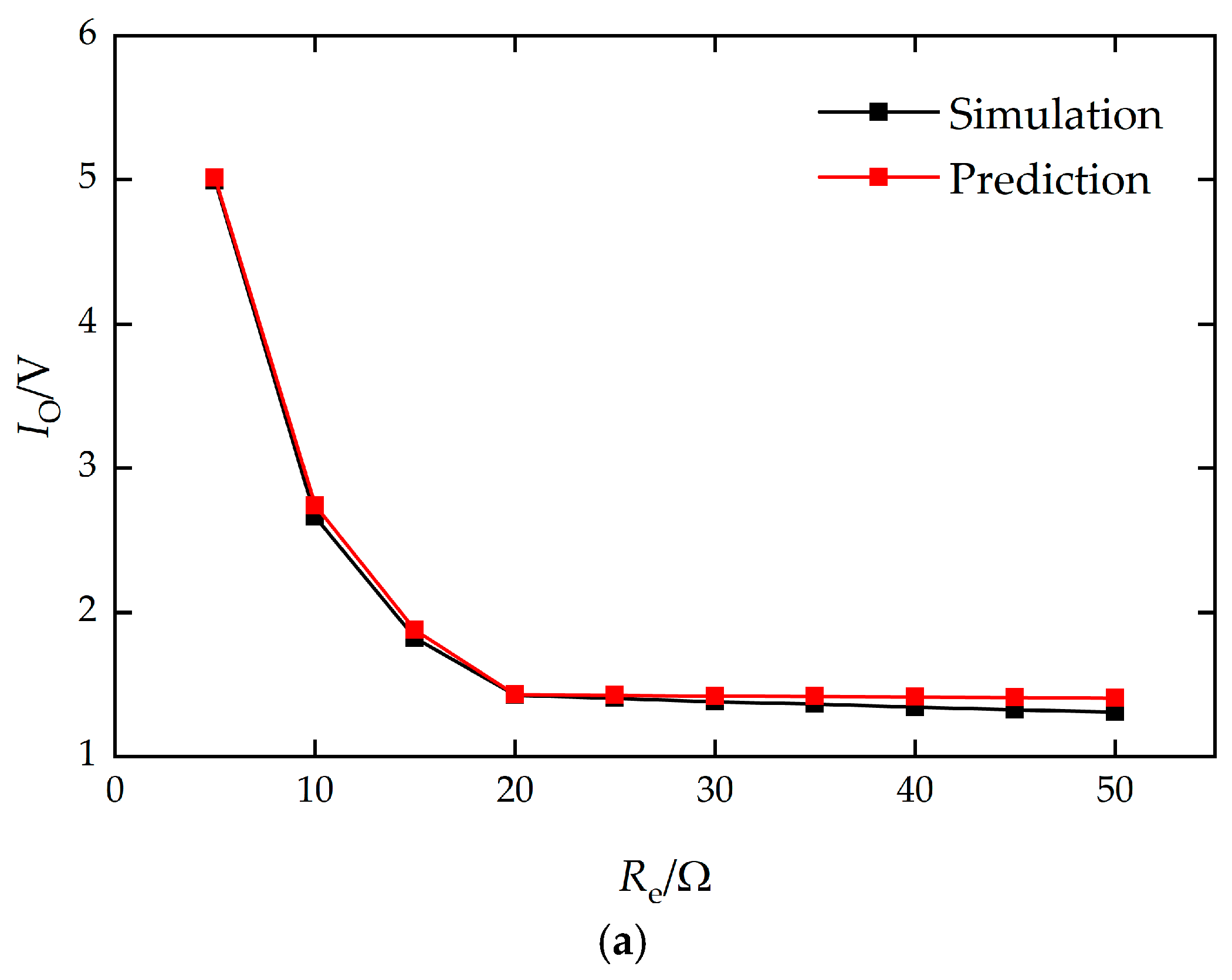
Figure 5.
Control Strategy Flowchart.
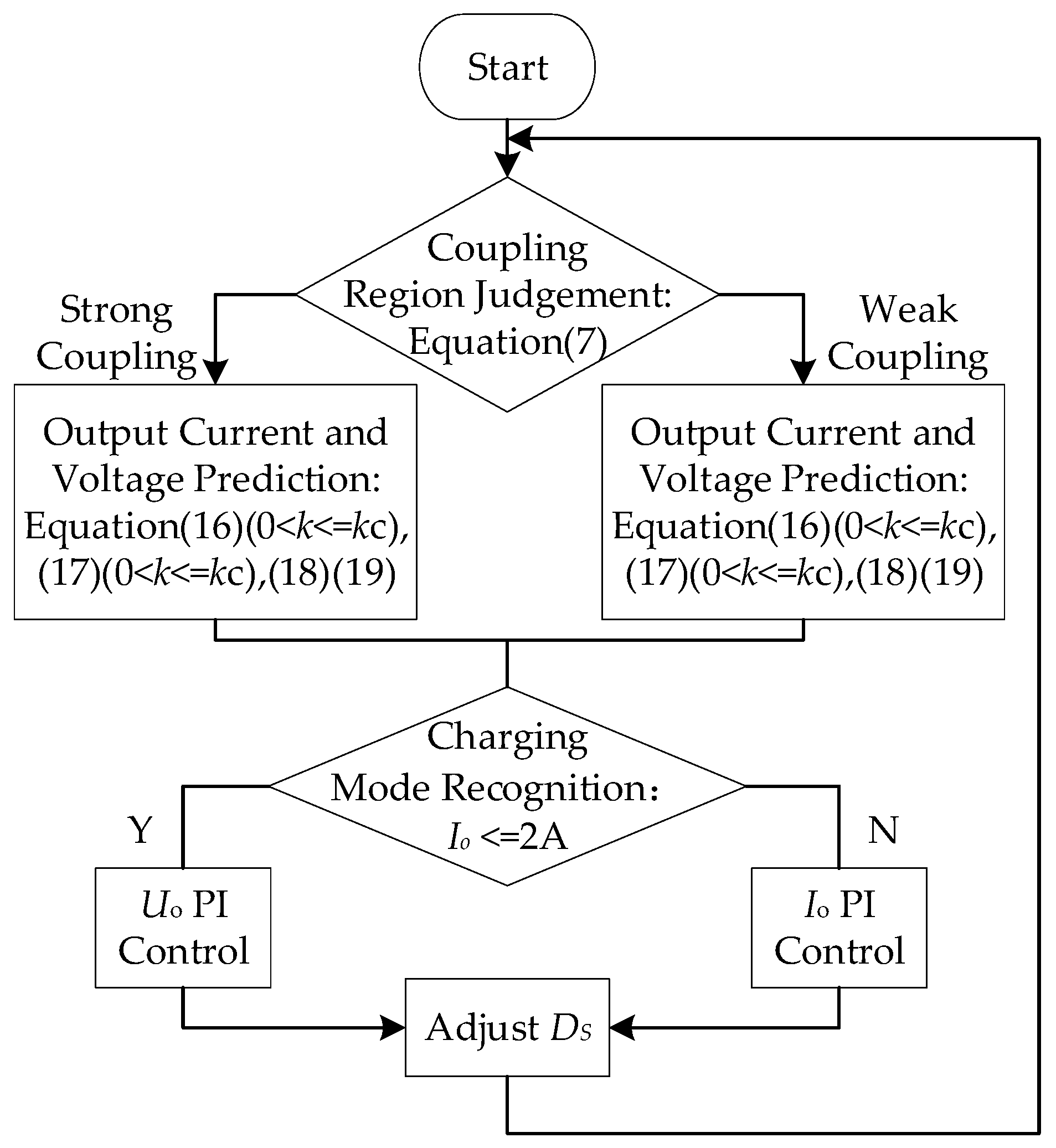
Figure 6.
Experimental prototype.
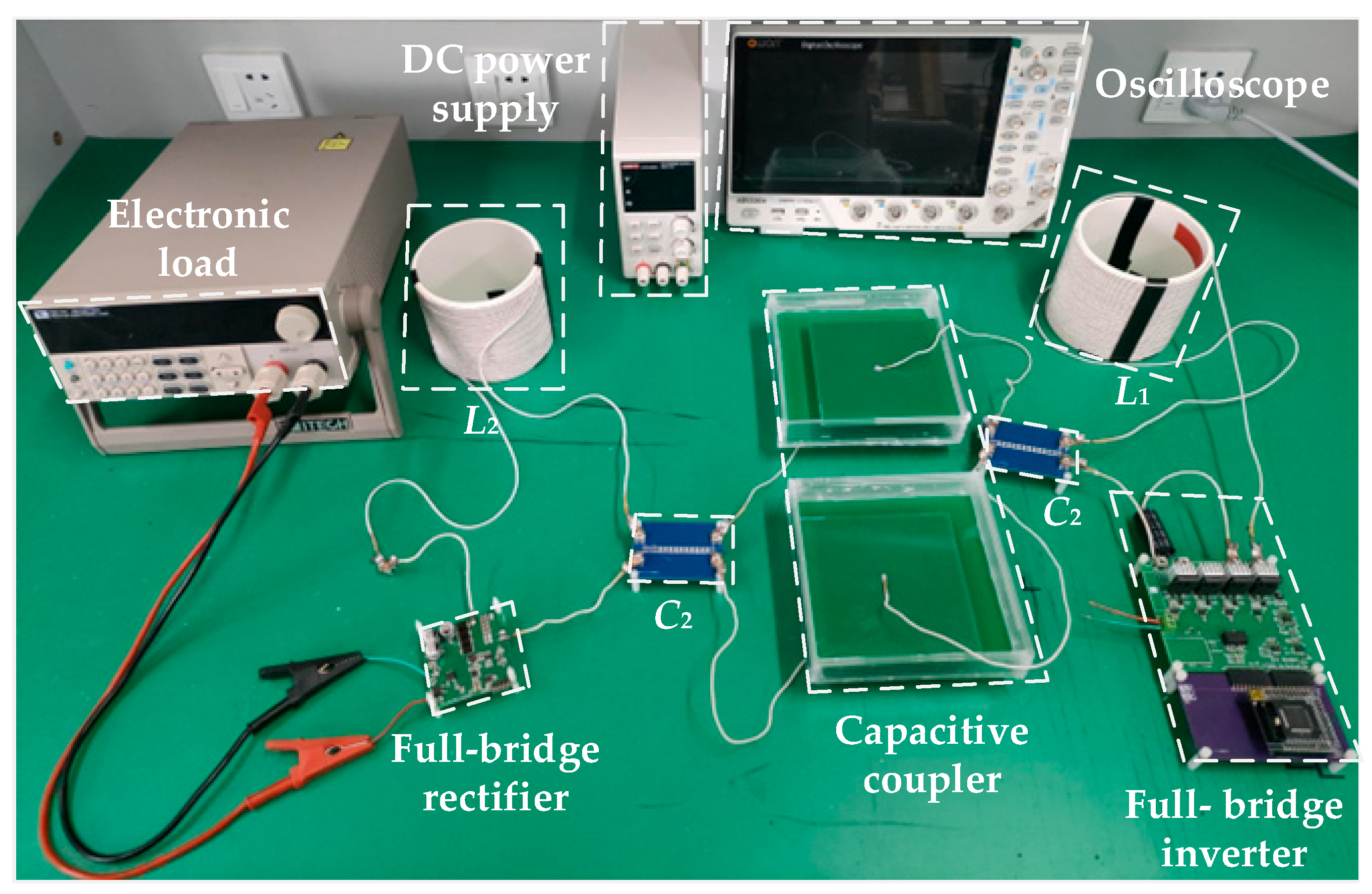
Figure 7.
The output current and voltage of the prediction experiment. (a) Output current. (b) Output voltage.
Figure 7.
The output current and voltage of the prediction experiment. (a) Output current. (b) Output voltage.
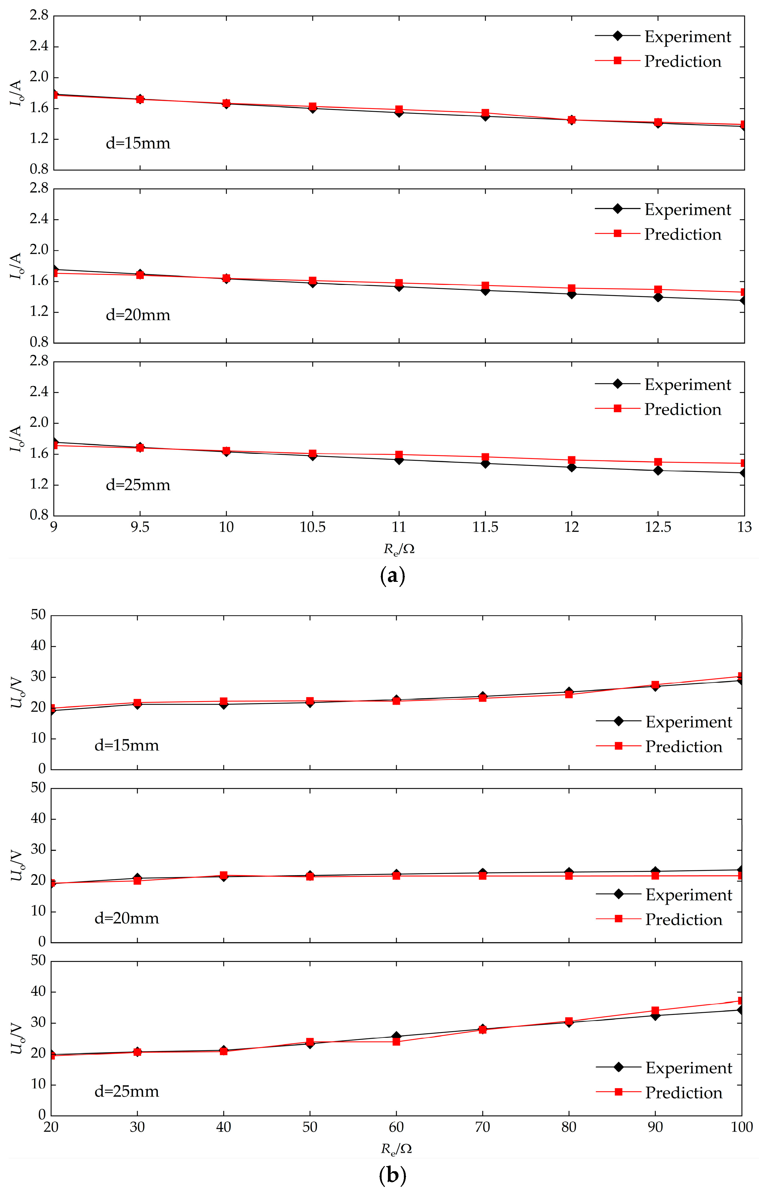
Figure 8.
The output current and voltage of the controlled experiment. (a) d=15mm. (b) d=20mm. (c) d=25mm.
Figure 8.
The output current and voltage of the controlled experiment. (a) d=15mm. (b) d=20mm. (c) d=25mm.
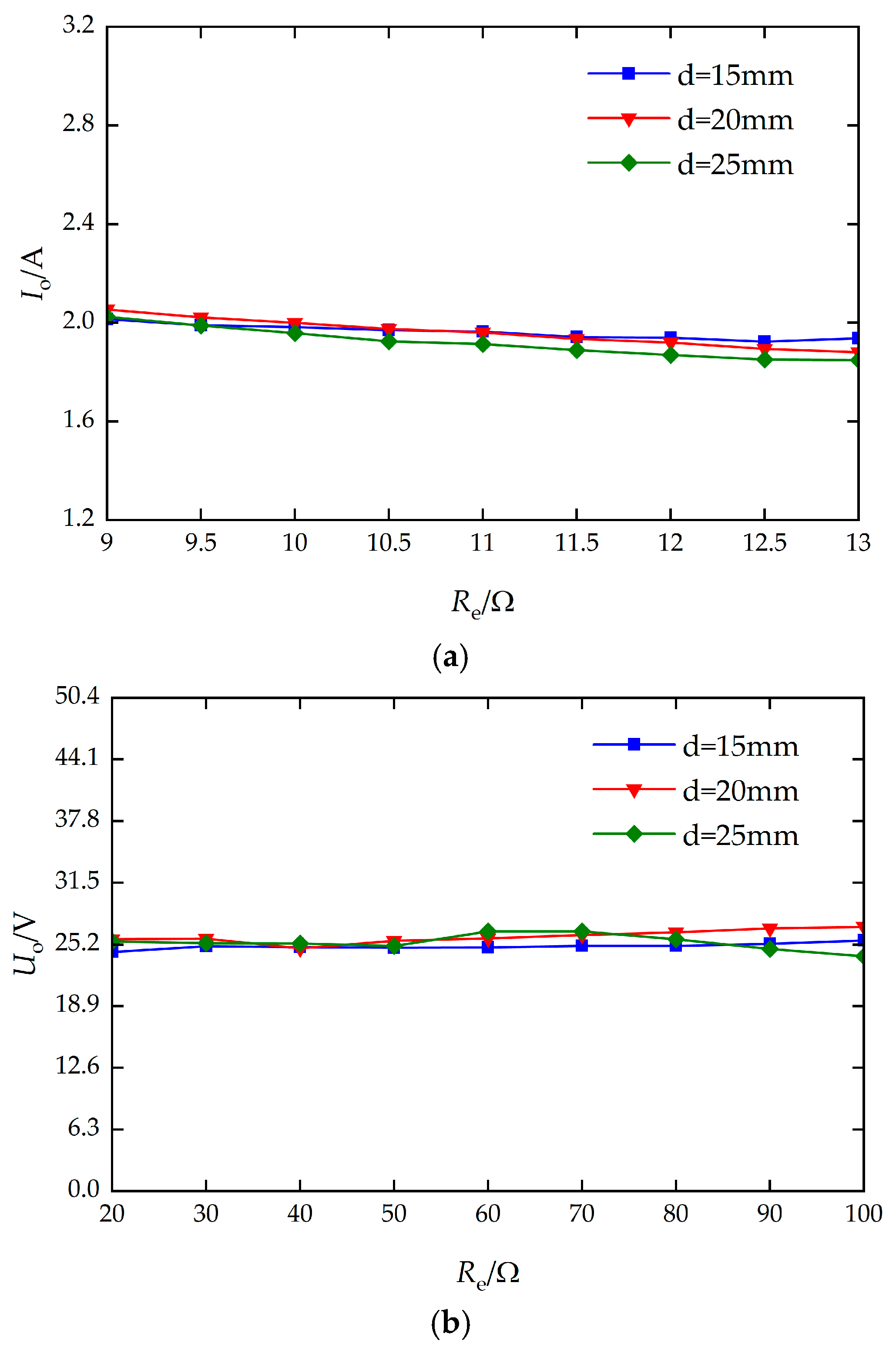
Figure 9.
The system transfer efficiency. (a) Efficiency under CC control. (b) Efficiency under CV control.
Figure 9.
The system transfer efficiency. (a) Efficiency under CC control. (b) Efficiency under CV control.
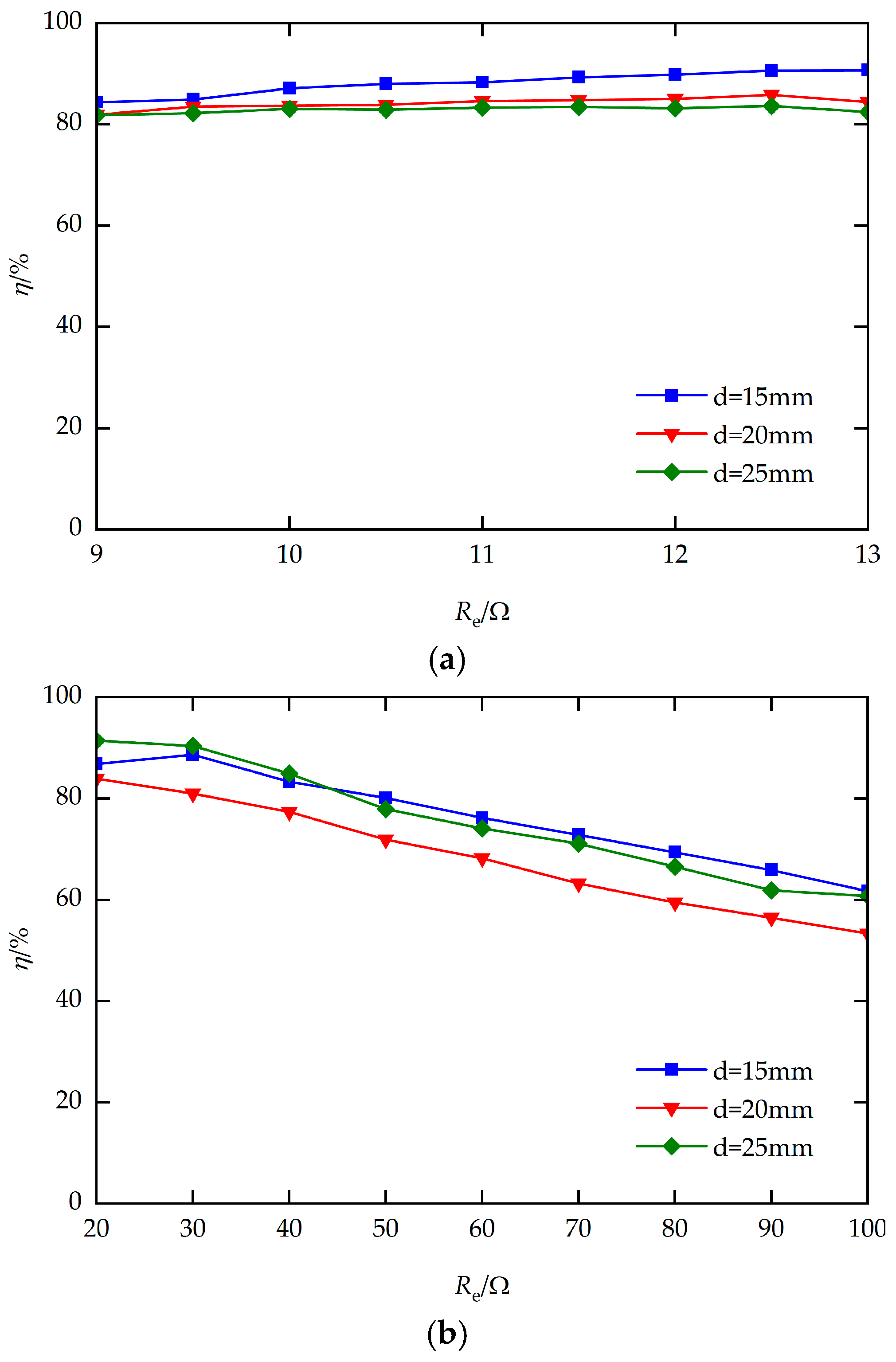
Figure 10.
Experimental waveforms. (a) Ro=9Ω. (b) Ro=13Ω. (c) Ro=30Ω. (d) Ro=70Ω.
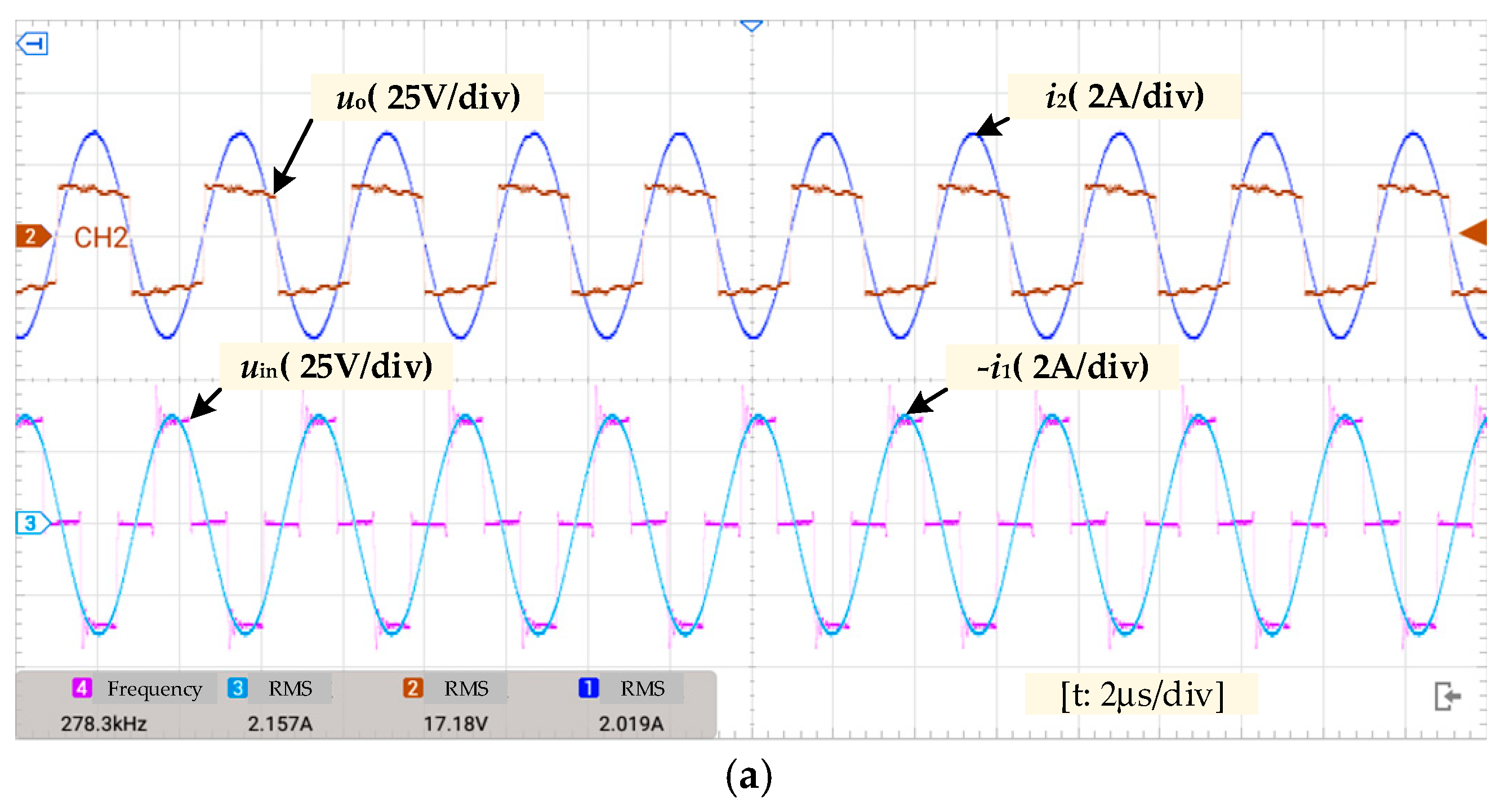

Table 1.
Parameters of the experimental prototype.
| Symbol | Values |
| L1 | 146.10μF |
| L2 | 146.10μF |
| C1 | 2.19nF |
| C2 | 2.19nF |
| R1 | 0.21Ω |
| R2 | 0.21Ω |
| CR | 660μF |
| UDC | 36V |
Disclaimer/Publisher’s Note: The statements, opinions and data contained in all publications are solely those of the individual author(s) and contributor(s) and not of MDPI and/or the editor(s). MDPI and/or the editor(s) disclaim responsibility for any injury to people or property resulting from any ideas, methods, instructions or products referred to in the content. |
© 2026 by the authors. Licensee MDPI, Basel, Switzerland. This article is an open access article distributed under the terms and conditions of the Creative Commons Attribution (CC BY) license (http://creativecommons.org/licenses/by/4.0/).
Copyright: This open access article is published under a Creative Commons CC BY 4.0 license, which permit the free download, distribution, and reuse, provided that the author and preprint are cited in any reuse.


