
Submitted:
31 January 2026
Posted:
03 February 2026
You are already at the latest version
Abstract
This study investigates the fatigue behavior of cold-finished mild steel coated with nickel as a hydrogen permeation barrier. Hydrogen was introduced to the coated specimens through electrochemical charging at controlled charging current densities to induce varying levels of hydrogen exposure. Subsequent fatigue tests were carried out to assess the impact of hydrogen permeation on fatigue life. The primary objective was to assess the influence of hydrogen on the number of cycles to failure, and to evaluate the effectiveness of nickel coatings as permeation barriers to impede hydrogen ingress under cyclic loading conditions. The experimental results revealed a non-monotonic relationship between fatigue life and hydrogen charging severity. At low to moderate hydrogen charging levels, the fatigue response of the coated steel was relatively stable, reflecting the ability of the nickel coating to limit hydrogen ingress. However, at higher charging current densities, the fatigue life decreased abruptly, indicating the existence of a threshold beyond which the protective capability of the nickel coating diminishes and hydrogen embrittlement (HE) becomes dominant. The findings from this research provide insights into the fatigue performance of nickel-coated steels and supports the informed design of structural components for service in hydrogen-rich environments.
Keywords:
hydrogen embrittlement
; diffusible hydrogen
; nickel electroplating
; cathodic charging
; cyclic loading
1. Introduction
Since the advent of industrialization, fossil fuels (coal, oil, and natural gas) have been the dominant sources of energy. From power and heat generation to transportation and manufacturing, these resources have fueled industrial growth for many years. Exorbitant dependence on these carbon-based energy sources, however, raises major concerns on their ecological impact with issues ranging from climate change, environmental degradation, and the gradual depletion of its reserves. The combustion of these fuels contributes considerably to carbon dioxide (CO2) emissions which pollute the surroundings and drives global warming. Recognizing the need to mitigate the challenges associated with the consumption of fossil fuels, several countries have resorted to exploring cleaner and sustainable alternatives that are less detrimental. Among the viable options considered for clean energy substitutes, hydrogen is identified as a promising energy carrier. Hydrogen’s attraction lies in its flexibility; it is universally abundant such that it can be produced from renewable processes like electrolysis [1], it packs a high energy content [2], and its combustion yields water rather than CO2 [3] which is much cleaner than conventional fossil fuels. Canada, the United States and several European and Asian countries have begun integrating hydrogen energy into their national energy development initiatives. In parallel, decarbonization strategies such as hydrogen-blending with natural gas are being implemented to reduce global greenhouse gas emissions. Despite this progress, the complete deployment of hydrogen into modern energy applications has its challenges. Unlike hydrocarbons, hydrogen is an extremely small and highly diffusive atom that interacts with the microstructure of materials in ways that can measurably degrade their mechanical properties. The very infrastructure needed to realize the transition to a hydrogen economy – pipelines, storage tanks, vessels, etc. – is therefore at risk of compromised structural integrity, with hydrogen embrittlement being the most critical problem.
Hydrogen embrittlement (HE) is one of the most insidious forms of material degradation that plagues structural metals. HE occurs when atomic hydrogen permeates into a metal and degrades its mechanical properties, often resulting in a reduction in ductility and fracture toughness [4]. The interaction between hydrogen and the metal microstructure has been studied extensively over the years and has resulted in the proposal of various models that seek to describe the phenomena of HE considering that no single theory completely explains the effects of hydrogen on metals. Often, these mechanisms occur simultaneously and they include hydrogen-enhanced decohesion mechanism (HEDE) [5,6], hydrogen-enhanced localized plasticity (HELP) [7,8], adsorption-induced dislocation emission (AIDE) [9], hydrogen pressure theory (HPT) [10], hydrogen-enhanced strain-induced vacancy (HESIV) [11], hydrogen induced phase transformation (HIPT) [12,13], and hydrogen assisted micro-void coalescence [14,15]. Industrially, HE remains a recurring challenge across multiples sectors where infrastructures are exposed to hydrogen-rich environments for prolonged periods. Ferritic steels are particularly prone to HE due to their body-centered cubic (BCC) crystal structure, characterized by high hydrogen diffusivity and low solubility, which facilitates rapid transport of hydrogen [16]. Owing to its latent nature, HE damage can accumulate without obvious signs, and the consequences are usually severe. The incursion of atomic hydrogen can destabilize metals by reducing the bonding strength between metal atoms, augmenting dislocation behavior which alters how metals plastically deform, and even recombining into molecular hydrogen within the metal to create internal pressures that can facilitate the initiation and propagation of cracks [17]. For various engineering practices, these effects are very concerning especially when structural components operate under varying stresses in hydrogenated mediums which are ideal conditions for both hydrogen-assisted damage and fatigue failure.
Fatigue failure occurs when a material is subjected to repeated cyclic stresses below its ultimate tensile strength, leading to progressive weakening and eventual fracture of the material. This mode of failure typically initiates at stress concentrators such as surface defects, notches, and inhomogeneous microstructural features where microscopic cracks form and extend incrementally with each loading cycle [18]. The rate at which these cracks propagate depends on the magnitude and nature of the applied stress [19], and also the material’s intrinsic properties [20,21], including microstructure, hardness, and fracture toughness, amongst other factors. As these cracks grow, they subsequently reach a critical size where the cross-sectional area of the material is unable to sustain the applied load which culminates in sudden fracture often with no prior warnings. Generally, fatigue failure can be classified based on the number of loading cycles to fracture. Failures occurring around 104 cycles or fewer are deemed as low-cycle fatigue and typically involve elastoplastic deformation, whereas high-cycle fatigue occurs beyond approximately 106 cycles and is predominantly governed by elastic deformation [22,23]. Hydrogen embrittlement and fatigue failure are two interrelated phenomena that significantly influence the structural integrity and service life of metallic components. The synergy between these otherwise distinct mechanisms is immensely relevant in applications where pressurized fluids are stored or transported, such as pipelines. Such systems endure cyclic loading due to fluctuating internal pressures that impose stresses and promotes gradual fatigue damage over time. The ingress of hydrogen further aggravates the degradation process by elevating the stress levels of the material, allowing cracks to easily form. As industries move towards a hydrogen-based energy economy, understanding the interaction between these two mechanisms is essential for assessing their combined effect on material failure in order to ensure the reliability and safety of structural components.
Hydrogen has a pronounced impact on the fatigue life of metals, primarily by accelerating damage through a reduction in the energy required to initiate cracks [24]. It lowers the stress intensity threshold for crack propagation, enabling cracks to grow at relatively low cyclic stress levels than those typically observed in non-embrittled metals. Consequently, cracks form more readily and advance more rapidly, which in turn diminishes the overall fatigue life of metals. In a study examining the effect of hydrogen on fatigue crack growth rate in cast titanium alloy [25], researchers found that the material’s fatigue life was significantly decreased when exposed to a gaseous hydrogen environment as compared to specimens tested in ambient air. Furthermore, the detrimental effect of hydrogen was more marked at higher strain amplitudes. Similarly, in another study on Cr-Mo steel [26], hydrogen pressure was shown to impact fatigue crack initiation and growth behavior. Higher hydrogen pressures were shown to promote faster crack sprouting and earlier onset of failure, portraying the sensitivity of metals to varying levels of hydrogen pressure.
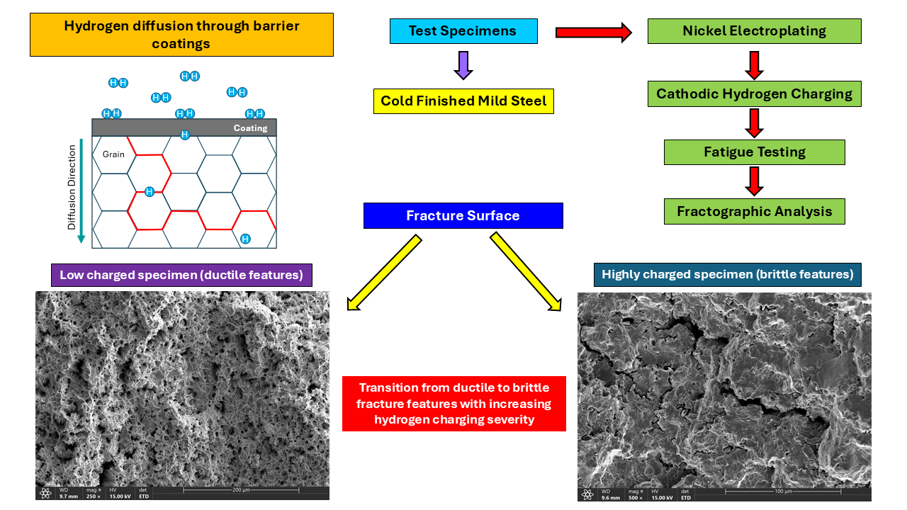
Given the challenges posed by hydrogen in structural applications, efforts to mitigate hydrogen embrittlement have become an essential part of modern research. Preventing hydrogen from entering the metal at the initial stages is often more effective than attempting to manage the damage once it occurs. This has led to increasing interest in surface modification techniques, particularly the use of protective coatings known as hydrogen barrier coatings (HBCs). These coatings serve as barriers that impede or slow down the ingress of hydrogen, thereby preventing hydrogen induced damages and preserving the mechanical integrity of metallic components. The process of hydrogen permeation through coatings typically occurs through a sequence of surface interactions and diffusion mechanisms. At the outset, molecular hydrogen (H2) is adsorbed on the coating surface, where it subsequently dissociates in atomic hydrogen and diffuses through the coated layer. Without an effective barrier, these hydrogen atoms continue migrating into the underlying metal substrate. Within the metal, hydrogen tends to collect at microstructural defects such as grain boundaries, vacancies, and dislocations – sites that serve as trapping regions to facilitate embrittlement [27]. The conceptual framework for the mechanism of hydrogen permeation through barrier coatings is contextualized in a review by Rönnebro et al. [28] providing a detailed description of the permeation process. Coating materials characterized by densely packed crystal structures and chemically strong bonds, such as metallic and ceramic coatings, functionally hinder the diffusion of hydrogen atoms by requiring significant energy to disrupt their stable bonding configuration. Furthermore, coatings barriers with an adequate density of structural defects, such as vacancies or pores, act as potential trap sites that capture hydrogen atoms, inhibiting their continued transport into the underlying substrate [29].
Ceramic, polymeric, and metallic coatings are among the coating types being explored as suitable HBCs. Ceramic coatings offer good chemical stability and low hydrogen permeability, making them effective diffusion barriers. However, their intrinsic brittleness and tendency to crack under mechanical or thermal stresses can compromise long-term usage, especially for components subjected to cyclic loading [30,31]. Polymeric coatings are advantageous for their lightweight and versatility, though their limited mechanical robustness hampers their application [32]. Metallic coatings, on the other hand, offer a good balance between mechanical durability, cost, and process compatibility [33], making them ideal candidates for further exploration as barrier coatings to limit hydrogen uptake. Few metals possess low hydrogen permeability properties to be employed as effective hydrogen barriers. Among these are nickel-based coatings. The appeal for nickel coatings lies in their favorable balance between cost, ease of deposition, chemical stability, corrosion resistance, and low hydrogen diffusivity [34]. Incorporating a nickel-rich interlayer within multilayered coatings has been shown to effectively reduce hydrogen ingress in high strength steels [35]. From a variety of deposition techniques, electroplating is a commonly utilized method to deposit nickel coatings onto metallic substrate. The effectiveness of electroplated coatings, however, is highly dependent on factors such as, surface preparation, bath composition, current density, temperature, and post-plating treatments, as these parameters influence coating uniformity, defect density, and adhesion quality. A notable concern also is that the electroplating process itself can introduce hydrogen into the substrate through electrochemical reactions, potentially offsetting its intended protective function. To mitigate this, post-plating heat treatment, such as baking – which involves subjecting the coated material to very high temperatures – is applied to promote hydrogen desorption from the metal [36].
Extensive research has been devoted to understanding HE and its impact on metallic materials. However, the synergistic interaction between hydrogen exposure and fatigue behavior warrants further research. This knowledge is especially relevant in hydrogenated environments where structural materials are subjected to cyclic loading conditions during service, such as those experienced by pipelines and pressure vessels. These environments simultaneously foster hydrogen-induced degradation and fatigue damage which poses a serious challenge to structural reliability. With growing interest in mitigating the adverse effects of hydrogen through the use of barrier coatings, existing research on nickel in this context is largely focused on nickel alloy and composite coatings while the efficacy of pure nickels coatings as hydrogen diffusion barriers remains comparatively underexplored. Given the industrial relevance of low-carbon steels for various structural applications, this study aims to evaluate the effectiveness of electroplated nickel coatings in mitigating hydrogen embrittlement while also assessing their influence on fatigue performance under cyclic loading conditions. The findings in the study would also support the literature on the design of protective coatings for hydrogen-exposed infrastructures.
2. Experimental Methods
2.1. Material
The material used in this study was cold-finished mild steel (AISI 1018) shaped in the form of standardized coupons. These coupons were produced from commercially supplied stock material and finished to the target dimensions as shown in Figure 1. The specimens were machined with fine-tolerance control to achieve uniform geometry and surface smoothness, ensuring consistency among test samples.
To verify the material’s conformity with the designated steel grade and to establish a baseline for subsequent analysis, a series of characterization procedures were carried out to determine its chemical composition, microstructure, and crystalline structure. The chemical composition of the material was analyzed using the inductively coupled plasma mass spectrometry (ICP-MS), a technique that is capable of detecting trace elemental constituents in a sample matrix. This method provided a precise quantitative assessment of the alloying elements present in the steel. The measured material composition is summarized in Table 1 below.
Microstructural and morphological examinations of the test sample was performed using scanning electron microscopy (SEM). Prior to imaging, specimens were sectioned and mounted in epoxy resin and then metallographically prepared through sequential grinding and polishing steps according to standards outlines in ref. [37]. The grinding process was done using silicon carbide abrasive papers with progressively finer grit sizes (240, 320, 400, 600, and 800), followed by polishing with 1µm and 0.3µm alumina suspension polishing liquid to achieve a mirror-like finish. Etching was then carried out using a natal solution to reveal the microstructure of the polished specimen.
To verify the material’s crystalline structure, X-ray diffraction (XRD) analysis was performed by using the Bruker D8 Advance X-ray diffraction system. The diffraction scan was conducted over a 2θ range from 20° to 100° with a step size of 0.049°. The resulting spectra were analyzed using an EVA software equipped with a system to identify the crystalline phases in the sample matrix.
The hardness of the material was evaluated using the Rockwell hardness test with the HRB scale. Testing was carried out according to the standard procedures outlined in [38]. The sample surface was prepared to be smooth and clean and then securely positioned on the testing platform of a hardness tester. With the use of a 1/16-inch steel ball indenter, the sample is subjected to a preliminary load of 10kgf, followed by a major load of 100kgf. The hardness values were automatically computed by the testing machine based on the indentation depth after an appropriate dwell time, offering a representative measure of the bulk harness of the steel material.
2.2. Nickel Electroplating
Nickel electroplating was employed to deposit a metallic coating unto the cold-finished mild steel substrates. The plating process operates on the principle of electrolytic deposition, where an external current drives the reduction of positively charged metal ions in an electrolyte onto a cathode surface. In this study, mild steel specimens served as the cathode, while a nickel sheet metal was used as the anode. Both electrodes were immersed in an electrolyte, and a direct current was applied to initiate the electrochemical reactions.
At the cathode, nickel ions in the electrolyte are reduced to metallic nickel according to the expression:
Ni2+ +2e– → Ni
At the anode, metallic nickel is oxidized to nickel ions and is given by the expression:
Ni → Ni2+ +2e–
Hydrogen evolution can also occur as a side reaction:
2H+ + 2e– → H2
Before electroplating, the steel fatigue specimens underwent a meticulous sample preparation procedure to ensure proper adhesion and uniformity of the nickel coating. First, the gauge sections of the test samples were manually ground using silicon carbide abrasive papers and then polished to a surface finish of 3 microns (µm) with the use of a diamond suspension polishing liquid to achieve a smooth surface. The polished specimens were then cleaned with soap and hot water to remove residual polishing particles and surface contaminants. To expel grease and oils, the samples were immersed in a heated alkaline degreasing solution with a composition of 30g/L sodium carbonate (Na2CO3), 30g/L trisodium phosphate (Na3PO4), and 50g/L sodium hydroxide (NaOH), at a temperature of 85℃ for 5 minutes and then rinsed with distilled water. Next, acid pickling was performed to remove oxides and scale. Specimens were placed in a 20% hydrochloric acid (HCL) solution for 60 seconds and then rinse thoroughly in distilled water. Following pickling, surface activation was carried out by dipping the samples into a 10% sulfuric acid (H2SO4) solution for 30 seconds, succeeded by a final rinse in distilled water. This step was essential to enhance surface reactivity prior to plating. The shoulder ends of each test samples were masked with chemical-resistant tape to ensure only the gauge section was coated with nickel. After masking, the specimens were vertically suspended in the electroplating cell with the plating bath kept at a consistent volume of 250ml for all plating experiments.
The experimental setup for the electrodeposition of the nickel coatings is shown in Figure 2. The system consists of a DC power supply which provided constant current to the plating system, an external temperature probe integrated with a digital hotplate device to regulate thermal input to the electroplating cell, a calibrated thermometer to continuously monitor the plating bath’s temperature, and a pH meter to verify the pH of the plating solution. The bath temperature and agitation speed were both controlled through an onboard control unit to ensure consistent conditions throughout the plating process. Inside the cell contained the Watts nickel plating solution, the steel substrate (cathode) and a nickel sheet metal (anode) that encircled the inner wall of the plating cell.
Nickel coatings were deposited on the prepared steel specimens using a standard Watts nickel plating bath. The electrolyte was comprised of nickel sulfate (NiSO4∙6H2O) as the primary source of nickel ions, nickel chloride (NiCl2∙6H2O) to enhance bath conductivity and to promote efficient anode dissolution, and boric acid (H3BO3) as a buffering agent to stabilize the pH of the solution. The bath pH was maintained within the optimal range of 3.5 – 4.5. If necessary, adjustments could be made to the bath pH by adding drops of 25% by volume sodium hydroxide (NaOH) to raise the pH or 10% by volume sulfuric acid (H2SO4) to lower it. The temperature of the electrolyte was maintained between 50 – 60℃. Mild agitation was performed with a magnetic stirrer operating at speeds of 100rpm or less to promote homogenous ion distribution. A constant current density of 25mA/cm2 was applied throughout the deposition process with a plating duration of 1 hour. Upon completion of the electroplating process, the nickel-coated steel specimens were thoroughly rinsed in distilled water to remove any residual chemical from the surface and then air-dried. Figure 3 shows an image of the resulting nickel-coated fatigue specimen. All parameters for the electrodeposition process were controlled and maintained consistently across all plating experiments.
2.3. Electrochemical Hydrogen Charging
Hydrogen was introduced into the nickel-coated fatigue specimens through an electrochemical charging method designed to simulate hydrogenated conditions encountered by steel materials during service. The experimental setup is illustrated in Figure 4. The charging cell contained an aqueous electrolyte composed of 0.1 M sodium hydroxide (NaOH) solution uniformly mixed with 3.3g/L ammonium thiocyanate (NH4SCN) that served as a catalytic poison, preventing the recombination of hydrogen atoms into molecular hydrogen. Before each charging experiment, the steel specimens were cleaned with acetone and covered with chemical-resistant tape, leaving only the nickel-coated gauge section exposed to the electrolyte for electrochemical charging. The test cell was equipped with a pH meter to check the pH, a thermometer to monitor the temperature, and gas valves (inlet and outlet) for purging. The charging cell was hermetically sealed to maintain experimental integrity. Prior to the charging process, argon gas was passed through the inlet valve and into the cell to purge the system and remove oxygen. This is done to ensure an inert medium for the experiment. Hydrogen charging was carried out via galvanostatic control using a potentiostat that supplied a constant current to the electrochemical cell. The applied current facilitated the cathodic evolution of hydrogen on the coated steel surface, prompting atomic hydrogen diffusion into the metal. In the experimental configuration, the nickel-coated steel specimens served as the working electrode, while platinum was used as the counter electrode.
It has been established that hydrogen concentration in electrochemical charging is proportional to the square root of charging current density [39,40,41]. With this, a range of current densities were selected to induce a corresponding range of hydrogen content in the coating which were electrochemically charged for 180 mins. The selected charging conditions are summarized in Table 2.
2.4. Fatigue Testing
Fatigue tests were carried out following the electrochemical hydrogen charging process to evaluate the influence of hydrogen on the fatigue behaviour of the coated mild steel specimens. Cyclic loading of the samples was conducted using a rotating fatigue machine (TecQuipment SM1090V-Nottingham, UK) which operates based on Wӧhler’s principle [42,43]. The setup consists of a main unit and a separate control and instrumentation unit as shown in Figure 5.
The main unit rotates the samples with a constant applied load. In this configuration (Figure 6), a motor drives a coupling and a driveshaft fitted with a collet chuck that grips the specimen with proper concentricity at one end. The opposite side (free end) of the specimen is supported by a self-aligning bearing housed within a gimbal assembly. The gimbal assembly is linked to a loading arm that has a moveable dead weight used to set and apply a vertical load to the specimen. The system is also equipped with an electronic sensor and load cell that records the number of cycles and measures the applied load, respectively. For safety, the machine is equipped with a protective cover that automatically halts the test when opened.
During testing, each specimen is clamped at one end and subjected to a constant load at the free end while rotating at fixed speed. The applied load was determined based on 50% of the material’s yield strength, established from preceding tests and calculated using the standard bending equation for the specimen as a circular cross-section cantilever, given in Equation (4) below. The nickel-coated fatigue specimens were subjected to cantilever loading as shown in Figure 7. This action induces alternating tensile and compressive stresses along the specimen surface, as illustrated in Figure 8, closely replicating the cyclic stress conditions encountered by steel components in service under fluctuating loads.
Where σ is the applied stress, l is the distance from the specimen’s midpoint to the point of load application, F is the applied load, and D is minimum diameter of the gauge area.
Test control and data acquisition were managed through the machine’s control and instrumentation unit, shown in Figure 9, which showed real-time display of the applied load, frequency, and number of cycles. A constant frequency of 60 Hz was applied for all samples, ensuring consistent cyclic loading conditions across all experiments.
3. Results and Discussion
3.1. Microstructure
The X-ray diffraction (XRD) analysis of the nickel-coated, cold-finished mild steel specimen revealed distinct diffraction patterns corresponding to both the electroplated nickel coating and the underlying steel substrate as shown in Figure 10. The diffraction peaks of the nickel layer depicted a face-centered cubic (FCC) crystal structure, characteristic of electroplated nickel coatings and also confirming its crystalline structure. Similarly, peaks corresponding to body-centered cubic (BCC) phases were identified, representing the ferritic structure of the mild steel substrate beneath the coating.
The Rockwell hardness test of the coated specimen yielded an average hardness value of 95.27 HRB. This measured value reflects the combined hardness response of both the steel substrate and the electroplated nickel coating.
Metallographic examination of the mild steel substrate under SEM revealed a microstructure predominantly composed of distinct ferrite and pearlite grains as portrayed in Figure 11. These features are characteristic of low-carbon steels. The ferrite phases appeared as relatively smooth regions, representing the ductile α-iron. In contrast, the pearlite regions were observed as lamellar structures formed by alternating layers of ferrite and cementite (Fe3C) which contributes to the strength and hardness of the steel. Dispersed across the steel material were pre-existing inclusions – impurities originating from the steel making process that become entrapped during solidification. These inclusions are chemically and physically distinct from surrounding matrix and do not deform plastically with the material, hence they act as localized stress concentrators. Under cyclic loading these particles can promote the formation of microvoids or microcracks at stress levels lower than what is required to deform the bulk material which makes them preferential nucleation sites for fatigue cracks that consequently reduces the overall strength and durability of the steel.
Energy dispersive X-ray spectroscopy (EDX) analysis was conducted on selected areas on the observed specimen’s surface, as shown in Figure 12. This analysis was done to provide a comprehensive assessment of the material’s elemental composition. The examination was divided into two parts: region analysis and point analysis. A total of eleven different locations were analyzed, with regions 1 through 4 representing broader area scans to determine the overall compositional distribution across larger zones. Points 1 through 7, on the other hand, were selected for precise evaluation of elemental constituents at specific points, particularly around inclusions and other microstructural features.
Table 3 presents the summary of the EDX analysis (from points 1 through 4) which were done on the inclusions observed on the sample surface. These points exhibited high contents of manganese (Mn) and sulfur (S), suggesting the presence of manganese sulfide (MnS) inclusions. These particles were likely formed during the steelmaking process where sulfur reacts with manganese during solidification. Moreover, the presence of these inclusions can also create localized strain incompatibilities within the steel matrix. Under cyclic loading, these sites act as stress concentrators that can promote the formation of cracks.
Further analysis of the sample revealed a matrix consisting of both ferrite and pearlite grains (Table 4). Points 5 through 7, were dominated by carbon (C) and iron (Fe) which suggests the presence of the pearlite phase. This composition aligns with the characteristic lamellar structure of pearlite, which improves the material’s strength and toughness through the alternating arrangement of hard cementite (Fe3C) and softer ferrite phases. Similarly, regions 1 through 4 were mostly dictated by higher iron (Fe) content, confirming that these areas correspond to the ferritic phase of the steel sample.
SEM examination of the cross-section of the nickel-coated specimen revealed a uniform and dense coating morphology that is well adhered to the steel substrate as shown in Figure 13a. The nickel layer had an average thickness of approximately 40 μm (microns) and appeared continuous and free of visible defects. A well-defined interface between the coating and the steel substrate was observed, implying adequate metallurgical bonding during the electroplating process. EDX elemental mapping of the observed cross-section further distinguished the nickel coating from the underlying steel substrate (Figure 13b), showing a strong composition of nickel on the coated layer, while the substrate region was dominated by iron (Fe). Trace elements including carbon (C), manganese (Mn), sulfur (S), and silicon (Si) were also detected (Figure 14) which were consistent with the alloying elements in the mild steel material.
3.2. Fatigue Response to Varying Charging Current Densities
The fatigue response of the nickel-coated, cold-finished mild steel specimens in this study exhibited a non-monotonic trend between fatigue life and varying hydrogenating conditions, quantified in terms of the charging current densities. These results are shown in Figure 15.
Initially, at low charging current densities – corresponding to low levels of hydrogen content – the number of cycles to failure decreased slightly. As the charging current density rose into the moderate range, a pronounced increment in fatigue life is observed. Whereas, at much higher charging current densities, fatigue life declined abruptly as demonstrated by the decreasing number of loading cycles. The overall trend in fatigue behavior underscores the competing influences of HE mechanisms and also highlights the effectiveness and limitation of the electrodeposited nickel coating as a probable diffusion barrier to impede hydrogen ingress under cyclic loading.
In the uncharged condition, the fatigue response of the coated steel specimen primarily reflects its mechanical behavior in the absence of induced hydrogen (0.00 mA/cm2), establishing a baseline for evaluating the effects of hydrogen permeation. At low charging current densities (from 0.16 to 2.49 mA/cm2), the specimens exhibited a slight reduction in fatigue life as the number of loading cycles to failure mildly plummets. The magnitude of this decline appears modest; however, it shows the tendency of trace amounts of absorbed hydrogen to alter the mechanical traits of the metal under cyclic loading [44]. During electrochemical hydrogen charging, atomic hydrogen is generated at the sample surface through the cathodic reduction of hydrogen ions in the electrolyte. Adsorbed hydrogen atoms from the electrolytic reaction attempt to diffuse through the coating and permeate into the underlying steel substrate. The electrodeposited nickel layer, by design, is intended to slow down this process by acting as a diffusion barrier to minimize hydrogen ingress. In practice, however, coatings deposited via electroplating can sometimes incur microscopic imperfections, such pores, thin regions, or grain boundary networks, that can provide a potential pathway for localized hydrogen transport [45]. As a result, though the coating significantly limits overall hydrogen permeation, a fraction of atomic hydrogen may still penetrate through these discontinuities which can influence the fatigue behavior of the metal in the low-hydrogen regime.
Hydrogen atoms that are able to bypass the nickel coating tend to localize and interact with microstructural features within the steel, such as dislocations, vacancies, grain boundaries, and interstitials. These features also serve as hydrogen traps that capture hydrogen at specific regions within the metal structure. Hydrogen traps can be categorized based on their binding energy and they can either mitigate or exacerbate embrittlement depending on their nature. Traps with high binding energy, termed as irreversible traps, can sequester hydrogen and limits its mobility in the lattice once trapped. Hydrogen atoms bonded in these traps do not severely contribute to embrittlement. Moreover, a high temperature is needed for hydrogen to be released from such traps since hydrogen trapping or de-trapping is a thermally activated process [46]. Low-energy “reversible” traps release hydrogen more easily which can facilitate hydrogen redistribution to stress-concentrated regions that can further promote embrittlement. The intricate balance between diffusion and trapping strongly dictates the rate at which hydrogen concentrates and also influences the material’s susceptibility to degradation. From the results in this study, the mechanical impact of hydrogen traps appears to be more detrimental within low charging current densities. Localized accumulation of hydrogen in the material’s microstructure essentially reduces the cohesive strength of metallic bonds through the mechanism known as hydrogen-enhanced decohesion (HEDE) [10]. In this process, absorbed hydrogen weakens the atomic bonds that hold the metal together, prompting bond breakage and lowering the energy required for atomic planes to separate. This action facilitates the formation of microcracks at existing weak points in the microstructure, like inclusions, that serve as stress concentrators under cyclic forces. With progressive cyclic loading, these microcracks can grow more readily due to continued hydrogen-assisted bond weakening at the crack tip. The cumulative effect of these interactions accelerates crack propagation and results in reduced fatigue life which is reflected by the number of cycles to failure observed at low charging current densities.
Around moderate charging current densities (from 9.99 to 39.99 mA/cm2), the fatigue response of the material completely shifts as the number of loading cycles to failure increases, signifying a notable improvement in fatigue life. In this domain, a greater content of hydrogen is introduced to the specimen, however, much of it is immobilized at various trap sites rather than remaining completely diffusible. This is largely due to the hydrogen diffusivity of nickel which is several orders of magnitude lower than steel [47,48,49]. For metals with BCC structures, such as low carbon steels, interstitial hydrogen atoms preferentially move from one tetrahedral site to another rather than through octahedral sites [50,51]. Conversely, in FCC metals, like nickel, hydrogen atoms tend to occupy octahedral interstitial sites, which characteristically have lower multiplicity for hydrogen migration [52]. As a result, the nickel-coated layer plays an active role in augmenting the diffusion behavior of hydrogen. At moderate charging current densities, the nickel coating becomes partially saturated with hydrogen, forming a concentration gradient that limits the rate at which hydrogen enters the substrate. This quasi-saturation effect functionally transforms the coating into a hydrogen sink, where absorbed hydrogen remains confined within the nickel coated layer rather than freely diffusing into the steel. Practically, a high density of hydrogen sinks is desired for barrier coatings because they diminish the content of diffusible hydrogen and reduce the risk of hydrogen embrittlement [53]. The ability of the coating to amplify the energy barrier and diffusion length for hydrogen migration crucially suppresses the concentration of mobile hydrogen available to accumulate at critical stress zones such as crack tips.
Furthermore, residual compressive stresses introduced by the electroplating process could also potentially complement the gain in fatigue response. Electrodeposited nickel coatings commonly possess internal compressive stresses that develop due to lattice mismatch, microstructural refinement, and deposition conditions from the plating process [54]. As the coated specimen is subjected to cyclic loading, these residual stresses may act beneficially by counteracting part of the externally applied tensile stress during the fatigue cycle. From fatigue loading, stresses alternate between tension and compression, however, the compressive bias from the coating minimally reduces the effective tensile stress amplitude. This suppression of peak tensile stress helps delay crack sprouting to an extent, which assists in prolonging the fatigue life of the material [55].
Within this same range of charging current densities, hydrogen atoms that manage to reach the steel substrate may also contribute to the improved fatigue response through the mechanism known as hydrogen-enhanced localized plasticity (HELP). The HELP mechanism describes how the presence of hydrogen within the metal microstructure alters dislocation behavior by reducing interaction energies [56]. In metals, dislocations encounter resistance as the move through the crystal lattice due to interactions with other dislocations, solute atoms, or precipitates. However, hydrogen reduces the interaction energy between these obstacles, allowing dislocations to glide more easily along slip paths where the barriers are lowest. This enhanced mobility allows dislocations to pile up in confined regions rather than being uniformly distributed throughout the material, creating concentrated zones of localized plastic deformation. These areas act somewhat as internal buffers that accommodate cyclic strain more effectively than the surrounding matrix. By allowing dislocations to move and rearrange within specific regions, the material can relieve local stress concentrations that might otherwise accumulate at microstructural defects. In this manner, the HELP mechanism contributes subtly to the steels mechanical response under cyclic loading, redistributing stresses away potential crack initiation sites. The result is a material that exhibits improved toughness and fatigue resistance within this intermediate hydrogen regime.
It is important to highlight that this beneficial effect is conditional and only persist within a narrow range of hydrogen exposure. At moderate charging current densities, the balance between hydrogen trapping in the coating, compressive residual stresses, and localized plasticity is optimal. Under these conditions, hydrogen facilitates dislocation motion without promoting extensive embrittlement. However, once the hydrogen concentration surpasses this threshold, localized plastic deformation becomes excessive which immensely accelerate crack initiation and ultimately diminishes fatigue life.
At higher charging current densities (ranging from 62.48 to 249.93 mA/cm2), the nickel-coated mild steel exhibits a clear decline in fatigue life as the number of cycles to failure drops abruptly. This deterioration in mechanical response stems from a combination of several factors that collectively promote embrittlement in the material. During both the electroplating and electrochemical charging processes, hydrogen is produced at the metal surface as a resulting product of cathodic reactions. Generally, plating processes have a cathode current efficiency of less than 100% because a proportion of the current supplied to the plating system goes towards hydrogen evolution, where hydrogen ions in the electrolyte are reduced to atomic hydrogen [57]. A major portion of the generated hydrogen recombines and evolves as molecular hydrogen (H2); however, some fraction can become trapped at the coating-substate interface or become occluded with the forming nickel deposits through a process known as hydrogen occlusion [58,59]. This occluded hydrogen potentially creates a stored source of subsurface hydrogen that exist prior to the charging process. At low charging conditions, residual hydrogen confined within the coating interface exerted minimal impact on the fatigue behavior of the metal. However, at much higher charging potentials, its effect becomes more pronounced as it supplements the hydrogen introduced during the charging process which substantially raises the overall concentration of hydrogen within the material. As external charging intensifies, more hydrogen atoms is introduced to the specimen and they attempt to diffuse through the coating. The nickel layer slows down this operation; however, it is not completely impermeable, especially with more aggressive charging conditions where the driving force for hydrogen ingress is high. Microscopic imperfections within the coating can also provide pathways for hydrogen to easily diffuse. Once the hydrogen flux increases beyond a certain threshold than what the coating can effectively contain, a high content of hydrogen is able to reach and permeate into the steel substrate.
Once inside the steel, hydrogen migrates to microstructural defects such as dislocations, vacancies, and grain boundaries, which basically act as traps that temporarily immobilizes its free movement [60]. At moderate hydrogen levels, these traps helped delay embrittlement by capturing hydrogen and hindering it from freely diffusing into the lattice as inferred from the steel’s mechanical response. However, as hydrogen content increases with higher charging current densities, these traps progressively fill up and eventually reach saturation. Once saturated, they can no longer accommodate additional hydrogen, leaving the surplus hydrogen in a mobile, diffusible state. Mobile hydrogen in the microstructure of the steel is detrimental because it can travel towards regions of high stress, such as crack tips or inclusion interfaces, where it destabilizes atomic bonds and promotes fracture. As a result, the HEDE phenomena becomes dominant. In this mode of embrittlement, hydrogen reduces the cohesive strength of atomic bonds within the metal lattice, making it easier for atomic planes to separate. During cyclic loading, where the coated steel specimen is repeatedly stretched and compressed, the loss in cohesive bonding strength in the metal’s microstructure dramatically lowers the stress required for cracks to initiate. The presence of hydrogen at the crack tip further accelerates crack propagation as hydrogen collects preferentially in such highly stressed areas. Consequently, cracks initiate earlier and extend faster then they would in a non-embrittled metal. In addition, at very high hydrogen levels, atomic hydrogen (H) can recombine into molecular hydrogen (H2) at microdefects within the steel. Owing to the fact that H2 cannot diffuse through the metal, its recombination inside the steel forms internal pressures that foster microvoid expansion and internal cracking [17]. This process, often described as hydrogen-induced cracking, acts synergistically with decohesion to amplify embrittlement. These results obtained for the coated specimens align closely with those reported by researchers in [61].
In a similar fatigue study, researchers examined the fatigue behavior of cold-finished mild steel specimens across varying hydrogen concentrations [62], using experimental parameters comparable to those employed in this present work. The specimens in this study were without coating barriers, so the introduction of hydrogen was more direct. Their findings revealed a trend that was essentially the reverse outcome of what was observed for the nickel-coated specimens in this study. For the uncoated steel, HEDE dominated the fatigue response at low to moderate hydrogen concentrations, leading to a reduction in fatigue life. At higher hydrogen levels, the HELP mechanism was more influential, resulting in a partial recovery or stabilization of fatigue performance. In contrast, the nickel-coated steel specimens examined in this study exhibited a distinct sequence of governing mechanisms, HELP contributed to improved fatigue life at moderate concentrations, while HEDE was most dominant at higher levels where hydrogen content became more excessive. The differing outcomes of both studies highlight the role of surface engineering in influencing fatigue behavior. More importantly, they underscore the need for continued scientific refinement in understanding how coatings, hydrogen uptake, and microstructural interactions collectively shape embrittlement mechanisms.
Figure 15 also presents the plot of the time to failure versus charging current densities which closely mirrored the trend in the number of cycles to failure as a function of charging current densities. This correspondence is expected because under constant load and fixed testing frequency, the number of loading cycles to failure and time to failure is directly proportional, resulting in identical plots.
3.3. Fracture Surface Analysis
3.3.1. Uncharged Specimen
Examination of the fracture surface of the uncharged (0.00mA/cm2), nickel-coated specimen, revealed features such as dimples, microvoids, and microcracks that collectively describe a ductile failure process as shown in Figure 16.
Coating buckling was observed along the specimen’s edge (Figure 16a), adjacent to the main fracture zone. This feature appeared as a raised, semi-circular protrusion of the coated layer, highlighting a region where the coating separates from the steel substate. The formation of the buckled coating is closely linked to the mechanical mismatch between the brittle nickel coating and the more ductile steel substrate during cyclic loading. Under repeated tension-compression cycles, the steel material undergoes plastic deformation, while the nickel coating, being relatively stiff, doesn’t accommodate the same level of strain as the underlying substrate. As the steel deforms, compressive stresses gradually build up within the nickel layer. Over several loading cycles, these stresses could exceed a critical level where the coating is unable to maintain adhesion to the substrate. To relieve this stress, the coated layer detaches and bends outward, forming a buckled profile.
Beneath the buckled coating, the exposed substrate displayed wrinkling patterns which manifested as wavy, undulating lines along the edge of fractured cross-section. These wrinkles develop as the steel material deforms relative to the constrained surface condition created by the coated layer. As fatigue cracks propagate with repeated cyclic loading, this causes small-scale localized plastic deformation to accumulate around an advancing crack tip which forms these ripple patterns that are commonly oriented perpendicular to direction of crack growth. The presence of these wrinkles accentuates the ductile nature of steel material, as it absorbs and redistributes cyclic stresses before final fracture.
Observed rachets marks were distinct, linear features that appeared as step-like ridges on the fracture surface (Figure 16b). These features form when multiple microcracks nucleate independently and subsequently coalesce into a single dominant crack front. During cyclic loading, subtle variations in local stress, microstructural heterogeneities, or surface imperfections can cause fatigue cracks to initiate at more than one site along the specimen edge. As these cracks propagate, they move towards each other, growing at slightly different rates and orientations under cyclic loading. When these cracks eventually intersect, the mismatch creates visible step-like features that depicts the merging of these individual cracks into a unified propagation path. These features illustrate fatigue crack propagation from multiple initiation sites, dictated by the applied stress amplitude. Their orientation typically aligns parallel to the direction of crack growth and radiates towards the final rupture zone.
Further examination of the fracture surface of the specimen revealed features associated with ductile overload, most notably the presence of dimples and microvoids. Dimples occupied a large area of the final fracture region, appearing as small, rounded depressions on the fracture surface. Each dimple corresponds to the site of a microvoid that formed during the latter stages of fracture. In ductile materials, such as mild steel, microvoids typically nucleate at inherent microstructural discontinuities – most commonly inclusions, second-phase particles, or regions of local stress concentration. During cyclic loading, these microvoids grow with continued plastic deformation and eventually coalesce with other surrounding voids to form the dimpled morphology. The presence of dimples is indicative of significant plastic deformation prior to final rupture. The size and distribution of the observed dimples provide insights on the nature and conditions to which the material failed. Larger dimples denote sites where inclusions or second-phase particles were present, whereas smaller dimples represent more homogeneous regions of the steel material.
Embedded on the fracture surface were also inclusions in the form of irregularly shaped particles that are mechanically distinct from the steel matrix. The features are stress raisers that serve as preferential sites for void initiation due to the weaker mechanical bond they have with the surrounding steel matrix. Inclusions significantly influences the fatigue behavior of the metal by either amplifying local stresses or facilitating debonding of interfaces under cyclic loading. As a result, they become primary nucleation sites for microvoids and microcracks. Microcracks were visibly evident across various regions of the fractured cross-section. Generally, these cracks form in regions where the local stress exceeds the metal’s ability to accommodate cyclic deformation, especially around inclusions. Once initiated, these cracks grow incrementally with repeated cyclic loading, following paths of least resistance through the microstructure. Their presence is indicative of the propagation phase of fatigue failure, before the formation of larger, dominant cracks that ultimately leads to final rupture.
3.3.2. Low to Moderately Charged Samples
Analysis of the nickel-coated specimens subjected to low and moderate charging current densities (i.e, from 0.16 to 39.99 mA/cm2) revealed a combination of ductile and brittle fatigue features as shown in Figure 17. This mixed fracture response reflects the interplay of hydrogen embrittlement mechanisms and the intrinsic mechanical traits of the steel material under cyclic loading.
The fracture surface of a low-charged nickel-coated specimen tested at a current density of 2.49mA/cm2 showed a clear partition of the fatigue fracture process into distinct regions (Figure 17a) namely, the crack propagation zone, the unstable crack growth region, and the final ductile overload zone. The crack propagation zone occupies a major portion of the fractured cross-section and shows the region were the fatigue crack advances incrementally with successive loading cycles. This area is marked by a relatively flat topology that reflects the progression of fatigue crack in a fairly stable manner governed primarily by local stress intensity. Along the propagation path, i.e., between the crack propagation zone and ductile overload region, a transitional band exists where quasi-cleavage facets and secondary cracks are evident (Figure 17c). Quasi-cleavages manifest as partially faceted surfaces that lack the full crystallographic appearance of true cleavages but are noticeably less ductile than the surrounding matrix. Their occurrence points to the localized embrittling influence of hydrogen through the HEDE mechanism. At low charging conditions, the amount of hydrogen able to bypass the nickel coated layer may be limited but still sufficient to weaken the cohesive strength of atomic bonds in the steel, especially in regions where hydrogen accumulation is favoured by stress gradients or microstructural heterogeneities. The distribution of hydrogen may also be uneven such that certain regions with higher content of hydrogen exhibit more brittle behaviour compared to other areas of the material. As crack growth proceeds, hydrogen accumulates near the crack tip, lowering the stress required to separate atomic planes and prompting the formation of quasi-cleavages. Moreover, the high density of secondary cracks on the fracture surface can be attributed to presence of hydrogen due to its tendency to promote crack branching within the metal’s microstructure.
The unstable crack growth region represents the area where the fatigue crack advances rapidly in an erratic manner. This region is identified by a sudden deviation in the propagation path where the fatigue crack transverses along a lower-energy plane, producing a flat fractured surface with faint striation-like patterns and minimal plastic deformation. Its morphology is indicative of an abrupt crack extension just before the final overload. Hydrogen atoms situated within the metal’s microstructure can intensify local bond weakening which prompts cracks to move through routes with least resistance. The region’s proximity to the final overload zone further alludes that this sudden extension occurred when the remaining material could no longer sustain the applied load.
The ductile overload region signifies the final stage of fracture where the steel material ultimately fails under the accumulated stress (Figure 17b). This region is distinguished by extensive microvoid coalescence, dimples, and significant plastic deformation across the fracture surface and also highlights the metal’s capacity to accommodate substantial plastic strain before failure.
For a moderately charged specimen tested at a charging current density of 24.49mA/cm2, the fracture surface portrayed two distinct regions: a dominant stable zone and a final overload zone as shown in Figure 17d. Notably, at this charging condition, the coated steel specimen exhibited the most improved fatigue life among the tested conditions, achieving the highest number of loading cycles to failure (270,599 cycles). On the fracture surface, the stable zone dominates a major area of the examined cross-section as it depicts the steady progression of crack growth over thousands of loading cycles. Within the stable zone, fatigue striations were identified. These features form as crack advances incrementally with each loading cycle, leaving behind a series of fine, parallel markings that record the cyclic propagation of fatigue crack. Each striation line corresponds to one complete load cycle, and they run perpendicular to the direction of crack propagation.
In some localized areas, particularly near the transition between the stable zone and overload zone, cleavage facets were observed. These flat, mirror-like features reflect patches of brittle fracture that are triggered when fatigue cracks propagate through specific crystallographic planes with little to no plastic deformation due to the influence of hydrogen. Hydrogen atoms that manage to reach the steel tend to accumulate at microstructural interfaces where stresses are elevated, causing isolated regions of the steel to fracture in a more brittle manner during cyclic loading. Microcracks were also visible across various areas on the fracture surface, most of which were found to emanate from microstructural discontinuities, particularly inclusions (Figure 17f). These inclusions not only disrupt the continuity of the steel matrix but also serve as inherent stress raisers around which localized cracking occurs. Moreover, these particles possess mechanical properties that differ from the surrounding ferritic material, leading to elastic and plastic incompatibilities during cyclic loading.
From the image in Figure 17f, EDX point analysis was conducted on four distinct inclusions identified on the fracture surface of the moderately charged sample (24.49mA/cm2) to determine the elemental composition at these locations. The examined points are highlighted with a cross symbol in Figure 18, and their overall composition is summarized in Table 5.
Based on the results of the EDX analysis, the identified inclusions showed high counts of manganese (Mn) with trace amounts of sulfur across all examined locations (from points 1 to 4). The high content of manganese suggests the presence of manganese sulfide (MnS) inclusions which are commonly found in low carbon steels. These compounds get embedded in the metal microstructure during the steel making process. Under cyclic loading, these irregularly shaped particles act as stress concentrators that facilitate debonding and microcrack nucleation. They also significantly diminish fatigue resistance by promoting a more heterogeneous distribution of cracks. Thus, the plastic deformation behavior of inclusions is often dissimilar from that the surrounding metal matrix. As the steel material undergoes cyclic loading, the variation in plasticity between inclusions and the iron phases fosters localized strain incompatibilities. This mismatch generates stress concentrations that triggers the formation microcracks.
In a similar manner to the low-charged sample, the overload zone of the moderately charged specimen depicts that final stage of fracture of the material. This region forms once the remaining load-bearing cross-section can no longer sustain the applied cyclic stresses. The surface of this region exhibits characteristics typical of ductile rupture, such as dimples, that highlight sufficient plastic deformation prior to failure.
3.3.2. Highly Charged Samples
For samples subjected to higher charging current densities (from 62.48 to 249.93mA/cm2), the fracture surface exhibited features that were dominated by brittle fracture characteristics. Under these condition, the fatigue behavior of the highly charged samples differed comparatively from the uncharged and moderately charged specimens, showing the evolution of fracture morphologies with hydrogen charging severity.
Figure 19.
SEM micrographs of highly charged specimen: (a) 249.93mA/cm2 charged specimen (21×); (b) Magnified view of rapid fracture zone (500×); (c) Magnified view of highlighted blue area in (a) (650×).
Figure 19.
SEM micrographs of highly charged specimen: (a) 249.93mA/cm2 charged specimen (21×); (b) Magnified view of rapid fracture zone (500×); (c) Magnified view of highlighted blue area in (a) (650×).
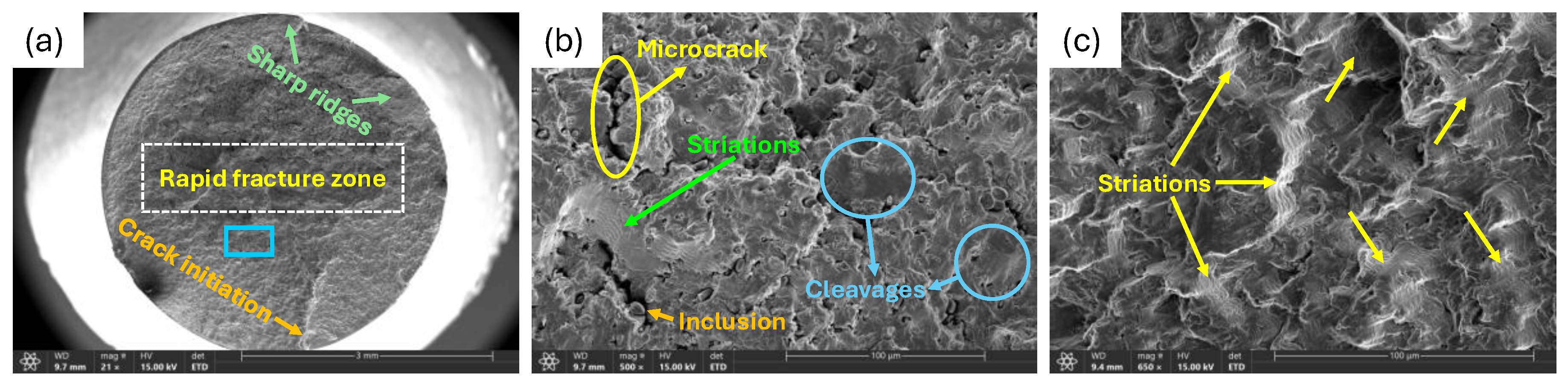
Figure 18 presents the fracture surface of the coated specimen charged with the highest current density tested in this study. The crack initiation site is reminiscent of a rachet-like marking on the surface that is located near the specimen’s edge. This feature indicates that fatigue crack initiated at a specific point of concentrated stresses and propagated inward in small, incremental steps during cyclic loading. Such features are typical of metals where microstructural inhomogeneities, surface irregularities, or residual stresses focus cyclic stresses in discrete zones which prompts the earliest formation of fatigue crack. The step-like appearance of the rachet pattern illustrates repeated, localized advances of the crack front before it transitions to a more rapid growth.
Adjacent to the crack initiation site is the rapid fracture zone. This region is characterized by relatively flat surfaces that depict abrupt crack advancement with minimal plastic deformation and is largely dominated by cleavage facets and microcracks. At high hydrogen charging densities, the steel’s ability to accommodate cyclic plastic deformation is considerably diminished by the presence of hydrogen. Hydrogen accelerates fatigue crack growth rate and augments the brittleness of the material, causing fracture to occur in a relatively brittle manner. Once a critical crack size is reached, the material inevitably fails, leaving behind a surface morphology indicative of brittle, unstable fracture.
Cleavage facets were prominent within the rapid fracture zone. These flat, faceted surfaces show that fracture progressed preferentially along low-energy crystallographic planes with minimal plastic blunting at the crack tip. They also highlight localized brittle fracture through the steel’s microstructure, as crack propagates along weakened planes. These brittle features observed on the fracture surface are directly linked to the HEDE mechanism facilitated by hydrogen. As discussed in section 3.2, at higher charging current densities, the nickel coating is unable to effectively shield the steel substrate from the ingress of hydrogen. As a result, hydrogen atoms adsorb and diffuse into the material, accumulating at stress concentration sites such as dislocation cores and grain boundaries where they reduce the cohesive strength of atomic bonds within the metal, making it easier for bonds to separate under stress. This results in a material that fails with little to no plastic deformation, leading to a pronounced brittle fracture behavior.
Despite the predominance of brittle features, fatigue striations were still observed on the fractured cross-section, serving as precursors for the incremental growth of fatigue crack. These microscopic markings form due to repeated cycles of localized plastic deformation and are typically oriented perpendicular to the direction of crack propagation. The lines on these features commonly develop with consistent spacing between them with each striation line often corresponding to a single load cycle. The presence of diffused hydrogen within the metal microstructure makes striations more distinct due to the increased crack growth rate and brittle nature of the fracture process.
Along the edges of the fracture surface, sharp ridges were evident which suggest unstable changes in crack growth direction during the latter stages of fatigue failure. These ridges develop when different segments of the fatigue crack move at unequal rates or planes, forming step-like offsets in fracture height that remain visible after fracture. In fatigue specimens, these features take shape near free surfaces where stress gradients are elevated and crack growth is less constrained. Due to the impact of hydrogen, cracks are able to deviate along weakened planes with lower resistance which results in local variation in crack paths. Consequently, crack propagation becomes less uniform across the bulk steel material, producing step-like ridges that denote a more brittle mode of fracture.
4. Conclusions
This study examined the fatigue behavior of nickel-coated, cold-finished mild steel specimens subjected to a range of hydrogen charging current densities to assess their response and susceptibility to HE. The charging current densities employed directly correlates to different concentrations of induced hydrogen content in the coated material. The findings provided valuable insights on the effectiveness and limitations of nickel-based coatings as diffusion barriers to impede hydrogen ingress under cyclic loading conditions. The results of this investigation are as follows:
- The number of cycles to failure initially declined with increasing charging current densities, falling from 145,974 for the uncharged nickel-coated sample (0.00mA/cm2) to 129,870 cycles for a low-charged sample at a current density of 2.49mA/cm2. This modest reduction in fatigue performance highlights the tendency of hydrogen to alter the mechanical traits of the metal.
- At moderate charging levels, the coated specimens exhibited an increase in fatigue life, reaching the peak number of cycles to failure at 270,599 cycles. This improvement in fatigue response points to the barrier effect of the nickel coating which limits the flux of hydrogen reaching the steel and prolongs the life of material during cyclic loading.
- At higher charging current densities, the fatigue performance shifts completely as the number of loading cycles to failure reduced steadily, dropping to a minimum of 62,494 cycles. This abrupt decline in fatigue life suggests a threshold behavior beyond which the protective capabilities of the nickel coating degrades and coated layer is no longer able to effectively shield the underlying steel from the permeation of hydrogen. At this stage, HE significantly augments the material’s behavior with the dominate mechanism being HEDE which weakens the atomic bonds of the metal, lowering the stress required for cracks to initiate and ultimately resulting to premature failure.
- Fractographic analysis supported these findings, portraying a clear transition in fracture characteristics with increasing charging severity. The uncharged sample exhibited predominately ductile fracture features characterized by dimpling and microvoid coalescence which is indicative of the material’s capacity for plastic deformation. For samples charged with low to moderate charging current densities, the fracture surfaces showed a mixed mode of fracture with both ductile and brittle features, such as dimples, microvoids, quasi-cleavages, secondary cracks and fatigue striations, all of which suggest partial hydrogen diffusion. Highly charged samples, however, were dominated by brittle fracture features such as cleavage facets, sharp ridges, rapid fracture zones, and widespread microcracking. Overall, these observations demonstrate that while nickel coatings can provide ample resistance to hydrogen induced degradation, their effectiveness is heavily influenced by level of hydrogen exposure.
Author Contributions
Conceptualization, Z.F. and M.M.A.; methodology, M.M.A.; validation, Z.F.; formal analysis, M.M.A. and Z.F.; investigation, M.M.A. and Z.F.; resources, M.M.A. and Z.F.; data curation, M.M.A.; writing—original draft preparation, M.M.A.; writing—review and editing, M.M.A. and Z.F.; visualization, M.M.A. and Z.F.; supervision, Z.F.; project administration, Z.F.; funding acquisition, Z.F. All authors have read and agreed to the published version of the manuscript.
Funding
This research was funded by the Natural Sciences and Engineering Research Council of Canada (NSERC), grant number RGPIN 05125-17.
Data Availability Statement
The original contributions presented in the study are included in the article; further inquiries can directed to the corresponding author.
Conflicts of Interest
The authors declare no conflicts of interest.
Abbreviations
The following abbreviations are used in this manuscript:
| AIDE | Adsorption-Induced Dislocation Emission |
| AISI | American Iron and Steel Institute |
| BCC | Body-Centered Cubic |
| EDX | Energy Dispersive X-ray |
| FCC | Face-Centered Cubic |
| HBC | Hydrogen Barrier Coatings |
| HE | Hydrogen Embrittlement |
| HEDE | Hydrogen-Enhanced Decohesion |
| HELP | Hydrogen-Enhanced Localized Plasticity |
| HESIV | Hydrogen-Enhanced Strain-Induced Vacancy |
| HIPT | Hydrogen-Induced Phase Transformation |
| HPT | Hydrogen Pressure Theory |
| ICP-MS | Inductively Coupled Plasma Mass Spectrometry |
| SEM | Scanning Electron Microscopy |
| XRD | X-Ray Diffraction |
References
- Algburi, S.; Al-Dulaimi, O.; Fakhruldeen, H.F.; Khalaf, D.H.; Hanoon, R.N.; Jabbar, F.I.; Hassan, Q.; Al-Jiboory, A.K.; Kiconco, S. The Green Hydrogen Role in the Global Energy Transformations. Renewable and Sustainable Energy Transition 2025, 8, 100118. [Google Scholar] [CrossRef]
- Nicoletti, G.; Arcuri, N.; Nicoletti, G.; Bruno, R. A Technical and Environmental Comparison between Hydrogen and Some Fossil Fuels. Energy Convers. Manag. 2015, 89, 205–213. [Google Scholar] [CrossRef]
- Akhtar, M.U.S.; Asfand, F.; Mishamandani, A.S.; Mishra, R.; Khan, M.I. Hydrogen as a Sustainable Combustion Fuel: Performance, Challenges, and Pathways for Transition to Low-Carbon Propulsion Systems. Renewable and Sustainable Energy Reviews 2025, 223, 116004. [Google Scholar] [CrossRef]
- Li, X.; Ma, X.; Zhang, J.; Akiyama, E.; Wang, Y.; Song, X. Review of Hydrogen Embrittlement in Metals: Hydrogen Diffusion, Hydrogen Characterization, Hydrogen Embrittlement Mechanism and Prevention. Acta Metallurgica Sinica (English Letters) 2020 33:6 2020, 33, 759–773. [Google Scholar] [CrossRef]
- The Effect of Occluded Hydrogen on the Tensile Strength of Iron. Proceedings of the Royal Society of London. Series A, Containing Papers of a Mathematical and Physical Character 1926, 112, 182–195. [CrossRef]
- Djukic, M.B.; Bakic, G.M.; Sijacki Zeravcic, V.; Sedmak, A.; Rajicic, B. The Synergistic Action and Interplay of Hydrogen Embrittlement Mechanisms in Steels and Iron: Localized Plasticity and Decohesion. Eng. Fract. Mech. 2019, 216, 106528. [Google Scholar] [CrossRef]
- Robertson, I.M. The Effect of Hydrogen on Dislocation Dynamics. Eng. Fract. Mech. 2001, 68, 671–692. [Google Scholar] [CrossRef]
- Birnbaum, H.K.; Sofronis, P. Hydrogen-Enhanced Localized Plasticity-a Mechanism for Hydrogen-Related Fracture. Materials Science and Engineering: A 1994, 176, 191–202. [Google Scholar] [CrossRef]
- Lynch, S.P. Hydrogen Embrittlement (HE) Phenomena and Mechanisms. Stress corrosion cracking: Theory and practice 2011, 90–130. [Google Scholar] [CrossRef]
- Li, Q.; Ghadiani, H.; Jalilvand, V.; Alam, T.; Farhat, Z.; Islam, M.A. Hydrogen Impact: A Review on Diffusibility, Embrittlement Mechanisms, and Characterization. Materials 2024, Vol. 17 17, 965. [Google Scholar] [CrossRef] [PubMed]
- Nagumo, M. Hydrogen Related Failure of Steels - a New Aspect. Materials Science and Technology 2004, 20, 940–950. [Google Scholar] [CrossRef]
- Narita, N.; Birnbaum, H.K. On the Role of Phase Transitions in the Hydrogen Embrittlement of Stainless Steels. Scripta Metallurgica 1980, 14, 1355–1358. [Google Scholar] [CrossRef]
- Han, G.; He, J.; Fukuyama, S.; Yokogawa, K. Effect of Strain-Induced Martensite on Hydrogen Environment Embrittlement of Sensitized Austenitic Stainless Steels at Low Temperatures. Acta Mater. 1998, 46, 4559–4570. [Google Scholar] [CrossRef]
- Dwivedi, S.K.; Vishwakarma, M. Hydrogen Embrittlement in Different Materials: A Review. Int. J. Hydrogen Energy 2018, 43, 21603–21616. [Google Scholar] [CrossRef]
- Dwivedi, S.K.; Vishwakarma, M. Effect of Hydrogen in Advanced High Strength Steel Materials. Int. J. Hydrogen Energy 2019, 44, 28007–28030. [Google Scholar] [CrossRef]
- Martin, M.L.; Connolly, M.J.; Delrio, F.W.; Slifka, A.J. Hydrogen Embrittlement in Ferritic Steels. Appl. Phys. Rev. 2020, 7, 10.1063/5.0012851. [Google Scholar] [CrossRef] [PubMed]
- Chowdhury, M.F.W.; Tapia-Bastidas, C. V.; Hoschke, J.; Venezuela, J.; Atrens, A. A Review of Influence of Hydrogen on Fracture Toughness and Mechanical Properties of Gas Transmission Pipeline Steels. Int. J. Hydrogen Energy 2025, 102, 181–221. [Google Scholar] [CrossRef]
- Salvati, E. Evaluating Fatigue Onset in Metallic Materials: Problem, Current Focus and Future Perspectives. Int. J. Fatigue 2024, 188, 108487. [Google Scholar] [CrossRef]
- Park, J.Y.; Park, Y.C.; Kim, H.K. A Methodology for Fatigue Reliability Assessment Considering Stress Range Distribution Truncation. International Journal of Steel Structures 2018, 18:4 18, 1242–1251. [Google Scholar] [CrossRef]
- Kumar, D.; Idapalapati, S.; Wang, W.; Narasimalu, S. Effect of Surface Mechanical Treatments on the Microstructure-Property-Performance of Engineering Alloys. Materials 2019, 12, 2503. [Google Scholar] [CrossRef]
- Čanžar, P.; Tonkovi?, Z.; Kodvanj, J. Microstructure Influence on Fatigue Behaviour of Nodular Cast Iron. Materials Science and Engineering: A 2012, 556, 88–99. [Google Scholar] [CrossRef]
- Nazar, S.; Proverbio, E. Modeling of Hydrogen-Assisted Fatigue Crack Growth in Carbon Steel Pipelines. Int. J. Hydrogen Energy 2025, 138, 548–558. [Google Scholar] [CrossRef]
- Golahmar, A.; Niordson, C.F.; Martínez-Pañeda, E. A Phase Field Model for High-Cycle Fatigue: Total-Life Analysis. Int. J. Fatigue 2023, 170, 107558. [Google Scholar] [CrossRef]
- Yang, S.; Meng, D.; Nie, P.; Jesus, A.M.P.D.; Sun, Y. Fatigue Behaviour of Metallic Materials Under Hydrogen Environment: Historical Perspectives, Recent Developments, and Future Prospects. Applied Sciences 2025, Vol. 15 15, 7818 2025 7818. [Google Scholar] [CrossRef]
- Gaddam, R.; Hörnqvist, M.; Antti, M.L.; Pederson, R. Influence of High-Pressure Gaseous Hydrogen on the Low-Cycle Fatigue and Fatigue Crack Growth Properties of a Cast Titanium Alloy. Materials Science and Engineering: A 2014, 612, 354–362. [Google Scholar] [CrossRef]
- Zhang, R.; Ma, K.; Peng, W.; Zheng, J. Effects of Hydrogen Pressure on Hydrogen-Assisted Fatigue Crack Growth of Cr-Mo Steel. Theoretical and Applied Fracture Mechanics 2024, 129, 104202. [Google Scholar] [CrossRef]
- He, Q.; Liu, D.; Zhou, Y.; Sun, T.Y.; Huang, L.F. Nitride Coatings for Environmental Barriers: The Key Microscopic Mechanisms and Momentous Applications of First-Principles Calculations. Surface Science and Technology 2024, 2, 1–19. [Google Scholar] [CrossRef]
- Rönnebro, E.C.E.; Oelrich, R.L.; Gates, R.O. Recent Advances and Prospects in Design of Hydrogen Permeation Barrier Materials for Energy Applications-A Review. Molecules 2022, Vol. 27 27, 6528. [Google Scholar] [CrossRef]
- Liu, J.; Guo, Y.; Xing, X.; Zhang, X.; Yang, Y.; Cui, G. A Comprehensive Review on Hydrogen Permeation Barrier in the Hydrogen Transportation Pipeline: Mechanism, Application, Preparation, and Recent Advances. Int. J. Hydrogen Energy 2025, 101, 504–528. [Google Scholar] [CrossRef]
- Akbari-Kharaji, E.; Shafaie, M.; Sackett, E.; Wood, J.; Djukic, M.B.; Alexander, S. Hydrogen Barrier Coatings: Application and Assessment. Int. J. Hydrogen Energy 2025, 180, 151666. [Google Scholar] [CrossRef]
- Wan, H.; Min, W.; Song, D.; Chen, C. Research Progress of Hydrogen Blocking Coatings. Mater. Chem. Phys. 2024, 328, 130028. [Google Scholar] [CrossRef]
- Aman, M.M.; Mohammed, B.S.; Al-Yacouby, A.M. Hydrogen Permeation Resistance of PVDF-Graphene Nanocomposite Coatings for Metallic Pipelines. Polymers (Basel) 2025, 17, 2262. [Google Scholar] [CrossRef]
- Akbari-Kharaji, E.; Shafaie, M.; Sackett, E.; Wood, J.; Djukic, M.B.; Alexander, S. Hydrogen Barrier Coatings: Application and Assessment. Int. J. Hydrogen Energy 2025, 180, 151666. [Google Scholar] [CrossRef]
- Akbari-Kharaji, E.; Shafaie, M.; Sackett, E.; Wood, J.; Djukic, M.B.; Alexander, S. Hydrogen Barrier Coatings: Application and Assessment. Int. J. Hydrogen Energy 2025, 180, 151666. [Google Scholar] [CrossRef]
- Hillier, E.M.K.; Robinson, M.J. Hydrogen Embrittlement of High Strength Steel Electroplated with Zinc-Cobalt Alloys. Corros. Sci. 2004, 46, 715–727. [Google Scholar] [CrossRef]
- Sadananda, K.; Yang, J.H.; Iyyer, N.; Phan, N.; Rahman, A. Sacrificial Zn-Ni Coatings by Electroplating and Hydrogen Embrittlement of High-Strength Steels. Corrosion Reviews 2021, 39, 487–517. [Google Scholar] [CrossRef]
- Guide for Preparation of Metallographic Specimens; 2017. [CrossRef]
- Test Methods for Rockwell Hardness of Metallic Materials; 2022. [CrossRef]
- Iyer, R.N.; Pickering, H.W.; Zamanzadeh, M. Analysis of Hydrogen Evolution and Entry into Metals for the Discharge?Recombination Process. J. Electrochem. Soc. 1989, 136, 2463–2470. [Google Scholar] [CrossRef]
- Devanathan, M.A. V.; Stachurski, Z. The Mechanism of Hydrogen Evolution on Iron in Acid Solutions by Determination of Permeation Rates. J. Electrochem. Soc. 1964, 111, 619. [Google Scholar] [CrossRef]
- Devanathan, M.A. V.; Stachurski, Z. The Adsorption and Diffusion of Electrolytic Hydrogen in Palladium. Proceedings of the Royal Society of London. A. Mathematical and Physical Sciences 1962, 270, 90–102. [Google Scholar] [CrossRef]
- Lipski, A. Rapid Determination of the Wöhler's Curve for Aluminum Alloy 2024-T3 by Means of the Thermographic Method. AIP Conf. Proc. 2016, 1780, 26. [Google Scholar] [CrossRef]
- Mlikota, M.; Schmauder, S. Boži? Calculation of the Wöhler (S-N) Curve Using a Two-Scale Model. Int. J. Fatigue 2018, 114, 289–297. [Google Scholar] [CrossRef]
- Sobola, D.; Dallaev, R. Exploring Hydrogen Embrittlement: Mechanisms, Consequences, and Advances in Metal Science. Energies 2024, Vol. 17 17, 2972. [Google Scholar] [CrossRef]
- Maurya, H.S.; Akhtar, F. Hydrogen Embrittlement Mitigation by Surface Modification: A Review on Current Advances and Future Perspectives. Int. J. Hydrogen Energy 2026, 199, 152737. [Google Scholar] [CrossRef]
- Chen, Y.S.; Huang, C.; Liu, P.Y.; Yen, H.W.; Niu, R.; Burr, P.; Moore, K.L.; Martínez-Pañeda, E.; Atrens, A.; Cairney, J.M. Hydrogen Trapping and Embrittlement in Metals - A Review. Int. J. Hydrogen Energy 2025, 136, 789–821. [Google Scholar] [CrossRef]
- Turk, A.; Bomba?, D.; Jelita Rydel, J.; Zi?tara, M.; Rivera-Díaz-del-Castillo, P.E.J.; Galindo-Nava, E.I. Grain Boundary Carbides as Hydrogen Diffusion Barrier in a Fe-Ni Alloy: A Thermal Desorption and Modelling Study. Mater. Des. 2018, 160, 985–998. [Google Scholar] [CrossRef]
- Qin, Y.; Zheng, S.; Huang, F.; Jin, Y.; Ma, L. Preparation and Hydrogen Barrier Mechanism of Ni-Based Coatings on X80 Pipeline Steel. Int. J. Hydrogen Energy 2024, 96, 396–407. [Google Scholar] [CrossRef]
- Bhadeshia, H.K.D.H. Prevention of Hydrogen Embrittlement in Steels. ISIJ International 2016, 56, 24–36. [Google Scholar] [CrossRef]
- Burr, P.A.; Murphy, S.T.; Lumley, S.C.; Wenman, M.R.; Grimes, R.W. Hydrogen Solubility in Zirconium Intermetallic Second Phase Particles. Journal of Nuclear Materials 2013, 443, 502–506. [Google Scholar] [CrossRef]
- Tuli, V.; Claisse, A.; Burr, P.A. Hydrogen Solubility in Zr-Nb Alloys. Scr. Mater. 2022, 214, 114652. [Google Scholar] [CrossRef]
- Wipf, H. Diffusion of Hydrogen in Metals. Hydrogen in Metals III 1997, 73, 51–91. [Google Scholar] [CrossRef]
- Kro?il, T.; Machá?ková, N.; Prošek, T.; Steck, T.; Sharif, R. Hydrogen Embrittlement of Galvanized Press-Hardened Steels: A Review. Metals 2024, Vol. 14 14, 1285. [Google Scholar] [CrossRef]
- Wang, D.; Li, F.; Shi, Y.; Liu, M.; Liu, B.; Chang, Q.; Wang, C.; Li, D.; Shi, F.; Liu, Y.; et al. Optimization of the Preparation Parameters of High-Strength Nickel Layers by Electrodeposition on Mild Steel Substrates. Materials 2021, Vol. 14 14, 5461. [Google Scholar] [CrossRef] [PubMed]
- Voorwald, H.J.C.; Rocha, P.C.F.; Cioffi, M.O.H.; Costa, M.Y.P. Residual Stress Influence on Fatigue Lifetimes of Electroplated AISI 4340 High Strength Steel. In Fatigue Fract. Eng. Mater. Struct.; STRING:ARTICLE/CHAPTER: PAGE, 2007; Volume 30, pp. 1084–1097. [Google Scholar] [CrossRef]
- Djukic, M.B.; Bakic, G.M.; Sijacki Zeravcic, V.; Sedmak, A.; Rajicic, B. The Synergistic Action and Interplay of Hydrogen Embrittlement Mechanisms in Steels and Iron: Localized Plasticity and Decohesion. Eng. Fract. Mech. 2019, 216, 106528. [Google Scholar] [CrossRef]
- Okonkwo, B.O.; Jeong, C.; Jang, C. Advances on Cr and Ni Electrodeposition for Industrial Applications-A Review. Coatings 2022, Vol. 12 12, 1555. [Google Scholar] [CrossRef]
- Mirkova, L.; Maurin, G.; Monev, M.; Tsvetkova, C. Hydrogen Coevolution and Permeation in Nickel Electroplating. J. Appl. Electrochem. 2003, 33, 93–100. [Google Scholar] [CrossRef]
- Dutton, R. Materials Degradation Problems in Hydrogen Energy Systems. Int. J. Hydrogen Energy 1984, 9, 147–155. [Google Scholar] [CrossRef]
- Pundt, A.; Kirchheim, R. Hydrogen in Metals: Microstructural Aspects. Annu. Rev. Mater. Res. 2006, 36, 555–608. [Google Scholar] [CrossRef]
- Alaneme, M.M.; Farhat, Z. Evaluating the Hydrogen Embrittlement Resistance of Nickel-Based Coatings as Diffusion Barriers for Carbon Steels. Hydrogen 2026 2026, Vol. 7 7, 13. [Google Scholar] [CrossRef]
- Sey, E.; Farhat, Z.N. Investigating the Fatigue Response of Cathodically Charged Cold-Finished Mild Steel to Varied Hydrogen Concentrations. Corrosion and Materials Degradation 2024, Vol. 5 5, 406-426 2024 406-426. [Google Scholar] [CrossRef]
Figure 1.
(a) Schematic diagram of test specimen’s dimensions. (b) Actual fatigue test specimen
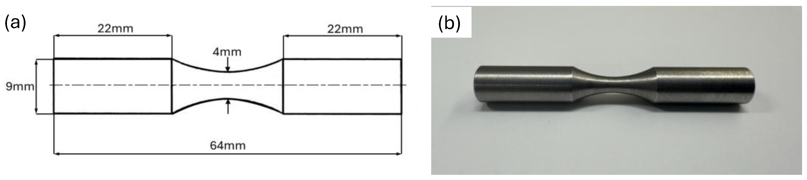
Figure 2.
Experimental setup for nickel electroplating.
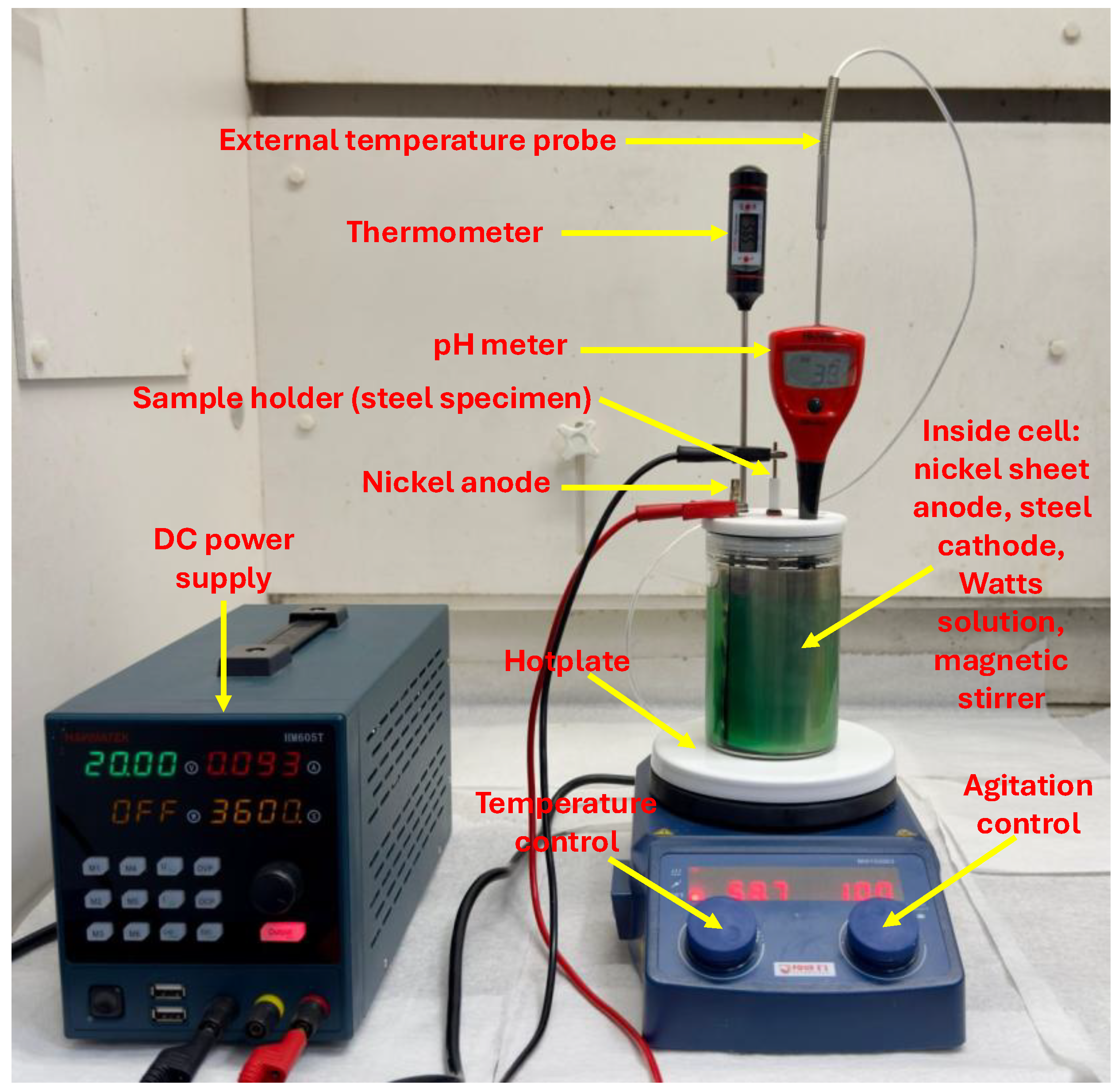
Figure 3.
A nickel-coated fatigue specimen.
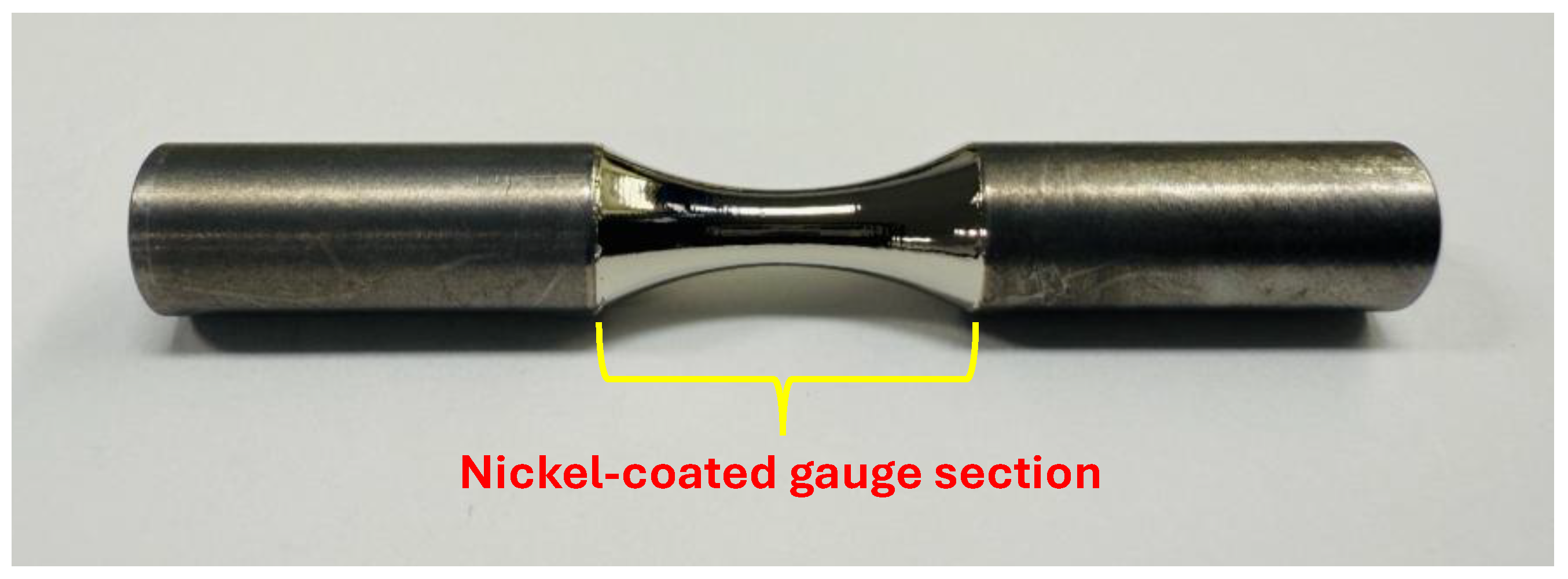
Figure 4.
Experimental setup for electrochemical hydrogen charging.
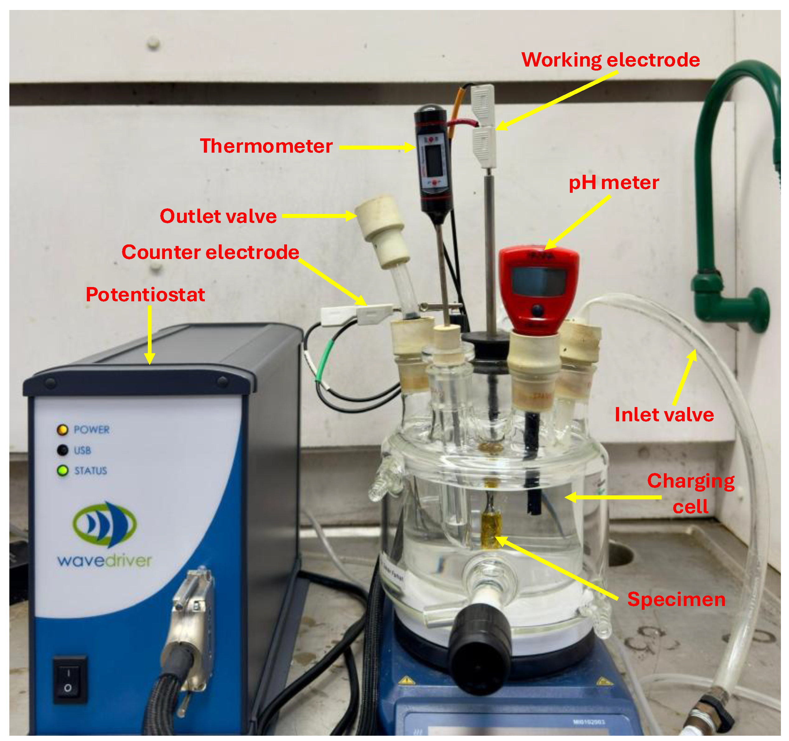
Figure 5.
Experimental setup for fatigue testing.
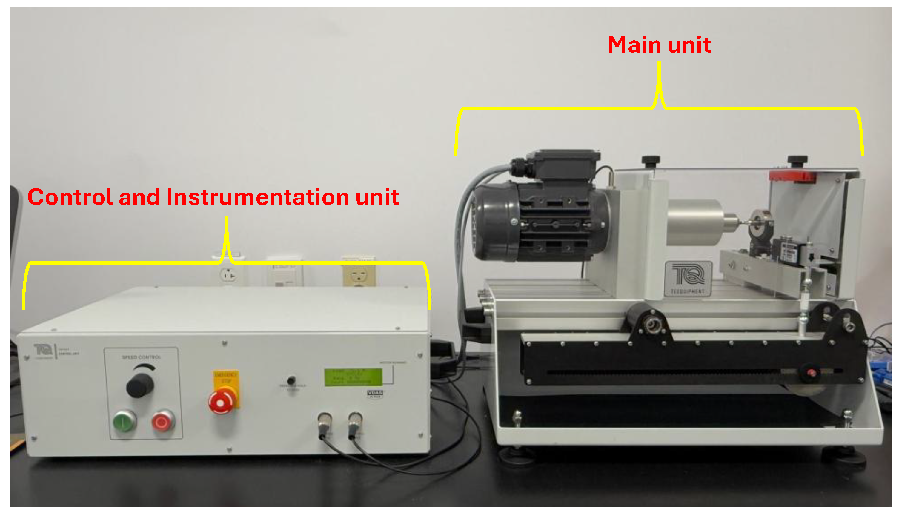
Figure 6.
Main unit of fatigue testing setup: (a) Overview of the major components of the main unit; (b) Close up view of specimen loading position and components.
Figure 6.
Main unit of fatigue testing setup: (a) Overview of the major components of the main unit; (b) Close up view of specimen loading position and components.
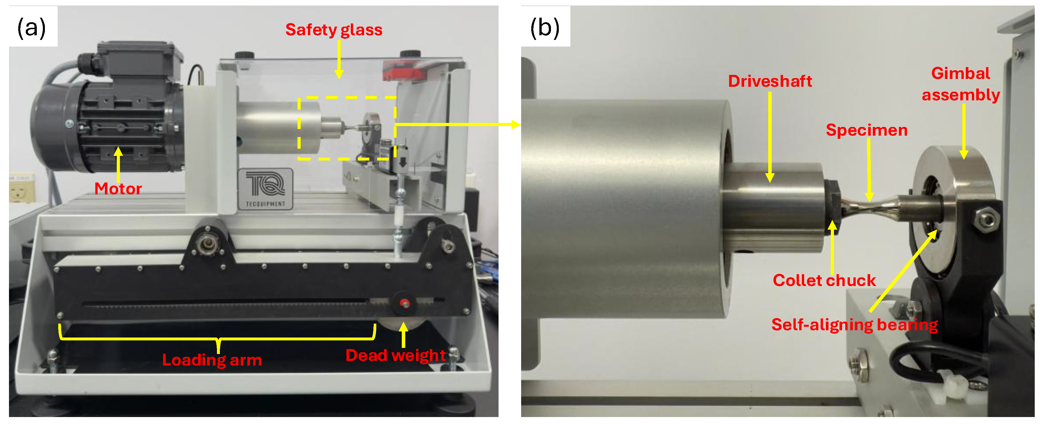
Figure 7.
Graphical representation of rotating cantilever loading of coated specimen.
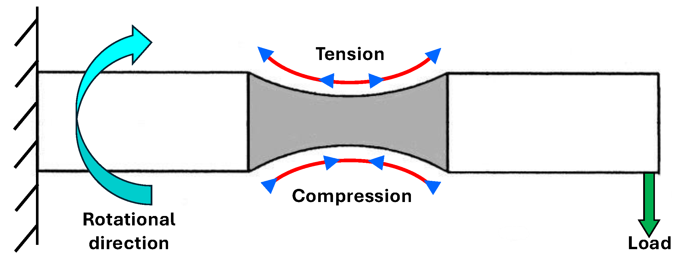
Figure 8.
Schematic illustration of cyclic loading mechanism of coated specimen.
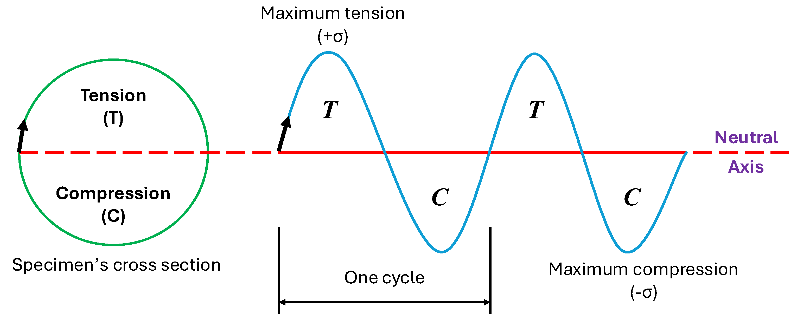
Figure 9.
Control and instrumentation unit: (a) components of the control and instrumentation unit; (b) magnified view of the display unit.
Figure 9.
Control and instrumentation unit: (a) components of the control and instrumentation unit; (b) magnified view of the display unit.
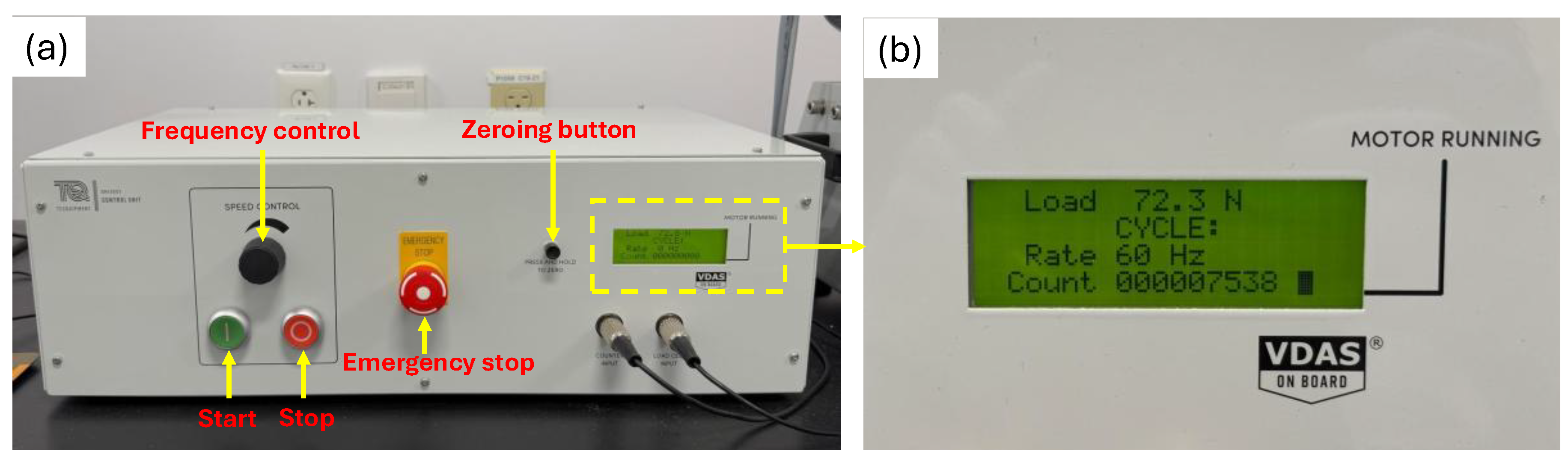
Figure 10.
X-ray diffraction pattern of nickel-coated specimen.
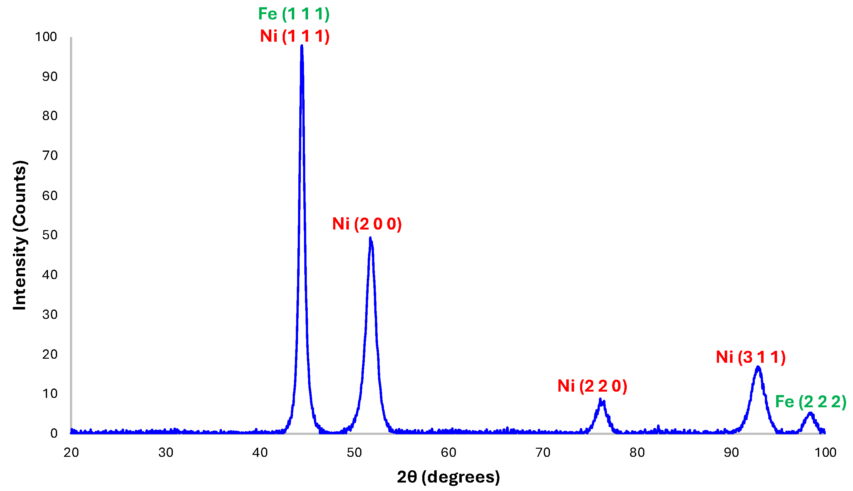
Figure 11.
SEM of microstructural features of the cold-finished mild steel.
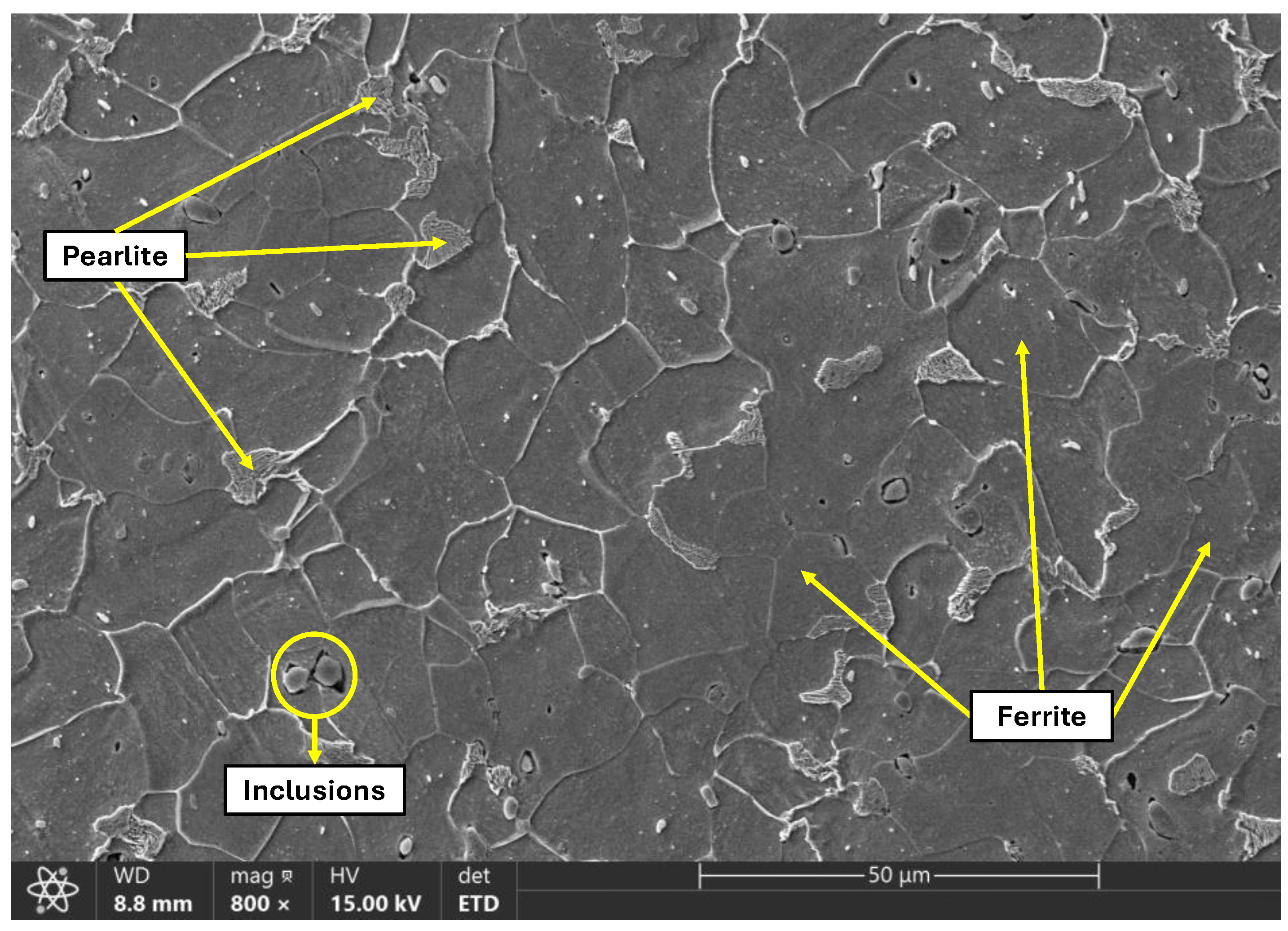
Figure 12.
EDX analysis of the observed steel matrix.
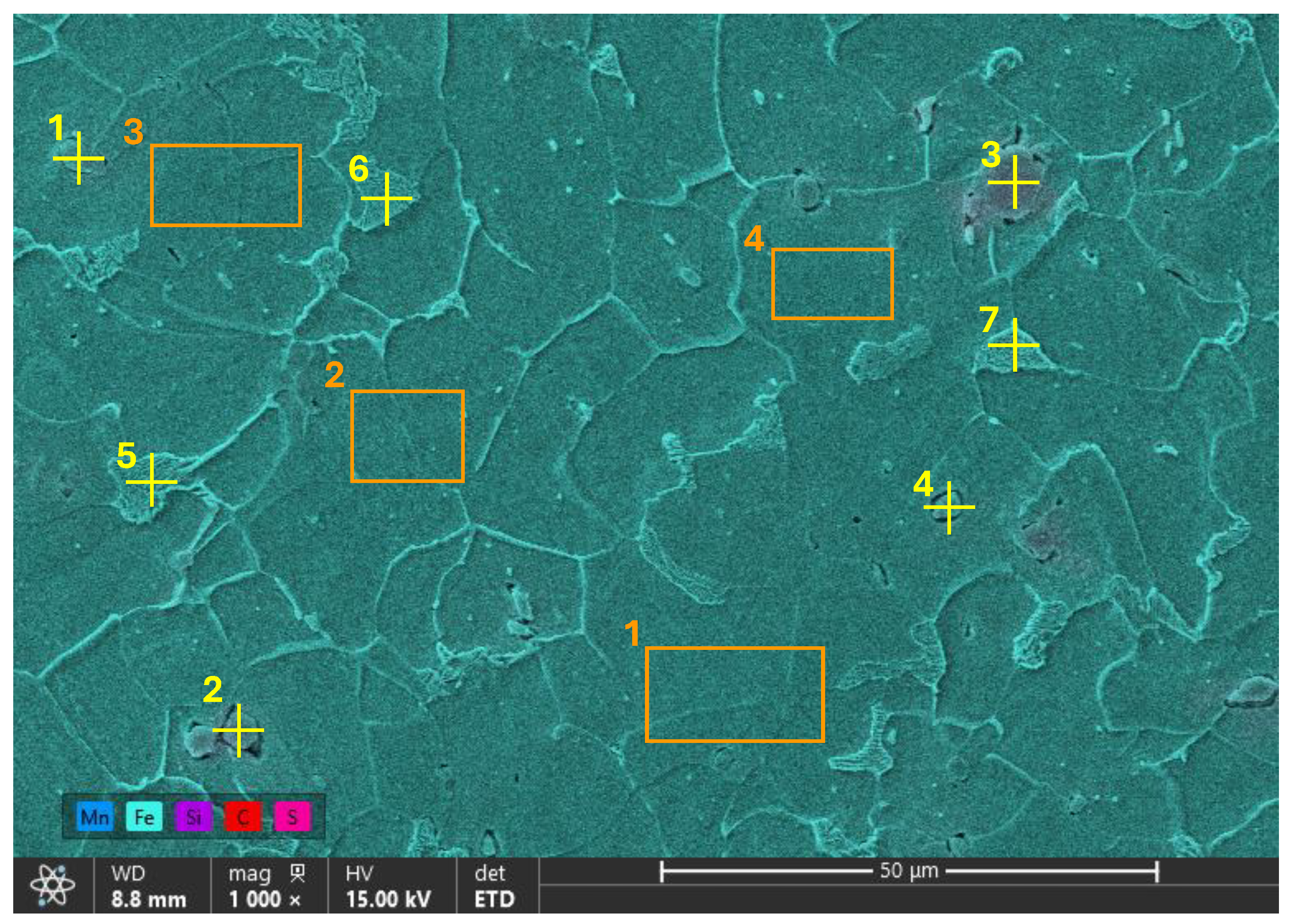
Figure 13.
SEM images of the nickel-coated cross-section of the specimen: (a) coating morphology; (b) EDX mapping of coating cross-section. .
Figure 13.
SEM images of the nickel-coated cross-section of the specimen: (a) coating morphology; (b) EDX mapping of coating cross-section. .
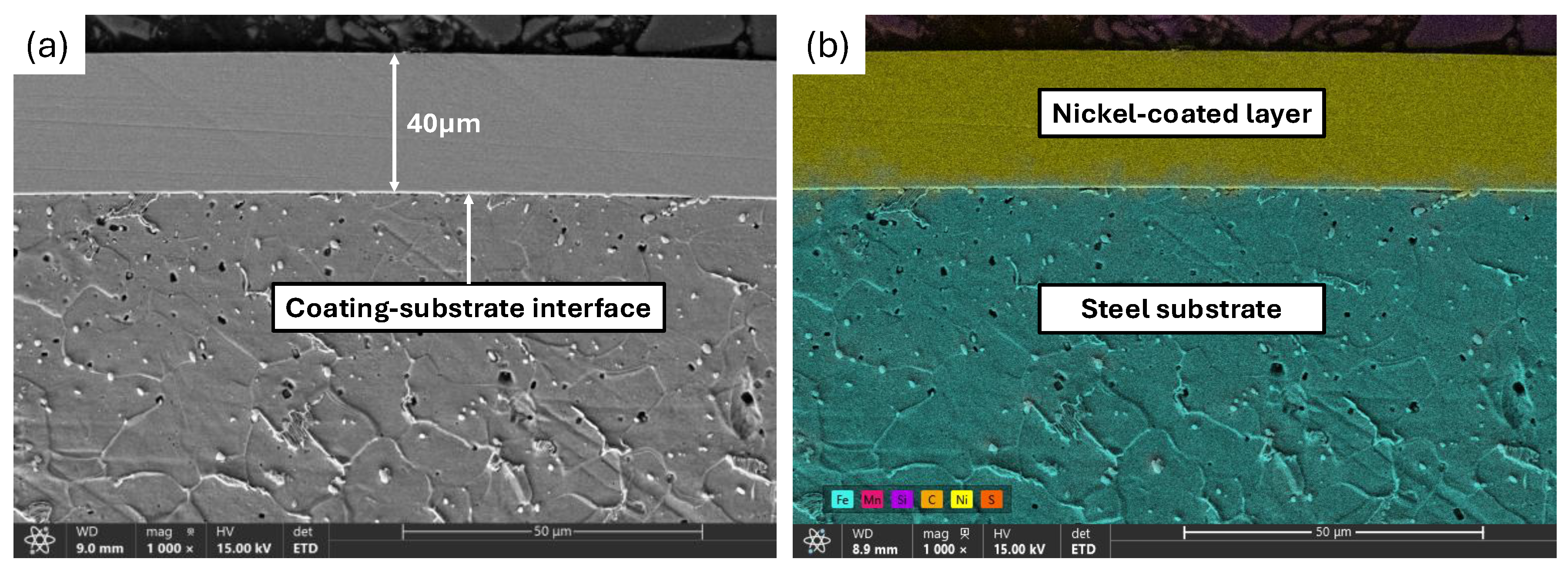
Figure 14.
EDX mapping of elemental constituents of the sample cross-section: (a) nickel; (b) carbon; (c) silicon; (d) iron; (e) sulfur; (f) manganese.
Figure 14.
EDX mapping of elemental constituents of the sample cross-section: (a) nickel; (b) carbon; (c) silicon; (d) iron; (e) sulfur; (f) manganese.
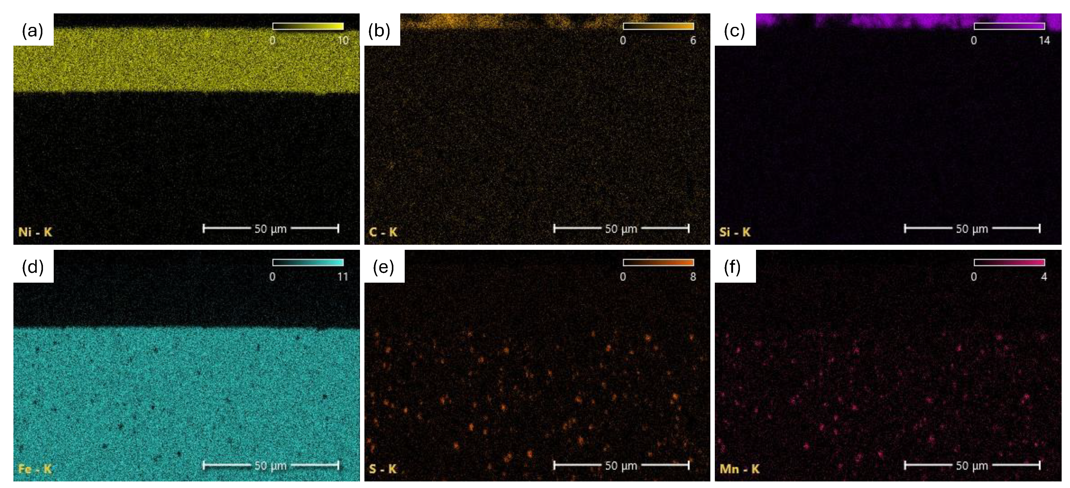
Figure 15.
Results of fatigue tests showing plot for number of cycles to failure/time to failure vs. charging current density.
Figure 15.
Results of fatigue tests showing plot for number of cycles to failure/time to failure vs. charging current density.
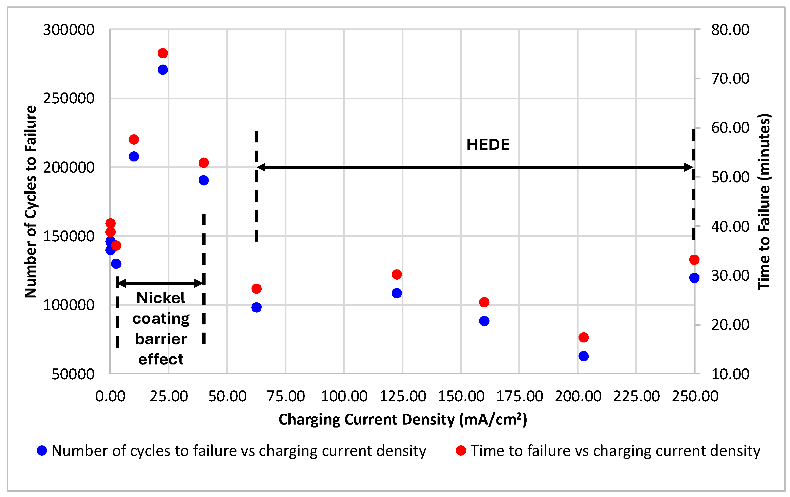
Figure 16.
SEM micrographs of fracture surface of the uncharged coated specimen showing ductile fracture features: (a) Magnified view of the circled area in (b); (b) Low magnified (20×) view of observed fracture surface. (c) Magnified view of dimpled area (500×). (d) Higher magnified view of dimpled area (1200×).
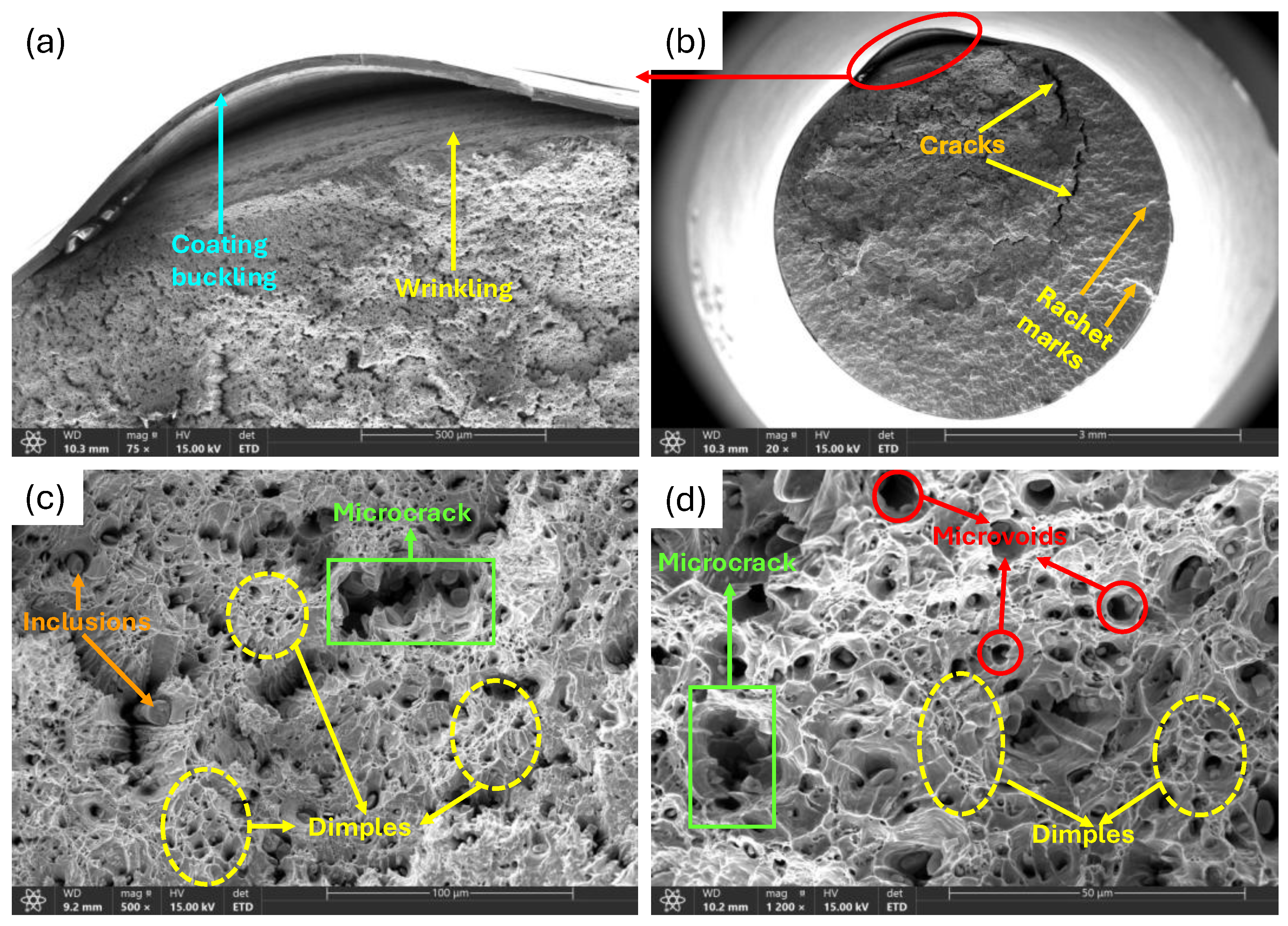
Figure 17.
Fracture surface of a low and moderately charged specimen: (a) 2.49mA/cm2 charged specimen at low magnification (21×); (b) Magnified view of ductile overload zone in (a) (500×); (c) Magnified view of highlighted blue area in (a) (1000×); (d) 22.49mA/cm2 charged specimen at low magnification (21×); (e) Magnified view of stable zone in (d) (150×); (f) Magnified view of highlighted blue area in (d) (800×).
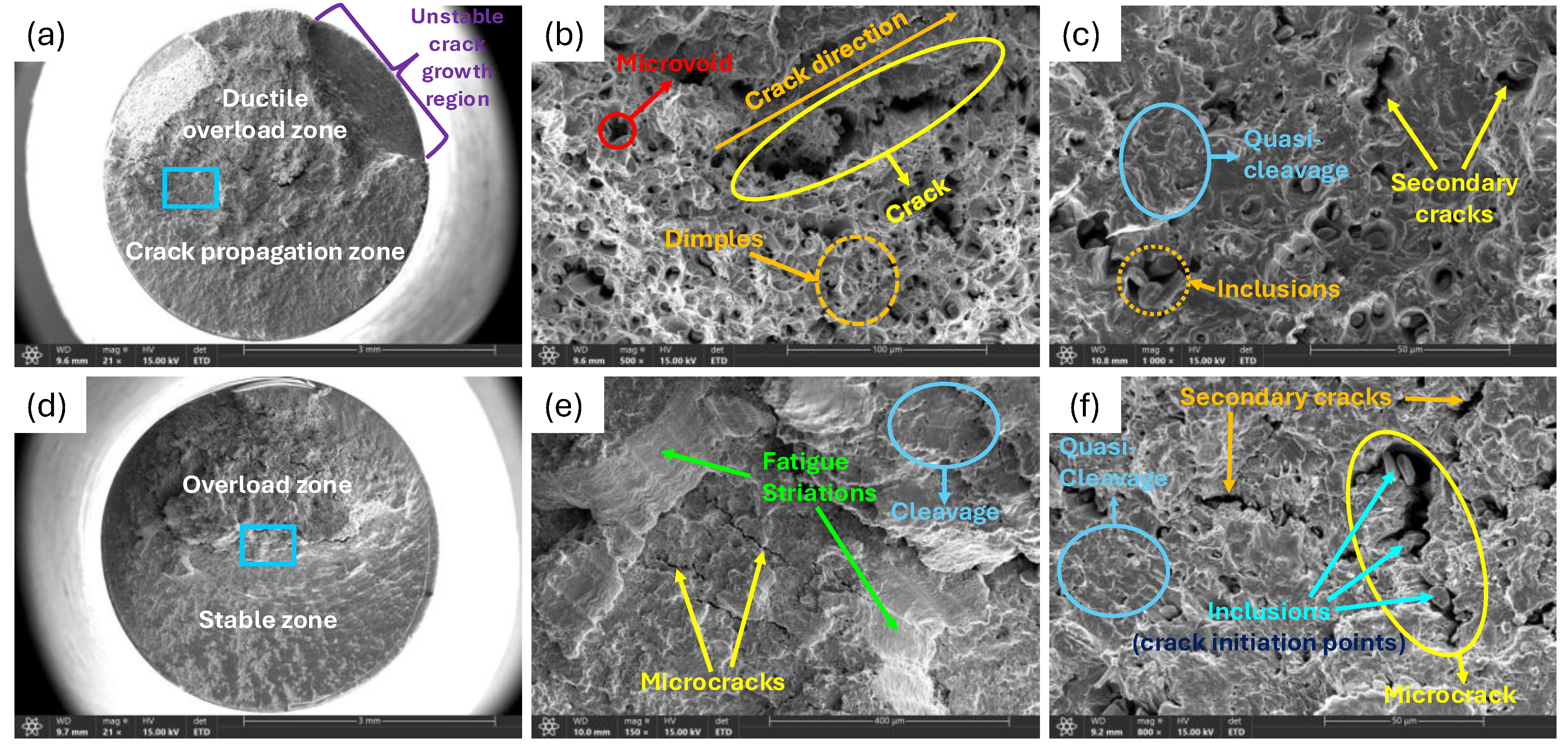
Figure 18.
EDX analysis of observed inclusion phases for moderately charged specimen.
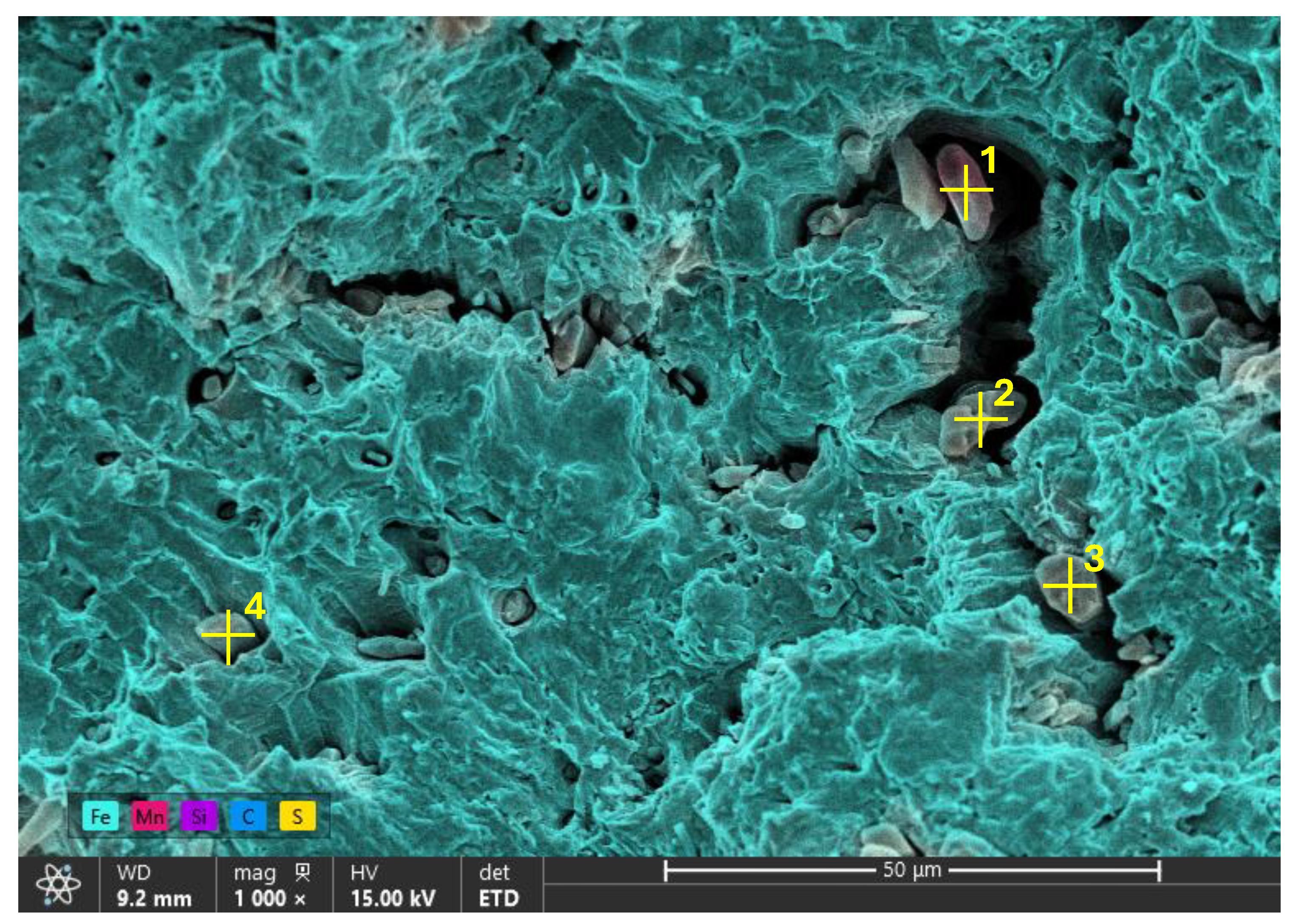

Table 1.
Chemical composition results from ICP analysis
| Element | Fe | C | S | Si | Mn | Cr | Cu | Ni |
| Composition (wt%) | 98.14 | 0.14 | 0.004 | 0.25 | 0.47 | 0.07 | 0.08 | 0.04 |
Table 2.
Selected electrochemical hydrogen charging conditions.
| Current Density (mA/cm2) | 0.00 | 0.16 | 2.49 | 9.99 | 22.49 | 39.99 | 62.48 | 122.47 | 159.96 | 202.45 | 249.93 |
Table 3.
Weight % summary of point analysis on inclusions observed on the specimen’s surface.
| Weight % | ||||
| Element | Point 1 | Point 2 | Point 3 | Point 4 |
| C | 12.8 | 18.8 | 19.7 | 12.8 |
| Si | 0.3 | 0.3 | 0.2 | 0.2 |
| S | 28.5 | 26.8 | 26.8 | 28.1 |
| Mn | 52.8 | 49.2 | 49.9 | 52.7 |
| Fe | 5.6 | 4.9 | 3.4 | 6.2 |
Table 4.
Summary of weight % of the steel matrix.
| Weight % | |||||||
| Element | Point 5 | Point 6 | Point 7 | Region 1 | Region 2 | Region 3 | Region 4 |
| C | 8.0 | 8.5 | 13.4 | 5.9 | 6.3 | 6.4 | 6.2 |
| Si | 0.2 | 0.2 | 0.3 | 0.1 | 0.1 | 0.2 | 0.2 |
| S | 0.0 | 0.0 | 0.1 | 0.0 | 0.1 | 0.1 | 0.1 |
| Mn | 1.3 | 1.2 | 1.6 | 1.2 | 0.7 | 1.1 | 1.5 |
| Fe | 90.5 | 90.1 | 84.6 | 92.8 | 92.8 | 92.2 | 92.0 |
Table 5.
Weight % summary of elemental composition of inclusions phases for a moderately charged specimen.
Table 5.
Weight % summary of elemental composition of inclusions phases for a moderately charged specimen.
| Weight % | ||||
| Element | Point 1 | Point 2 | Point 3 | Point 4 |
| C | 1.9 | 9.8 | 3.5 | 3.0 |
| Si | 0.1 | 0.2 | 0.2 | 0.1 |
| S | 3.2 | 26.8 | 21.7 | 14.6 |
| Mn | 72.0 | 52.1 | 48.6 | 61.9 |
| Fe | 22.8 | 11.1 | 26.0 | 20.4 |
Disclaimer/Publisher’s Note: The statements, opinions and data contained in all publications are solely those of the individual author(s) and contributor(s) and not of MDPI and/or the editor(s). MDPI and/or the editor(s) disclaim responsibility for any injury to people or property resulting from any ideas, methods, instructions or products referred to in the content. |
© 2026 by the authors. Licensee MDPI, Basel, Switzerland. This article is an open access article distributed under the terms and conditions of the Creative Commons Attribution (CC BY) license (http://creativecommons.org/licenses/by/4.0/).
Copyright: This open access article is published under a Creative Commons CC BY 4.0 license, which permit the free download, distribution, and reuse, provided that the author and preprint are cited in any reuse.


