Submitted:
30 January 2026
Posted:
02 February 2026
You are already at the latest version
Abstract
Softening behavior in the heat-affected zone (HAZ) of two X80 pipeline girth welds with different base metal microstructure, i.e. acicular ferrite (AF) dominated (X80-AF) and granular bainite (GB) dominated (X80-GB), were investigated in the present study. Hardness tests, transmission electron microscope (TEM), and electron backscattered diffraction (EBSD) were employed to analyze the softening behavior and corresponding microstructural evolution in the HAZ. The results indicated that softening in the HAZ of two girth welds primarily occurred in the fine-grained (FG) HAZ, while hardening was found in the coarse-grained (CG) HAZ. Due to its high dislocation density and refined interlocking structure, AF could effectively inhibit phase transformation and grain growth during reheating which resulted in smaller grains and lower softening rate in the FGHAZ. In contrast, coarse GB in the base metal was more prone to grain coarsening and hence engendered more pronounced softening. Therefore, for the microstructural design of high strength pipeline steels, increasing the proportion of refined AF is beneficial to the softening resistance and thereby elevates the service safety of pipelines.
Keywords:
softening
; X80 pipeline steel
; girth weld
; heat-affected zone
; base metal microstructure
1. Introduction
With the continuous growth of global energy demand, the scale and technology of oil and gas pipeline construction are developing rapidly [1,2]. As the most economical and efficient method for transporting oil and gas resources, long-term operation safety and reliability of pipeline transportation are of paramount importance [3,4,5]. X80-grade high-strength, high-toughness pipeline steel, renowned for its superior mechanical properties and excellent weldability, has been extensively adopted in various long-distance pipeline projects [6,7]. However, as the strength of high-grade pipeline steel significantly increases, softening in the weld heat-affected zone (HAZ) has become increasingly prominent, emerging as a critical issue that constrains the overall performance and service safety of pipelines.
Basically, softening in the HAZ stems from the alteration of the base material’s original microstructure induced by welding thermal cycles. Microstructure formed during controlled rolling and subsequent cooling, which provide significant dislocation and/or precipitation strengthening effects, undergo recovery, recrystallization, and phase transformation under different welding thermal histories, which weakens or even eliminates these strengthening mechanisms [8,9,10]. Particularly when peak temperatures fall within the intercritical range (e.g., 800 °C to 1000 °C) or the fine-grained range (e.g., 1000 °C to 1200 °C), the original fine, uniform microstructure may partially or fully transform into soft ferrite phase which engenders loss of strengthening effects. This results in a significant reduction in hardness within this region, which is named as the softening zone [11,12,13,14,15]. The softening zone not only degrades the mechanical properties of the HAZ but also may engender a stress concentration zone, compromising the pipeline’s overall integrity under complex loading conditions such as internal pressure, geological hazards, or third-party impacts during long term service of pipelines [16,17].
Effect of welding heat cycles on the microstructure and properties of the HAZ is complex. Based on peak temperature, the HAZ can be subdivided into coarse-grained (CG) HAZ, fine-grained (FG) HAZ, intercritically reheated (IC) HAZ, and subcritically reheated (SC) HAZ. Currently, there is no consistent standpoint regarding the specific location where the softening zone appears in the HAZ of high-strength low-alloy steels. Significant variations in softening zones observed within weld joint of similar steel grades have been reported, and the softening zones are primarily associated to the CGHAZ, FGHAZ, and ICHAZ. These discrepancies are believed to be closely related to the original microstructure of base metal. On one hand, previous research showed that softening predominantly occurs in the CGHAZ. For instance, Jing et al. [18] noted in their study of X70 pipeline steel that the lowest hardness in the HAZ occurred within the CGHAZ. They attributed this to the base metal’s predominant granular bainite (GB) structure, where the uniformly distributed M-A constituents completely dissolved during high-temperature austenitization in the CGHAZ. During cooling, these constituents failed to effectively precipitate again, leading to significant grain coarsening and lack of secondary phase strengthening, thereby causing severe softening. Similar results were also observed by Zhang et al. [19] in GB-dominated X80 steel welds. The transformation of coarse austenite grains into coarse ferrite and pearlite resulted in substantial strength reduction. In contrast, some other studies indicated that softening zones tend to occur more frequently in FGHAZ or ICHAZ rather than CGHAZ. Zhang et al. [20] found the lowest hardness in the FGHAZ of a Nb-Ti microalloyed X80 steel weld, for which the parent microstructure predominantly consists of acicular ferrite (AF). Hu et al. [21] further confirmed that in optimized X80 steel produced via controlled rolling and controlled cooling, when the base metals predominantly consists of AF, the softening zone shifts significantly toward the FGHAZ, exhibiting markedly lower softening rate compared to GB matrix steels. These divergent findings indicate that the location of the softening zone is not only determined by chemical composition but also dependent on the initial microstructural of base metal, such as GB, AF, and their mixed structures which may exhibit significant differences in microstructural evolution and final mechanical property while undergoing similar cycles. Therefore, investigating the mechanism on how the microstructural characteristics of the base metal influence the softening behavior in the HAZ is crucial for optimizing the welding process of X80 pipeline steel, controlling softening levels, and ensuring the safety and reliability of pipeline projects.
The present study investigated the relationship between base metal microstructure and the softening behavior in the HAZ of X80 pipeline girth welds. Two X80 pipeline steels with GB-dominated and AF-dominated microstructure were used to fabricate the girth weld, and micro-Vickers hardness test was conducted from the base metal to the weld zone. Transmission electron microscopy (TEM) was used to characterize microstructure evolution of the base metal and softening zones. Electron backscattered diffraction (EBSD) was used to analyze grain structure and estimate dislocation density in the base metal and the HAZ.
2. Materials and Methods
2.1. Experimental Materials
Two types of X80 pipeline steel with wall thickness of 18. 4 mm from the same manufacturer and milled through similar rolling processes were selected in the present study. Both materials shared similar base alloy compositions (as shown in Table 1), differing only in microstructure. One steel exhibited a microstructure predominantly composed of AF and minor amounts of GB, designated as X80-AF. The other steel featured a microstructure primarily consisting of GB and minor amount of AF, was designated as X80-GB.
Based on the welding parameters according to the China-Russia Eastern Route welding procedure specification (Table 2), the weld consisted of 6 layers and 8 passes. The root pass was performed using Gas Tungsten Arc Welding (GTAW) with ER70S-G filler wire. The filling and cap passes employed gas-shielded flux-cored arc welding (FCAW-G) using E91T1-K2M wire. Current and heat input were progressively adjusted to ensure good weld bead formation with sufficient penetration and toughness. All passes employed direct current reverse polarity (DCEP) with shielding gas flow stabilized at 20–35 L/min. Figure 1 displayed a macro photograph of the girth weld joint cross-section.
2.2. Experimental Method
The composition of the base metal was measured using an optical emission spectrometer (DM5000), with measurement points shown in Figure 2. To ensure accuracy, four testing positions were selected for each weld joint, and the measured results were averaged.
The girth welds were ground and polished. Micro-Vickers hardness testing was performed after etching the microstructure with a 4% nitric acid-alcohol solution. The test force was 1000g, with a load holding time of 15 seconds. Indentation points were taken starting from 0.5 mm below the surface, arranged in 30 rows of 68 points and 30 rows of 68 points, with 0.3 mm spacing between rows and 0.3 mm spacing between adjacent hardness points. The measurement area covered the weld, HAZ, and base metal, as illustrated in Figure 3.
Microstructures were observed using a JSM-7200F scanning electron microscope (SEM). Specimens were sequentially ground with sandpaper, followed by mechanical polishing, and finally etched in a 4% nitric acid–alcohol solution for 15–20 seconds. Further microstructure characterization was performed using transmission electron microscope (TEM, TALOS-F200X) using thin films. First, the sample was mechanically thinned to 80 μm thickness using a Gatan 695 precision microtome. Subsequently, double-sided ion beam polishing was performed with a Gatan PIPS II 695 argon ion polisher at an incidence angle of 4° and an acceleration voltage of 5 kV, ultimately yielding an electron-transparent region <100 nm thick. TEM images were acquired at an acceleration voltage of 200 kV.
Additionally, to obtain crystallographic information such as grain boundaries and grain orientation, electron backscattered diffraction (EBSD) technology was used. The EBSD specimen was ground with 5000-grit sandpaper, followed by mechanical polishing using diamond polishing compounds of 2.5 μm, 1.5 μm, and 0.5 μm grit sizes. It was then electrolytically polished in 10% perchloric acid ethanol solution at 30 V for approximately 16 seconds. EBSD testing was conducted at an operating voltage of 20 kV and a current of 108.4 μA. The scanning step size ranged from 0.08 to 0.15 μm, determined by the test location and purpose. Following testing, data extraction and analysis were performed using HKL CHANNEL5 software.
3. Results and Discussion
3.1. Hardness Distribution of Girth Weld Joints
The hardness contour maps of the two girth welds are shown in Figure 4. The blue and purple regions in Figure 4(a-b) are corresponded to softening zones. Figure 4(c) shows the hardness variation curves along horizontal lines passing through the lowest hardness points, as indicated in Figure 4(a-b). From the hardness contour maps, the hardness of the base metal was determined by averaging the measured values in the region unaffected by welding thermal cycles. The lowest hardness point in the HAZ is selected as the minimum hardness of the HAZ. Calculations reveal that X80-AF base metal has the average hardness of 224.1 HV1 and minimum HAZ hardness of 216.4 HV1, with softening rate of 3.44%. In contrast, X80-GB base metal has average hardness of 200.6 HV1 and minimum HAZ hardness of 175.6 HV1, with a softening rate of 12.46%. The hardness distribution curve of both samples were consistent, with softening zones localized in the FGHAZ and hardened zones primarily appeared in the CGHAZ. X80-AF weld joint showed higher overall hardness level, with both softened and hardened zones exhibiting higher specific hardness values than that of X80-GB. Meanwhile, the softening zone of X80-AF showed a smaller hardness reduction and more restricted distribution, while the HAZ of X80-GB exhibited pronounced softening, significant hardness fluctuations, and a broader softening zone.
3.2. Base Metal Microstructure Analysis
The base metal microstructure of the two X80 steels are shown in Figure 5(a-b). Both steels exhibit AF and GB mixed microstructure, but with different fractions: X80-AF predominantly consists of AF with small fraction of GB, while X80-GB is dominated by GB. All-Euler map and IPF diagrams for the base metals are shown in Figure 5(c-f), with effective grain sizes (equivalent circle diameters) listed in Table 3. The average grain size for X80-AF and X80-GB specimens are 4.31 μm and 5.15 μm, respectively. The average grain size of X80-GB is larger than that of X80-AF, with larger maximum grains as well. AF grains exhibit elongated needle-like or lamellar shapes. These needle-like grains intercross with each other from different orientations, forming an interlocking three-dimensional structure. This structure results in tortuous and complex grain boundaries, significantly increasing the resistance to grain boundary migration. The growth of a single grain would be mechanically impeded by multiple surrounding needle-shaped grains with different orientations, effectively “locking” it within the structure. Consequently, the AF microstructure inherently has the ability to inhibit grain growth. TEM images of the two base materials are shown in Figure 6. The X80-AF structure exhibits a needle-like structure with fine grains and high density of dislocations. Microstructure of X80-GB generally appears more uniform, with relatively larger grains predominantly in a blocky structure, though fine grains and some lamellar structures are also visible.
3.3. Microstructural Analysis of the Softening Zone
Figure 7 presents all-Euler and IPF maps of the FGHAZ in the two X80 girth welds. Combined with the data presented in Table 4, the average effective grain size in the FGHAZ of X80-AF is 3.72 μm, smaller than 4.92 μm in the FGHAZ of X80-GB. This difference is directly correlated to their varied degrees of softening. The microstructure of the X80-AF softening zone consists of PF and AF. The PF phase exhibits regular equiaxed grains with straight boundaries, while the AF phase retains elongated acicular structures with diverse orientations and interlaced arrangements. The overall microstructure exhibits a complex coexistence of regular polygonal regions and irregular needle-like structures. In the X80-GB softening zone, the microstructure is dominated by PF, appearing as large, flat polygonal regions with regular shapes and uniform distribution. AF content is low, with only sparse needle-like structures visible in localized areas. The overall morphology is characterized by predominantly regular polygonal regions, resulting in a relatively simple and uniform microstructure. TEM images of the X80-AF FGHAZ showed fine and interlocked needle-like structures and high-density dislocations (Figure 8a), whereas those of the X80-GB FGHAZ showed relatively uniform equiaxed grains with lower dislocation density (Figure 8b).
3.4. General Discussion on Softening Mechanism
(1) Influence of original base metal microstructure on hardness
Differences in the degree of softening among base metals arise from variations in phase transformation temperatures and thermal stability during welding thermal cycles. Studies by Li [22] and Duan [23], employing thermal expansion analysis, revealed significant differences in volumetric response between AF and GB during heating, which directly influence their high-temperature stability and hardness retention. The AF microstructure is characterized by a high dislocation density and fine, interlaced lamellar structures, with grain boundaries predominantly exhibiting a high-angle misorientation. This effectively impedes atomic diffusion and grain boundary migration, resulting in a low and stable thermal expansion coefficient during heating. Its thermal expansion curve exhibits a gentle slope and weak phase transformation hysteresis, indicating excellent stability under thermal disturbance [24]. In contrast, GB typically precipitates along prior austenite grain boundaries, forming continuous or semi-continuous network-like distributions. It features coarse grains, low dislocation density and a more regular microstructural morphology [25]. During the heating stage of welding thermal cycles (especially within the 500–700 °C range), GBs are prone to grain boundary sliding, migration before local melting, and accompanying recovery processes. This results in a significantly increased slope of their thermal expansion curve within this temperature range, reflecting a pronounced tendency toward thermal softening [26]. Furthermore, coarse morphology of GB lacks effective dislocation strengthening mechanisms, making it more susceptible to grain coalescence and microstructural coarsening under thermal loading. Consequently, after undergoing identical welding heat cycles, X80 pipeline steel with an AF-dominated microstructure exhibits minimal hardness loss due to its high thermal stability. Conversely, regions containing a higher proportion of GB experience significant softening due to grain boundary weakening, microstructural coarsening, and reduced dislocation density. This demonstrates that AF, as the ideal primary structure for X80 steel, could more effectively resist heat-induced softening in the weld HAZ, thereby better preserving the overall mechanical properties of the joint region.
(2) Effect of Dislocation Density on Hardness
Kernel Average Misorientation (KAM) maps are widely employed to assess local strain distributions under various conditions, as they correlate with the geometrically necessary dislocation density (GND density). The EBSD KAM maps of the two girth weld joints covering the region from base metal to the HAZ and weld metal are presented in Figure 9. As shown in Figure 9, in the case where the base metal consists of AF, the high dislocation density was observed through KAM map, either in the BM or the HAZ regions (i.e., CFHAZ, FGHAZ and ICHAZ) which could effectively suppresses grain growth during welding thermal cycles, thereby minimizing post-weld softening. In contrast, when the base metal is composed of GB, dislocation density is notably lower than that in X80-AF, which provides insufficient resistance to grain growth in the FGHAZ. Consequently, grain coarsening occurs in the FGHAZ after welding, resulting in a significant reduction in hardness and more pronounced softening in the X80-GB girth weld joint.
As the AF phase proportion increases in pipeline steel base materials, AF-dominant pipeline steels exhibit higher dislocation density. This imposes greater resistance to grain boundary migration, thereby restricting grain boundary mobility and effectively suppressing grain growth in the weld HAZ. Consequently, such microstructures exhibit pronounced resistance to softening, accompanied by lower softening rates. Conversely, GB-dominated microstructure exhibit a lower dislocation density, which facilitates grain coarsening during welding thermal cycles. This leads to elevated softening rates in the post-weld condition.
In summary, under identical welding conditions (heat input) and similar chemical composition, the increase in AF fraction, along with reduction in average grain size and higher dislocation density in the base metal together enhances the resistance to softening during welding. Therefore, AF-dominated microstructure design is preferred from the point of view of softening resistance.
4. Conclusions
- For the two girth weld joints with different base metal microstructure, similar chemical composition and identical welding parameters, softening is likewise observed in the FGHAZ. AF-dominated microstructure exhibits superior resistance to softening, while GB-dominated steel exhibit notably higher softening rates in the FGHAZ.
- Higher softening rates for GB-dominated pipeline steel is due to larger fraction of coarser PF in the FGHAZ, while more AF in smaller size is obtained in the FGHAZ of AF-dominated pipeline steel which is attributed to their higher dislocation density and interlocked structure. During welding, AF is less susceptible to transform into GB or PF and hence undergoes less pronounced grain coarsening.
- The anti-softening mechanism for AF-dominated steel is attributed to its higher dislocation density and smaller grain size which engenders higher thermal stability than that of GB-dominated steel. For the anti-softening design, AF is a more preferred microstructure.
Abbreviations
The following abbreviations are used in this manuscript:
| AF | Acicular Ferrite |
| CGHAZ | Coarse Grained Heat Affected Zone |
| FGHAZ | Fine Grained Heat Affected Zone |
| GB | Granular Bainite |
| HAZ | Heat Affected Zone |
| ICHAZ | Intercritical Heat Affected Zone |
| PF | Polygonal Ferrite |
| SCHAZ | Subcritical Heat Affected Zone |
References
- Yan, L.; Zhao, Y.; Sun, P.; Liu, M.; Wang, Q. The distribution status and development trend of global oil & gas pipelines. Oil & Gas Storage and Transportation 2017, 36, 481–486. [Google Scholar]
- Wang, G.; Cheng, Q.; Zhao, W.; Liao, Q.; Zhang, H. Review on the transport capacity management of oil and gas pipeline network: Challenges and opportunities of future pipeline transport. Energy Strategy Reviews 2022, 43, 100933. [Google Scholar] [CrossRef]
- Xu, B.; Duan, L.; Xue, X.; Lan, H.; Chen, K. Research on Connection and Function Reliability of the Oil&Gas Pipeline System. MATEC Web of Conferences 2017, 139, 00116. [Google Scholar] [CrossRef]
- Fan, Y.; Feng, X. Research on integrity Management of long distance pipeline. E3S Web of Conferences 2023, 385, 03011. [Google Scholar] [CrossRef]
- Alamri, A. H. Localized corrosion and mitigation approach of steel materials used in oil and gas pipelines – An overview. Engineering Failure Analysis 2020, 116, 104735. [Google Scholar] [CrossRef]
- Zhang, W.; Li, H.; Chi, Q.; Zhao, X.; Huo, C.; Qi, L.; Li, Y.; Yang, K. Technical specifications for X80 OD 1422 mm line pipes and corresponding products. Natural Gas Industry B 2016, 3, 485–492. [Google Scholar] [CrossRef]
- Li, F. P.; Zhang, Z. W.; Zhang, B. Application Feasibility Study of High Strength Pipeline Steel to Rig Derrick and Substructure. Materials Science Forum 2020, 993, 616–621. [Google Scholar] [CrossRef]
- Kashiwar, A.; Arseenko, M.; Simar, A.; Idrissi, H. On the role of microstructural defects on precipitation, damage, and healing behavior in a novel Al-0. 5Mg2Si alloy. Materials & Design 2024, 239, 112765. [Google Scholar]
- Song, K.; Wang, K.; Zhao, L.; Xu, L.; Ma, N.; Han, Y.; Hao, K.; Zhang, L.; Gao, Y. A physically-based constitutive model for a novel heat resistant martensitic steel under different cyclic loading modes: Microstructural strengthening mechanisms. International Journal of Plasticity 2023, 165, 103611. [Google Scholar] [CrossRef]
- Lomozik, M. A study of structural changes in construction steels under the conditions of welding thermal cycles in the new measurement station at the Welding Institute. Welding International 2013, 28(12), 941–946. [Google Scholar] [CrossRef]
- Zong, Y.; Liu, C. M. Microstructure and Properties of HAZ in Low-Carbon Bainite E550 Steel during Double-Pass Welding Thermal Cycle. Materials Science Forum 2018, 913, 317–323. [Google Scholar] [CrossRef]
- Jundong, J.; Qingshuang, M.; Leli, C.; Rui, L.; Huijun, L.; Qiuzhi, G. Mechanism of Interfacial Microstructure Evolution of G115 Steel in Simulated Heat Affected Zone; Cailiao gongcheng: Publisher, 2024. [Google Scholar]
- Hu, L.; Li, X.; Luo, W.; Li, S.; Deng, D. Residual stress and deformation in UHS quenched steel butt-welded joint. International Journal of Mechanical Sciences 2023, 245, 108099. [Google Scholar] [CrossRef]
- Yang, C. G.; Zhen, Q.; Huang, Z. J.; Xu, W. P. Softening Mechanism in Heat Affected Zone of 2519 High Strength Al-Cu Alloy. Materials Science Forum 2013, 749, 387–391. [Google Scholar] [CrossRef]
- Cao, R.; Yang, Z.; Li, J.; Liang, X.; Lei, W.; Zhang, J.; Chen, J. Effect of Peak Temperature on Microstructure and Mechanical Properties of Thermally Simulated Welding Heat-Affected Zones for 09MnNiDR Steel. Journal of Materials Engineering and Performance 2020, 29, 7063–7072. [Google Scholar] [CrossRef]
- Zhang, W.; Fu, X.; Hu, M.; Xu, K.; Dai, K.; Shi, J.; Ji, Y.; Dong, C. Effects of external corrosion defect growth on wall pipeline under internal pressure and various defect sizes with mechano-electrochemical interaction. Materials and Corrosion 2024, 75, 1348–1358. [Google Scholar] [CrossRef]
- Hu, W.; Gong, B.; Chang, Q.; Zhao, Z.; Dai, L.; Liu, Y. Strain fracture behaviors and crack equivalence of X80 welded joints with non-sharp notches at weld root. International Journal of Pressure Vessels and Piping 2025, 214, 105414. [Google Scholar] [CrossRef]
- Jing, N.; Hongyuan, C.; Jia, L.; Ruiliang, J.; Xiaoxia, Z. Study on Softening in HAZ and Its Influence on Welded Joints of X70 Pipeline Steel; Hot Working Technology: Publisher, 2016. [Google Scholar]
- Zhang, T.; Roy, S.; Patra, S.; Poole, W. J.; Militzer, M. Intercritical Austenite Formation and Decomposition in the Coarse Grain Heat-Affected Zone of an X80 Line Pipe Steel. Metallurgical and Materials Transactions A 2022, 53, 3239–3244. [Google Scholar] [CrossRef]
- Jianxun, Z.; Qian, S.; Zongyue, B.; Hui, N. Research on Microstructure and Performance in Welding HAZ of X100 SAWH Pipe; Welded Pipe and Tube: Publisher, 2012. [Google Scholar]
- Hu, M. J.; Wang, P.; Lin, W. P.; Wang, X. Y.; Ji, L. K. SH-CCT of High-Strain Pipeline Steel X80. Advanced Materials Research 2012, 472, 1179–1182. [Google Scholar] [CrossRef]
- Li, B. Research on Transformation Law of X80 Pipeline Steel; Wide and Heavy Plate: Publisher, 2015. [Google Scholar]
- Duan, H. Microstructure Control and Strengthening-Toughening Mechanisms of High-Strength Pipeline Steel for Low-Temperature Service. Ph.D. Dissertation, University of Science and Technology of China, Hefei, China, 2022. [Google Scholar]
- Zhao, H.; Gao, J.; Wu, G.; Wu, H.; Zhang, C.; Huang, Y.; Luo, Y.; Yang, X.; Wang, S. Crystallographic characteristics of acicular ferrite nucleated on inclusions in a HSLA steel. Journal of Materials Research and Technology 2024, 28, 1957–1966. [Google Scholar] [CrossRef]
- Hu, B.; Shi, G.; Wang, Q.; Zhao, L.; Fan, H.; Tang, Y.; Wang, W.; Wang, Q.; Liu, R. Elucidating the heat input on CGHAZ microstructure and its irregular effect on impact toughness for a novel V–N microalloying weathering steel. Journal of Materials Research and Technology 2023, 25, 5888–5906. [Google Scholar] [CrossRef]
- Duan, Q.; Pan, H.; Fu, B.; Yan, J. An Investigation on the Strengthening Mechanism Based on Grain-Boundary Misorientation of High-Strength Pipeline Steel. Steel Research International 2019, 90. [Google Scholar] [CrossRef]
Figure 1.
Macrographs of X80 pipeline steel girth weld joints. (a) X80-AF; (b) X80-GB.
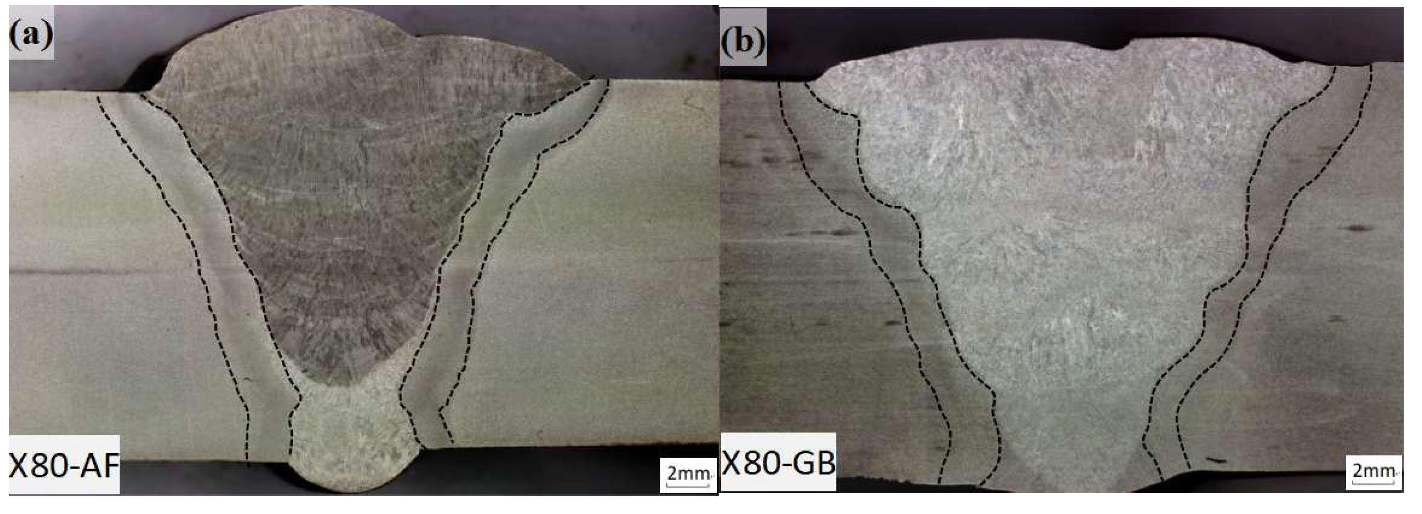
Figure 2.
Composition test locations for X80 pipeline steel girth weld.
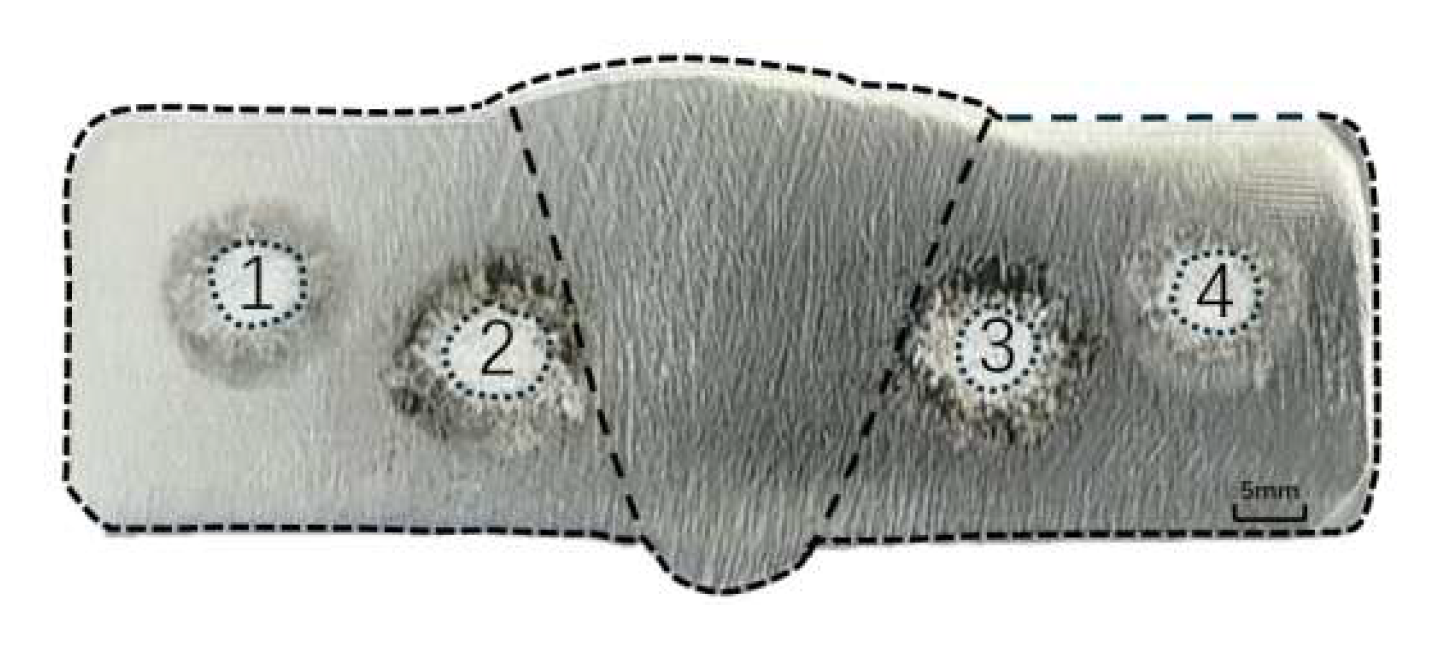
Figure 3.
Schematic of hardness indentation layout for X80 girth weld joints.
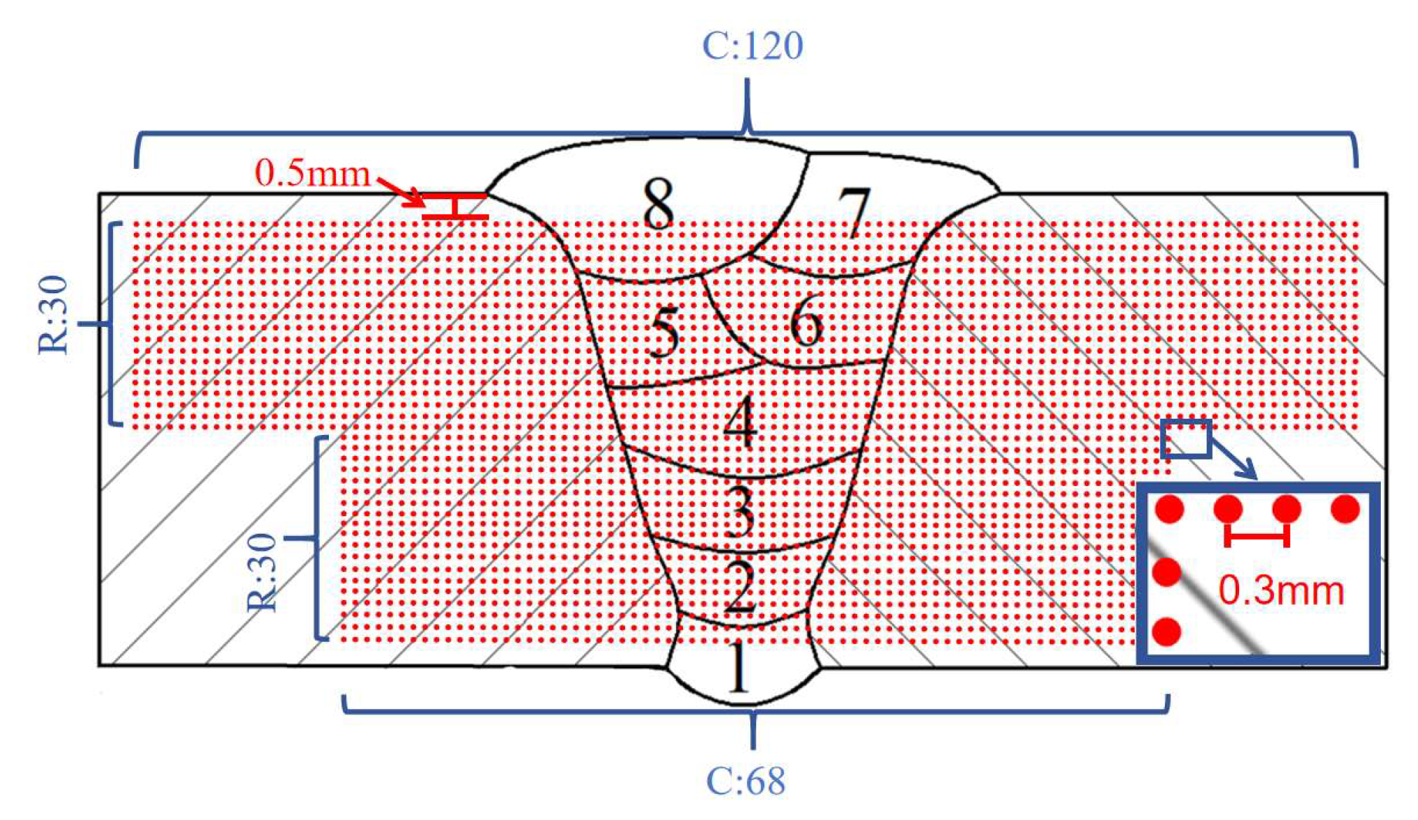
Figure 4.
Hardness test results for girth welds. (a) X80-AF hardness contour map; (b) X80-GB hardness contour map; (c) Hardness variation curves along horizontal lines passing through the lowest hardness points as indicated in (a) and (b).
Figure 4.
Hardness test results for girth welds. (a) X80-AF hardness contour map; (b) X80-GB hardness contour map; (c) Hardness variation curves along horizontal lines passing through the lowest hardness points as indicated in (a) and (b).
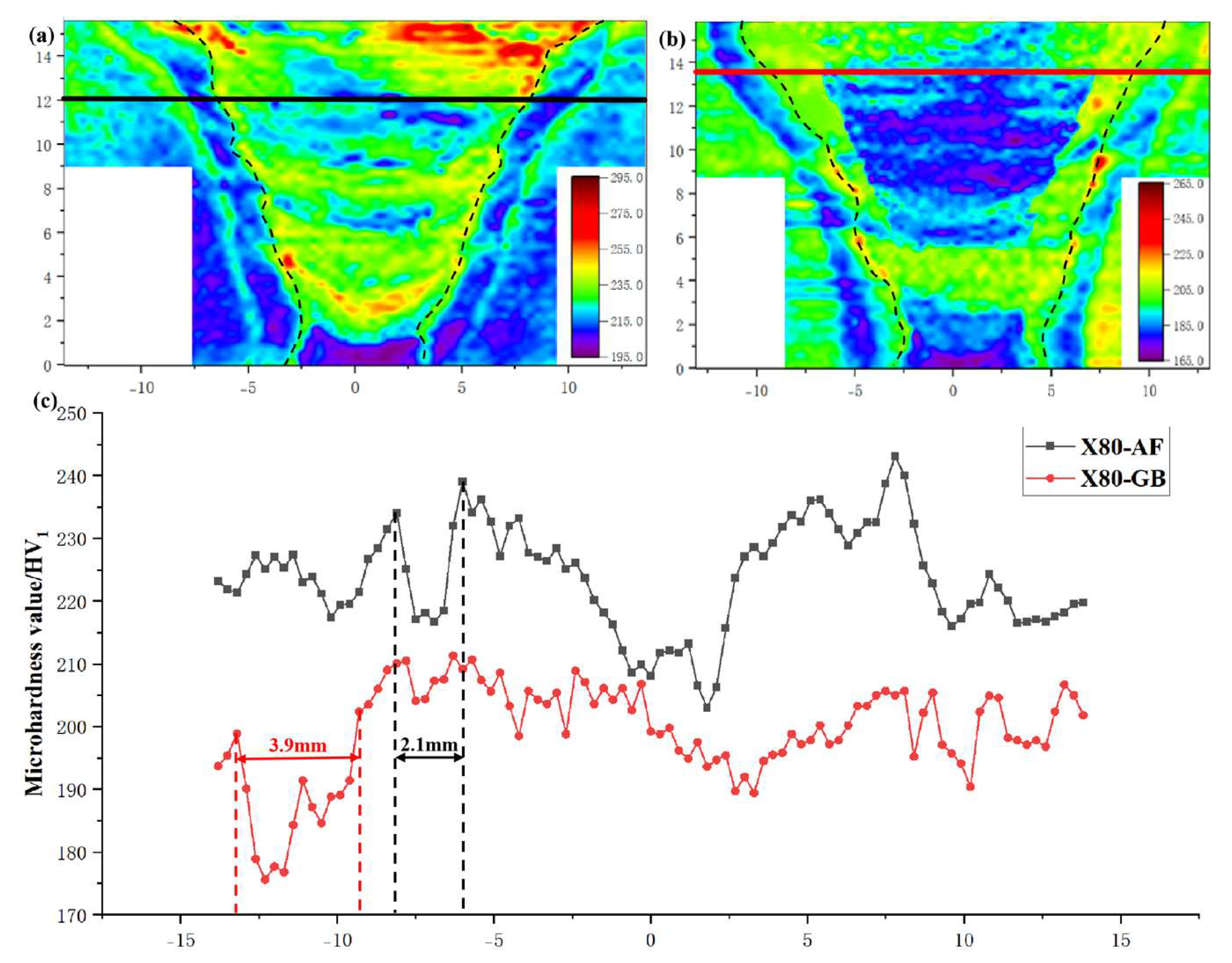
Figure 5.
Metallographs around hardness indentation of base metal (a-b) and corresponding EBSD characterization (c-f). (a) X80-AF base metal; (b) X80-GB base metal; (c) all-Euler map of X80-AF base metal; (d) all-Euler map of X80-GB base metal; (e) IPF map of X80-AF base metal; (f) IPF map of X80-GB base metal.
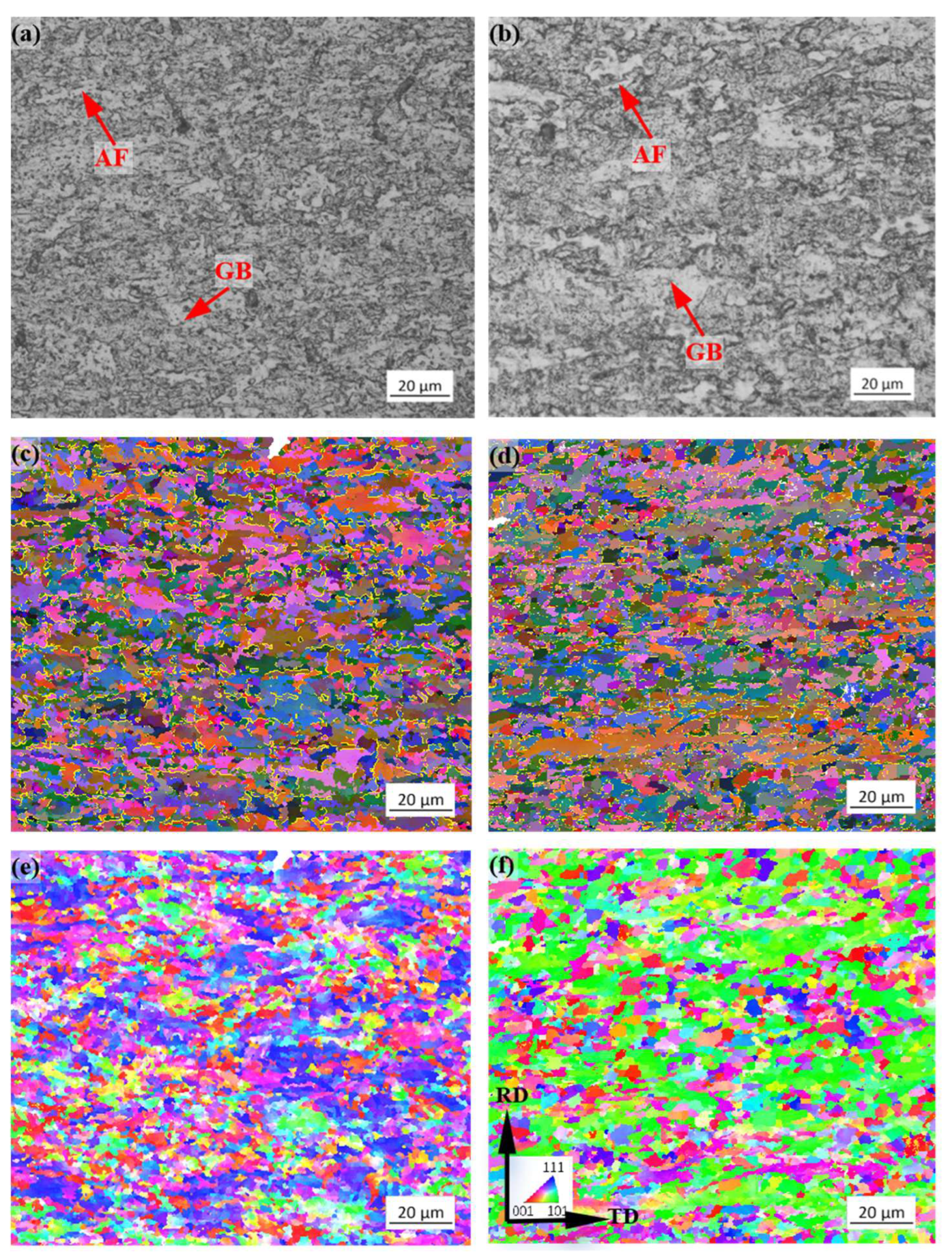
Figure 6.
TEM micrographs of base metal. (a) X80-AF; (b) X80-GB.
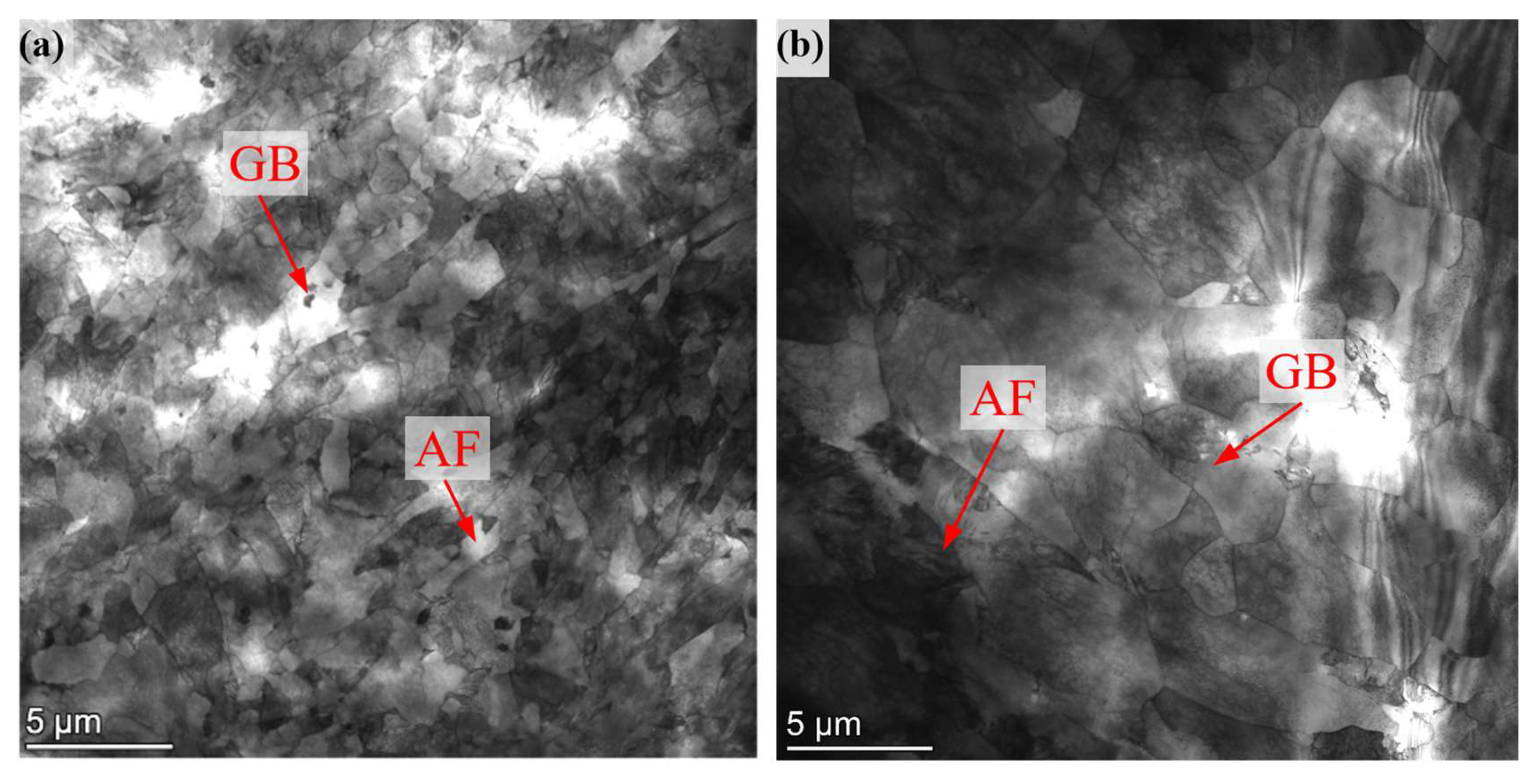
Figure 7.
Metallographs around hardness indentation of FGHAZ (a-b) and corresponding EBSD characterization (c-f). (a) FGHAZ of X80-AF; (b) FGHAZ of X80-G; (c) all-Euler map of X80-AF FGHAZ; (d) all-Euler map of X80-GB FGHAZ; (e) IPF map of X80-AF FGHAZ; (f) IPF map of X80-GB FGHAZ.
Figure 7.
Metallographs around hardness indentation of FGHAZ (a-b) and corresponding EBSD characterization (c-f). (a) FGHAZ of X80-AF; (b) FGHAZ of X80-G; (c) all-Euler map of X80-AF FGHAZ; (d) all-Euler map of X80-GB FGHAZ; (e) IPF map of X80-AF FGHAZ; (f) IPF map of X80-GB FGHAZ.
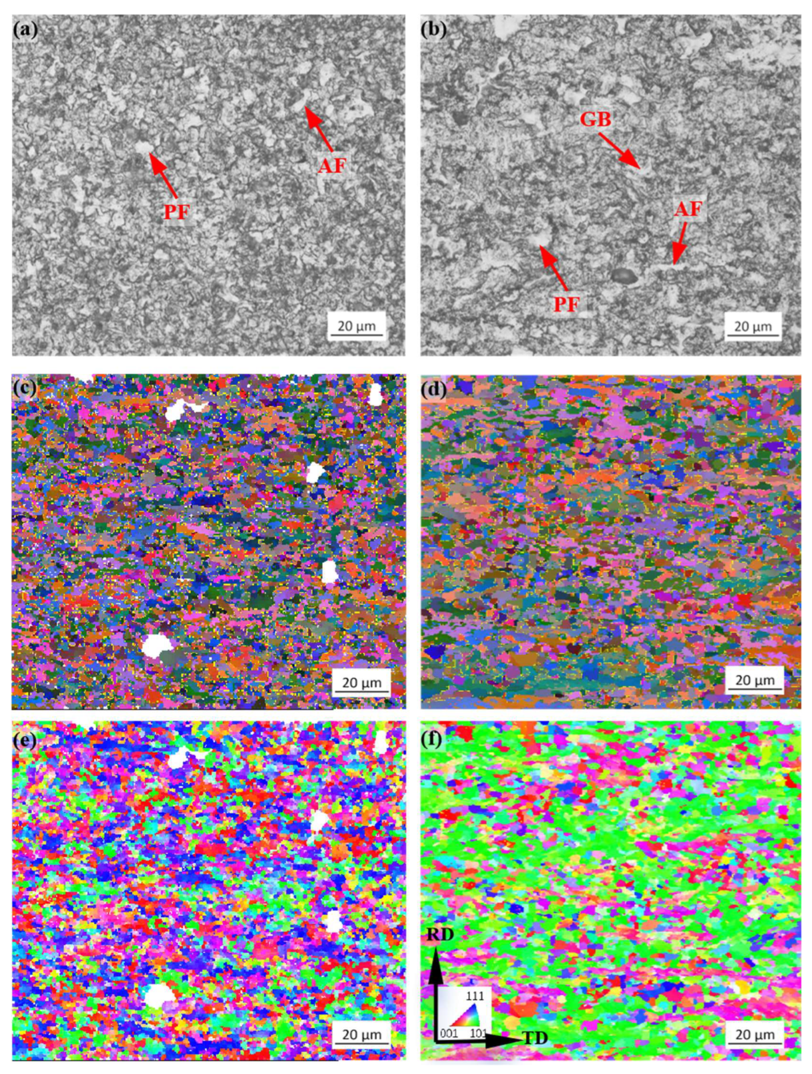
Figure 8.
TEM micrographs of FGHAZ. (a) X80-AF; (b) X80-GB.
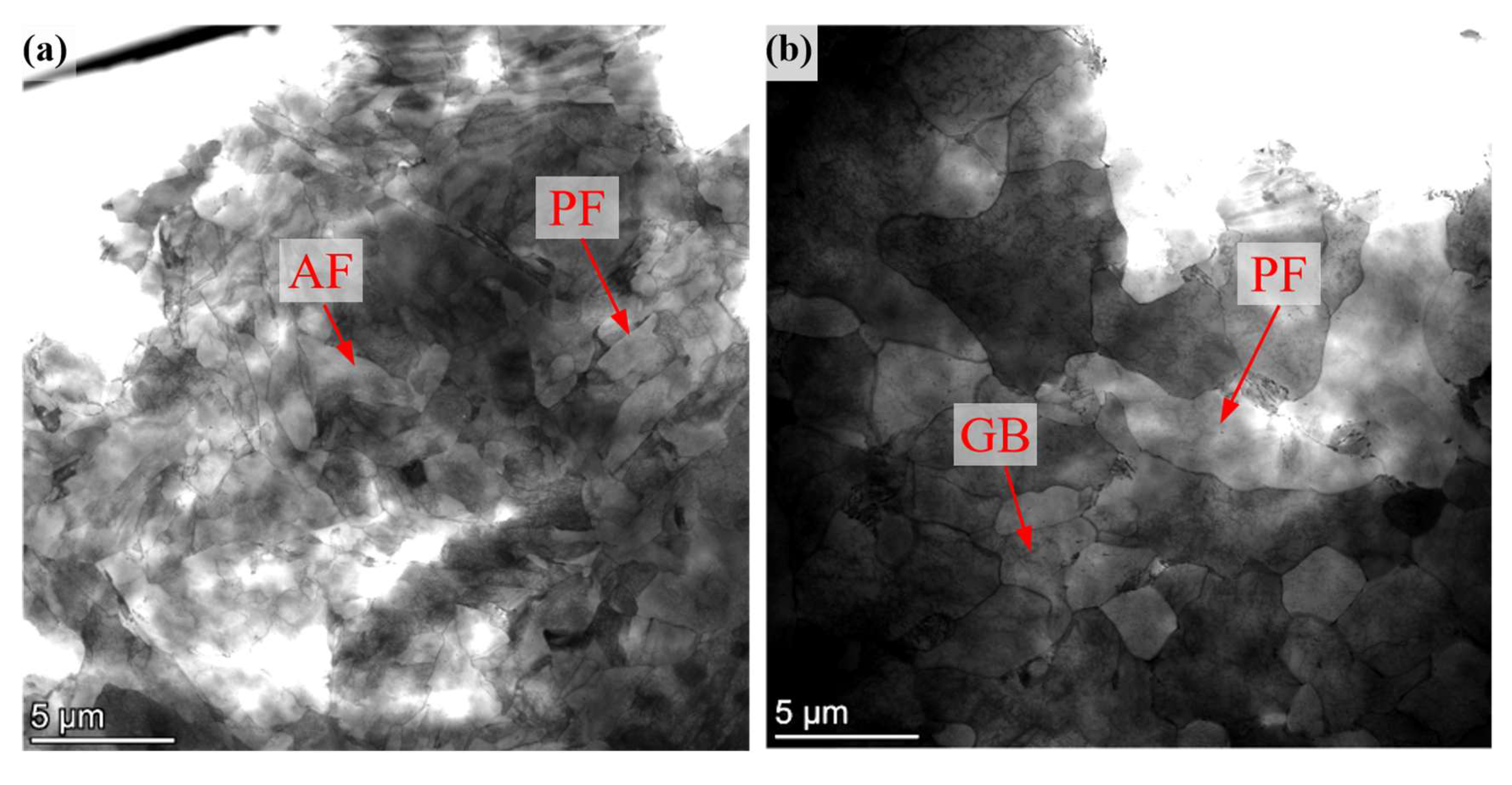
Figure 9.
KAM images of the HAZ and base metal in the ring weld joint. (a) X80-AF; (b) X80-GB.
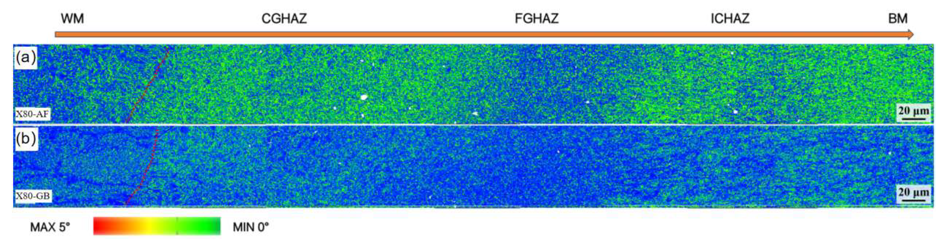

Table 1.
Chemical Composition of X80 Pipeline Steel Base Material (Mass Fraction, %).
| No. | C | Mn | Cr | Ni | Mo | V | Ti | Nb | Pcm |
|---|---|---|---|---|---|---|---|---|---|
| X80-AF | 0.056 | 1.83 | 0.195 | 0.120 | 0.090 | 0.004 | 0.014 | 0.054 | 0.160 |
| X80-GB | 0.060 | 1.74 | 0.206 | 0.114 | 0.078 | 0.003 | 0.012 | 0.061 | 0.164 |
Table 2.
Welding Parameters for the X80 girth weld.
| Welding Pass | Welding Method | Filler Metal | Polarity | Current (A) |
Voltage (V) |
Shielding Gas Flow Rate (L/min) |
Travel Speed (cm/min) |
Heat Input (kJ/mm) |
|---|---|---|---|---|---|---|---|---|
| Root weld | GTAW | ER70S-6 | DCEP | 100-160 | 10-16 | 15-20 | 6-12 | 0.81-1.43 |
| Hot pass | FCAW-G | E91T1-K2M | DCEP | 160-260 | 20-26 | 20-35 | 12-24 | 1.26-1.97 |
| Filling passes | FCAW-G | E91T1-K2M | DCEP | 140-260 | 20-26 | 20-35 | 12-24 | 1.42-2.05 |
| Cap passes | FCAW-G | E91T1-K2M | DCEP | 140-240 | 20-26 | 20-35 | 8-18 | 1.38-1.90 |
Table 3.
Effective grain size (equivalent circle diameter) of base metal.
| Location | No. | Grain size (μm) | ||
|---|---|---|---|---|
| Minimum | Maximum | Average | ||
| Base metal | X80-AF | 2.68 | 19.3 | 4.31 |
| X80-GB | 2.65 | 23.3 | 5.15 | |
Table 4.
FGHAZ Effective Grain Size (Equivalent Circle Diameter).
| Location | No. | Grain size (μm) | ||
|---|---|---|---|---|
| Minimum | Maximum | Average | ||
| FGHAZ | X80-AF | 2.63 | 14. 23 | 3.72 |
| X80-GB | 2.62 | 17.65 | 4.92 | |
Disclaimer/Publisher’s Note: The statements, opinions and data contained in all publications are solely those of the individual author(s) and contributor(s) and not of MDPI and/or the editor(s). MDPI and/or the editor(s) disclaim responsibility for any injury to people or property resulting from any ideas, methods, instructions or products referred to in the content. |
© 2026 by the authors. Licensee MDPI, Basel, Switzerland. This article is an open access article distributed under the terms and conditions of the Creative Commons Attribution (CC BY) license.
Copyright: This open access article is published under a Creative Commons CC BY 4.0 license, which permit the free download, distribution, and reuse, provided that the author and preprint are cited in any reuse.


