
Submitted:
28 January 2026
Posted:
28 January 2026
You are already at the latest version
Abstract
Floating involute splines are widely used in aviation power transmission systems to transmit torque. In this paper, by establishing a finite element model of the dynamic deformation of the floating involute spline shaft, the influence of the dynamic deformation of the spline shaft on the misalignment state of the spline pair under various typical dynamic overloads was analyzed. And a contact simulation model of the floating spline pair with the actual tooth profile was established to study the influence of the spline misalignment caused by dynamic deformation on the contact pressure distribution on the tooth surface. The contact stress fatigue strength of the spline pair under dynamic loads such as limit loads and ultimate loads was evaluated. The results show that the axial overload can lead to the axial movement of the mating surface of the floating spline, reducing the effective axial contact length; the radial overload and gyroscopic moment can lead to the parallel misalignment and angular misalignment of the spline. When the overloads are superimposed, the angular misalignment of the spline is the most significant under the limit load, and the parallel misalignment is the most significant under the ultimate load. There are obvious stress concentrations and uneven load-bearing in the contact stress distribution of the spline under the limit and ultimate loads. According to the infinite life and static strength design methods, the evaluation shows that the long-term working contact fatigue strength of the floating spline of a certain type of engine under the ultimate load does not meet the design requirements, and the spline parameters need to be optimized. The quantitative analysis method for the misalignment of the floating spline under the superposition of various dynamic loads formed in this paper provides an important theoretical reference for the design of the misalignment of the aviation floating spline and the improvement of its long-term working ability.
Keywords:
floating involute spline
; limit loads
; ultimate loads
; dynamic deformation
; misalignment
; contact stress
1. Introduction
In the design of aero-engine transmission systems, various couplings are employed to transmit torque. To enhance the thrust-to-weight ratio of the engine and improve the safety and reliability of the transmission system, couplings are required to possess characteristics such as lightweight construction, low cantilever moment, high-speed capability, high balancing potential, acceptable centrifugal stress, and good misalignment compensation capability [1]. Due to their compact structure, ease of installation, minimal weakening effect on shaft and hub strength, and ability to compensate for installation errors and misalignment, aerospace splines have found extensive application in aero-engine structural design. For instance, a single US A-4 Skyhawk attack aircraft incorporates 174 splined connection structures [2].
However, aerospace splines operate under diverse conditions. In addition to enduring complex environmental loads, they are subjected to various mechanical loads including centrifugal force, constant torque, periodic torque, additional cyclic torsional loads, transient peak torque, impact torque, misalignment loads, and resonance [3]. These factors lead to widespread issues such as contact wear, contact fatigue, and even failure during extended operation or testing. For floating involute splines, misalignment is a critical factor causing uneven load distribution, reduced load-carrying capacity, increased contact stress, contact wear, and contact fatigue failure [2]. Data surveys from the US Navy aircraft maintenance repository indicate that spline connection problems exist in 40% of fixed-wing aircraft and 70% of rotary-wing aircraft [1], primarily involving misalignment-induced wear. During actual operation, misalignment issues arising from the coupling of various factors result in only 25% to 50% of the spline teeth engaging in meshing. Therefore, the misalignment problems in service splines and the factors driving their changes necessitate in-depth analysis.
Contact analysis is the basic work to obtain the effect of floating spline misalignment on the load carrying capacity, therefore, many scholars have carried out theoretical calculations on the contact characteristics [4,5] and load distribution [6,7] of spline joints, as well as test studies on the contact pressure [8,9]and contact stiffness [10]. Regarding the contact characteristics of aerospace spline misalignment, Cura et al. [11] investigated the effect of radial misalignment angle on the load distribution between the teeth of the spline sub-tooth, and Cuffaro, Cura et al. [12] analyzed in detail the effect of the magnitude of angular misalignment and the type of lubrication of the key of the spline sub-tooth on the micromotor wear of the spline teeth of different shapes. Medina et al. [13] analyzed the contact pressure and contact stiffness of the teeth of an angular eccentric spline based on the boundary element method. Hong et al. [14] analyzed the tooth contact load distribution law of misaligned spline based on the finite element method. Zhang C et al. [15] conducted a study on the load distribution of splines under static misalignment and dynamic misalignment conditions. Xiao L et al. [16] studied the influence mechanism of misalignment on the wear of spline couplings. In addition, some scholars [17,18,19] have carried out theoretical modeling and research on the system dynamics of the spline coupling combined with the connected rotor.
In summary, scholars both at home and abroad have carried out extensive research and achieved fruitful results in aspects such as spline contact analysis, analysis of the impact of misalignment, and dynamic analysis of rotating systems. However, the following problems still exist:
First, for (military) aero-engines, during aircraft flight, landing, catapult takeoff, and various maneuvering flights, the inertial loads cause the floating involute spline shafts in operation to produce maneuvering deformations of varying degrees, which have an obvious impact on the misalignment state of the floating spline pairs. At present, there are few literatures mentioning the connection state and contact fatigue strength of spline pairs under the comprehensive consideration of such loads. Second, using simplified spline tooth profiles for contact analysis makes it difficult to accurately obtain the distribution and magnitude of the contact stress on the tooth surface.
Therefore, this paper establishes a finite element model for the maneuvering-induced deformation of floating involute spline shafts. It analyzes the impact of deformation issues caused by various typical maneuvering loads on the misalignment state of spline couplings. Based on a contact simulation model of the spline coupling incorporating true tooth profiles, the study investigates the influence of spline misalignment resulting from maneuvering deformation on the distribution of contact pressure across tooth flanks. Furthermore, it conducts assessments of contact stress fatigue strength for the spline coupling under maneuvering loads, including limited and ultimate load conditions. This work provides a basis for the optimal design of floating spline structures and the prediction of their contact fatigue life.
2. Floating Spline Vice Maneuvering Load Analysis
Maneuvering loads refer to the mass inertial forces at the center of mass of engine components, the mass inertial moments around the engine’s center of mass, and the gyroscopic moments of rotating parts, which are caused when an aircraft is in flight, landing, catapult takeoff, and various maneuvering flights. Under the combined action of these loads, the floating spline shaft will undergo maneuvering deformation, resulting in misalignment in the fitting state of the floating spline pair, as shown in Figure 1.
This paper mainly studies the influence of maneuvering loads such as mass inertial forces and gyroscopic moments on the misalignment of floating spline pairs. It calculates and analyzes the maneuvering deformation of the floating spline shaft under maneuvering loads, extracts the misalignment amounts of the spline pair under different maneuvering loads, and further studies the influence of the misalignment amounts caused by maneuvering loads on the contact stress of the spline pair.
The misalignment types of a floating spline pair can be categorized into three cases: angular misalignment, radial misalignment, and axial misalignment, as illustrated in Figure 2. The corresponding symbols defining the misalignment magnitudes are given in Table 1. Figure 3 depicts the Cartesian coordinate system employed for analyzing the maneuver loads on the floating spline. The X-axis coincides with the rotational axis of the spline shaft, with the positive direction defined from the internal spline towards the external spline. The Z-axis is oriented vertically downward (positive downward). The Y-axis is determined by the right-hand rule, oriented positively to the right along the X-axis. ω denotes the rotational angular velocity of the spline shaft. The inertial force overloads acting on the floating spline are decomposed into axial, vertical, and horizontal directions. Since the vertical and horizontal overloads exert identical influences on floating spline misalignment, they are consolidated herein as the radial overload. Similarly, the gyroscopic moments of the spline shaft are decomposed into vertical and horizontal yaw components, which also exhibit equivalent effects on spline misalignment; consequently, they are combined into a single yaw rate. Synthesizing the above considerations, the defined overload types for the floating spline and their corresponding symbols are presented in Table 2. Figure 4 provides a schematic representation of the maneuver loads acting on the floating spline. It is crucial to note that the vector directions of the radial overload and the gyroscopic moment are aligned, resulting in the most hazardous superimposed misalignment effect under this condition. The calculation formulas for the inertial force and gyroscopic moment listed in Table 2 are referenced as [20]:
where: m is the spline shaft mass; g is the gravitational acceleration; J is the spline shaft moment of inertia.

Table 3.
Motorized overload stacking factors for typical operating scenarios with floating splines.
| Working scenario | /g | /g | (rad/s) |
| Ultimate load 1 | 0 | 1 | 3.5 |
| Ultimate load 2 | 0 | 1 | -3.5 |
| Limit load 1 | 0 | 10 | 1.4 |
| Limit load 2 | 0 | 10 | -1.4 |
| Limit load 3 | 5.5 | 0 | 1.4 |
| Limit load 4 | 5.5 | 0 | -1.4 |
3. Spline Misalignment Analysis Method
During actual flight operations, an aircraft engine encounters various working scenarios involving superimposed maneuver loads. To facilitate the analysis of maneuver-induced deformations in the floating spline shaft under these multiple scenarios, the misalignment matrix [U] of the spline pair under a unit maneuver load is first computed. This matrix is then multiplied by the operational condition matrix [V] representing the superimposed maneuver loads. This yields the misalignment matrix [W] of the spline pair under various superimposed maneuver load conditions:
(4)
The selected unit motorized loads are shown in Table 4, where Ω is the spline shaft rotational speed for the steady-state maximum speed, which is a purely numerical value with no physical significance.
The schematic diagram of a typical floating spline shaft structure in an aero-engine is shown in Figure 5. It mainly consists of an internal spline shaft and an external spline shaft. The internal spline shaft is supported on the casing through a roller bearing K1 and a ball bearing K2, while the external spline shaft is supported on the casing through a ball bearing K4. The two shafts realize the transmission of operating torque and mutual support through a floating spline coupling K3.
Finite element analysis was employed to investigate the maneuver deformation of a floating splined shaft under unit maneuver load. The mechanical model established for analyzing the maneuver deformation of the floating spline is shown in Figure 6. A radial grounded bearing element was defined at the roller bearing K1. Radial and axial grounded bearing elements were defined at the ball bearings K2 and K4. The spline coupling K3 was modeled with an intermediate bearing element simulating radial support between the two components. In the figure, the subscript R denotes radial support stiffness, and the subscript X denotes axial support stiffness. The required splined shaft support stiffness parameters for the calculation are listed in Table 5. The bearing support stiffness is determined by the stiffness of the bearings and the supporting stator casing. The formula for calculating the radial stiffness of the spline [20]is given below:
\ (5)
where: refer to Figure 7, z is the number of spline teeth; is the circumferential angle of the contact point of the i-th tooth of the spline located on the radius of the pitch circle; φ is the contact pressure angle of the spline; is the normal stiffness of the spline, which can be obtained by first calculating the displacement (i.e., compliance) of the single-tooth model caused by applying a unit load in the normal direction, and then taking its reciprocal.
In the finite element model, apply the unit dynamic loads listed in Table 4 respectively, and calculate the misalignment amount of the floating spline under the unit dynamic loads. Collate the calculated data to form the spline pair misalignment matrix [U], which is specifically expressed as:
where: the data superscript X in the first column of the matrix [U] denotes the misalignment due to unit axial overload, the data superscript R in the second column denotes the misalignment due to unit radial overload, and the data superscript in the third column denotes the misalignment due to unit gyroscopic moment; and the data in the first row of the matrix [U] is the axial misalignment, the data in the second row is the radial misalignment, and the data in the third row is the angular misalignment.
Based on the motorized overload stacking coefficients listed in Table 3, the motorized load stacking combined conditions matrix [V] is formed as:
where: the data in the first and second columns of the matrix [V] represent the ultimate load superposition coefficients, and the data in the third to sixth columns represent the extreme limit load superposition coefficients; the data in the first row of the matrix [V] is the axial overload coefficients, the second row is the radial overload coefficients, and the third row is the gyroscopic moment overload coefficients.
According to Formula (4), the matrix [W] of spline pair misalignment under the superposition of dynamic loads can be calculated, which can be expressed as:
In the formula, the first and second columns of matrix [W] represent the spline pair misalignment amounts under ultimate load 1 and ultimate load 2, respectively, while the third to sixth columns represent the spline misalignment amounts under limiting load 1 to limiting load 4. The first row of matrix [W] corresponds to the axial misalignment amount, the second row to the radial misalignment amount, and the third row to the angular misalignment amount.
The angular misalignment of the spline is limited by the radial float of the floating spline, . Normally the design float of the floating spline has the following relationship with the parallel misalignment and angular misalignment:
where: is the design float of the floating spline; is the contact length of the floating spline.
If is greater than the radial float of the spline , interference occurs, which restricts the angular misalignment of the spline, in which case the angular misalignment is:
where: is the spline angular misalignment at the time of interference.
As a result, the spline interference and the angular misalignment after the interference are determined by Equations (9) and (10), which corrects the angular misalignment value in the matrix [W].
4. Simulation Analysis of Misalignment of Floating Spline Pair Under Dynamic Overload
Taking a certain type of engine floating spline as an example, the main characteristic structures of the internal and external spline shafts of the floating spline are extracted. The established finite element model for the dynamic deformation of the floating involute spline is shown in Figure 8. The input support stiffness parameters for the dynamic deformation analysis of the spline shaft are listed in Table 6, where κ represents the true value of the support stiffness, which is a pure numerical value without physical meaning. The structural parameters and material parameters of the floating spline are shown in Table 7 and Table 8, respectively.
Figure 9 presents the maneuver-induced deformation analysis results of the spline shaft under an axial overload condition of N_X = 1g. It is evident that the deformation primarily manifests as axial displacement. The axial deformation results of the spline pair extracted at this state are shown in Figure 10. The results indicate an axial float displacement (u_x) of the spline pair equal to 0.029 mm. At this point, both the parallel misalignment and angular misalignment of the spline pair are negligible. The axial float displacement is defined as the average value of the relative axial deformation between the spline pair members. A positive value indicates that the axial deformation of the internal spline exceeds that of the external spline, while a negative value signifies the opposite
Figure 9.
Clouds of motorized deformation of floating spline shaft under axial overload
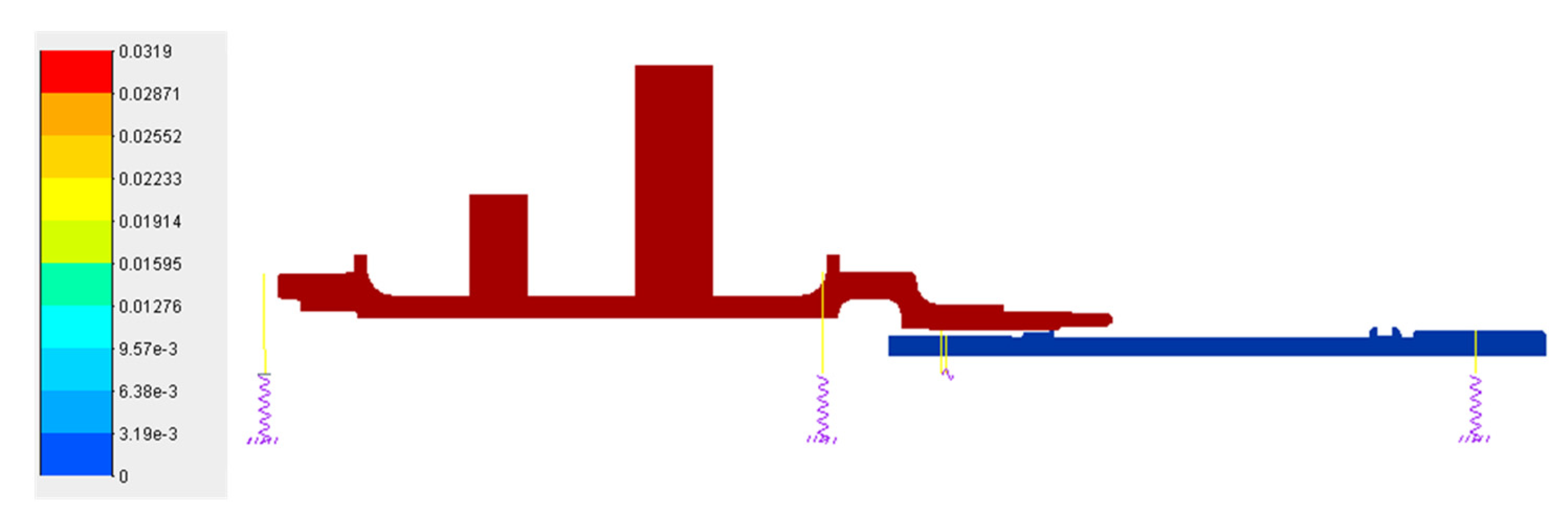
Figure 10.
Maneuvering deformation of floating spline pair under axial overload
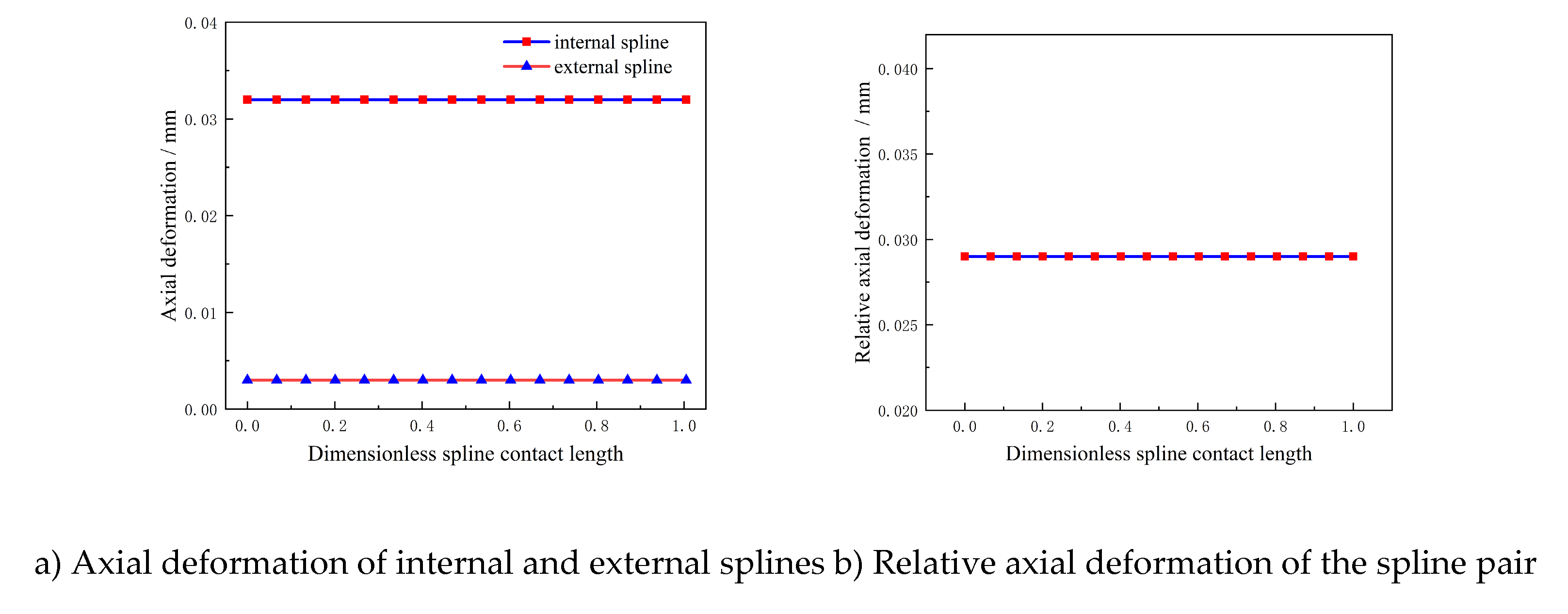
Figure 11 shows the analysis results of the spline shaft’s maneuvering deformation under a radial overload of = 1g. It can be seen that the maneuvering deformation of the spline shaft is mainly radial and angular deformation. The radial deformation results of the spline pair at this time are extracted as shown in Figure 12. The results indicate that the parallel misalignment e of the spline pair is 0.002 mm, and the angular misalignment α is 0.007°. At this time, the axial movement of the spline pair is extremely small and can be ignored. Among them, the parallel misalignment is the average value of the relative radial deformation of the spline pair, and the angular misalignment is the arctangent value of the slope of the relative radial deformation curve of the spline pair. The positive and negative values of the angle are consistent with the positive and negative values of the curve slope.
Figure 11.
Motorized deformation of floating spline shaft with radial overload
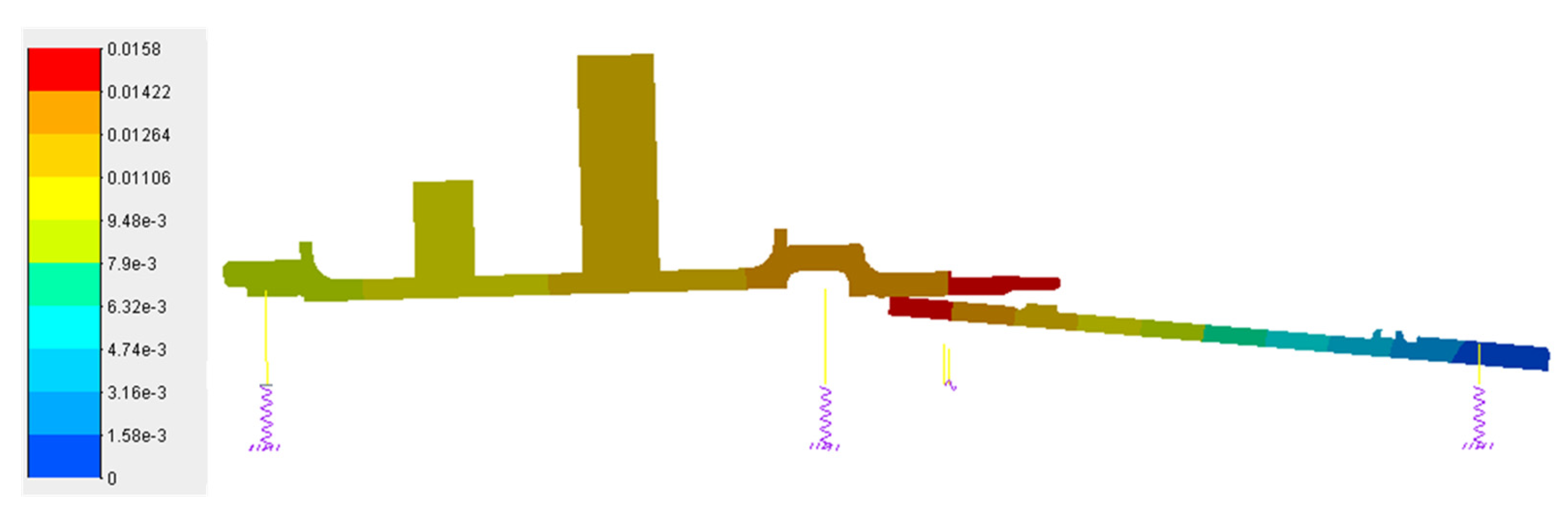
Figure 12.
Maneuvering deformation of floating spline pair with radial overload
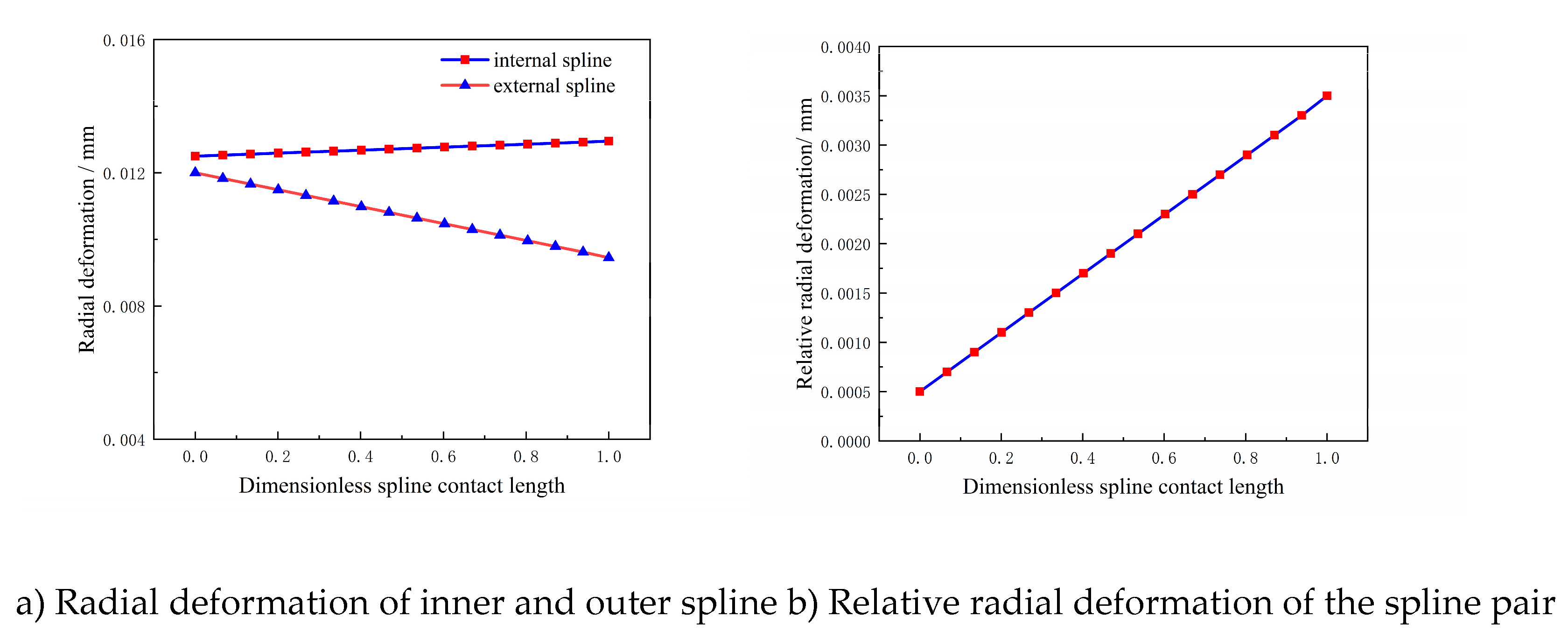
Figure 13 presents the maneuver deformation analysis results of the spline shaft under a gyroscopic moment ω_θ = 1 rad/s. It is shown that the primary manifestations of the spline shaft’s maneuver deformation are radial and angular deformation. The radial deformation results of the spline pair extracted at this condition are illustrated in Figure 14. The results indicate a parallel misalignment e of -0.005 mm and an angular misalignment α of -0.045° for the spline pair. The axial float at this point is minimal and negligible. Here, the parallel misalignment is defined as the average value of the relative radial deformation of the spline pair, while the angular misalignment is calculated as the arctangent of the slope of the relative radial deformation curve. The sign of the angular misalignment corresponds to the sign of the curve’s slope.
Figure 13.
Floating spline shaft maneuvering deformation at gyroscopic moment angular velocity
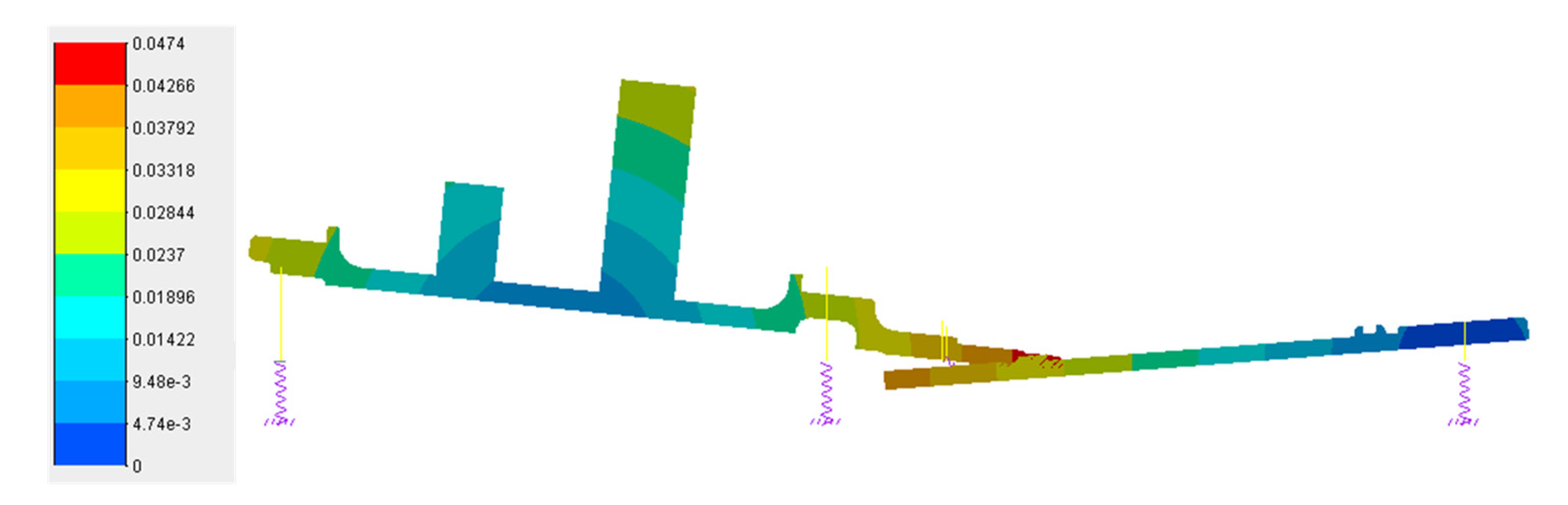
Figure 14.
Maneuvering deformation of floating spline sub with gyroscopic moment angular velocity
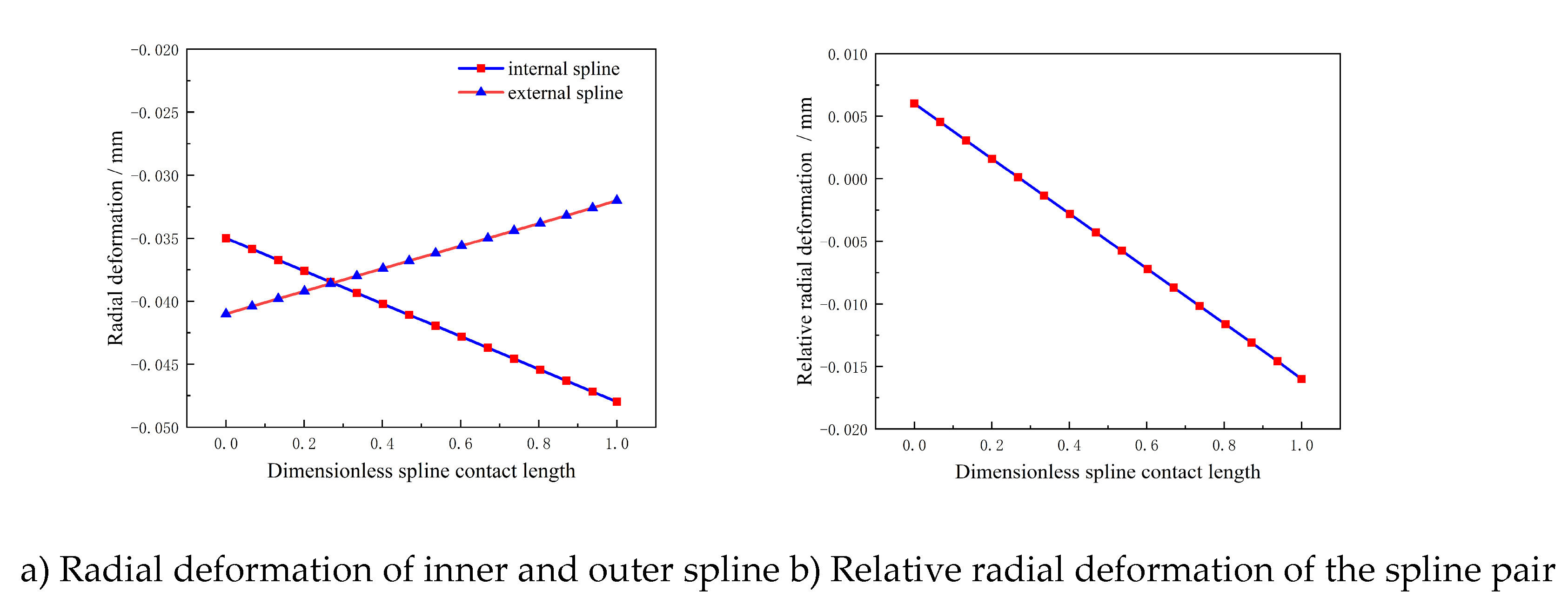
Figure 15.
Dynamic deformation of the lower floating spline pair under the superposition of dynamic overload.
Figure 15.
Dynamic deformation of the lower floating spline pair under the superposition of dynamic overload.
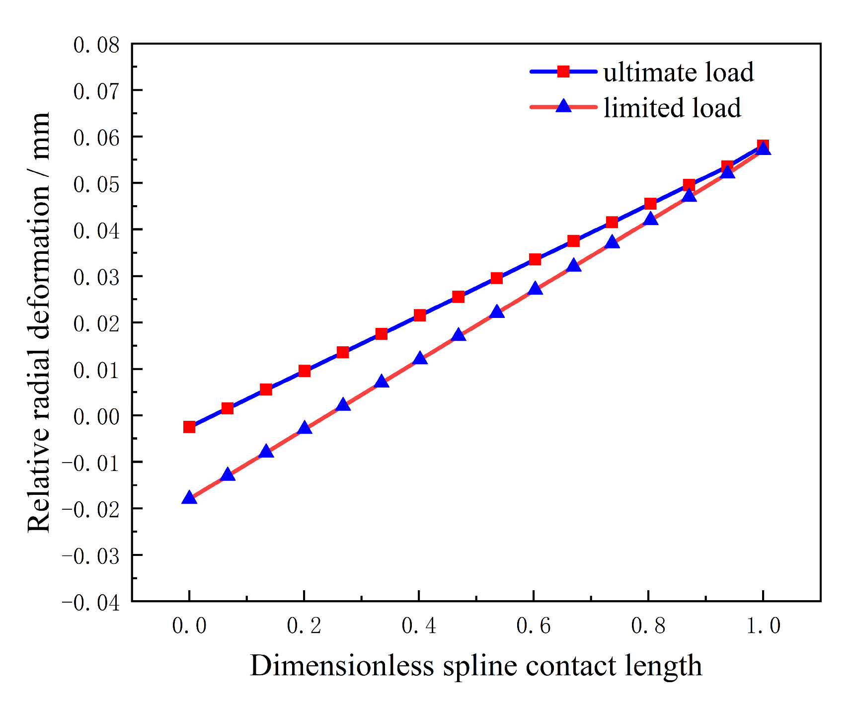
Table 9.
Calculation results of floating spline misalignment per unit motorized load.
| Dynamic load | Axial misalignment (mm) | Parallel misalignment (mm) | Angular misalignment (°) |
| =1g | 0.029 | 0 | 0 |
| =1g | 0 | 0.002 | 0.007 |
| =1rad/s | 0 | -0.005 | -0.045 |
Table 10.
Calculation results of floating spline misalignment under the superposition of dynamic overload.
Table 10.
Calculation results of floating spline misalignment under the superposition of dynamic overload.
| Working scenario | Ultimate load 1 | Ultimate load 2 | Limit load 1 | Limit load 2 | Limit load 3 |
Limit load 4 |
| Axial misalignment (mm) |
0 | 0 | 0 | 0 | 0.16 | 0.16 |
| Parallel misalignment (mm) | -0.016 | 0.020 | 0.013 | 0.027 | -0.007 | 0.007 |
| Angular misalignment (°) | -0.151 | 0.165 | 0.007 | 0.133 | -0.063 | 0.063 |
Table 12.
Floating Spline Socket Mating Interference Check Results.
| Working scenario | Designed floating amount /mm | Radial floating amount/mm | Whether there is interference |
| Ultimate load 2 | 0.058 | 0.08 | No |
| Limited load 2 | 0.057 | 0.08 | No |
5. Simulation Analysis of Tooth Surface Contact of Floating Involute Spline Pair Under Dynamic Overload
In the previous section, aiming at the typical floating spline shaft structure of aero-engines, an analysis of the misalignment of the spline contact pair under dynamic overload was carried out. In the following, the finite element method is adopted to separately extract the internal and external spline contact pairs, so as to study the influence of the misalignment of the floating spline pair on the tooth surface contact characteristics under the superposition of dynamic overload, and evaluate the contact stress and fatigue strength.
The tooth surface contact analysis of the floating spline pair was conducted using the finite element method. A finite element model for the tooth surface contact of the spline pair was established with reference to Figure 16. A steady-state maximum torque load was applied to the input end of the external spline, a fixed support constraint was imposed on the output end of the internal spline, and a standard frictional contact was set up on the meshing tooth surfaces of the internal and external splines. To reduce the impact of loads and boundaries on the simulation results of the contact pair, in accordance with Saint-Venant’s principle, the lengths of the spline input shaft and output shaft were set to 3 times the meshing contact length of the spline tooth surfaces. To realistically simulate the meshing behavior of the actual involute spline tooth profile, a real model with geometric features such as fillets and chamfers on the spline tooth surfaces was selected for finite element modeling. Mesh refinement was performed at the tooth surface contact positions and the tooth root fillet areas. Due to the complex structure of local fillets and chamfers, which makes it difficult to achieve structured meshes, tetrahedral elements with mid-nodes were adopted. In addition, a study on the independence of tooth surface mesh size was carried out. Considering both calculation accuracy and efficiency, a mesh size of 0.1 mm was chosen for the tooth surfaces, as shown in Figure 17.
The internal and external splines were taken as the contact surface and target surface, respectively. To prevent mesh penetration during the simulation, symmetric contact was established. The contact friction coefficient was assumed to be 0.1. Based on engineering experience, this friction coefficient is reasonable because the spline operates in an oil mist or oil-gas environment with self-lubrication. When conducting the tooth surface contact analysis of a floating involute spline pair under maneuvering overload, the misalignment amounts of the floating spline under the ultimate load and limited load specified in Table 11 are artificially set during the assembly process of the internal and external splines. Both the angular misalignment and parallel misalignment occur in the positive Z-direction as shown in Figure 17. The contact state is checked to ensure that no tooth surface contact interference occurs. To facilitate the explanation of the influence of misalignment on the contact load distribution of each tooth surface, the external spline teeth are numbered according to Figure 18.
Figure 19 and Figure 20 respectively show the cloud diagram of maximum contact pressure, maximum contact pressure and contact load force on each tooth surface of the external spline under ultimate load 2. Both angular misalignment and parallel misalignment under ultimate load 2 occur in the positive direction of the Z-axis. As shown in Figure 19: the external spline at teeth No. 6, 7, 15 and 16 has relatively large stress at the input end, with obvious stress concentration. These positions are located in the positive direction of the Z-axis where angular misalignment and parallel misalignment occur, as well as in the opposite negative direction. For the other teeth, the relatively large stress occurs near the output end, but not at the outermost output end. Figure 20 and Figure 21 show that the spline has obvious stress concentration and uneven load distribution. The relatively large contact pressure and large meshing contact load force of the spline occur at teeth No. 6, 7, 15 and 16. Among them, the contact stress at tooth No. 7 is the maximum, reaching 1980 MPa, and this tooth bears the maximum contact load force of 3.5 kN. Angular misalignment reduces the contact area of the spline, resulting in relatively large stress concentration. Parallel misalignment reduces the backlash of the spline pair, and the tooth with the smallest backlash meshes first and bears the largest load. This position should be located in the positive direction of the Z-axis where parallel misalignment occurs, followed by the negative direction of the Z-axis, corresponding to teeth No. 7 and 16 in the calculation results of this paper, respectively.
a) Maximum contact pressure b) Contact force
Figure 21 to 22 respectively show the cloud diagram of maximum contact pressure, maximum contact pressure and contact load force on each tooth surface of the external spline under limit load 2. Both angular misalignment and parallel misalignment under restricted load 2 occur in the positive direction of the Z-axis. It can be seen from Figure 22 that the external spline at teeth No. 6, 7, 15 and 16 has relatively large stress at the input end, with obvious stress concentration. These positions are located in the positive direction of the Z-axis where angular misalignment and parallel misalignment occur and the opposite negative direction of the Z-axis, while the relatively large stress on other teeth occurs near the output end. Figure 23 and Figure 24 show that the spline has obvious stress concentration and uneven load distribution. The relatively large contact pressure and large meshing contact load force of the spline occur at teeth No. 6, 7, 15 and 16. Among them, the contact stress at tooth No. 7 is the maximum, reaching 1680 MPa, and this tooth bears the maximum contact load force of 3.2 kN. Angular misalignment reduces the contact area of the spline, resulting in relatively large stress concentration. Parallel misalignment reduces the backlash of the spline pair, and the tooth with the minimum backlash meshes first and bears the maximum load. This position should be located in the positive direction of the Z-axis where parallel misalignment occurs, followed by the negative direction of the Z-axis, corresponding to teeth No. 7 and 16 in the calculation results of this paper, respectively.
a) Maximum contact pressure b) Contact force
Considering that the circumferential tooth-by-tooth load distribution of the spline changes during maneuvering deformation, each rotation subjects the spline to one load cycle. Fatigue life assessment is therefore required. In accordance with the requirements described in Section 1.2 regarding maneuvering overload usage, the floating spline must be capable of long-term service under limit load conditions, and short-term operation under ultimate load conditions. Accordingly, the contact stress of the floating spline under the limit load is assessed. Here, an infinite life assessment is applied, requiring compliance with the following formula:
where:is the contact fatigue limit of the floating spline, which is related to the gear material and surface processing state and is usually measured by experiments; is the maximum contact pressure under the action of spline limited load maneuvering deformation; is the spline long-term working wear life coefficient, which is generally taken as 0.8~0.9 according to engineering experience [22].
To evaluate the contact stress of the floating spline under the spline limited load, the following formula must be satisfied for static strength assessment:
where: is the maximum contact pressure under the action of spline limited load maneuvering deformation; is the static strength contact life coefficient. For structural steel, quenched and tempered steel, and carburized and quenched carburized steel, = 1.6 [23]; for nitrided steel (after nitriding), quenched and tempered steel, and carburized steel, = 1.3 [23]; for quenched and tempered steel and carburized steel after nitrocarburizing, = 1.1 [23]; is the tooth surface work hardening coefficient, with = 1.2~1.0 [23].
Based on Formula (11) and Formula (12), the evaluation results are shown in Table 13. The results indicate that the long-term working contact fatigue strength of the floating spline under the limited load working scenario does not meet the design requirements, while the short-term working of the floating spline under the limit load working scenario meets the strength design. Therefore, it is suggested that the spline parameters need to be optimized during the design of the floating spline to meet the long-term working requirements.
6. Conclusions
The main conclusions of this study are as follows:
1) By coupling the maneuvering deformation and misalignment that occur in the actual working state of the floating spline, the quantitative analysis of the floating spline misalignment under the superposition of multiple maneuvering loads is realized.
2) Axial overload can cause axial slippage on the mating surfaces of the floating spline, reducing the effective axial contact length. Radial overload and gyroscopic torque can lead to parallel misalignment and angular misalignment, with the misalignment caused by gyroscopic torque being more significant.
3) The analysis results of the misalignment of the floating spline under the superposition of maneuvering overload show that under the ultimate load 2, the maximum angular misalignment is 0.165°, followed by the parallel misalignment of 0.02 mm; under the limited load 2, the maximum parallel misalignment is 0.027 mm, followed by the angular misalignment of 0.133°; under both limited load 3 and limited load 4, the maximum axial misalignment is 0.16 mm, while the parallel misalignment and angular misalignment are at relatively small values. The axial misalignment of 0.16 mm is comparable to the allowable assembly error.
4) The analysis of contact stress of the floating spline pair under more severe ultimate and limited loads reveals obvious stress concentration and uneven load-bearing phenomena. Larger contact pressure and meshing contact load force occur on the teeth numbered 6, 7, 15, and 16, which are located near the positive and negative directions of the Z-axis where parallel misalignment occurs. The maximum contact stress on the tooth surface under the ultimate load is 1980 MPa, and that under the limited load is 1680 MPa.
5) In accordance with the load application requirements and the design methods for infinite life and static strength, the evaluation shows that the long-term operating contact fatigue strength of the floating spline in a certain type of engine under limited loads does not meet the design requirements, and it is necessary to optimize the design of the spline parameters. The formed quantitative analysis method for the misalignment of floating splines under the superposition of multiple maneuvering overloads provides an important theoretical reference for the misalignment design of aviation floating splines and the improvement of their long-term operating capability.
References
- Zhao, G.; Zhao, X.; Qian, L.; Yuan, Y.; Ma, S.; Guo, M. A review of aviation spline research. Lubricants 2022, 11(1), 6. [Google Scholar] [CrossRef]
- Brown, H.W. A reliable spline coupling. Journal of Engineering for Industry 1979, 101(4), 421–426. [Google Scholar] [CrossRef]
- Boyce, M.P. The Gas Turbine Engineering Handbook, 3rd ed.; Gulf Professional Publishing: Boston, 2006. [Google Scholar]
- Xue, X.; Yu, W.; Lin, K.; Zhang, N.; Xiao, L.; Jiang, Y. Design Method and Teeth Contact Simulation of PEEK Involute Spline Couplings. Materials 2023, 17(1), 60. [Google Scholar] [CrossRef] [PubMed]
- Li, S. Contact analysis and strength calculations of involute spline couplings. Scientific Reports 2023, 13(1), 384. [Google Scholar] [CrossRef] [PubMed]
- Yang, D.C.H.; Tong, S.H. On the profile design of transmission splines and keys. Mechanism and Machine Theory 2007, 42(1), 82–87. [Google Scholar] [CrossRef]
- Hong, J.; Talbot, D.; Kahraman, A. A semi-analytical load distribution model for side-fit involute splines. Mechanism and Machine Theory 2014, 76(6), 39–55. [Google Scholar] [CrossRef]
- Cuffaro, V. Prediction method for the surface damage in splined couplings; Polytechnic University of Turin: Turin, Italy, 2013. [Google Scholar]
- Cuffaro, V.; Cura, F.; Mura, A. Analysis of the pressure distribution in spline couplings. Mechanical Engineering Science 2012, 226(12), 2852–2859. [Google Scholar] [CrossRef]
- Li, Y.; Zhao, G.; Yuan, Y. Simulation and Test of Contact Stiffness of Aviation Splines. Chinese Journal of Aerospace Power 2024, 39(12), 187–194. [Google Scholar]
- Cura, F.; Mura, A.; Gravina, M. Load Distribution in Spline Coupling Teeth with Parallel Offset Misalignment. Proceedings of the Institution of Mechanical Engineers, Part C: Journal of Mechanical Engineering Science 2013, 227(10), 2195–2205. [Google Scholar] [CrossRef]
- Cuffaro, V.; Cura, F.; Mura, A. Test Rig for Spline Couplings Working in Misaligned Conditions. Journal of Tribology 2014, 136(1). [Google Scholar] [CrossRef]
- Medina, S.; Olver, A.V. An analysis of misaligned spline couplings. Journal of Engineering Tribology 2002, 216(5), 269–278. [Google Scholar] [CrossRef]
- Hong, J.; Talbot, D.; Kahraman, A. Load distribution analysis of clearance-fit spline joints using finite elements. Mechanism and Machine Theory 2014, 74, 42–57. [Google Scholar] [CrossRef]
- Zhang, C.; Zhu, R.; Chen, W.; Wang, D.; Yin, X.; Song, D. An improved dynamic model of the spline coupling with misalignment and its load distribution analysis. International Journal of Mechanics and Materials in Design 2024, 20(2), 393–408. [Google Scholar] [CrossRef]
- Xiao, L.; Xu, Y.; Sun, X.; Xu, H.; Zhang, L. Experimental investigation on the effect of misalignment on the wear failure for spline couplings. Engineering Failure Analysis 2022, 131, 105755. [Google Scholar] [CrossRef]
- Xue, X.; Huo, Q.; Liu, J.; Jia, J. Nonlinear dynamic load analysis of aviation spline coupling with mass eccentricity and misalignment. Advances in Mechanical Engineering 2021, 13(2), 1687814021996511. [Google Scholar] [CrossRef]
- Zhang, C.; Cao, P.; Zhu, R.; Chen, W.; Wang, D. Dynamic modeling and analysis of the spline joint-flexible coupling-rotor system with misalignment. Journal of Sound and Vibration 2023, 554, 117696. [Google Scholar] [CrossRef]
- Dai, Z.; Jing, J.; Chen, C.; Cong, J. Extensive experimental study on the stability of rotor system with spline coupling. Turbo Expo: Power for Land, Sea, and Air 2018, 51135, V07AT33A021. [Google Scholar]
- Editorial Board of Aeroengine Design Manual. Aeroengine Design Manual; Aviation Industry Press: Beijing, 2000. [Google Scholar]
- General Specification for Aircraft Turbofan and Turbojet Engines. 2010. Available online: https://www.cssn.net.cn/.
- Zhang, Q.G. Aeroengine Strength Design and Test Manual: Overall Structural Strength of Engines; National Defense Industry Press: Beijing, 1981. [Google Scholar]
- Calculation of Tooth Surface Contact Fatigue Strength for Aviation Involute Cylindrical Gears. 1984. Available online: https://www.cssn.net.cn/.
Figure 1.
Schematic diagram of maneuvering deformation under gyroscopic moment of a typical floating spline shaft of an aero-engine.
Figure 1.
Schematic diagram of maneuvering deformation under gyroscopic moment of a typical floating spline shaft of an aero-engine.
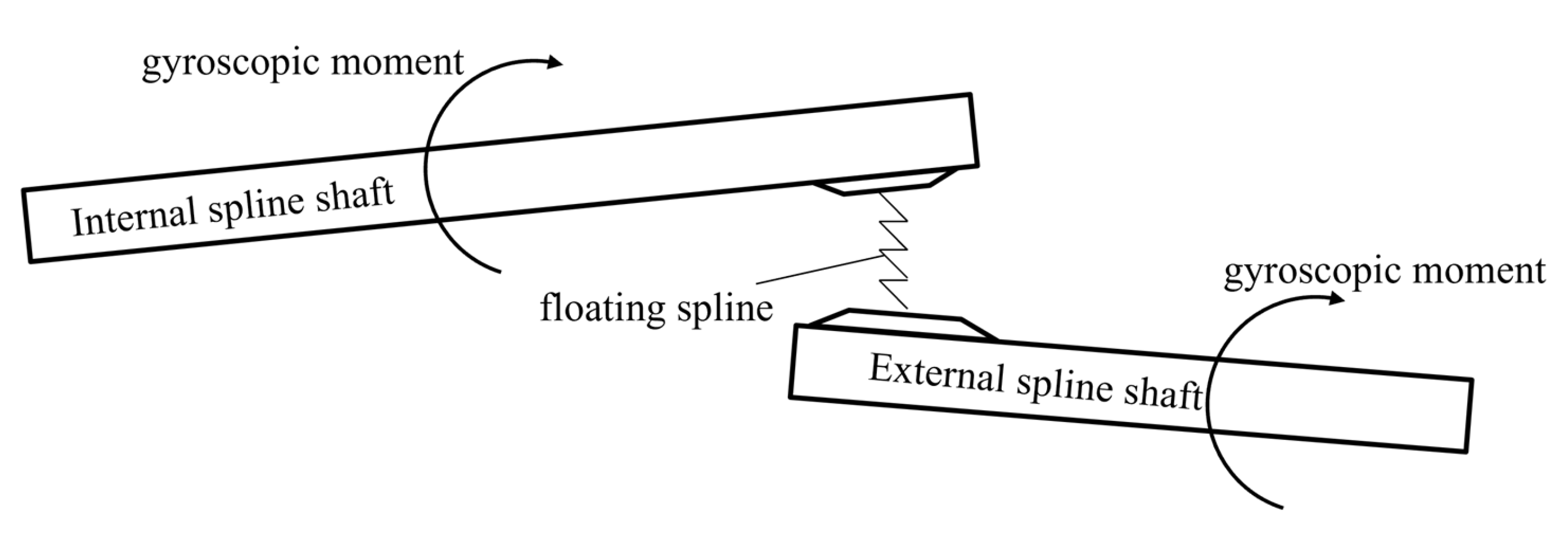
Figure 2.
Schematic diagram of misalignment of floating spline pair.
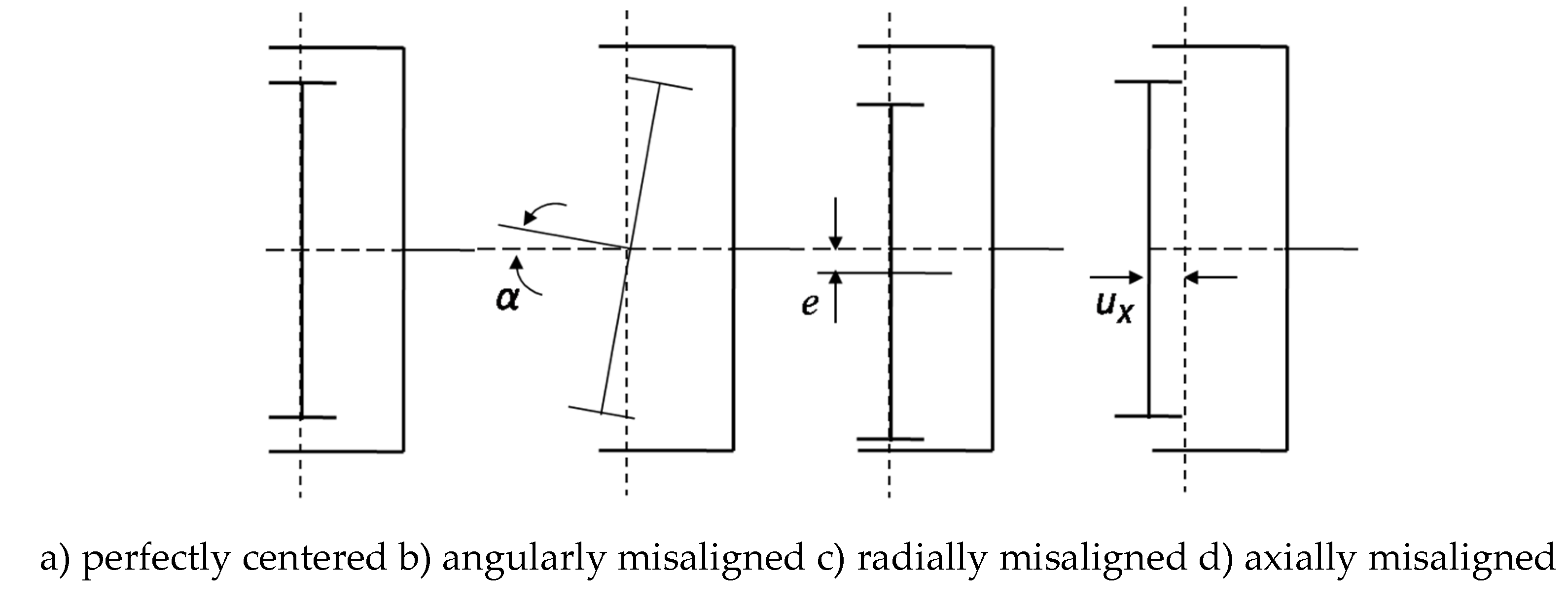
Figure 3.
Cartesian coordinate system for motorized load analysis of floating spline shafts.
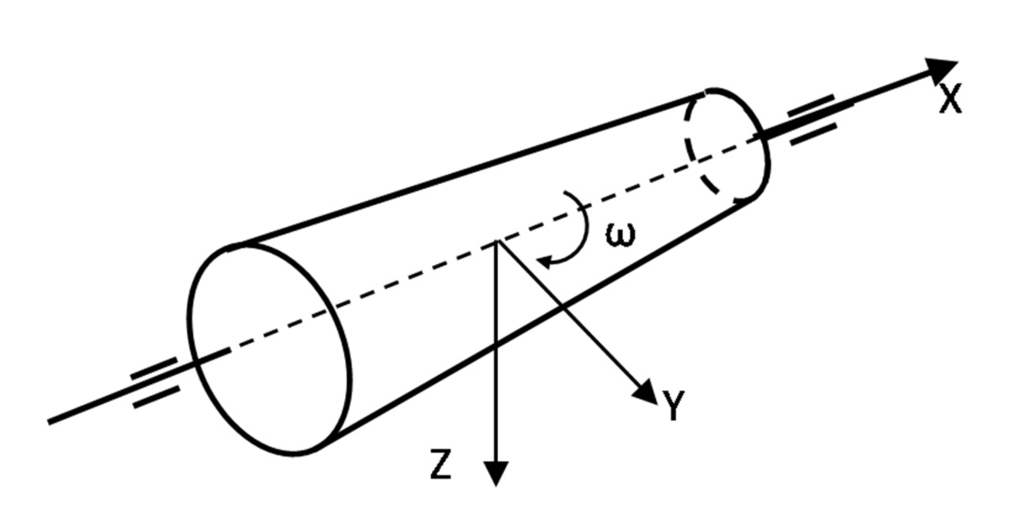
Figure 4.
Schematic diagram of floating spline shaft motorized loads.
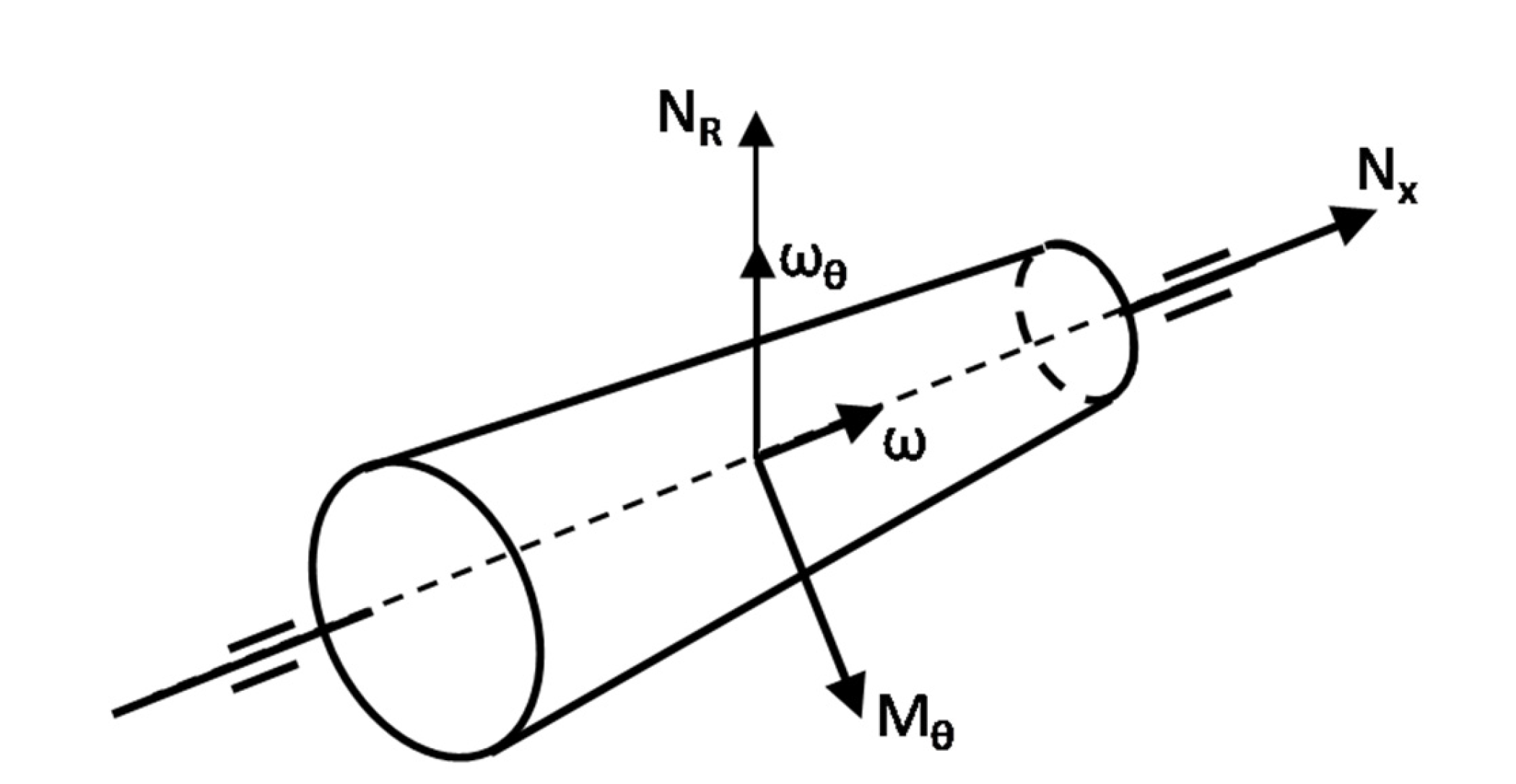
Figure 5.
Schematic diagram of a typical floating spline shaft structure for an aero-engine.
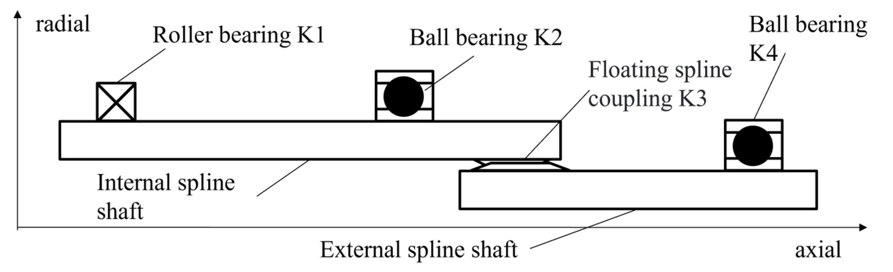
Figure 6.
Mechanical model for deformation analysis of spline maneuvering.
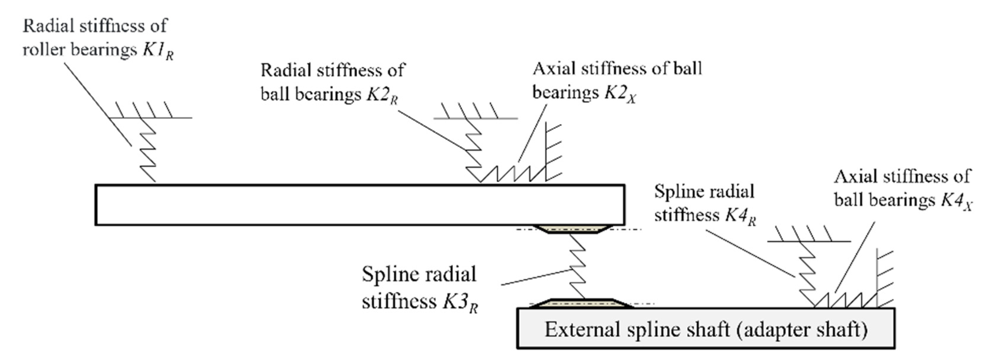
Figure 7.
Mechanical model for calculating spline meshing support stiffness.
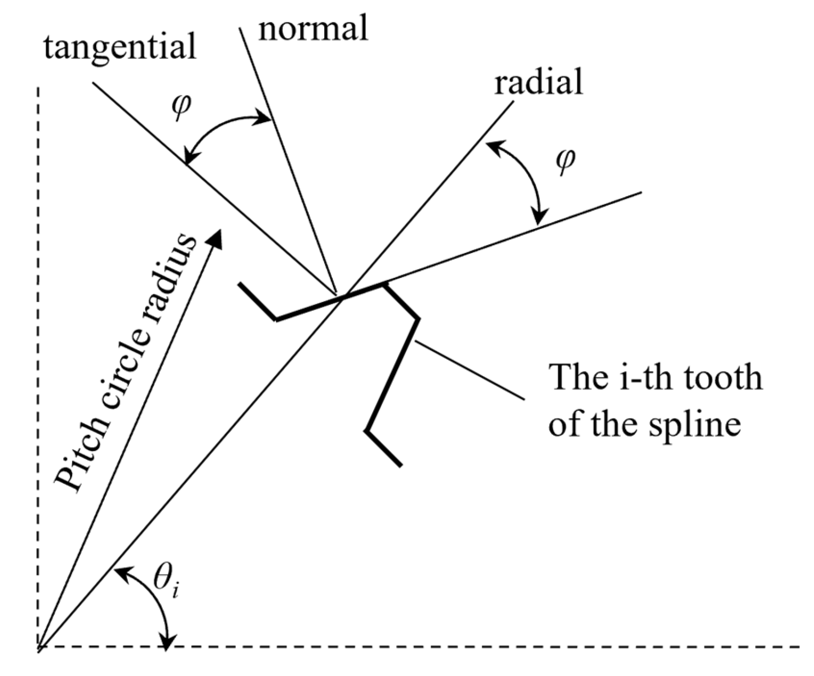
Figure 8.
Finite element model of floating involute spline maneuvering deformation for a certain type of engine.
Figure 8.
Finite element model of floating involute spline maneuvering deformation for a certain type of engine.
Figure 16.
Schematic diagram of loading and constraints for the finite element model of the floating spline.
Figure 16.
Schematic diagram of loading and constraints for the finite element model of the floating spline.
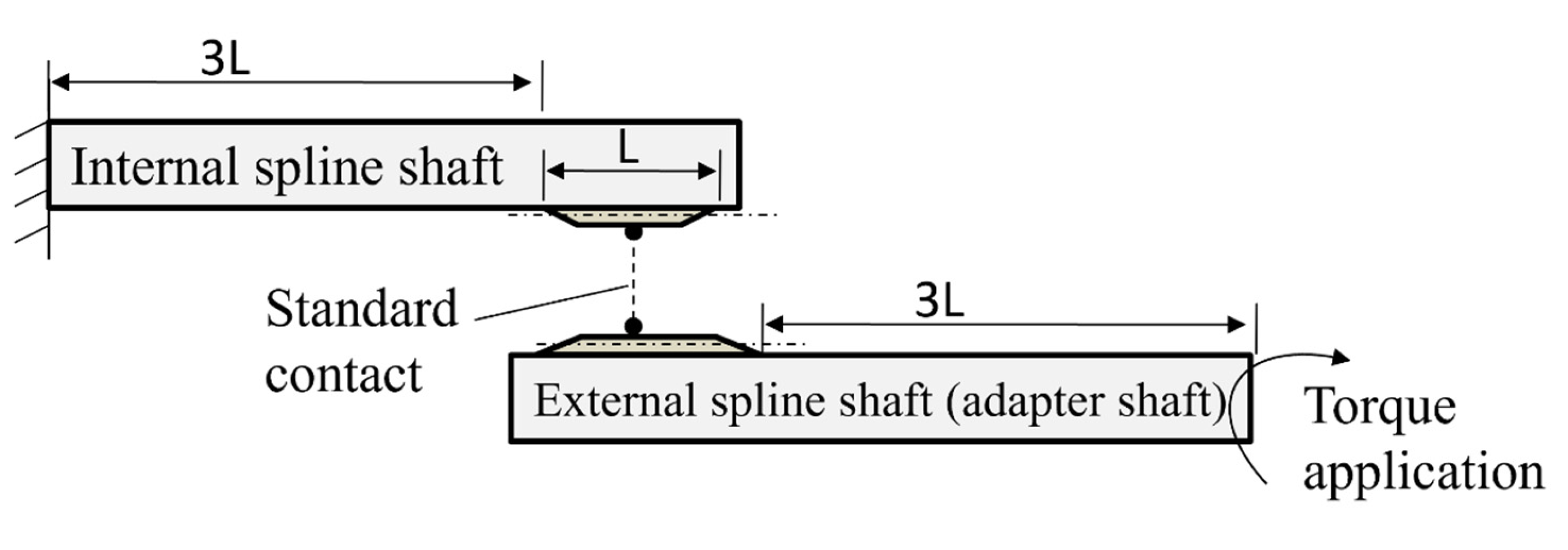
Figure 17.
External spline model with rounding and chamfering and mesh refinement.
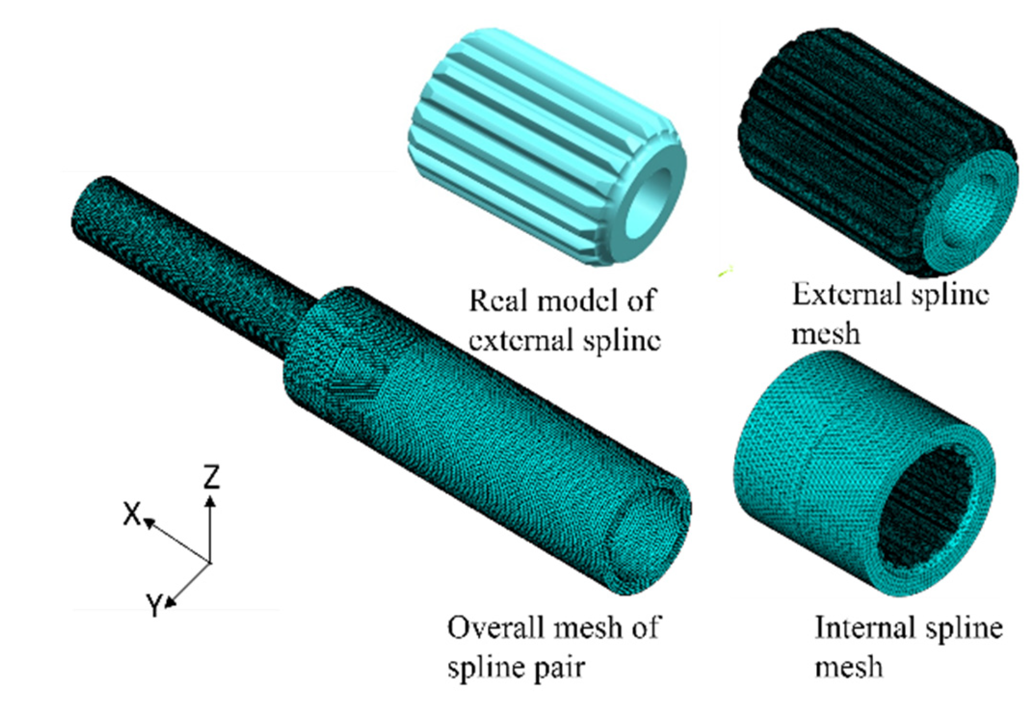
Figure 18.
External spline tooth numbering.
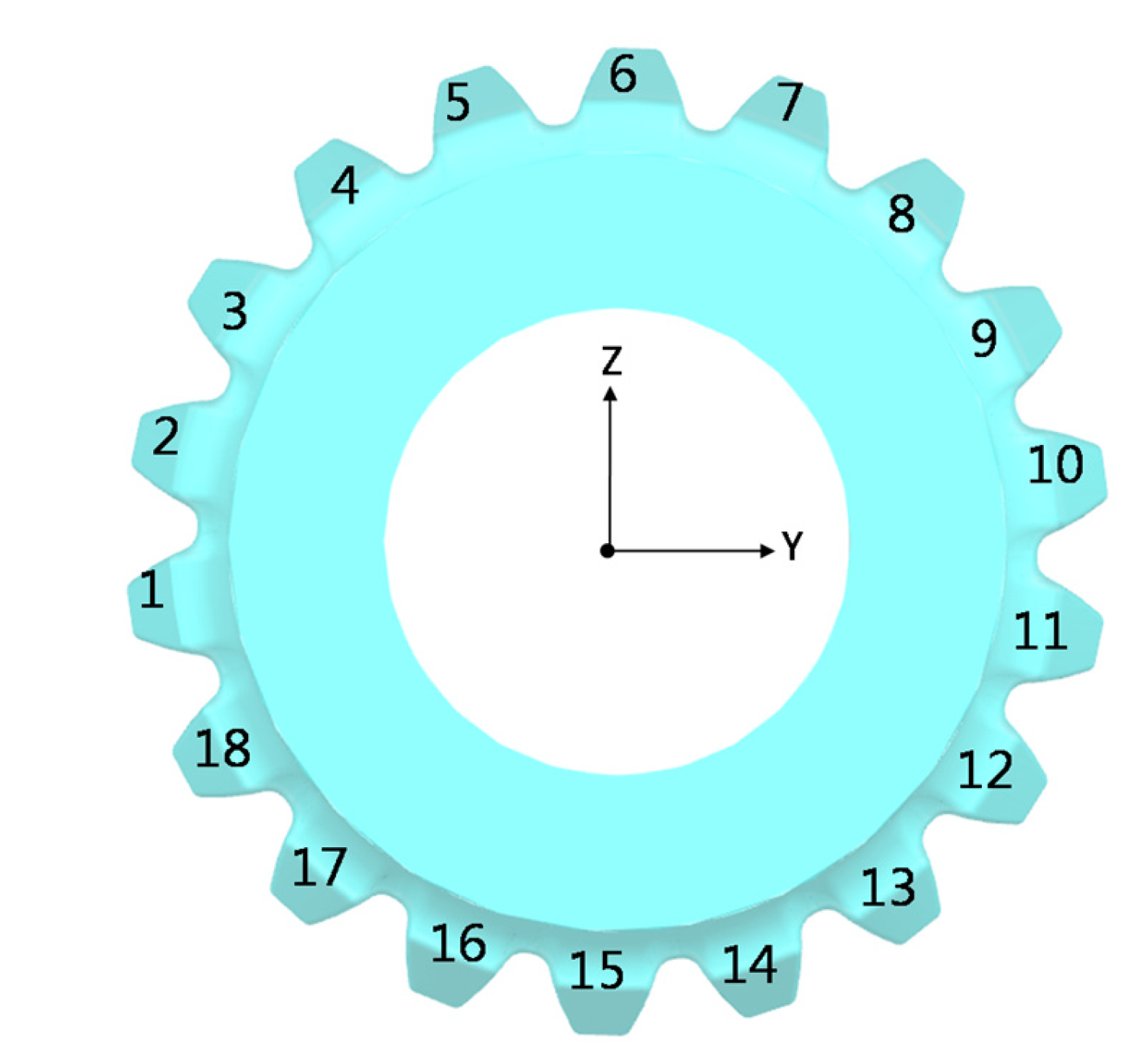
Figure 19.
Cloud diagram of contact pressure on the tooth surface of each tooth of the external spline under ultimate load 2.
Figure 19.
Cloud diagram of contact pressure on the tooth surface of each tooth of the external spline under ultimate load 2.
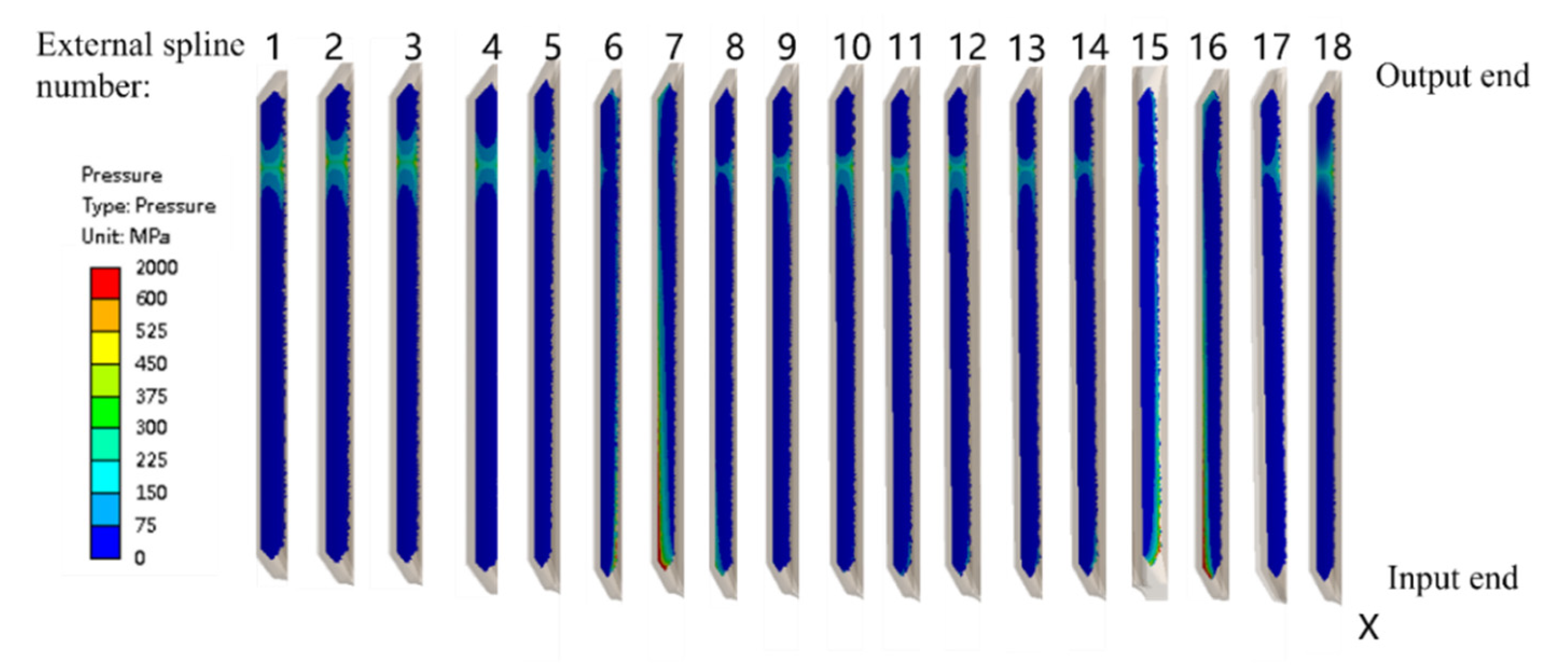
Figure 20.
Computation result of each tooth of the external spline under ultimate load 2.
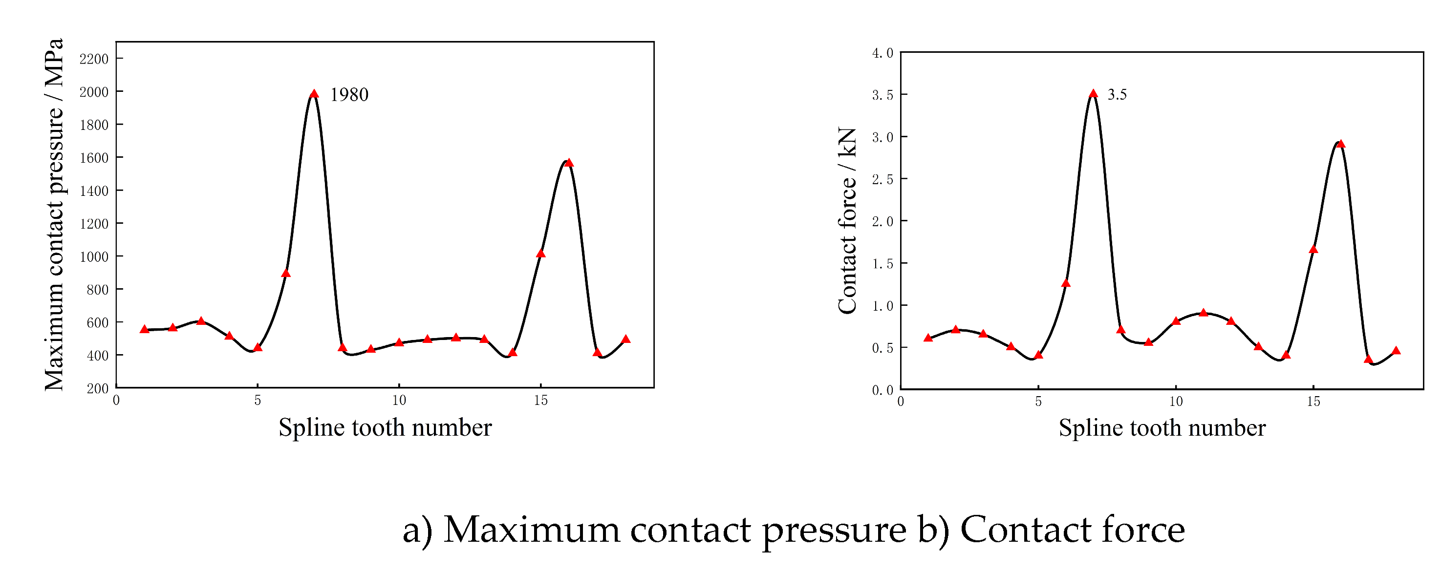
Figure 21.
Cloud diagram of tooth surface contact pressure of each tooth of external spline under limited load 2.
Figure 21.
Cloud diagram of tooth surface contact pressure of each tooth of external spline under limited load 2.
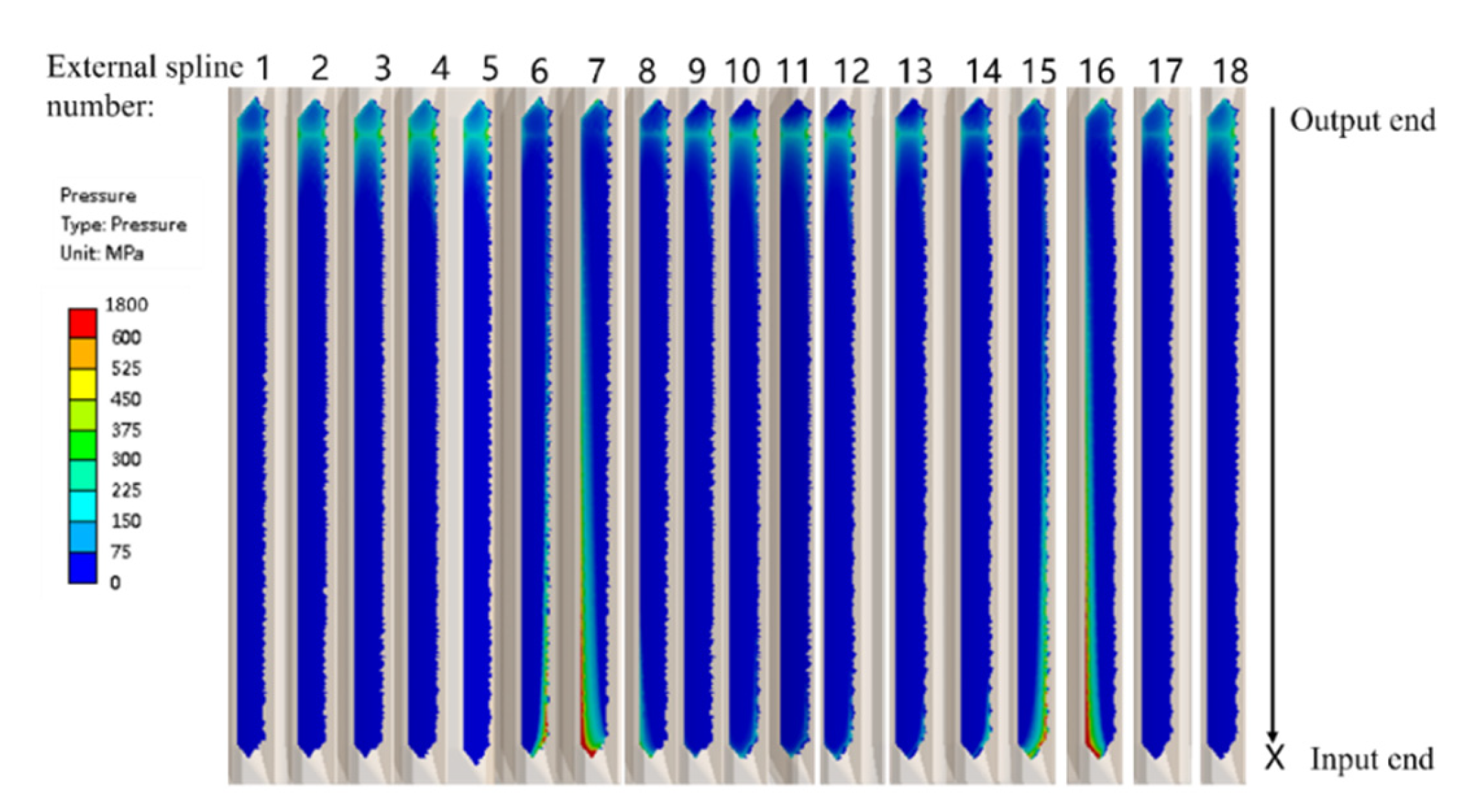
Figure 22.
Computation result of each tooth of external spline under limited load 2.
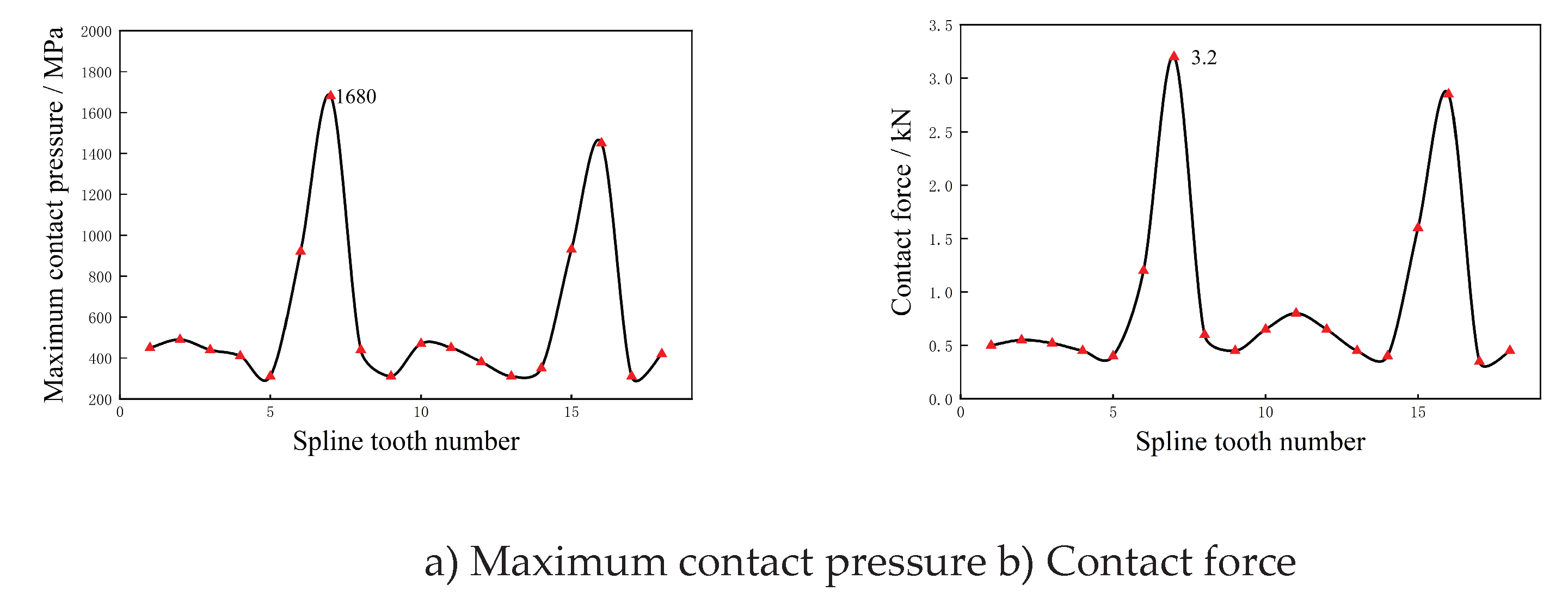
Table 1.
Types and symbols of misalignment of floating spline pair.
| Types of spline misalignment | Symbol |
|---|---|
| Axial misalignment / mm | |
| Parallel misalignment / mm | e |
| Angular misalignment / ° | α |
Table 2.
Overload types and symbols.
Table 4.
Selected values for floating spline unit motorized load.
| Type of dynamic load | Symbol | Numerical value |
|---|---|---|
| Axial overload factor/g | 1 | |
| Radial overload factor/g | 1 | |
| Angular velocity of gyroscopic moment / (rad/s) | 1 | |
| Spin angular velocity / (rad/s) | ω | Ω |
Table 5.
Support stiffness parameter table for input in dynamic deformation analysis of spline shaft.
Table 5.
Support stiffness parameter table for input in dynamic deformation analysis of spline shaft.
| Parameter name | Parameter symbol |
|---|---|
| Radial support stiffness of the splined shaft roller bearing | K1R |
| Radial support stiffness of internal spline shaft ball bearing | K2R |
| Axial support stiffness of internal spline shaft ball bearing | K2X |
| Radial support stiffness of spline connection | K3R |
| Radial support stiffness of external spline shaft ball bearing | K4R |
| Axial support stiffness of external spline shaft ball bearing | K4X |
Table 6.
Table of Support Stiffness Parameters Input for Dynamic Deformation Analysis of Spline Shaft.
Table 6.
Table of Support Stiffness Parameters Input for Dynamic Deformation Analysis of Spline Shaft.
| Parameter name | Parameter symbol | Numerical value /(N/mm) |
| Radial support stiffness of the splined shaft roller bearing | K1R | 1.5κ |
| Radial support stiffness of internal spline shaft ball bearing | K2R | κ |
| Axial support stiffness of internal spline shaft ball bearing | K2X | κ |
| Radial support stiffness of spline connection | K3R | 35κ |
| Radial support stiffness of external spline shaft ball bearing | K4R | κ |
| Axial support stiffness of external spline shaft ball bearing | K4X | κ |
Table 7.
Structural parameters of involute floating splines.
Table 8.
Involute Floating Spline Material Parameters.
Table 11.
Calculation results of floating spline misalignment under the superposition of the most dangerous dynamic overload.
Table 11.
Calculation results of floating spline misalignment under the superposition of the most dangerous dynamic overload.
Table 13.
Evaluation Results of Contact Stress of Floating Spline Pair.
| Working scenario | Contact stress/MPa | Contact fatigue limit/MPa | Check result | Remarks |
| Limited load 2 | 1680 | 1470 | , Not satisfied | =0.9 |
| Ultimate load 2 | 1980 | 1470 | ,Satisfied | =1.6,=1.0 |
Disclaimer/Publisher’s Note: The statements, opinions and data contained in all publications are solely those of the individual author(s) and contributor(s) and not of MDPI and/or the editor(s). MDPI and/or the editor(s) disclaim responsibility for any injury to people or property resulting from any ideas, methods, instructions or products referred to in the content. |
© 2026 by the authors. Licensee MDPI, Basel, Switzerland. This article is an open access article distributed under the terms and conditions of the Creative Commons Attribution (CC BY) license.
Copyright: This open access article is published under a Creative Commons CC BY 4.0 license, which permit the free download, distribution, and reuse, provided that the author and preprint are cited in any reuse.


