
Submitted:
26 January 2026
Posted:
27 January 2026
You are already at the latest version
Abstract
As the digitalization of construction standards accelerates, the integration of structural analysis results into Building Information Modeling (BIM) environments has become a critical prerequisite for effective BIM-based Automated Code Checking (ACC), particularly for structural code compliance. In current practice, structural analysis results generated by Computer-Aided Engineering (CAE) tools are often manually transferred into IFC-based BIM models, leading to inefficiencies and increased risk of human error. To address this limitation, this study proposes an extended IFC-based representation, termed IFC-KR-Structure, designed to systematically organize and manage section-wise and load combination–dependent structural analysis results required for code compliance within the IFC environment. Based on the proposed schema, an automated CAE-to-BIM integration module was implemented within the IFC-KR Toolkit to enable direct integration of analysis results generated by a commercial CAE tool (midas Civil NX) into IFC models. The approach establishes consistent element correspondence between structural and BIM models through coordinate alignment and spatial mapping procedures and represents multidimensional analysis results using a schema-compliant, tabular data structure embedded within IFC models. The applicability of the proposed framework was validated using a prestressed concrete girder bridge case, confirming that structural analysis results were accurately mapped, stored, visualized, and subsequently utilized within a BIM-based ACC workflow. The results demonstrate that the proposed approach enables systematic reintegration of CAE-generated analysis results into BIM models and significantly improves the efficiency, consistency, and reliability of BIM-based code compliance processes.
Keywords:
Building Information Modeling (BIM)
; Industry Foundation Classes (IFC)
; structural analysis result integration
; BIM–CAE interoperability
; Automated Code Checking (ACC)
; IFC schema extension
1. Introduction
The construction industry is undergoing rapid digital transformation to improve the efficiency, consistency, and transparency of design and regulatory processes. In this context, construction standards—formal technical rules specifying safety, performance, and quality requirements for planning, design, and construction—are increasingly being digitalized, leading to growing interest in Building Information Modeling (BIM)–based Automated Code Checking (ACC). In Korea, this direction has been institutionalized through the Smart Construction Promotion Strategy (S-Construction 2030), announced in 2022, which promotes both the digitalization of construction standards and the establishment of BIM-based ACC environments [1].
BIM-based ACC requires the formalization of two complementary aspects. First, design workflows must be structured so that relevant standards and specifications can be associated with specific elements and project stages, enabling systematic identification of applicable checking items. Second, individual BIM elements must contain the properties and attribute values required to evaluate code requirements. Both aspects can be supported through extensions of the Industry Foundation Classes (IFC) schema that embed regulatory information within BIM models. Accordingly, several IFC-based extension approaches have been proposed to support the integration of construction standards into BIM environments. A representative example is IFC-KR, an extended IFC schema developed to encapsulate the requirements and properties of the Korean Design Standards (KDS) and Korean Construction Specifications (KCS) and to associate them directly with BIM elements [2,3]. Its practical application is supported by the IFC-KR Toolkit, which enables structured management of standards-related information within IFC-based environments. These approaches provide a solid foundation for linking regulatory requirements to BIM elements and organizing code-related attributes.
Despite these advances, a critical limitation remains in current BIM-based ACC workflows for structural compliance. Many structural code provisions rely directly on numerical structural analysis results—such as axial forces, shear forces, bending moments, and torsional moments—evaluated at specific section locations under multiple load combinations. These results are generated by external Computer-Aided Engineering (CAE) tools (e.g., SAP2000, midas Civil) and are not natively produced or managed within BIM environments. In current practice, verified analysis results are therefore manually transferred from CAE tools into BIM-based ACC systems. This process is inefficient and error-prone, particularly because structural analysis data are repetitive and multidimensional, varying by element, section location, and load combination.
This limitation is further compounded by the representational constraints of the IFC schema. Although IFC 4.3 provides structural entities such as IfcStructuralLoad and IfcStructuralActivity, these entities are primarily intended to describe load definitions and conceptual structural behavior rather than detailed numerical analysis results required for code compliance checking. Previous studies have reported that native IFC structural entities are insufficient for systematically representing section-wise and load combination-dependent analysis outputs generated by practical CAE tools [4,5,6]. As a result, existing IFC-based ACC environments lack a robust mechanism for consistently storing and managing structural analysis data in a form directly usable for compliance evaluation [7,8].
From the perspective of BIM-based ACC, this gap reflects a fundamental limitation of conventional BIM–CAE interoperability. In typical structural engineering workflows, BIM models primarily serve as sources of geometric and semantic information for generating simplified structural models in CAE tools. Information therefore flows predominantly from BIM to CAE, supporting efficient model generation and analysis execution. However, BIM-based ACC requires a complementary information flow in the opposite direction: verified structural analysis results produced in CAE environments must be systematically reintegrated into BIM models at the element level, where regulatory information and checking logic are managed.
To address this gap, this study proposes an extended IFC-based representation and integration approach tailored specifically to BIM-based ACC. First, an extended schema, termed IFC-KR-Structure, is developed to selectively organize and manage structural analysis results required for code compliance within the IFC environment. Second, a structured CAE-to-BIM integration methodology and an automated integration module are implemented to support the reliable insertion of verified analysis results into IFC models. Unlike conventional BIM–CAE interoperability approaches that focus primarily on model generation, the proposed approach explicitly targets the systematic reintegration of analysis results in a schema-compliant and ACC-oriented manner.
The scope of this study is limited to prestressed concrete (PSC) girder bridges and to structural compliance–related code checking items defined in the KDS. The proposed approach is validated using a real bridge BIM model, demonstrating that structural analysis results can be accurately mapped, consistently stored, and effectively utilized within the IFC environment.
The remainder of this paper is organized as follows. Section 2 reviews related work on BIM-based ACC, BIM–CAE interoperability, and IFC-based integration approaches. Section 3 presents the research methodology. Section 4 describes the development of the proposed IFC-KR-Structure and the CAE-to-BIM integration module. Section 5 reports the validation and demonstration results, and Section 6 discusses the implications and limitations of the proposed approach.
2. Research Background
2.1. BIM-Based Automated Code Checking and Its Limitations for Structural Code Compliance
BIM-based ACC has been widely studied as a means to improve the efficiency, consistency, and transparency of regulatory compliance in digital design environments. Numerous studies have demonstrated the feasibility of ACC in the building domain, particularly for checking tasks that can be evaluated directly from geometric information and static element properties, such as spatial clearance, accessibility, fire compartmentation, and energy performance [9,10].
However, the applicability of existing ACC approaches to structural code compliance remains fundamentally limited. Structural design standards, especially in the bridge domain, define requirements that depend not only on geometry and material properties but also on numerical structural analysis results, such as internal forces and moments evaluated at specific section locations under multiple load combinations. These results are inherently multidimensional and context-dependent, varying by element, section, and loading scenario.
Unlike many building-oriented ACC applications—where compliance can often be assessed using attributes already embedded in BIM models—structural design code compliance requires the integration of verified outputs from external CAE tools. Without systematic access to these analysis results within the BIM environment, ACC for structural code compliance cannot progress beyond partial or conceptual automation.
Accordingly, while prior research has established the general feasibility of BIM-based ACC, its extension to structural code compliance in infrastructure domains such as bridges requires explicit consideration of how CAE-generated analysis results can be systematically represented, managed, and reused within BIM environments. This gap forms a central motivation for the present study.
2.2. BIM–CAE Interoperability and Its Limitations for ACC
2.2.1. Predominance of Forward-Oriented BIM-to-CAE Workflows
Interoperability between BIM environments and structural analysis tools has been widely investigated, with most prior research focusing on forward-oriented BIM-to-CAE workflows. In these approaches, BIM models are transformed into simplified CAE models to support numerical analysis. Representative studies have proposed methods for interpreting IFC models or native BIM authoring models to automatically generate structural analysis models, thereby reducing redundant modeling efforts and improving efficiency [11,12].
Subsequent research further advanced BIM-to-CAE interoperability by proposing algorithmic techniques for converting BIM data into formats compatible with commercial CAE tools such as SAP2000, Robot, and Abaqus. These studies addressed technical challenges including geometric simplification, connectivity interpretation, and topology consistency to improve the reliability of automated CAE model generation [13,14,15]. More recently, [16] proposed an openBIM-based framework for automatically generating CAE models from architectural IFC models, illustrating a typical example of forward-oriented interoperability.
While these studies significantly improved the automation and reliability of CAE model generation and analysis execution, their primary objective remains the efficient transfer of design information from BIM to CAE, rather than the reuse of verified analysis results within BIM environments.
2.2.2. Need for Reverse CAE-to-BIM Integration for ACC
From the perspective of BIM-based ACC for structural code compliance, the limitations of conventional BIM–CAE interoperability become evident. ACC workflows require that verified structural analysis results—generated and validated within CAE environments—be available within BIM models, where regulatory information, element semantics, and checking logic are managed.
However, most existing BIM–CAE interoperability studies focus on improving model exchange and synchronization during the design and analysis process, such as through bidirectional conversion and round-tripping mechanisms to maintain consistency between architectural and structural models [17]. Although such approaches contribute to model-level consistency, they do not explicitly address the structured and automated reintegration of section-wise, load combination–dependent analysis results into IFC-based BIM models for the purpose of code compliance checking.
As a result, in practical workflows, verified analysis results remain largely confined within CAE environments and are typically transferred to BIM-based ACC systems through manual input. This creates inefficiencies and introduces the risk of inconsistency and human error, particularly for bridge projects where the volume of analysis data is substantial and multidimensional.
Accordingly, while BIM–CAE interoperability research has matured in the direction of BIM-to-CAE automation and model synchronization, a clear methodological gap remains in establishing a structured, reliable, and automated CAE-to-BIM integration approach specifically aimed at supporting BIM-based ACC for structural code compliance. Addressing this gap constitutes a core motivation for the present study.
2.3. Limitations of IFC for Representing Structural Analysis Results
2.3.1. Limitations of Native IFC Structural Entities
The IFC schema provides several entities related to structural modeling, such as IfcStructuralLoad and IfcStructuralActivity, which are primarily intended to represent analysis inputs and conceptual structural behavior [18]. However, multiple studies have reported that these entities are not suitable for representing detailed numerical analysis results required for structural code compliance, such as section-wise internal forces under multiple load combinations.
[4] identified a mismatch between the data structures supported by IFC and the information required by structural analysis tools, particularly for infrastructure applications. [19] similarly noted that early IFC structural extensions emphasized model configuration rather than result representation. More recently, [5] demonstrated that section-wise and load combination–dependent results cannot be systematically accommodated using native IFC structural entities, while [6] highlighted ongoing practical limitations in preserving engineering semantics across BIM–CAE exchanges.
Together, these studies indicate that the key limitation lies not only in tool interoperability but in the lack of an IFC-compatible data structure for organizing repetitive and multidimensional analysis results.
2.3.2. Limitations of Existing IFC Extension Approaches
IFC supports extensibility through Property Set (Pset)–based mechanisms, allowing domain-specific attributes to be added without modifying the core schema [20]. While several studies have explored Pset-based extensions for representing engineering information [21], these approaches are typically conceptual or manually defined and do not support the systematic management or automated population of large volumes of section-wise and load combination–dependent analysis results.
As a result, despite the theoretical extensibility of IFC, a practical and scalable method for representing and automatically integrating CAE-generated structural analysis results into IFC models remains largely unaddressed. This limitation poses a fundamental barrier to BIM-based ACC for structural code compliance and motivates the approach proposed in this study.
2.4. Existing Extension and Integration Approaches
2.4.1. Targeted Data Integration: Comparison with BCA XMI Framework
An approach closely related to the objective of this study is the Cross Model Information (XMI) framework proposed by the Building and Construction Authority (BCA) of Singapore as part of the CORENET-X initiative [22]. XMI defines a standardized schema for embedding structural analysis results within IFC models and supports automated data exchange between CAE tools (e.g., Bentley STAAD.Pro) and BIM authoring tools, as illustrated in Figure 1.
The XMI framework represents a significant step toward eliminating manual transfer of structural analysis data and demonstrates the feasibility of automated CAE–BIM synchronization. However, XMI adopts an inclusive data integration strategy, in which a broad range of analysis results are persistently embedded into IFC models. While this approach is suitable for comprehensive synchronization, it may lead to increased model size and reduced data-handling efficiency, particularly when many results are not directly required for downstream tasks such as ACC.
In contrast, BIM-based ACC requires only a limited subset of analysis results—those explicitly referenced by code provisions and evaluated at specific section locations under governing load combinations. This distinction highlights the need for a purpose-oriented and lightweight integration strategy, where only analysis data relevant to code compliance are selectively structured and stored. The present study adopts this targeted perspective while benchmarking the automation concept demonstrated by the XMI framework.
2.4.2. IFC-KR and Practical ACC Environments
To support practical BIM-based ACC in Korea, the IFC-KR schema was developed as an extension of IFC 4.3 to formally represent KDS and KCS within IFC-based BIM models [2]. IFC-KR addresses limitations of native IFC in representing construction standards–specific element distinctions, which are essential for accurate code compliance checking.
Although IFC 4.3 provides general-purpose entities such as IfcBridge, IfcBridgePart, and IfcBeam, it does not define many element types explicitly distinguished in construction standards. To resolve this, IFC-KR introduces standards-oriented classifications using USERDEFINED types. For example, in PSC girder bridges, structural compositions such as SUPERSTRUCTURE and SUBSTRUCTURE—explicitly defined in KDS but not provided as predefined types in IFC—are represented as USERDEFINED values within IfcBridgePart. Similarly, functional roles such as STIFFENING_GIRDER, which constitute distinct elements subject to specific code provisions in KDS, are explicitly defined as USERDEFINED types within IfcElementType. Through this approach, IFC-KR enables systematic linkage between BIM elements and relevant standards without modifying the core IFC schema (Figure 2).
Building on IFC-KR, the IFC-KR Toolkit was developed to support practical management of standards information within IFC models [23]. However, in its current form, the Toolkit primarily supports the management of regulatory information and design attributes. Structural analysis results generated by external CAE tools are not automatically integrated and must be entered manually. Given that such results are repetitive and multidimensional—varying by element, section location, and load combination—manual input significantly limits scalability in bridge projects.
Accordingly, while IFC-KR provides a strong foundation for representing regulatory semantics, a critical gap remains in the automated integration of CAE-generated structural analysis results. The present study directly addresses this gap by extending the IFC-KR framework with a dedicated representation structure for analysis results and by implementing an automated CAE-to-BIM integration module within the IFC-KR Toolkit.
3. Research Methodology
This study aims to establish a practical methodology for integrating verified structural analysis results generated in a CAE environment into IFC-based BIM models to support BIM-based ACC in the bridge domain. The core objective is not to automate BIM-to-CAE model generation, but to address the inverse and practically critical problem: systematically associating CAE-generated results with BIM elements and representing them within IFC models in a structured, reusable form.
The scope of the study is limited to PSC girder bridges designed in accordance with the KDS, reflecting common bridge engineering practice. Structural analysis is performed using midas Civil NX, a commercial CAE tool widely adopted in bridge design practice. The structural response variables considered in this study are limited to those explicitly required for KDS-based structural code compliance checks—namely axial force, shear force, bending moment, and torsional moment.
To support BIM-based ACC rather than general-purpose numerical post-processing, the scope of data integration is intentionally constrained. For each structural element (e.g., girders, copings, columns, and pier foundations), analysis results are considered only at five standardized section locations along the local element axis (I, 1/4, 2/4, 3/4, J) and for a limited number of governing load combinations. This reflects typical engineering practice in bridge design and code checking and ensures that the resulting dataset remains compact and interpretable for ACC purposes.
A key challenge addressed in this study is the lack of a systematic mechanism for associating CAE-generated results with corresponding elements in IFC-based BIM models. In practice, direct reuse of analysis results is hindered by differences between CAE and BIM models, including coordinate systems, element segmentation, and variable naming conventions. Accordingly, this study proposes a structured CAE-to-BIM integration methodology that enables reliable element-wise association and consistent representation of structural analysis results within IFC models.
To realize this objective, interoperability between the CAE environment and the IFC-based BIM environment is established using a Representational State Transfer (REST) API–based communication interface provided by midas Civil NX. This enables automated extraction of analysis results from the CAE environment and structured insertion into IFC models without manual file-based transfer. As illustrated in Figure 3, the overall research methodology consists of three main stages.
Stage 1: Definition of ACC-oriented information requirements and IFC representation strategy.
In the first stage, the scope of structural analysis information required for BIM-based ACC is defined based on KDS provisions and expert practice. This includes identifying target structural variables, section locations, and load combination requirements. Based on these requirements, an IFC-compatible representation strategy for storing analysis results within BIM models is established, leading to the design of the extended schema referred to as IFC-KR-Structure.
Stage 2: Development of CAE–BIM model alignment and mapping methodology.
In the second stage, methodological challenges arising from inconsistencies between CAE and BIM models are addressed. This includes the development of procedures for (i) extracting reference data from both models, (ii) performing coordinate alignment, (iii) establishing element-level correspondence between CAE and IFC elements, and (iv) resolving semantic differences through variable name mapping. Together, these procedures enable reliable association between analysis results and BIM elements.
Stage 3: Implementation of automated integration and validation.
In the third stage, the proposed schema and integration methodology are implemented as an automated integration module within the IFC-KR Toolkit. The module supports REST API–based extraction of CAE results, automated insertion into IFC models, and consistency checking of the integrated data. The effectiveness of the proposed approach is subsequently evaluated through quantitative validation and demonstration, as presented in Section 5.
4. Proposed Framework and System Development
4.1. Scope and Representation of the IFC-KR-Structure
This section defines the scope of structural analysis information to be integrated into BIM models for ACC and describes how this information is represented within the extended IFC-KR-Structure. The objective is not to comprehensively transfer all numerical results generated by CAE tools, but to selectively extract and structure only the information necessary for practical ACC execution in the context of girder bridge design.
4.1.1. KDS Evaluation Requirements and Structural Analysis Results in CAE Tools
To determine what information should be exported from the CAE environment to the BIM environment for practical ACC, this study did not rely solely on document-based interpretation of the KDS. Instead, the scope was defined based on expert interviews with practicing structural engineers from structural engineering firms and specialists from MIDAS (the developer of midas Civil NX), all with extensive experience in KDS-based bridge design and review. A total of 3 experts were consulted, each with more than 10 years of professional experience in bridge structural engineering.
The interviews confirmed that, in practical design and verification workflows PSC girder bridges, structural code compliance checks for the primary structural elements—such as main girders and other key superstructure components—are consistently based on four fundamental structural response quantities: axial force, shear force, bending moment, and torsional moment. These quantities are routinely examined by engineers and are directly referenced in the application of KDS provisions.
The experts further indicated that these checks are not performed continuously along the entire length of each element, but rather at a limited number of representative section locations that are widely accepted in practice. Accordingly, this study adopted five standard section locations along the local axis of each structural element—I-end, 1/4, 2/4, 3/4, and J-end—as the extraction points for structural analysis results.
Based on these expert-informed findings, the scope of data exported from the CAE environment was defined as:
- Structural response variables: axial force, shear force, bending moment, and torsional moment;
- Extraction locations: I-end, 1/4, 2/4, 3/4, and J-end of each element;
- Analysis conditions: a limited number of governing load combinations required for KDS-based structural code compliance checks.
As illustrated in Figure 4, each CAE element yields a discrete set of analysis results defined by structural response variables, extraction locations, and analysis conditions. This CAE element level data structure constitutes the basic information unit to be exported from the CAE environment and subsequently integrated into the IFC model.
Table 1 summarizes the structural analysis variables selected in this study and their relationships to representative KDS provisions, demonstrating that the selected variables are directly grounded in practical code-checking requirements rather than being arbitrarily chosen.
4.1.2. Selection of IFC Entities for Representing Structural Analysis Results
Once the scope of the required structural analysis information was defined, the next issue was how this information should be represented within the IFC environment in a structured, consistent, and reusable manner.
IFC provides an extensibility mechanism based on property sets (IfcPropertySet), which allows additional information to be attached to existing entities while preserving their original semantics. This mechanism is effective for representing individual properties or limited attribute sets. However, it becomes inadequate when applied to repetitive structural analysis results that vary simultaneously by section location and load combination [24]. Structural analysis results required for construction code compliance are inherently multidimensional datasets defined by element, section, and governing load combination, and therefore require a more structured representation mechanism.
Previous studies on IFC-based interoperability for structural analysis have also highlighted limitations of native IFC structural entities for this purpose. Entities such as IfcStructuralResultGroup were primarily intended to represent conceptual groupings of structural responses rather than detailed numerical results needed for design verification and code compliance checking [4,19]. Moreover, the practical use of IfcStructuralResultGroup remains limited due to inconsistent implementation and support across BIM tools, which restricts its applicability in real-world exchange environments.
An alternative strategy is to manage analysis results externally and reference them through entities such as IfcDocumentReference. While this approach can be advantageous for managing large datasets in terms of performance and scalability, it does not align with the objective of this study, which seeks to embed ACC-relevant analysis results directly within the internal data structure of IFC models to enable seamless use within BIM-based ACC workflows.
Based on these considerations, this study comparatively reviewed the IFC entities that support tabular data representation in IFC 4.3, namely IfcPropertyTableValue and IfcTable. Although IfcPropertyTableValue provides a structured representation, it is restricted to two-column tables and is therefore insufficient for expressing multidimensional datasets such as element–section–load combination–dependent analysis results. In contrast, IfcTable supports flexible definition of rows and columns, making it suitable for organizing repetitive structural analysis data in a systematic and interpretable format.
Figure 5 illustrates the conceptual mapping between structural analysis results generated in the CAE environment and their structured representation within the proposed IFC-KR-Structure. As shown in the figure, analysis results are associated with corresponding BIM elements and organized according to section locations and governing load combinations, providing a consistent internal data structure that supports downstream BIM-based ACC execution.
Accordingly, this study adopts IfcTable as the core entity within IFC-KR-Structure for representing section-wise and load combination–dependent structural analysis results, while remaining fully compatible with the IFC 4.3 schema and its extensibility principles [20].
4.2. CAE–BIM Model Alignment
Reliable integration of structural analysis results into IFC-based BIM models requires establishing consistent correspondence between the CAE model and the BIM model. In practice, these models are often developed independently and therefore differ in coordinate systems, geometric representations, and element segmentation. Without explicit alignment, such inconsistencies prevent accurate element-level association of analysis results.
Accordingly, this study defines a structured CAE–BIM model alignment methodology consisting of four sequential steps: (1) extraction of reference data, (2) coordinate alignment, (3) element mapping, and (4) variable name mapping. The PSC girder bridge case is used throughout this section solely as an illustrative example (Figure 6, Figure 7, Figure 8 and Figure 9).
4.2.1. Extraction of Reference Data
CAE models typically represent structures as node–element systems, whereas IFC-based BIM models represent elements as detailed solid geometries. Because of these differences, direct geometric comparison between the two models is not feasible.
To establish a common spatial basis, reference data are extracted from both models. From the CAE model, the coordinates of element start and end nodes are extracted as representative geometric descriptors. From the IFC model, the centerlines of structural elements are extracted to obtain a simplified linear representation compatible with the CAE model.
To define reference points for subsequent alignment, elements located at the minimum and maximum X-coordinates of the IFC model are identified. As illustrated in Figure 6, Ray-casting1 is applied to compute intersection points between the extracted centerlines and element surfaces, yielding two IFC reference points (IP1 and IP2). Corresponding reference points in the CAE model are defined using the nodes with minimum and maximum X-coordinates (SPmin,X and SPmax,X). These paired reference points form the basis for coordinate alignment.
4.2.2. Coordinate Alignment
Using the extracted reference points, the CAE model is transformed into the coordinate system of the IFC model through a sequence of rotation, scaling, and translation operations (Figure 7).
First, the angular difference between the reference vectors of the two models is computed, and the CAE model is rotated about the global Z-axis using the rotation matrix defined in Equation (1). The rotated node coordinates are then obtained using Equation (2).
Second, a scale factor is calculated as the ratio of distances between corresponding reference points (Equation (3)) and applied to the rotated coordinates (Equation (4)).
Finally, a translation vector is computed to align the scaled CAE reference point with the corresponding IFC reference point (Equation (5)), and the final transformed coordinates are obtained using Equation (6).
Through this transformation process, spatial discrepancies between the two models are eliminated, enabling consistent geometric comparison and reliable element-level correspondence.
4.2.3. Element Mapping
Once both models are expressed within a unified coordinate system, an element mapping procedure is performed to establish correspondence between CAE elements and IFC elements. Because element segmentation often differs between the two models, direct one-to-one matching based on element identifiers is not applicable.
A bounding box–based mapping strategy is therefore adopted (Figure 8). Bounding boxes are generated for IFC elements, and the start and end nodes of each CAE element are evaluated for spatial inclusion within these bounding boxes, producing a set of candidate IFC elements.
To resolve cases where a CAE element overlaps multiple IFC elements, an ‘inclusion ratio’ is computed for each candidate. The IFC element exhibiting the highest inclusion ratio is selected as the corresponding element.
For example, as illustrated in Figure 8, CAE element 3 (Elem 3) spans two adjacent IFC elements, namely IFC element 1 (GUID: LS123H8D) and IFC element 2 (GUID: 2LK3THG8). Due to differences in segmentation granularity, Elem3 is partially included in both IFC element bounding boxes, with 20% of its length contained in IFC element 1 and 80% in IFC element 2. Accordingly, Elem 3 is mapped to IFC element 2, which exhibits the higher inclusion ratio.
This example demonstrates that the proposed approach enables robust element-level correspondence despite segmentation differences between the two models.
4.2.4. Variable Name Mapping
To ensure semantic consistency between the CAE environment and the IFC-KR-Structure, a variable name mapping table is defined to establish one-to-one correspondence between analysis variable names used in midas Civil NX and those defined in IFC-KR-Structure. Although both systems represent identical physical quantities, differences in naming conventions necessitate a standardized reference for automated integration.
Only variables extractable through the midas Civil NX API are considered. Each variable is mapped based on physical quantity (axial force, shear force, bending moment, torsional moment), unit, section location (I, 1/4, 2/4, 3/4, J), and governing load combination. This mapping enables consistent interpretation of analysis results across environments.
Figure 9 presents an example of the variable name mapping table used in this study. By applying this mapping, data omission and misinterpretation caused by naming inconsistencies are prevented, thereby providing a reliable semantic foundation for automated result integration and downstream BIM-based ACC execution.
4.3. Development of a REST API–Based Structural Analysis Result Integration Module
This section describes the implementation of an automated integration module that operationalizes the methodology defined in Section 4.2. The module is designed to automatically insert verified structural analysis results generated in a CAE environment into IFC-based BIM models in accordance with the IFC-KR-Structure schema. Communication between midas Civil NX and the IFC-KR Toolkit is realized through a REST API–based interface.
In this study, the structural analysis model is developed directly within the CAE environment (midas Civil NX), reflecting common engineering practice. The proposed approach does not aim to automate BIM-to-CAE model generation, but instead focuses on the inverse problem: systematically integrating verified CAE-generated analysis results into IFC-based BIM models to support BIM-based ACC. This scope is intentional, as CAE modeling typically involves expert judgment in modeling assumptions and load combinations that cannot be reliably derived through fully automated conversion.
A REST API was adopted because it provides a lightweight, platform-independent, and widely supported mechanism for structured data exchange. In particular, it enables direct access to analysis results from commercial CAE software without file-based export/import, supports automation, and facilitates integration with external applications such as BIM-based toolkits. These characteristics are essential for implementing a practical and scalable CAE–BIM integration workflow.
The integration module operates through three functional stages: (1) retrieval of structural analysis results from midas Civil NX; (2) extension of detailed types and automated insertion of results; and (3) consistency check of the integrated results.
- (1)
- Retrieval of structural analysis results from midas Civil NX
Structural analysis is first performed on the target model using midas Civil NX. After analysis completion, the module establishes a REST API connection to retrieve the required analysis results directly from the CAE environment. This API-based approach enables automated data transfer without manual conversion, thereby reducing the risk of information loss and transcription errors.
- (2)
- Extension of detailed types and automated insertion of results
Within the IFC-KR Toolkit, target BIM elements are extended with predefined detailed types required for ACC. Relevant construction standard items are then associated with the corresponding elements, after which the module automatically inserts the retrieved analysis results into the IFC model in accordance with the IFC-KR-Structure schema.
As illustrated in Figure 10, this process is executed through the IFC-KR Toolkit interface, where users select target elements, extend applicable standard items, and trigger the automated insertion of structural analysis results.
- (3)
- Consistency check of integrated structural analysis results
After integration, the inserted results are stored within the IFC model and can be visualized and reviewed using the IFC-KR Toolkit. This enables users to perform a consistency check, confirming that analysis results are correctly associated with the appropriate elements and stored in the expected structure. The detailed validation procedures and quantitative evaluation of correctness and completeness are presented in Section 5.
5. Validation and Demonstration
This section evaluates the performance of the proposed CAE–BIM integration approach and demonstrates its practical usability in a downstream BIM-based ACC workflow. Validation focuses on whether structural analysis results generated in the CAE environment are (i) transferred to the IFC model without numerical distortion, (ii) stored completely without data loss, and (iii) correctly associated with their corresponding BIM elements. In addition, a short demonstration is provided to confirm that the extended IFC model can be consumed by an external ACC script.
The validation is structured into three complementary aspects—numerical correctness, completeness, and mapping consistency—because each addresses a distinct potential failure mode in CAE–BIM integration. Numerical correctness verifies that values are transferred without distortion. Completeness confirms that no required entries are lost during automated processing. Mapping consistency ensures that each analysis result is associated with the correct IFC element rather than an adjacent or unrelated object.
All three aspects were evaluated using a representative sampled dataset, as described in Section 5.1.1.
Together, these checks provide systematic evidence that the proposed integration reliably preserves both the quantitative integrity and the structural semantics of CAE-generated results within the IFC environment.
5.1. Validation of Integration Performance
5.1.1. Validation Setup
Validation was conducted using a PSC girder bridge case. Structural analysis results were generated in midas Civil NX and transferred to the IFC model using the proposed REST API–based integration module.
The automated integration process generated results for a total of 51 structural elements (45 girders, 2 copings, 2 columns, and 2 pier foundations), covering four structural response variables, five section locations, and eight governing load combinations.
For validation, a representative subset of 7 IFC elements was selected, consisting of 4 girders, 1 coping, 1 column, and 1 pier foundation. These elements were sampled across different locations of the bridge model to ensure coverage of both superstructure and substructure components. The selected IFC elements were mapped to a total of 30 CAE elements, and validation was conducted at the CAE element level, where structural analysis results are generated and transferred.
For each CAE element, the following data were evaluated:
- Structural response variables: axial force, shear force, bending moment, torsional moment (4 variables);
- Section locations: I, 1/4, 2/4, 3/4, J (5 locations);
- Governing load combinations: dead load, moving load, pavement load (3 representative combinations).
This resulted in a total of 1,800 data entries (i.e., 30 CAE elements × 4 variables × 5 section locations × 3 load combinations). These entries were manually cross-checked against the CAE outputs and the corresponding values stored in the IFC model.
This sampling-based validation strategy reflects a realistic and feasible verification approach, as exhaustive manual validation of all automatically generated entries for the entire IFC model—covering all integrated CAE elements, response variables, section locations, and governing load combinations (50,560 entries in total)—would not be practical. At the same time, the selected subset provides sufficient coverage to rigorously evaluate numerical correctness, completeness, and mapping consistency of the proposed CAE–IFC integration method.
5.1.2. Correctness of Transferred Values
To evaluate numerical correctness, each analysis value retrieved from midas Civil NX via the REST API was compared with the corresponding value stored in the extended IFC model after integration. For each entry, the absolute difference was computed (Table 2).
These results indicate that the proposed module transfers structural analysis results without numerical distortion and stores them correctly within the IFC model. To illustrate the integration at the element level, Table 3 presents a subset of validation results for one representative PSC girder element.
5.1.3. Completeness and Mapping Success
Completeness was evaluated by comparing the number of expected data entries with the number of entries actually recorded in the extended IFC model (Table 4).
As shown in Table 5, element mapping correctness was evaluated by confirming that each CAE element was associated with the intended IFC element according to the mapping procedure defined in Section 4.2. Element mapping performance was evaluated at the IFC element level. Therefore, the number of tested elements corresponds to the 7 IFC elements included in the validation model.
No missing entries were observed in this case study. In general, missing or mismatched entries may occur when (i) CAE–BIM element mapping becomes ambiguous due to segmentation inconsistencies, (ii) specific variables or load combinations are not available through the CAE API, or (iii) coordinate alignment tolerances cause nodes to fall outside IFC element bounds. The proposed workflow mitigates such cases through reference-point–based alignment and inclusion-ratio–based mapping, but these edge cases should be considered when applying the method to larger and more heterogeneous models.
5.2. Demonstration of Downstream ACC Usability
This section provides a demonstration to confirm that the extended IFC model generated through the proposed integration approach can be practically used in a downstream BIM-based ACC workflow. The objective is not to validate the correctness of the code interpretation itself, but to demonstrate that structural analysis results integrated into the IFC model can be successfully retrieved, combined with design information, processed by executable scripts, and written back into the IFC model.
As illustrated in Figure 11, the demonstration follows a three-stage workflow consisting of input, execution, and output stages, as reflected in the structure of Section 5.2.1, Section 5.2.2 and Section 5.2.3.
5.2.1. Input Stage: Demonstration Setup and Checking Logic
The input stage focuses on preparing executable data and logic for ACC. A representative KDS structural compliance provision—KDS 24 14 21 4.1.2.2 (2) (design shear strength of prestressed members without shear reinforcement considering flexural cracking)—was selected as a running example.
This provision requires evaluation of design shear strength using a formula that combines:
- Structural response values (e.g., axial force, shear force);
- Section properties (e.g., moment of inertia, cross-sectional area);
- Material and design parameters (e.g., concrete strength, material factors).
Two inputs were prepared in this stage:
- (1)
- Extended IFC model (data input)
The extended IFC model produced through the proposed CAE–IFC integration contains the structural analysis results stored in element-level Psets and the design and standards-related properties defined under IFC-KR.
- (2)
- Executable checking logic (rule input)
A Python-based ACC script was manually implemented based on the official KDS clause. This script represents the executable checking logic and defines which properties must be retrieved from the IFC model and how they are used in the calculation.
This stage confirms that the extended IFC model provides all necessary input data required for executable ACC.
5.2.2. Execution Stage: Variable Retrieval and Automated Calculation
The execution stage corresponds to the automated processing shown in the middle part of Figure 11. During execution, the ACC script performs the following operations:
- (1)
- Identifies the target element within the extended IFC model;
- (2)
- Retrieves the Pset associated with the selected KDS item;
- (3)
- Extracts all required variables (structural responses, section properties, and design parameters);
- (4)
- Executes the KDS-based calculation logic using the retrieved values.
Table 6 summarizes the variables required by the selected KDS provision and distinguishes which variables are supplied by the proposed CAE–IFC integration and which originate from BIM/design information.
This stage demonstrates that the structural response variables supplied by the proposed integration (CAE → IFC) can be directly consumed during automated computation, together with existing BIM/design properties.
5.2.3. Output Stage: Recording of ACC Results in IFC
The output stage corresponds to the final step in Figure 11, where checking results are written back into the IFC environment. After executing the checking logic, the script records the intermediate calculation results and the final pass/fail outcome directly into the Pset associated with the corresponding KDS item in the extended IFC model (Table 7).
The successful write-back of results confirms that the extended IFC model supports a closed-loop workflow of data input → automated processing → result recording, which is a fundamental requirement for practical BIM-based ACC environments.
6. Discussion
6.1. Implications of the Results
The proposed methodology has several important implications for BIM-based ACC and BIM–CAE interoperability. First, this study addresses a methodological gap in existing interoperability research by explicitly positioning CAE-to-BIM reintegration of verified analysis results as a core requirement for BIM-based ACC. Whereas most prior studies focus on forward-oriented BIM-to-CAE workflows for model generation and analysis execution, this study demonstrates that systematic reintegration of analysis results into BIM models is both feasible and necessary when BIM serves as the primary environment for regulatory evaluation.
Second, this study provides a technical contribution by demonstrating that repetitive and multidimensional structural analysis results—varying by element, section location, and load combination—can be represented within the IFC environment in a schema-compliant and interpretable manner. By structuring these results consistently and embedding them within IFC-based models, the proposed approach complements the limitations of native IFC structural entities and provides a reusable pattern for future studies addressing analysis result management in infrastructure-oriented BIM applications.
Third, from a practical perspective, the results suggest clear benefits for real-world engineering workflows. Automating the integration of analysis results eliminates the need for manual transcription of large volumes of repetitive data, thereby reducing the likelihood of human error and improving the efficiency and reliability of BIM-based ACC execution. This has particular significance for bridge projects, where the number of elements, checking locations, and governing load combinations can rapidly scale.
6.2. Limitations and Future Work
Despite these contributions, several limitations remain and point to directions for future research.
- (1)
-
Scalability of analysis data storage
- -
- In this study, analysis results were selectively limited to variables and conditions directly required for code compliance, resulting in compact datasets suitable for storage within IFC models. However, for applications involving significantly larger datasets—such as time-history results, dense result histories, or long-term monitoring data—embedding all numerical results directly within IFC files may raise concerns related to file size and data-handling efficiency.
- -
- Future research should therefore investigate hybrid strategies that preserve the ACC-oriented, structured representation proposed in this study while supporting scalable storage architectures, such as linked external repositories or distributed data services.
- (2)
-
Generalizability across infrastructure types
- -
- The proposed methodology was developed and validated using PSC girder bridges and KDS-based compliance items. While the underlying integration logic is not inherently limited to this bridge type, direct application to other structural systems (e.g., cable-stayed bridges, arch bridges) or other infrastructure domains (e.g., tunnels, railways) may require additional domain-specific consideration of relevant analysis variables, section definitions, and code requirements.
- -
- Future work should extend the framework incrementally by analyzing structural code compliance characteristics across a broader range of infrastructure facilities.
- (3)
-
Dependency on CAE-specific extraction mechanisms
- -
- The current implementation relies on the result extraction interface provided by a specific CAE tool. Although the overall integration architecture and IFC-based representation are tool-agnostic, practical deployment across heterogeneous engineering environments will require more generalized abstraction of result extraction processes.
- -
- Future studies should therefore explore standardized or intermediary extraction interfaces that decouple CAE-specific APIs from the IFC-based integration logic.
7. Conclusions
This study proposed an extended IFC-based approach to support BIM-based ACC by enabling the systematic integration of structural analysis results into IFC models. An extended schema, termed IFC-KR-Structure, was developed to represent section-wise and load combination–dependent analysis results in a manner compatible with the IFC extensibility framework. By adopting a multidimensional representation structure, the study demonstrated that analysis results required for code compliance can be embedded within IFC-based BIM environments without relying on external documents or manual transcription.
To support practical implementation, a structured CAE-to-BIM integration workflow was established to resolve key interoperability challenges between CAE models and IFC models, including differences in coordinate systems, element segmentation, and variable naming conventions. The workflow combines reference point–based coordinate alignment, bounding box–based element mapping, and standardized variable name mapping to enable reliable element-wise association between models. This methodology was implemented as an automated integration module within the IFC-KR Toolkit using a REST API–based connection to a commercial CAE tool.
Application to a real PSC girder bridge case confirmed that section-wise and load combination–dependent analysis results were correctly inserted, stored, and visualized within the IFC model and could be effectively utilized within a BIM-based ACC workflow. These results demonstrate that structural analysis data, which have traditionally been handled through manual and error-prone processes, can be systematically and automatically reintegrated into BIM models, thereby improving the efficiency, consistency, and reliability of structural compliance checking.
Nevertheless, the current implementation integrates analysis results for all predefined section locations in a batch-oriented manner, which may introduce redundant information for code provisions that require only specific sections. In addition, scalability considerations may arise when extending the approach to projects involving substantially larger datasets or a broader range of infrastructure types. Future research will therefore focus on (i) selectively integrating only ACC-critical analysis data required by individual code provisions and (ii) extending the proposed framework to support a wider range of infrastructure domains and heterogeneous CAE environments.
Author Contributions
Conceptualization, B.K.; Data Curation, Y.J., W.J. and S.P.; Formal Analysis, W.L., Y.J., W.J. and Y.Y.; Methodology, W.L. and B.K.; Software, W.L., Y.J. and W.J.; Supervision, B.K.; Validation, Y.Y., S.P. and B.K.; Visualization, W.L., Y.J. and W.J.; Writing—Original Draft, W.L. and Y.J.; Writing—Review and Editing, W.L., Y.Y. and B.K. All authors have read and agreed to the published version of the manuscript.
Funding
This research was supported by the Korea Agency for Infrastructure Technology Advancement (KAIA), funded by the Ministry of Land, Infrastructure, and Transport (RS-2020-KA156208).
Data Availability Statement
Data available on request due to restrictions.
Conflicts of Interest
The authors declare no conflicts of interest.
References
- Ministry of Land, Infrastructure and Transport (MOLIT). In the Future, Design Errors in Construction Projects will be Automatically Reviewed by Computers. https://www.molit.go.kr/USR/NEWS/m_71/dtl.jsp?lcmspage=1&id=95089150 (accessed on 11 Dec 2025).
- Suk, C.H.; Jeong, Y.J.; Jeon, H.I.; Yu, Y.S.; Koo, B.S.; Choi, B.H. Development of extended IFC schema for embedding construction standards in bridge. In Proceedings of the Korean Institute of Building Information Modeling Conference, Suwon, Korea, May 2024; pp. 76-77.
- Lee, W.; Kim, S.; Koo, B. Development of an automated process for integrating structural analysis information in the IFCs for BIM-based code compliance. In Proceedings of the KICEM Annual Conference 2024, Jeju, Korea, November 2024; pp. 321-322.
- Wan, C.; Chen, P.-H.; Tiong, R.L.K. Assessment of IFCs for structural analysis domain. ITcon. 2004, 9(5), pp. 75-95.
- Park, S. I., Lee, S. H., Almasi, A., & Song, J. H. Extended IFC-based strong form meshfree collocation analysis of a bridge structure. Autom. Constr. 2020, 119, 103364.
- Gerbino, S., Cieri, L., Rainieri, C., & Fabbrocino, G. On bim interoperability via the IFC standard: An assessment from the structural engineering and design viewpoint. Applied Sciences. 2021, 11(23), 11430.
- Dimyadi, J.; Amor, R. Automated building code compliance checking – Where is it at? Autom. Constr. 2013, 33, pp. 141-150.
- Bloch, T.; Sacks, R. Automating design review with artificial intelligence and BIM: State of the art and research framework. Autom. Constr. 2020, 113, 103136.
- Beach, T. H., Rezgui, Y., Li, H., & Kasim, T. (2015). A rule-based semantic approach for automated regulatory compliance in the construction sector. Expert Systems with Applications. 42(12), pp. 5219-5231.
- Solihin, W., Eastman, C., & Lee, Y.-C. (2017). Multiple representation approach to achieve high-performance spatial queries of 3D BIM data using a relational database. Autom. Constr. 81, pp. 369-388.
- Ramaji, I.J.; Memari, A.M. Interpretation of structural analytical models from the coordination view in building information models. Autom. Constr. 2018, 90, pp. 117-133.
- Sacks, R.; Eastman, C.; Lee, G.; Teicholz, P. Interoperability between BIM authoring tools and downstream analysis applications. In BIM Handbook: A Guide to Building Information Modeling for Owners, Designers, Engineers, Contractors, and Facility Managers, 3rd ed.; Wiley: Hoboken, NJ, USA, 2018; pp. 48-62.
- Bhusar, A. A., & Akhare, A. R. Application of BIM in structural engineering. SSRG International Journal of Civil Engineering, 2014, 1(5), pp. 12-20.
- Lai, H., & Deng, X. Interoperability analysis of IFC-based data exchange between heterogeneous BIM software. J. Civ. Eng. Manag. 2018, 24(7), pp. 537-555.
- Hamidavi, T.; Akula, M.; Messner, J. Automated generation of structural analysis models from BIM. J. Comput. Civ. Eng. 2020, 34.
- Singh, T., Mahmoodian, M., & Wang, S. Enhancing Open BIM Interoperability: Automated Generation of a Structural Model from an Architectural Model. Buildings (2075-5309). 2024, 14(8).
- Hu, Z.-Z.; Zhang, X.-Y.; Wang, H.-W.; Kassem, M. Improving interoperability between architectural and structural design models: An IFC-based approach with web-based tools. Autom. Constr. 2016, 66, pp. 29-42.
- Pazlar, T.; Turk, Ž. Interoperability in practice: Geometric data exchange using the IFC standard. ITcon. 2008, 13, pp. 362-380.
- Weise, M.; Katranuschkov, P.; Liebich, T.; Scherer, R.J. Structural Analysis Extension of the IFC Modelling Framework. ITcon 2003, 8, pp. 181-200.
- buildingSMART International (bSI). IFC 4.3 Documentation. buildingSMART International Documentation 2024.
- Jeong, Y.S.; Eastman, C.; Sacks, R.; Kaner, I. Benchmark tests for BIM data exchanges of precast concrete. Autom. Constr. 2009, 18.
- Building and Construction Authority (BCA). XMI-Schema. XMI-Schema Documentation 2023. Available online: https://www.xmi-schema.com (accessed on 20 Nov 2025).
- Suk, C. H., Jeong, Y. J., Yu, Y. S., Koo, B. S., Ryu, S. H. Development of Extended IFC Schema for BIM-based Korean Construction Standards Review. KIBIM Magazine. 2024, 14(2), pp. 35-48.
- Yu, Y.; Kim, S.; Jeon, H.; Koo, B. A systematic review of the trends and advances in IFC schema extensions for BIM interoperability. Appl. Sci. 2023, 13, 12560.
Figure 1.
Overview of the XMI–based CAE–BIM integration workflow proposed in the CORENET-X initiative.
Figure 1.
Overview of the XMI–based CAE–BIM integration workflow proposed in the CORENET-X initiative.
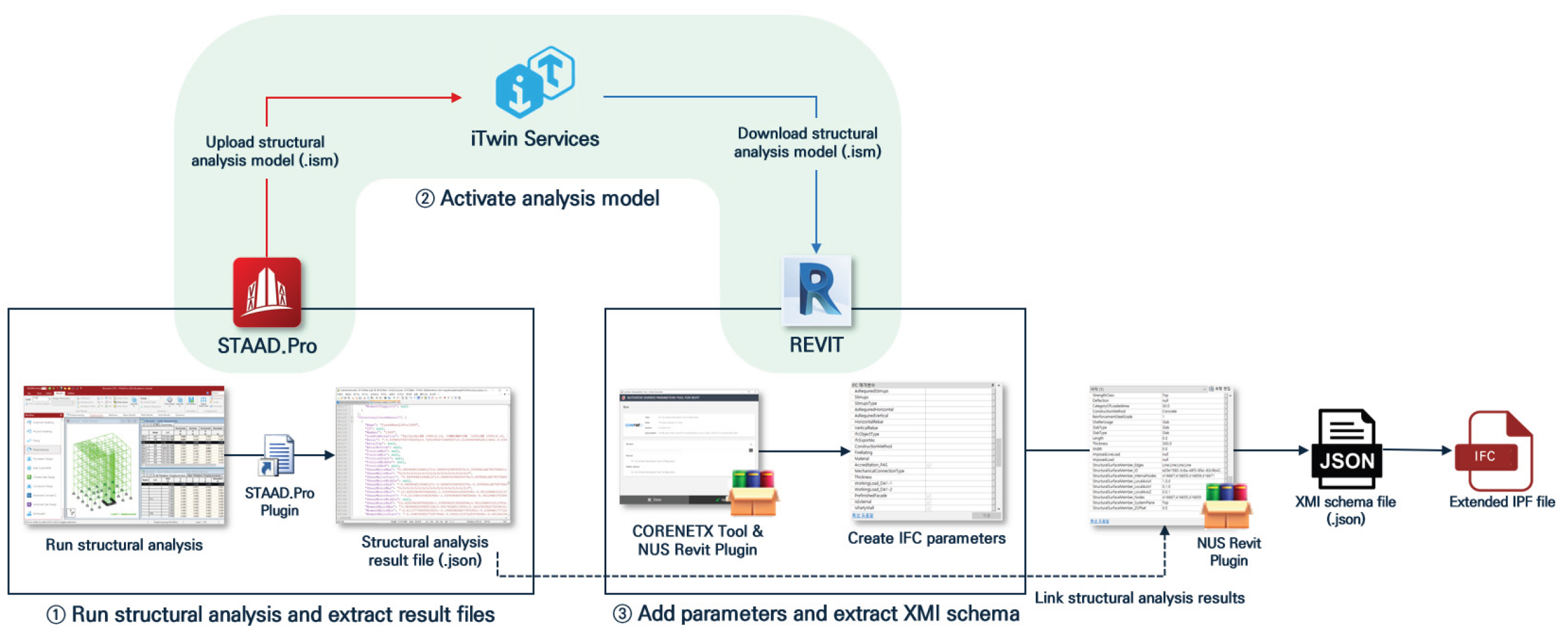
Figure 2.
Structure of the IFC-KR extension for representing construction standards–specific element types and properties in the bridge domain.
Figure 2.
Structure of the IFC-KR extension for representing construction standards–specific element types and properties in the bridge domain.
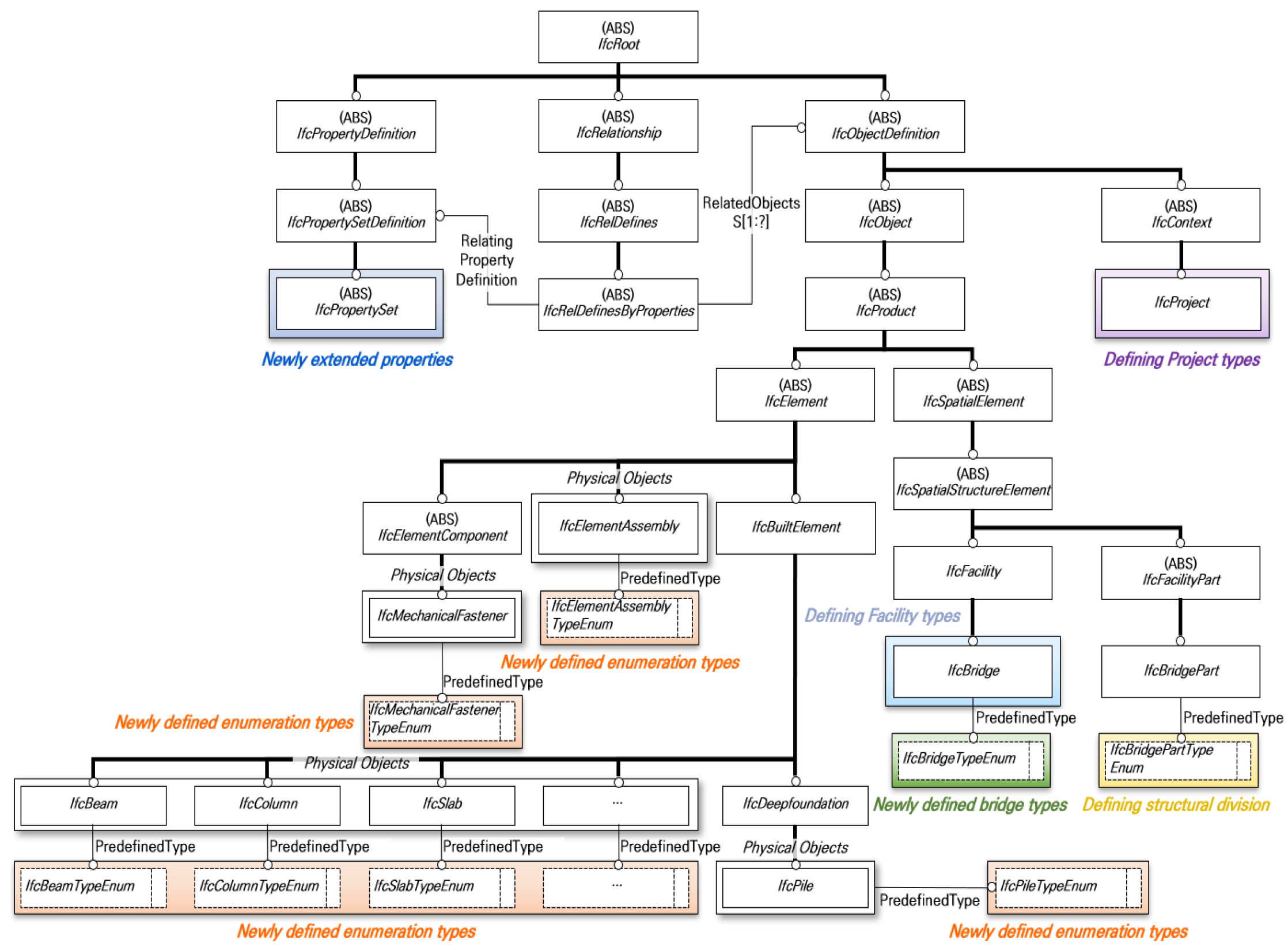
Figure 3.
Research methodology.
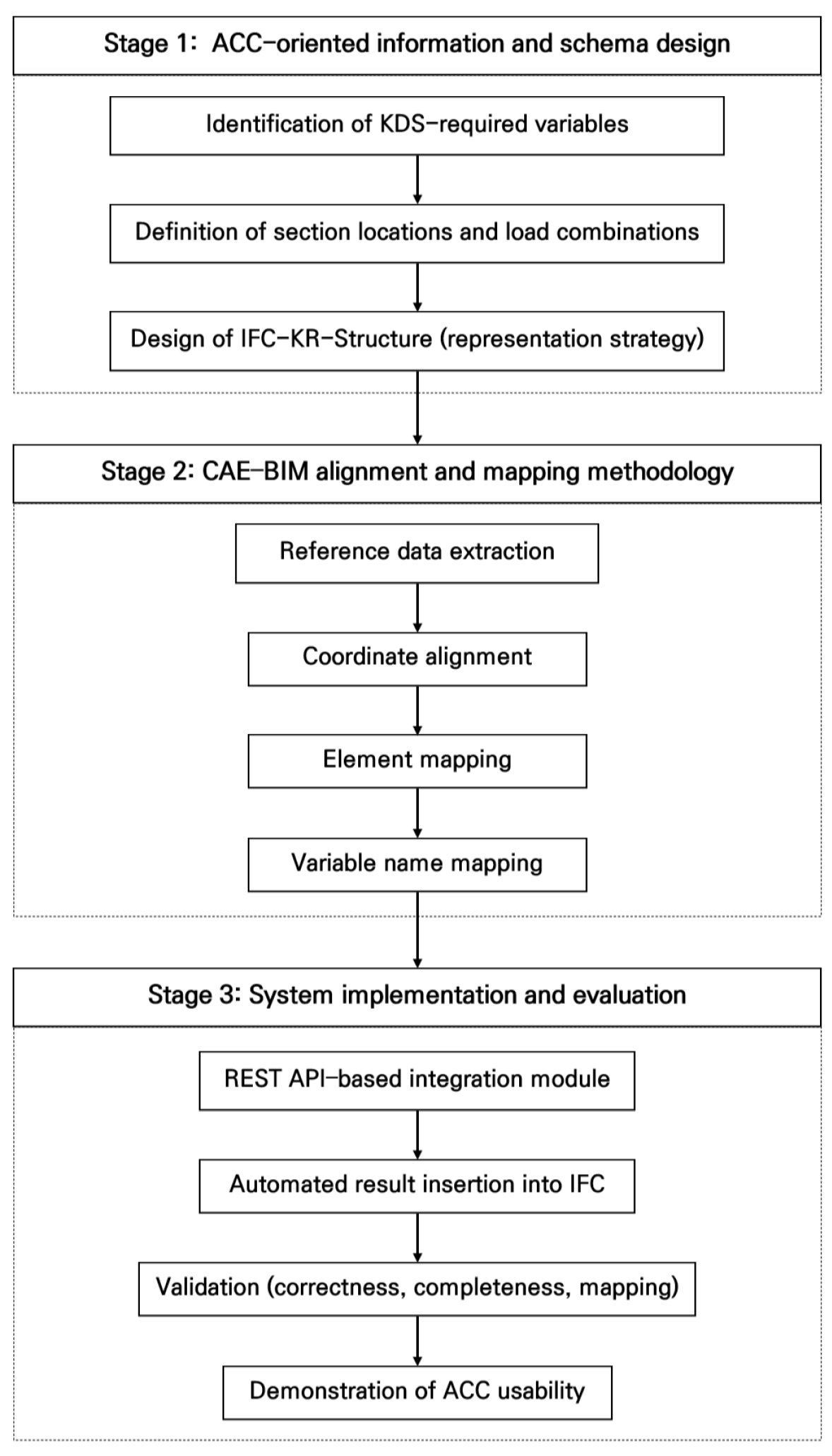
Figure 4.
CAE element level structure of analysis results for ACC.
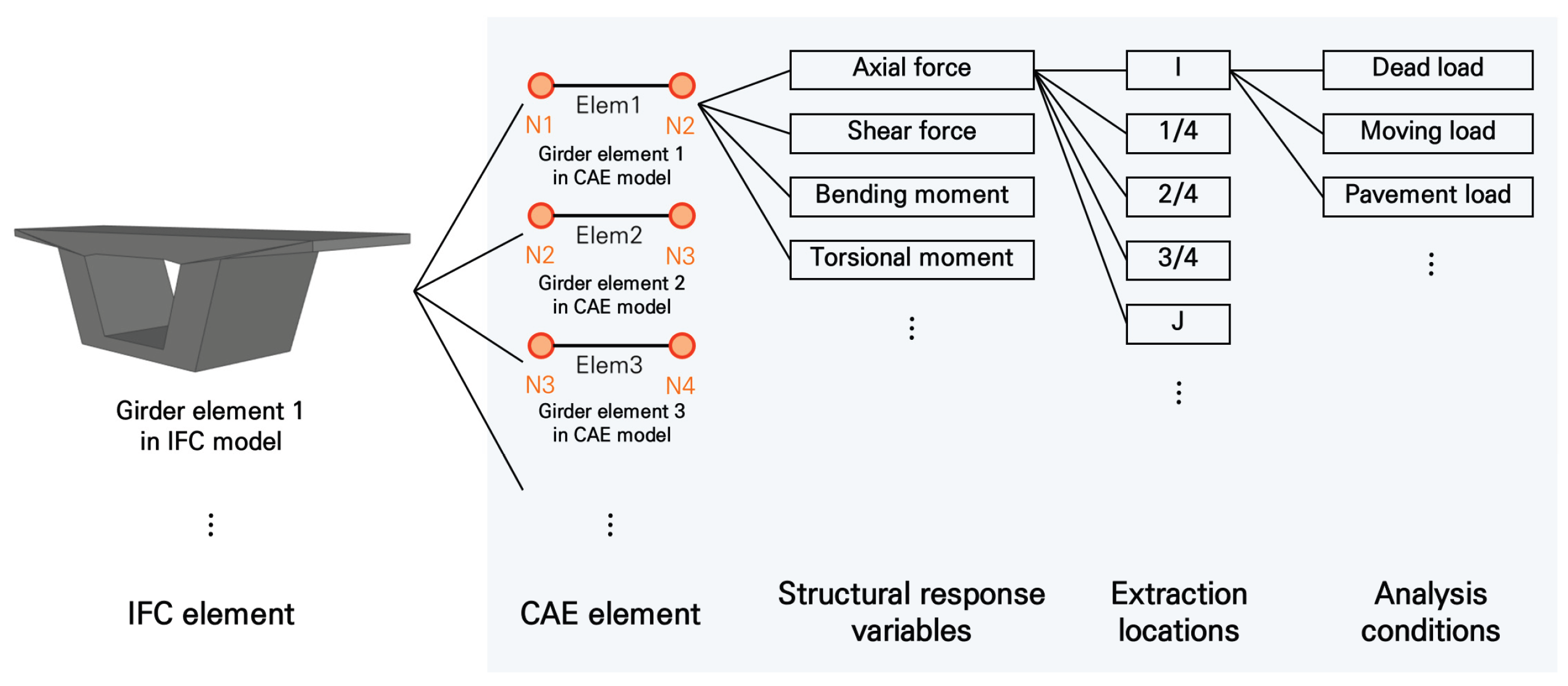
Figure 5.
Conceptual mapping between CAE-generated structural analysis results and their structured representation within the proposed IFC-KR-Structure.
Figure 5.
Conceptual mapping between CAE-generated structural analysis results and their structured representation within the proposed IFC-KR-Structure.
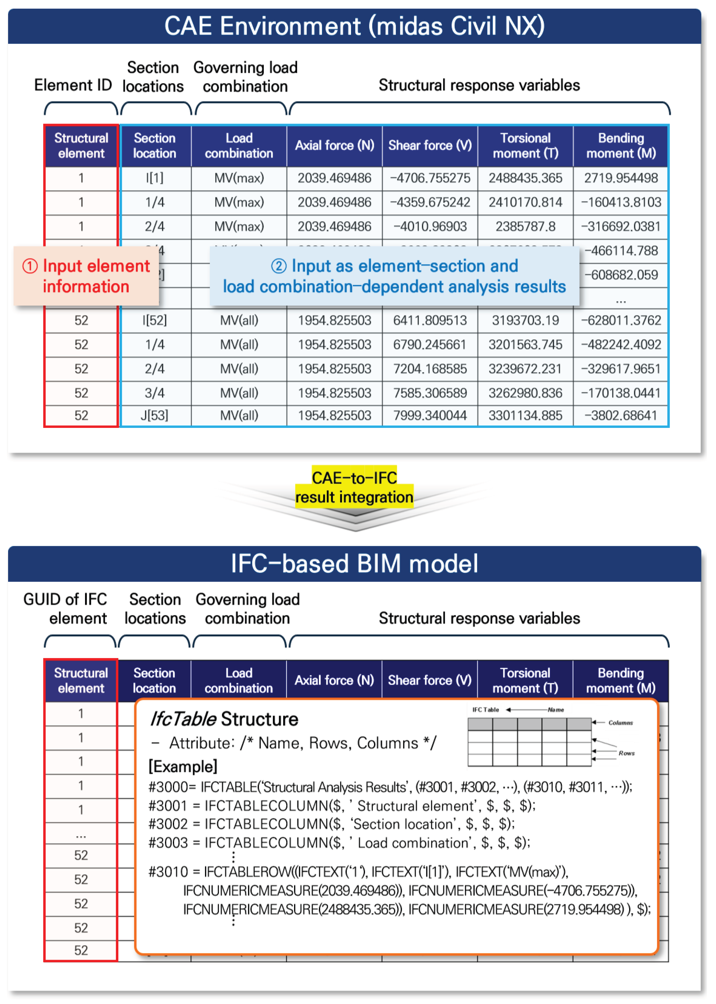
Figure 6.
Extraction of reference points from CAE and IFC models (PSC girder bridge example).
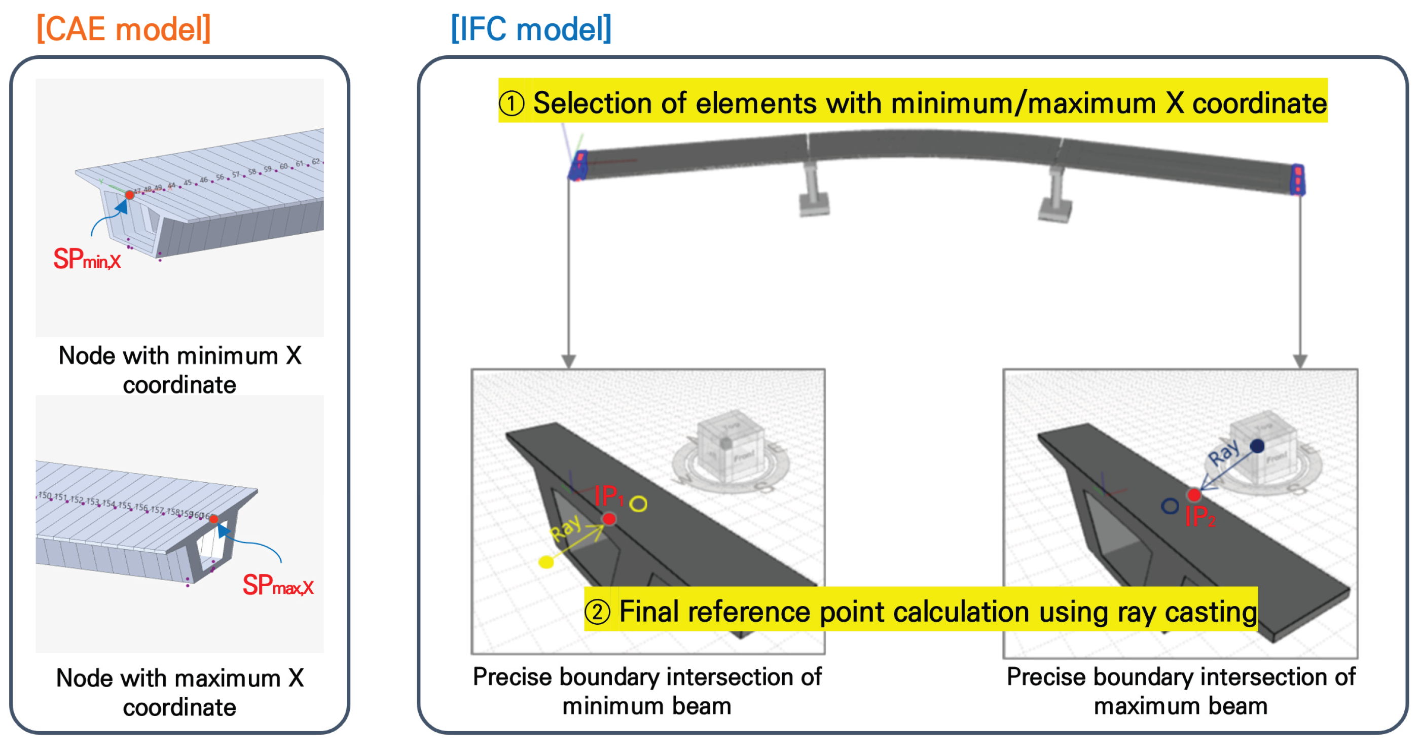
Figure 7.
Coordinate alignment between CAE and IFC models.
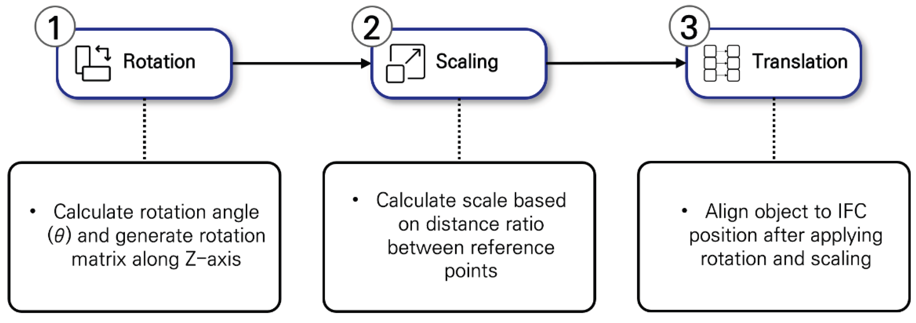
Figure 8.
Bounding box–based element mapping between CAE and IFC models.
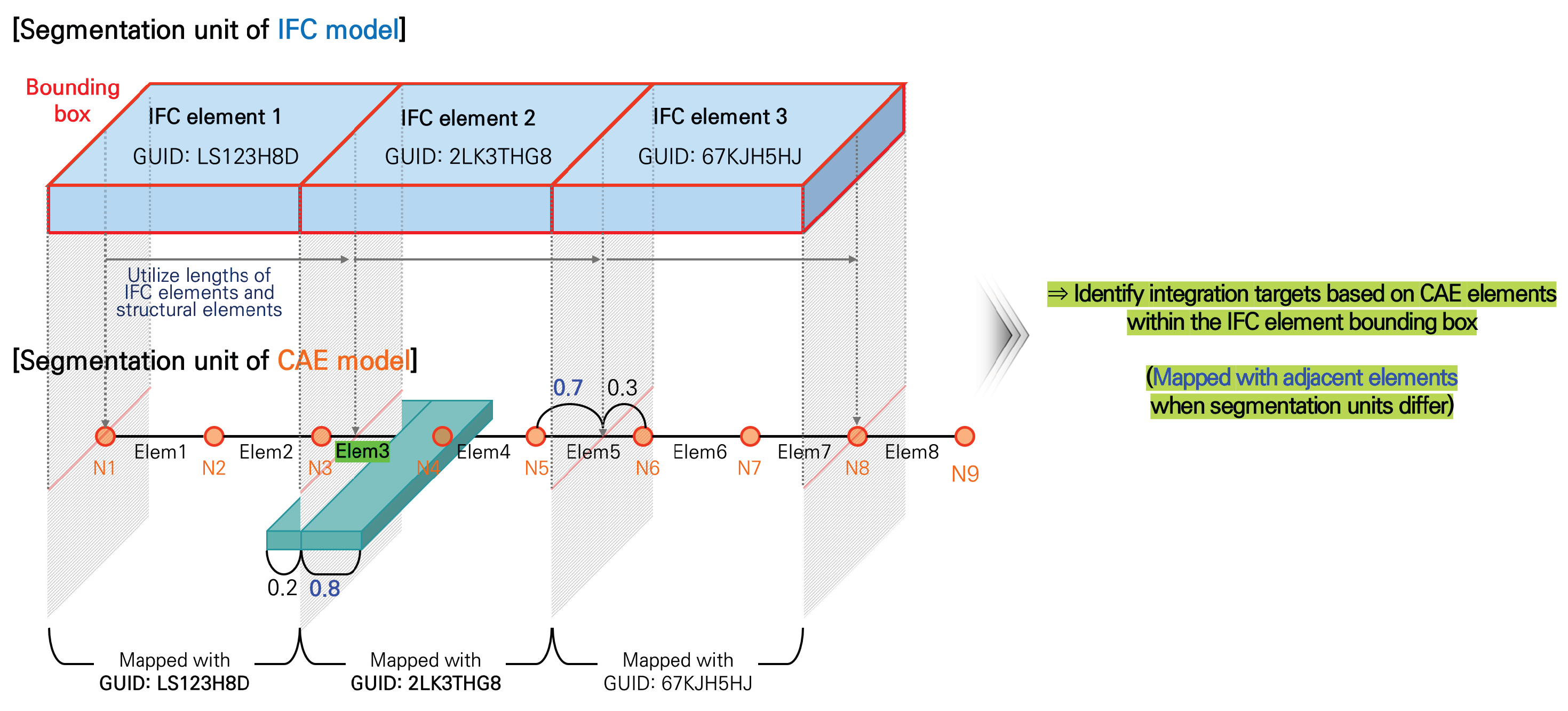
Figure 9.
Variable name mapping table for structural analysis result integration.
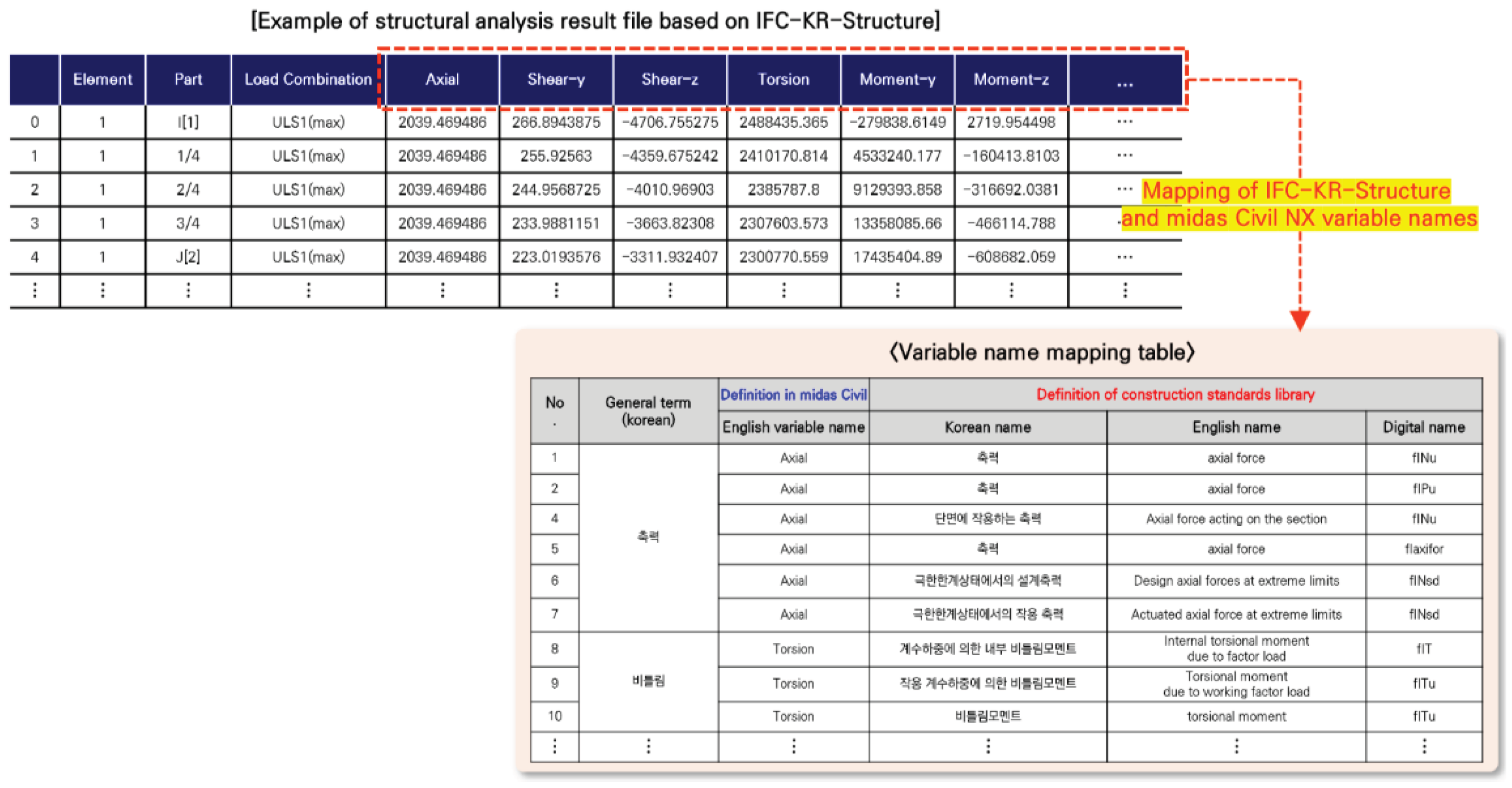
Figure 10.
Functional components of the IFC-KR Toolkit for REST API–based structural analysis result integration.
Figure 10.
Functional components of the IFC-KR Toolkit for REST API–based structural analysis result integration.
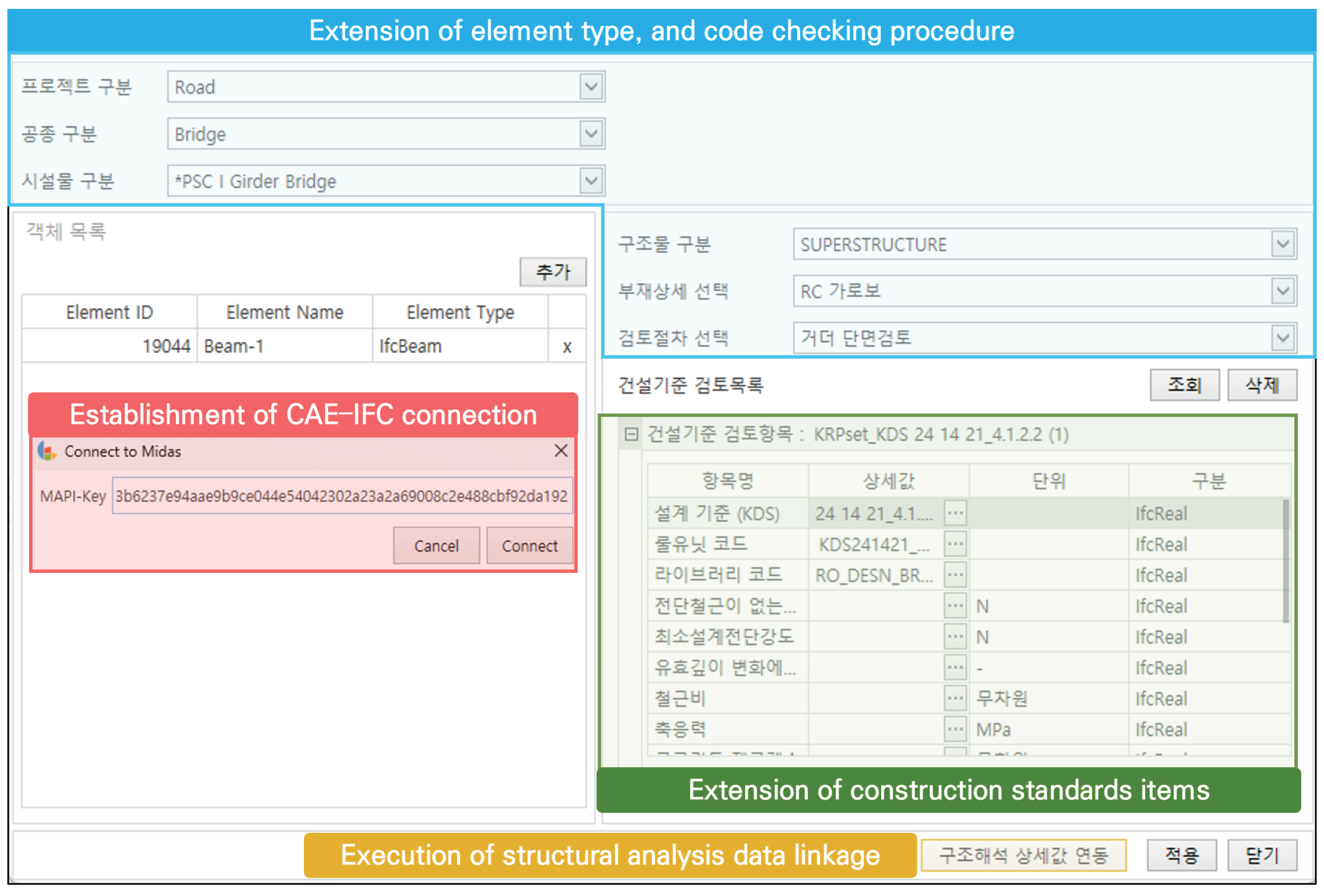
Figure 11.
Three-stage workflow for demonstrating downstream BIM-based ACC usability using the extended IFC model.
Figure 11.
Three-stage workflow for demonstrating downstream BIM-based ACC usability using the extended IFC model.
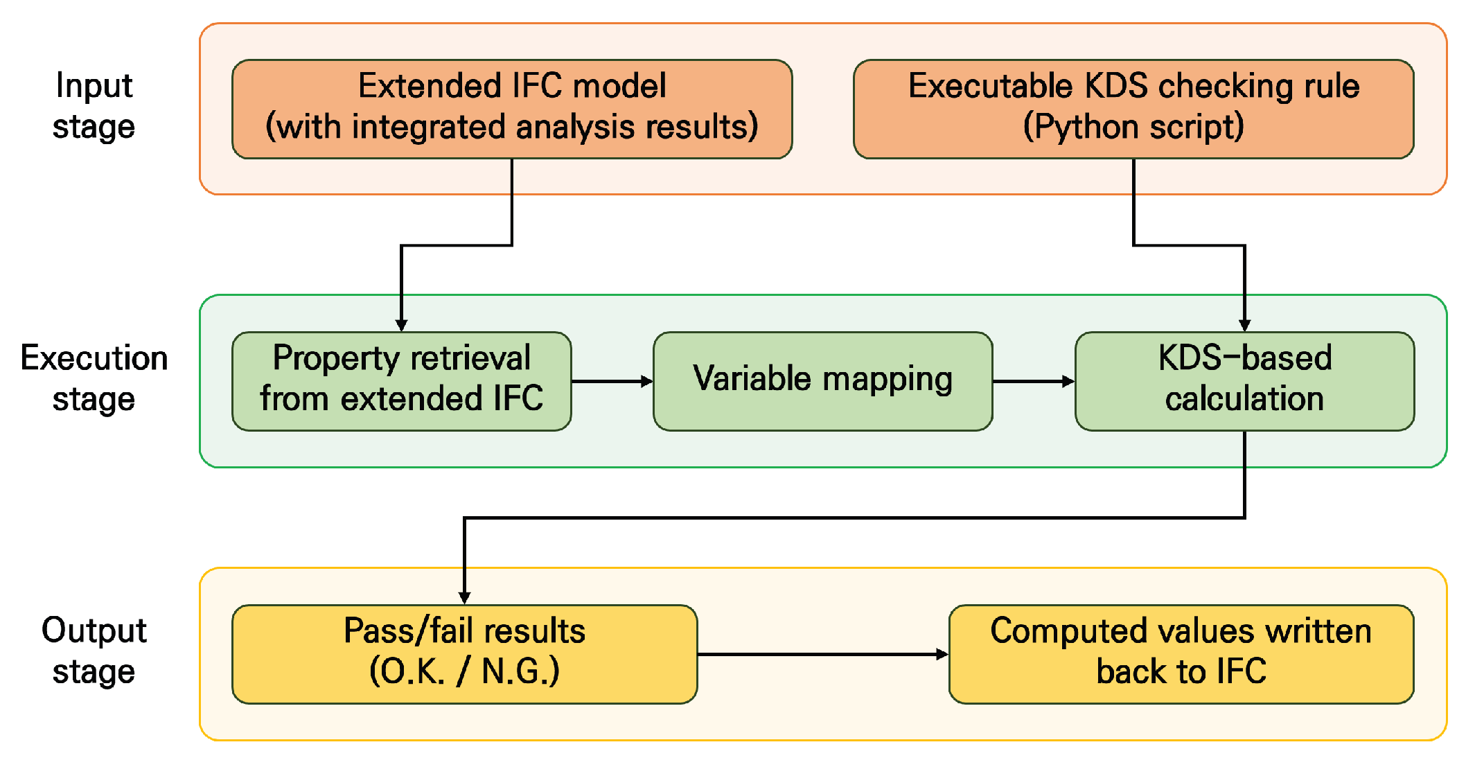

Table 1.
Structural analysis variables required for KDS-based structural code compliance checks.
| Structural Variable | Representative KDS Clause | Role in Code Checking |
| Axial force | KDS 24 14 21 4.1.2.2 | Used to evaluate interaction effects and determine design shear strength in PSC members. |
| Shear force | KDS 24 14 21 4.1.4.2 | Used to calculate shear demand and verify shear capacity against design limits. |
| Bending moment | KDS 24 14 21 4.1.1.2 | Used to assess flexural demand, cracking conditions, and minimum eccentricity requirements. |
| Torsional moment | KDS 24 14 21 4.1.3.2 | Used to determine required torsional reinforcement and verify torsional safety. |
Table 2.
Quantitative agreement of all tested entries.
| Metric | Result (by element type) |
| Total number of compared entries | 720 (girders) |
| 240 (copings) | |
| 360 (columns) | |
| 480 (pier foundations) | |
| Mean absolute difference | 0.0000 |
| Maximum absolute difference | 0.0000 |
| Exact match rate | 100% |
Table 3.
Example of value agreement for a representative element (illustrative subset).
| Element ID (IFC) | Load Combination | Variable | Section | CAE value | IFC value | AbsoluteDifference |
| 19044 | Dead load | Shear force | I | -832.12 kN | -832.12 kN | 0.00 |
| 19044 | Dead load | Shear force | 1/4 | -832.12 kN | -832.12 kN | 0.00 |
| 19044 | Moving load | Axial force | I | -6.63 kN | -6.63 kN | 0.00 |
| 19044 | Moving load | Axial force | 2/4 | -3.28 kN | -3.28 kN | 0.00 |
| 19044 | Pavement load | Bending moment |
2/4 | -4,116.36 kN∙m | -4,116.36 kN∙m | 0.00 |
| 19044 | Pavement load | Bending moment |
J | -3,698.76 kN∙m | -3,698.76 kN∙m | 0.00 |
| 19044 | Moving load | Torsional moment |
1/4 | 138.1 kN∙m | 138.1 kN∙m | 0.00 |
| 19044 | Moving load | Torsional moment |
J | 414.29 kN∙m | 414.29 kN∙m | 0.00 |
Note: Full validation was conducted across all sampled elements; only a subset is shown here for clarity.
Table 4.
Completeness of transferred data.
| Item | Result (by element type) |
| Expected number of entries | 720 (girders) |
| 240 (copings) | |
| 360 (columns) | |
| 480 (pier foundations) | |
| Actual number of stored entries | 720 (girders) |
| 240 (copings) | |
| 360 (columns) | |
| 480 (pier foundations) | |
| Completeness ratio | 100% |
| Missing entries | 0 |
Table 5.
Element mapping performance.
| Item | Result(IFC element level) |
| Number of tested IFC elements | 4 (girders) |
| 1 (copings) | |
| 1 (columns) | |
| 1 (pier foundations) | |
| Successfully mapped IFC elements | 4 (girders) |
| 1 (copings) | |
| 1 (columns) | |
| 1 (pier foundations) | |
| Mapping success rate | 100% |
| Manual correction required | No |
Table 6.
Required variables for KDS checking and data origin.
| Variable | Description | Unit | Source |
| Axial force (N) | Axial force | N | Imported via this study (CAE → IFC) |
| Amount of main tensile reinforcement ( |
Amount of main tensile reinforcement |
N | BIM / Design property |
| Cross-sectional area () | Cross-sectional area | mm2 | BIM / Design property |
| Abdominal width of section () |
Abdominal width of section | mm | BIM / Design property |
| Material factor () | Material factor of concrete |
- | BIM / Design property |
| Moment of inertia () | Moment of inertia | mm4 | Design input |
| Moment of inertia () | Moment of inertia of the section above the centroid about the centroid axis |
mm4 | Design input |
| Distance from the starting point of the transfer length to the cross section being examined ( | Ratio of Transfer length of prestressing tension members to Distance from the starting point of the transfer length to the cross section being examined | Dimension less |
Design input |
| Material factor () | Material factor of reinforcing bar |
Dimension less |
Design input |
| Yield strength () | Standard yield strength of rebar | MPa | Design input |
Table 7.
Example of ACC outputs recorded in the extended IFC model.
| Property | Value | Unit |
| Design shear strength | 1,274.91 | kN |
| Axial force used in calculation | 748.93 | kN |
| Checking result | O.K. | – |
| 1 | Computational geometry technique in which a ray is projected from a reference point or line to detect intersections with geometric surfaces |
Disclaimer/Publisher’s Note: The statements, opinions and data contained in all publications are solely those of the individual author(s) and contributor(s) and not of MDPI and/or the editor(s). MDPI and/or the editor(s) disclaim responsibility for any injury to people or property resulting from any ideas, methods, instructions or products referred to in the content. |
© 2026 by the authors. Licensee MDPI, Basel, Switzerland. This article is an open access article distributed under the terms and conditions of the Creative Commons Attribution (CC BY) license.
Copyright: This open access article is published under a Creative Commons CC BY 4.0 license, which permit the free download, distribution, and reuse, provided that the author and preprint are cited in any reuse.


