
Submitted:
21 January 2026
Posted:
22 January 2026
You are already at the latest version
Abstract
We address the control problem of a hybrid photovoltaic-grid water pumping system. This system includes a photovoltaic panel, an AC/DC PWM rectifier connected to an electric grid, a DC/AC PWM inverter paired with a Multiphase Induction Motor MPIM, and a centrifugal water pump. The control objectives are to ensure that the water pump flow rate follows a reference signal, regulate the norm of the rotor flux of the motor to its nominal value, maintain the DC link voltage at a reference value for optimal power point tracking (MPPT), and achieve satisfactory power factor correction (PFC). A nonlinear model of the controlled system is developed, followed by the synthesis of a multiloop nonlinear controller using the backstepping technique. This controller ensures global asymptotic stability in closed-loop operation and achieves all control objective.
Keywords:
Multiphase Induction Motor
; photovoltaic arrays
; MPPT
; nonlinear control
; backstepping technique
; Lyapunov stability
1. Introduction
In Morocco, the Ministry of Energy Transition and Sustainable Development has significantly advanced agricultural energy efficiency by promoting solar-powered water pumping systems. These systems, noted for their low maintenance and operational costs, provide a sustainable alternative to traditional energy sources like butane gas and diesel [1]. The adoption of solar pumping has surged, with more than 10,000 systems installed between 2019 and 2020, increasing the total to over 40,000. This expansion is supported by a reduction in photovoltaic panel costs and the economical price of solar pumping at 0.44 dirhams per cubic meter of water-substantially lower than the costs of conventional energy sources [1]. Advanced control strategies have been developed for induction motors in hybrid grid-photovoltaic systems to further augment the viability of solar energy in remote agricultural applications [2,3,4,5,6,7]. These approaches utilize advanced methods, including Indirect Double Integral Sliding Mode Control for Maximum Power Point Tracking (MPPT) and fuzzy logic, to optimize dynamic performance, thereby improving both efficiency and reliability [4]. Specifically, systems combining photovoltaic and battery storage are designed to ensure a continuous water supply under varying climatic conditions [3]. Technologies such as Field-Oriented Control and Direct Torque Control for induction motor drives have significantly improved operational efficiency and system robustness, minimizing energy losses and optimizing overall performance [5,6,8]. Grid-connected setups utilize Synchronous Reluctance Motors for improved power quality and continuous supply, even during grid power outages [9]. Additionally, the strategic integration of Voltage Source Inverters with existing motor windings facilitates efficient power exchanges between the solar power systems and the grid, minimizing the need for additional power electronics and enhancing overall energy management [10]. This study seeks to devise a control strategy that concurrently governs the AC/DC Rectifier and the ‘DC/AC Inverter-Multiphase Induction Motor Pump’ system. The strategy is distinguished by its multi-loop design, featuring a current loop to ensure unit power factor operation in the coupling between the power supply network and the AC/DC rectifier. Additionally, a separate loop is employed to regulate the rectifier’s output voltage, ensuring maximum power extraction from the photovoltaic generator, regardless of variations in solar radiation [11]. Moreover, a dual-variable loop is developed to monitor variations in water flow rate and ensure the rotor flux norm remains at its nominal level. The control loops leverage Lyapunov and backstepping techniques to achieve stability and precision [12].
2. System Modeling
The system configuration depicted in Figure 1 consists of two main components: an AC/DC rectifier connected to a photovoltaic generator (PVG), and a DC/AC inverter that drives a multiphase induction motor (MPIM), which in turn operates a centrifugal water pump. The entire system is connected to a single-phase electrical grid, with both the rectifier and inverter employing Pulse Width Modulation (PWM) technology for efficient electrical conversion. The PV generator consists of 30 SM55 photovoltaic modules connected in series.
2.1. Photovoltaic Generator Model
Solar cells convert sunlight directly into electrical energy. The equivalent circuit of a photovoltaic (PV) module is illustrated in Figure 2, as described in the established literature [13,14,15,16].
The ideal performance of a solar array, often represented in the current-voltage (Ip-Vp) characteristics where the series resistance (Rs) is assumed zero and the shunt resistance (Rsh) infinite, is described by:
where
Here, Iph represents the photocurrent generated under specific radiation conditions; Io is the diode’s reverse saturation current; Ior is the saturation current at the reference temperature; Ior denotes the short-circuit current under standard conditions (298.15 K and 1 kW/m²); KI is the temperature coefficient at Iscr; λ denotes solar irradiance; EGO is the band gap energy of silicon; γ is the diode ideality factor; Tr is the reference temperature; T is the actual cell temperature; k is Boltzmann’s constant; and q is the electron charge. Detailed formulas for Iph and Io are provided in sources such as [15], highlighting their dependency on T and λ. The photovoltaic generator (PVG) is composed of multiple strings of PV modules connected in series and parallel configurations to achieve the required voltage and current levels. This setup exhibits nonlinear current-voltage (Ig-Vg) characteristics, ideally expressed as:
In this equation, Ig denotes the current flowing through the PVG, while Vg represents the voltage across the PVG. The constant Ag = A/Ns adjusts A to account for the number of series-connected cells, while Iog= Np Io and Iphg=Np Iph scale the saturation current and photocurrent, respectively, based on Np, the number of parallel paths within the PVG. The specific PV module used in this study is the SM55, which consists of 36 mono-crystalline cells connected in series. The electrical specifications for this array are outlined in Table 1.
2.2. Modeling AC/DC Rectifier
Connected to the power network, the H-bridge converter configuration consists of four IGBTs (refer to Figure 1). The behavior of this subsystem is described by Kirchhoff’s laws, resulting in the following differential equations:
Here, ie is the current through the inductor Lo, Vg is the voltage across the output capacitor 2C from the PV array, and Ig is the generated current from the photovoltaic (PV) generator. The variable ve, defined as , represents the sinusoidal grid voltage, where E and ωe are the amplitude and angular frequency of the grid voltage, respectively. The variable io denotes the current flowing into the inverter, while s is the switching state of the H-bridge, which can toggle between -1 and 1:
Although this model effectively describes the physical dynamics of the rectifier, its switch-based nature makes it unsuitable for control design in traditional frameworks that require continuous control inputs. Thus, for the purposes of control, an average model is used (3-4) as follows [17]:
The variables x1,x2, and u represent the averaged values of ie, Vg, and s over switching periods, respectively.
2.3. Modeling “DC/AC Inverter – MPIM” Association
The dynamic model of a Multiphase Induction Motor (MPIM) in the stator-oriented (α,β) coordinates is given by [18,19,20]:
This model incorporates key parameters such as the rotor and stator resistances (Rr, Rs), inductances (Lr, Ls), mutual inductance (Msr), number of pole pairs (p), system inertia (J), and friction coefficient (f). The stator voltages vsα and vsβ can be independently controlled, linking them directly to the respective control actions:
This setup allows for precise control over the motor's behavior, leveraging modern PWM techniques to adjust the motor's operation dynamically. The variables u1 and u2 are averaged representations of the (α,β) components of the multiphase duty ratio system signals (k1,k2,k3,k4,k5). These control signals are derived by applying the Park transformation to the PWM signals and averaging over the PWM cycles. The variable io denotes the input current to the inverter, and the binary signals k1, k2, k3, k4, k5 are defined by the following switching logic:
Additionally, we define the averaged state variables for the control system:
where the overline notation, ∙ ‾, indicates averaging over PWM periods.
For modeling purposes, the averaged dynamic system is represented by the following set of differential equations:
2.4. Modeling the Centrifugal Pump
Centrifugal pumps, commonly used in photovoltaic energy applications, apply a load torque:
Correspondingly, the flow rate Q of the pump varies proportionally with the rotor speed:
where G and κ are constants specific to the centrifugal pump's characteristics.
2.5. System Model
The state-space equations previously derived are consolidated into a comprehensive global state-space model representing the entire system, including the Multiphase Induction Motor, Centrifugal Pump, and the associated DC/AC Inverter:
3. Controller Design
3.1. Control Targets
The system aims to achieve the following primary control Targets:
(1) Optimization of DC Link Voltage: The DC link voltage Vg must precisely follow a state-dependent reference voltage Vgref,=F(P), where P represents the output power of the PVG. This function F is designed to ensure that Vg=Vgref aligns with the operating point of the PVG at its maximum power.
(2) Power Factor Correction Requirement (PFC): The output current ie from the rectifier must be sinusoidal and phase-aligned with the AC supply voltage ve.
(3) Regulation of Water Flow Rate: The water flow rate Q should follow a predefined reference signal Q"ref " .
(4) Regulation of Rotor Flux: The norm of the rotor flux should be controlled to match a reference value Φref, ideally its nominal value.
These controllers are developed using the backstepping control [12].
3.2. Optimization of DC Link Voltage
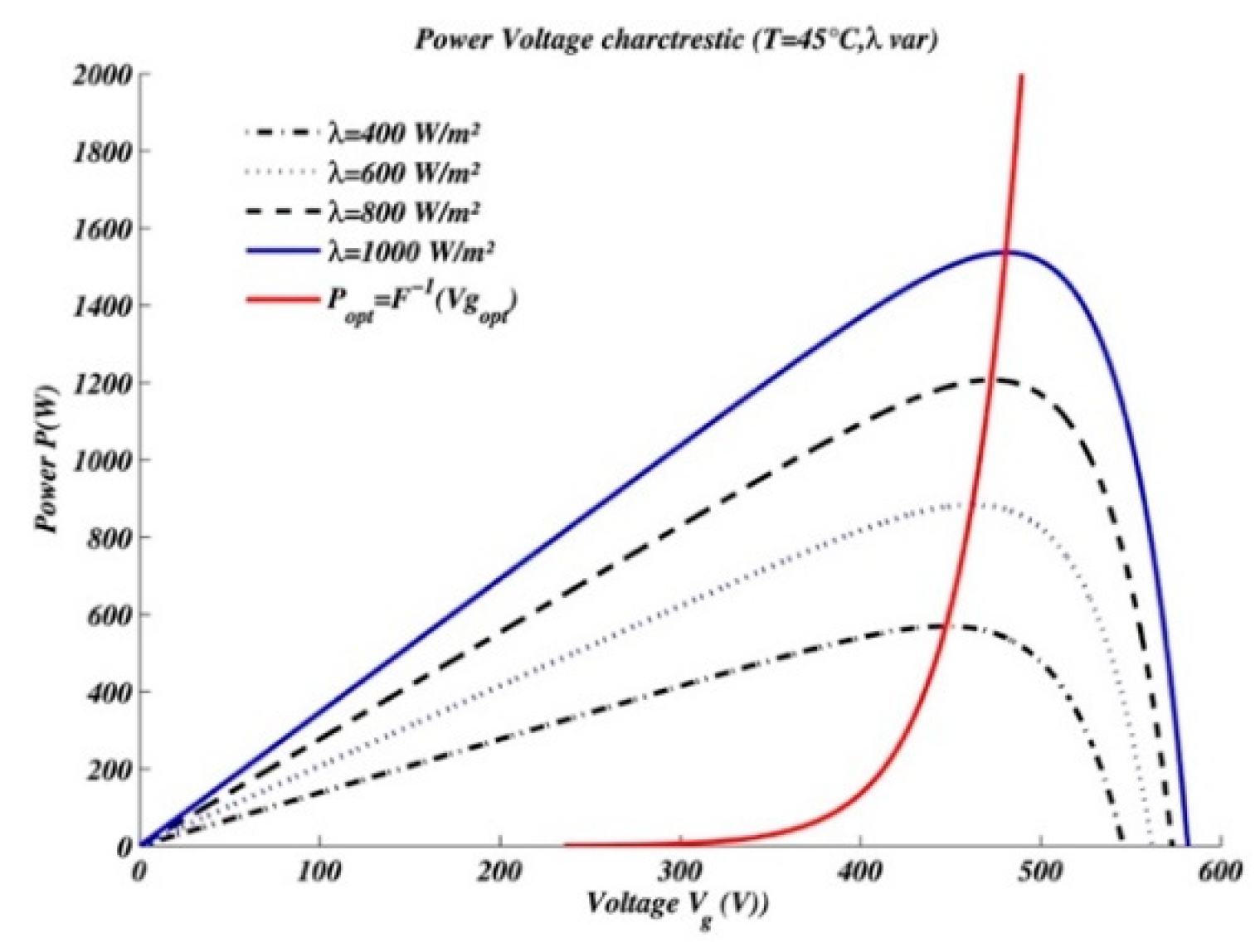
The voltage-reference optimizer is based on the power-voltage relationship (P-Vg) characteristics, which do not require the measurement of solar radiation λ. This design strategy is adapted to the typical operating conditions of the photovoltaic generator at 45∘ C, a common temperature under which the generator frequently operates. The objective here is to develop a voltage-reference optimizer that meets the Maximum Power Point Tracking criteria, dynamically calculating the optimal voltage Vgopt to guarantee maximum power extraction and efficient transmission to the multiphase induction motor via the DC/AC inverter.
Figure 3.
Power-voltage (P-V) characteristics of the PVG, under constant temperature and varying radiation.
Figure 3.
Power-voltage (P-V) characteristics of the PVG, under constant temperature and varying radiation.
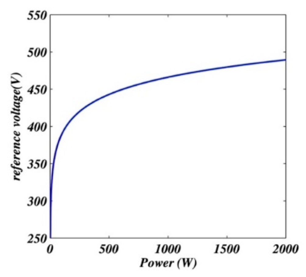
The voltage-reference optimizer is formulated as a polynomial function Vgopt=F(Popt), as detailed in [11]:
In this formula, the coefficients hi represent the specific characteristics of the photovoltaic generator system (PVG).
Figure 4.
Optimal power-voltage characteristic obtained from polynomial interpolation for the SM55 module series.
Figure 4.
Optimal power-voltage characteristic obtained from polynomial interpolation for the SM55 module series.
3.3. Power Factor Correction (PFC)
The objective of Power Factor Correction (PFC) is to keep the grid current sinusoidal and in phase with the AC supply voltage. A control regulator fine-tunes the current x1 to align with the reference signal , defined as:
where k is a real parameter influencing the direction of power flow. Introducing the current tracking error:
Given the dynamics in (6), the error evolves according to:
A stabilizing control strategy is developed using a quadratic Lyapunov function , ensuring that the time derivative becomes negative definite when the control input is:
where c1 is a positive design parameter. The stability and effectiveness of this control strategy are outlined in the subsequent proposition, demonstrating straightforward proof from the conditions defined.
Proposition 1.
Given the system described by the current equation (6) and the control law (20), with a positively set c1, and provided the reference and its first derivative are available, the following properties hold:
- The current loop governed by exhibits global exponential stability, implying that z1 diminishes exponentially irrespective of initial conditions.
- Additionally, if k converges to a finite value, then the PFC requirement is asymptotically met on average, meaning the average input current x1 exponentially approaches the reference over time.
3.4. Regulation of DC Link Voltage
The objective is to formulate a control law for adjusting the ratio k in (17) to regulate the inverter input voltage to a target reference value . Establishing the relationship between the control input k and the output voltage x2 is critical, as highlighted in the following proposition.
Proposition 2.
Under the assumptions previously established in Proposition 1, the power rectifier described by (6-7) and controlled via (20) exhibits the following behavior:
- The output voltage x_2 adjusts in response to changes in k according to:
- The squared voltage responds to adjustments in k as follows:
Given that the reference for the squared voltage is , the tracking error evolves according to:
This equation includes periodic terms due to , where . To stabilize the system described by (23), a quadratic Lyapunov function is used:
By setting the control law to neutralize periodic fluctuations and ensure a negative definite , we simplify:
Considering practical implementation and avoiding excessive control chattering, a filtered version of the control solution is proposed:
This design uses regulator parameters d and c2, both positive constants. The complete dynamics and control effectiveness are summarized in the following proposition:
Proposition 3.
With the AC/DC rectifier system defined by (67) and incorporating control laws (20) and (26), the closedloop dynamics in coordinates are governed by:
where:
3.5. Design of Water Flow Rate and Rotor Flux Norm Regulator
The control of water flow rate and flux norm poses a significant challenge, involving the entire system composed of the induction machine and centrifugal pump, as detailed in equations (15c - 15g) and (14). The reference for the water flow rate, Qref , is set as a bounded and differentiable function of time, with both its first and second derivatives being well-defined and limited. This ensures that Qref can be efficiently managed through second-order linear filters. The flux norm reference, Qref, is established at its nominal value.
The controller is designed in two stages using the tuning functions backstepping adaptive method [12]. Initially, we define the tracking errors:
Step 1. We employ the state equations ( 15d- 15g) to describe the dynamics of errors z3 and z4:
In (31a) and (31b), the expressions and act as virtual control signals. To stabilize the error system, we set:
where c3 and c4 are positive design parameters. Employing a Lyapunov function:
yields:
This formulation indicates global asymptotic stability. Introducing new errors for unactualized virtual controls:
Thus, the modified dynamics of the errors z3 and z4 are:
Step 2: The second phase of the design involves selecting the actual control signals, u1 and u2, to ensure that all errors converge to zero. We begin by examining how these errors depend on the control signals . Starting with z5, from (35a) we derive:
which simplifies to:
with μ2 defined as:
For z6, we have:
which simplifies to:
with v2 defined as:
To control this system, we define an augmented Lyapunov function:
whose time derivative is:
yielding:
In this formulation, c5 and c6 are introduced as new positive real design parameters.
The dynamics of the system as described by equation (45) suggest that the control inputs u1 and u2 must be carefully selected to nullify the expressions within the curly brackets on the right side of (45). By zeroing these terms and solving the resulting system of linear equations, we obtain the control law:
where the coefficients are defined as:
It is notable that the matrix is nonsingular. Indeed, its determinant,
does not vanish in practice due to the machine's inherent magnetic flux. Implementing the control law (46) for u_1 and u_2 leads to:
demonstrating that this is a negative definite function over the state space defined by .
This leads us to the following proposition:
Proposition 4.
Consider the closed-loop system comprising the induction machine, modeled by (15c) - (15g), and the nonlinear control laws (36a), (36b), (38), and (41). The system exhibits the following properties:
- The closed-loop error system, in the coordinates , follows the equations:
- This linear system is globally asymptotically stable with respect to the Lyapunov function V3, ensuring that errors , diminish exponentially fast regardless of initial conditions.
4. Results from Simulation
The control strategy outlined in Section 3, which integrates the optimizer (16) along with the control laws (20), (26), and (46), has been thoroughly evaluated through simulation. The specifications for the simulated system are as follows:
- Electric Grid: Single phase, 230V, 50Hz
- AC/DC Rectifier: Inductance Lo=16mH; Capacitance C=1.6mF; Modulation frequency 10 kHz
- Photovoltaic Modules: 30 series-connected SM55 modules, each rated at 55 W, detailed in Table 1.
- Multiphase Induction Motor: Nominal power Pn= 2.2 kW ; Voltage Usn=400V; Current Isn=5A; Frequency f=50Hz; Speed Ωn=1435rpm.
The design parameters ( , , ) were selected through trial and error, proving their efficacy in simulations. The experimental setup was modeled in Matlab/Simulink, utilizing a simulation timestep of 5μs, necessary to accommodate the 10 kHz switching frequency of the inverter and rectifier.
Radiation variation, depicted in Figure 5, includes scenarios of low (λ=200W/ m2) and high (λ=900 W/ m2) radiation. Simulations were performed at a constant temperature of 45∘ C. The graph shows how the voltage reference dynamically adjusts to changes in solar radiation, demonstrating the responsiveness of the system to environmental changes.
The control system drives the machine to operate at variable water flow rates, as illustrated in Figure 6. The rotor flux norm Φref , set at its nominal value of 1 Weber, shows successful convergence to the reference values, indicating precise control over both flow rate and rotor flux.
Figure 7 highlights the effectiveness of Power Factor Correction (PFC), demonstrating how the input current synchronizes with the grid voltage while the system adjusts to changes in solar radiation and load demands. Notably, the control ratio stabilizes rapidly after any fluctuations, showcasing the controller’s robustness and adaptability. The results confirm that the multiloop controller effectively meets its objectives, delivering satisfactory transient performance and efficiently managing various system states under changing environmental conditions. As shown in Figure 7, the upper graph presents the behavior of the measured input current. The current frequency remains consistent and synchronized with the voltage frequency. Specifically, the current either aligns with or is out of phase with the supply network voltage, which is typical during periods of low solar radiation when the photovoltaic (PV) generator produces insufficient power to meet the demands of the induction motor and centrifugal pump system. Conversely, during periods of high solar radiation, the PV generator produces excess power, which is then fed back into the grid. This behavior aligns with the requirements for Power Factor Correction (PFC). Additionally, the upper graph in Figure 7 shows that the control ratio stabilizes at a consistent value after transient fluctuations caused by changes in solar radiation and the water flow rate reference. It is important to note that the control ratio becomes negative when the system exports excess power to the grid.
5. Conclusions
This research tackles the challenge of achieving Maximum Power Point Tracking (MPPT) in the grid-connected photovoltaic systems. We propose a novel control strategy employing backstepping design controllers, derived from the system's nonlinear model (15a-15g). This approach integrates the dynamics of the DC/AC inverter with the three-phase grid inductor, thereby eliminating the need for a DC/DC chopper. To adapt to varying operational conditions, particularly fluctuations in solar radiation, a voltage reference optimizer is implemented.
The developed MPPT controller combines this optimizer with voltage reference generation (16) and control laws (46), offering a more efficient solution for identifying the maximum power point of the PV array. This method outperforms traditional techniques like Resistive Control Coefficient (RCC), Incremental Conductance (IncCond), and Perturb and Observe (P&O) by achieving MPPT without oscillations around the maximum power point and avoiding the pitfalls of using power, current, and voltage derivatives, which can lead to divide-by-zero errors.
The robustness and effectiveness of this MPPT controller have been validated through simulations, demonstrating its ability to meet control objectives under diverse environmental conditions.
Abbreviations
The following abbreviations are used in this manuscript:
| MPIM | Multiphase Induction Motor |
| PVG | Photovoltaic Generator |
| MPPT | Maximum Power Point Tracking |
| PFC | Power Factor Correction |
| PWM | Pulse Width Modulation |
| IncCond | Incremental Conductance |
| P&O | Perturb and Observe |
| RCC | Resistive Control Coefficient |
References
- Ministere de l'Energie des Mines et de l'Environnement ROYAUME DU MAROC. Strategie nationale de l'efficacite energetique a l'horizon 2030, August 2020.
- Salima Meziane, Riad Toufouti, and Loubna Atarsia. Non-linear adaptive control of induction motor drive for standalone photovoltaic water pumping system. In Handbook of Research on Modeling, Analysis, and Control of Complex Systems, pages 450-476. IGI Global, 2021.
- Zakaria Massaq, Abdelouahed Abounada, and Mohamed Ramzi. Robust non-linear control of a hybrid water pumping system based on induction motor. International Journal of Power Electronics and Drive Systems, 11(4):1995-2006, December 2020. [CrossRef]
- Iffouzar Koussaila, Khaldi Lyes, Kamal Himour, Deboucha Abdelhakim, Houari Azeddine, Ghedamsi Kaci, and Benkhoris Mohamed Fouad. Impact of polyphase induction motor on photovoltaic water pumping system. Journal Européen des Systèmes Automatisés, 53(6):763-770, December 2020. [CrossRef]
- Hussein M. Waly, Dina S. M. Osheba, Haitham Z. Azazi, and Awad E. El-Sabbe. Induction motor drive for pv water-pumping system with highgain non-isolated dc-dc converter. In 2019 IEEE Conference on Power Electronics and Renewable Energy (CPERE). IEEE, October 2019.
- Mustapha Errouha, Aziz Derouich, Saad Motahhir, and Othmane Zamzoum. Optimal control of induction motor for photovoltaic water pumping system. Technology and Economics of Smart Grids and Sustainable Energy, 5(1):1-11, February 2020. [CrossRef]
- Boudjana Said, Tadjine Mohamed, and Bouzidi belkacem. On robust control of induction motor with multicell inverter for pv pumping applications. In 2019 International Conference on Applied Automation and Industrial Diagnostics (ICAAID). IEEE, September 2019.
- S. Gheouany, H. Ouadi, C. Berrahal, S. El bakali, J. El bakkouri, and F. Giri. Multi-stage energy management system based on stochastic optimization and extremum-seeking adaptation. IFAC-PapersOnLine, 56(2):5457-5462, 2023. [CrossRef]
- Hina Parveen and Bhim Singh. Pv fed synchronous reluctance motor driven water pumping system with grid integration and seamless operability. In 2022 IEEE 10th Power India International Conference (PIICON), pages 1-6. IEEE, November 2022.
- Rajan V. Vamja and Mahmadasraf A. Mulla. Development of gridinteractive inverter utilising induction motor driven photovoltaic water pumping system. Iet Power Electronics, 13(15):3373-3383, September 2020. [CrossRef]
- A. El Fadili, F. Giri, and A. El Magri. Reference voltage optimizer for maximum power point tracking in triphase grid-connected photovoltaic systems. International Journal of Electrical Power E E Energy Systems, 60:293-301, September 2014. [CrossRef]
- M. Krstic, I. Kanellakopoulos, and P. Kokotovic. Nonlinear and Adaptive Control Design, volume 40. John Wiley & Sons, Inc., March 1995.
- J. A. Gow and C. D. Manning. Development of a photovoltaic array model for use in power-electronics simulation studies. IEEE Proceedings on Electric Power Applications, 146(2):193-200, 1999.
- A. Luque and S. Hegedus. Handbook of Photovoltaic Science and Engineering. John Wiley & Sons, Ltd, December 2003.
- Y. T. Tan, D. S. Kirschen, and N. Jenkins. A model of pv generation suitable for stability analysis. IEEE Transactions on Energy Conversion, 19(4):748-755, December 2004. [CrossRef]
- A. El Fadili, F. Cuny, A. El Magri, M. Stitou, F. Giri, J.M. Janik, and F.Z. Chaoui. Backstepping control of photovoltaic-grid hybrid power feed water pump. IFAC-PapersOnLine, 50(1):6540-6545, 2017. 20th IFAC World Congress. [CrossRef]
- R. Ortega, P. J. Nicklasson, and G. Espinosa-Perez. On speed control of induction motors. Automatica, 32(3):455-460, March 1996.
- A. El Fadili, F. Giri, A. El Magri, L. Dugard, and F. Z. Chaoui. Adaptive nonlinear control of induction motors through ac/dc/ac converters. Asian Journal of Control, 14(4):1470-1483, 2012. [CrossRef]
- A. El Fadili, F. Giri, and A. El Magri. Control models for induction motors, pages 15-40. Wiley & Sons, April 2013.
- C. BERRAHAL, A. El FADILI, F. GIRI, A. E. L. MAGRI, R. LAJOUAD, and I. E. L. MYASSE. Robustness of backstepping multiphase induction machine control in presence of open phases. IFAC-PapersOnLine, 55(12):794-799, 2022. [CrossRef]
Figure 1.
General diagram of the controlled system.
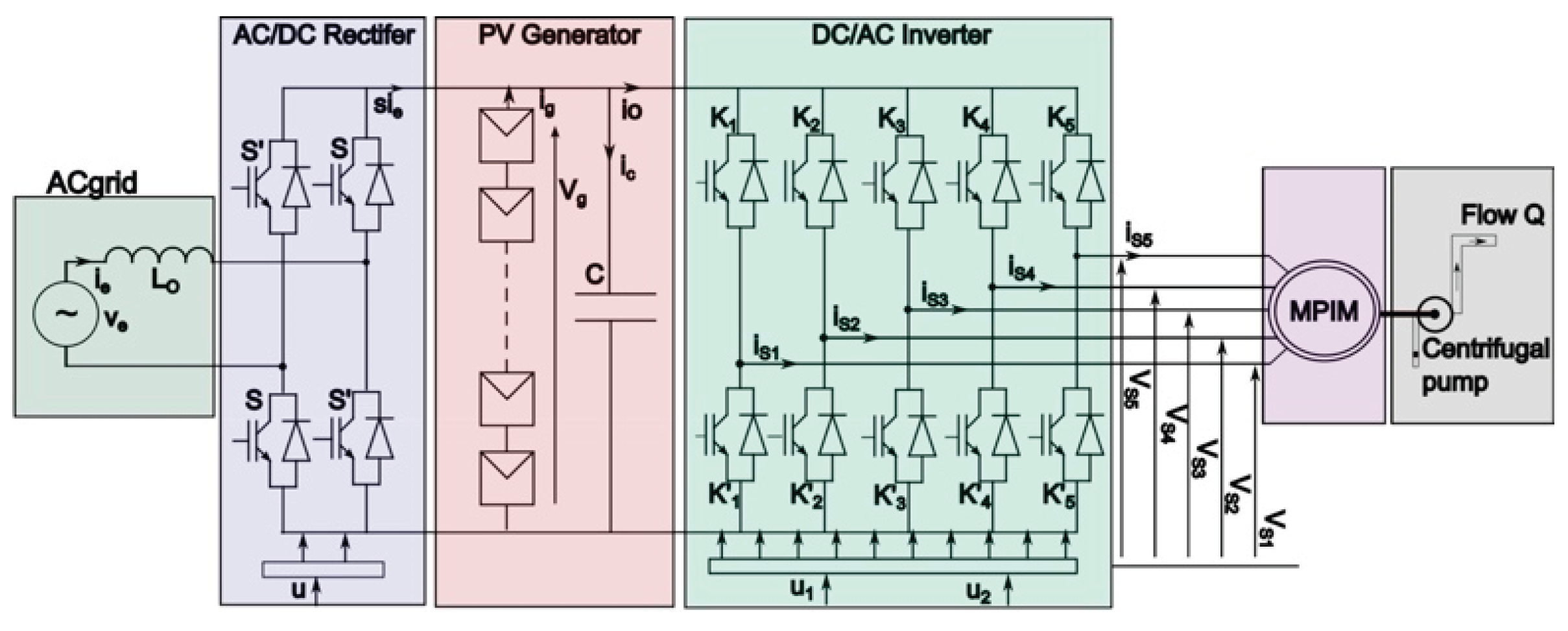
Figure 2.
Equivalent circuit of a PV module.
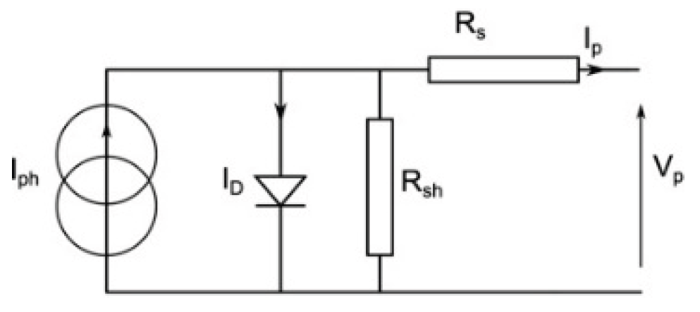
Figure 5.
Upper: Radiation λ variation (W/ m2 ), lower: Photovoltaic voltage Vg (V).
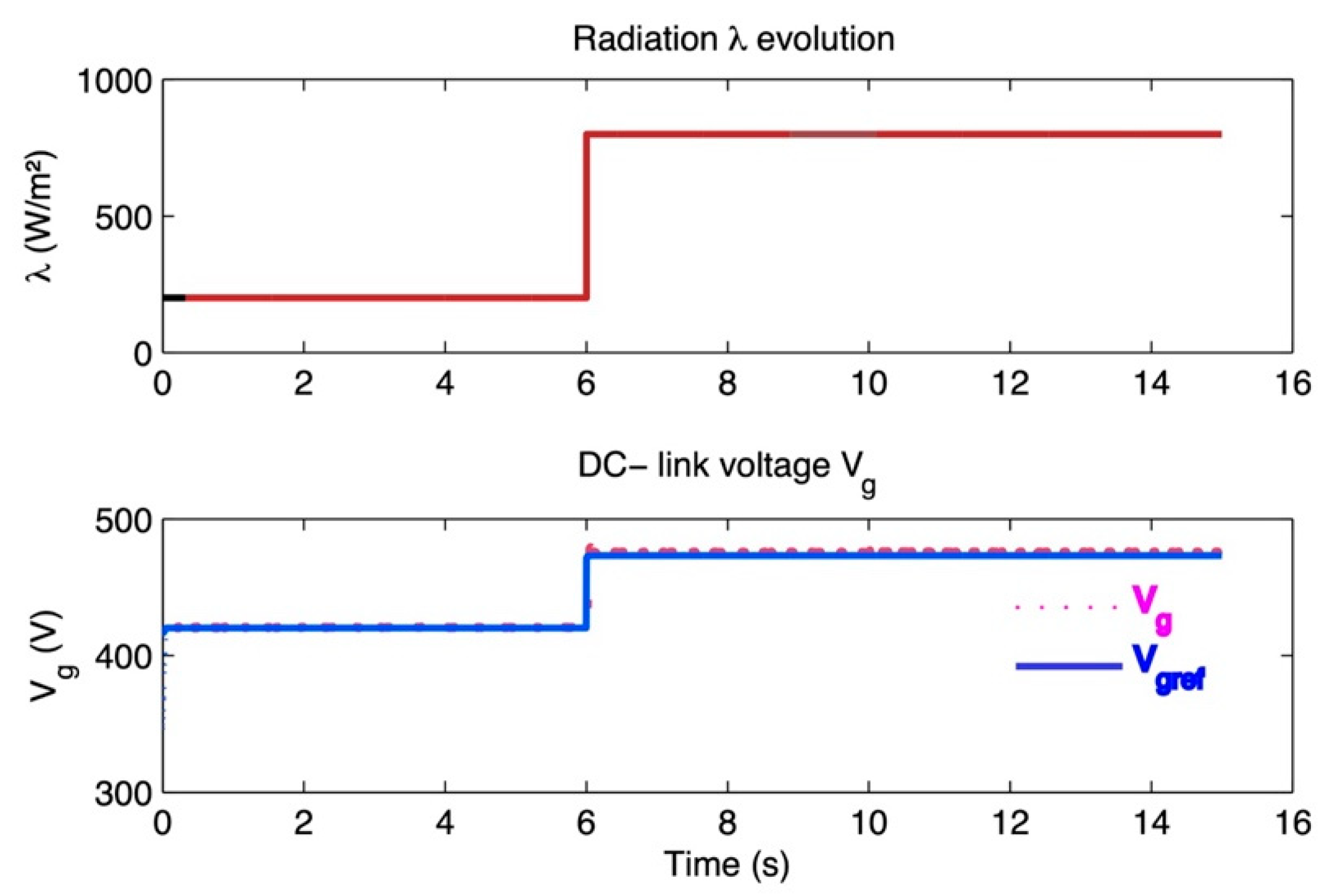
Figure 6.
Upper: Water flow rate Q(m3/h), lower: Rotor flux norm Φref (Wb).
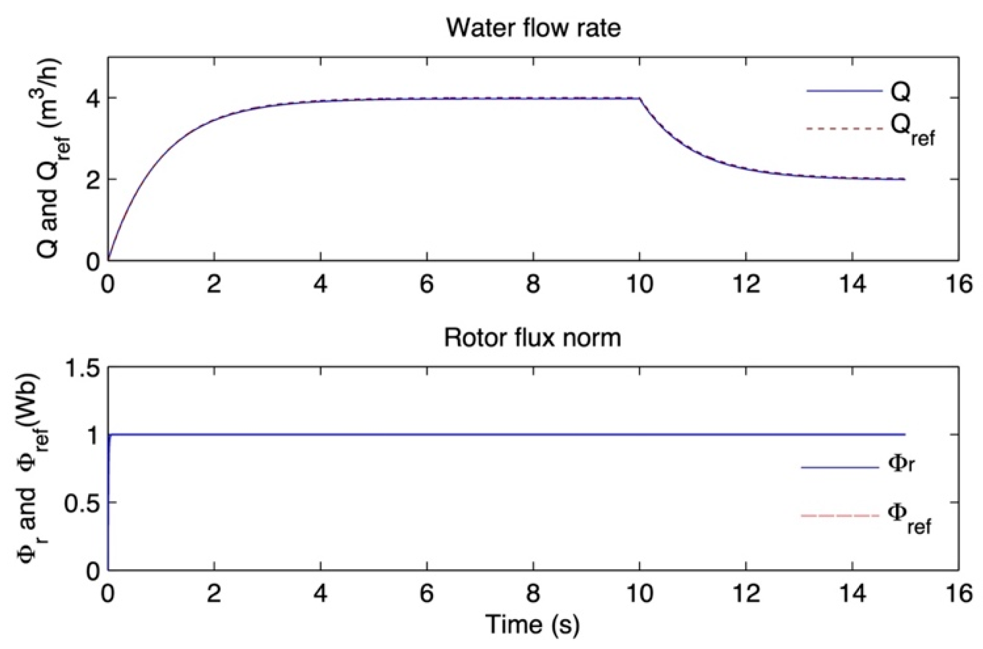
Figure 7.
Upper: Ratio k, lower: Zoom on the curves of ie and 0.01 ve over the time interval [14.9s, 15s].
Figure 7.
Upper: Ratio k, lower: Zoom on the curves of ie and 0.01 ve over the time interval [14.9s, 15s].
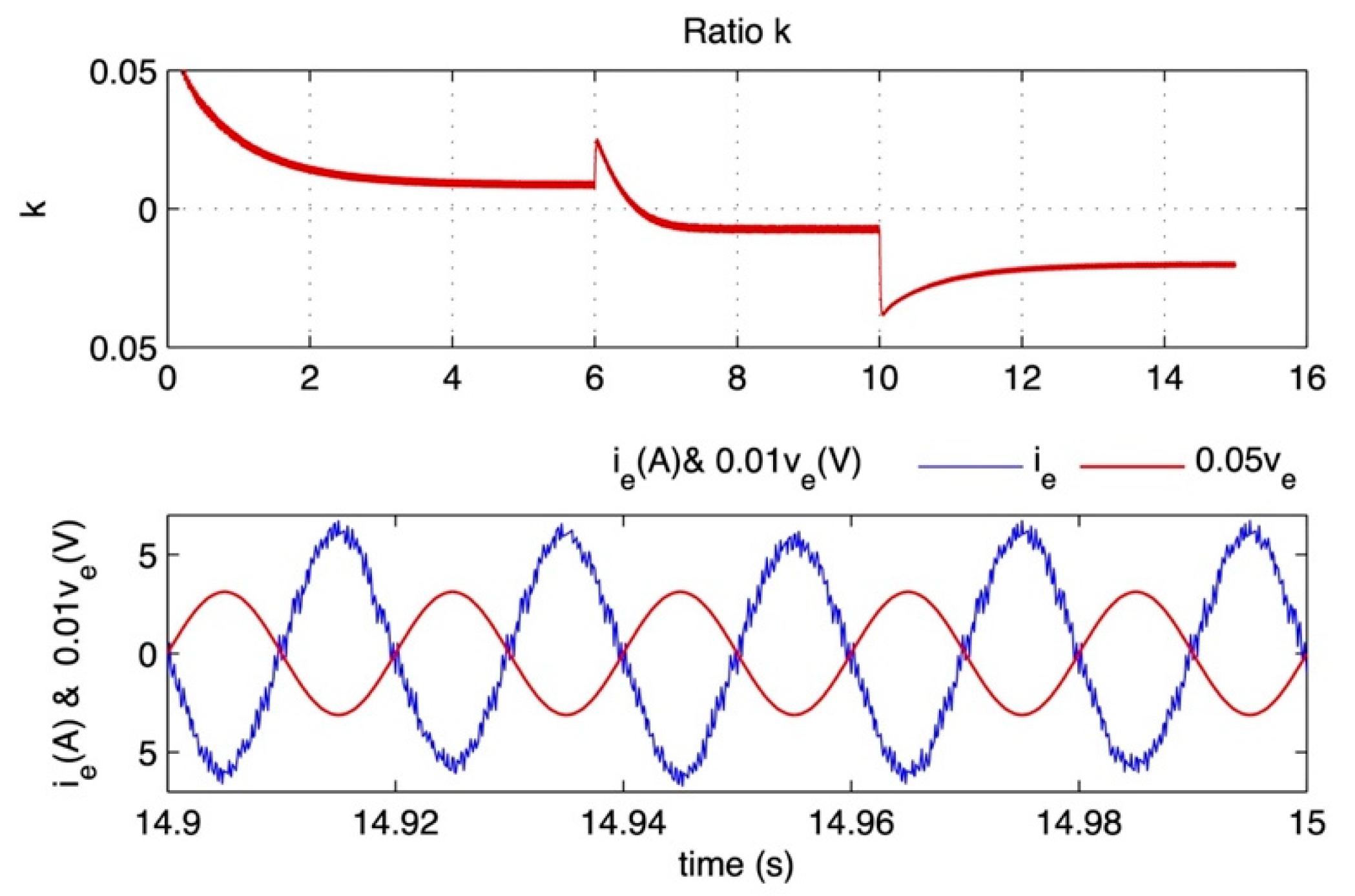

Table 1.
Electrical specifications of the SM55 solar module.
| Maximum Power | Pm (W) | 55 |
| Short circuit current | ISCR (A) | 3.45 |
| Open circuit voltage | Voc (V) | 21.7 |
| Voltage at max power point | Vm (V) | 17.4 |
| Current at max power point | Im (A) | 3.15 |
| Temperature Coefficient Isc | KI (A/K) | 4⋅10-4 |
Disclaimer/Publisher’s Note: The statements, opinions and data contained in all publications are solely those of the individual author(s) and contributor(s) and not of MDPI and/or the editor(s). MDPI and/or the editor(s) disclaim responsibility for any injury to people or property resulting from any ideas, methods, instructions or products referred to in the content. |
© 2026 by the authors. Licensee MDPI, Basel, Switzerland. This article is an open access article distributed under the terms and conditions of the Creative Commons Attribution (CC BY) license (http://creativecommons.org/licenses/by/4.0/).
Copyright: This open access article is published under a Creative Commons CC BY 4.0 license, which permit the free download, distribution, and reuse, provided that the author and preprint are cited in any reuse.


