
Submitted:
20 January 2026
Posted:
21 January 2026
You are already at the latest version
Abstract
In this paper, we propose a novel design model for an inertial switch that utilizes metal droplets as the sensing element. The overall device model comprises three components: the substrate layer, the functional structure layer, and the cover layer, along with the liquid metal. The metal droplets within the liquid storage tank are drawn towards the fixed electrode due to inertial forces. When the acceleration exceeds a predetermined threshold, the metal droplet covers the fixed electrode, closing the switch and allowing current to flow through the external circuit. Conversely, when the acceleration load is removed, the metal droplet retracts to the liquid storage tank, disconnecting the fixed electrode. This design is characterized by its simplicity, low manufacturing cost, and stable dynamic response. To evaluate the threshold acceleration of the inertial switch, we developed a threshold evaluation equation through theoretical analysis and successfully fabricated an experimental prototype. Test results indicate that the threshold acceleration of the fabricated inertial switch is 0.76g, with a response time of 21 ms and a contact time of 10 ms. The overload test indicates that the device has excellent overload impact resistance and stable dynamic contact. Compared to traditional mechanical contact-type inertial switches, this research not only presents a new scheme for low-threshold inertial switches with a simple structure and low manufacturing cost, but also introduces the concept of deformable liquid metal electrodes into the field of inertial sensing for the first time, opening up a new technical path for applications such as consumer electronics and the Internet of Things that require low power consumption for triggering.
Keywords:
inertial switch
; liquid metal
; low-threshold
1. Introduction
Inertial switches, also known as threshold accelerometers, are sensors that utilize inertial forces to achieve external circuit conduction. They have a broad range of applications in fields such as aerospace, weapon manufacturing, earthquake monitoring, and security systems [1,2]. Compared to traditional accelerometers, inertial switches offer unique advantages in scenarios requiring remote monitoring and deep installation due to their zero standby power consumption [3,4]. When the mass block detects an acceleration load, it moves toward the fixed electrode under the influence of inertial force. If the acceleration exceeds a predetermined threshold in the sensitive direction, the movable electrode contacts the fixed electrode, thereby completing the circuit. This principle is illustrated in Figure 1. However, the conventional mechanical contact structure of inertial switches has at least two significant shortcomings in terms of dynamic response. First, the mass of the spring suspension exhibits multiple degrees of freedom during rapid movement, and its dynamic response is influenced by the shape and stiffness of the spring, which limits the dynamic contact stability in the sensitive direction. Additionally, the requirement for low threshold characteristics necessitates a low spring stiffness for the movable structure and a heavier mass block, thereby imposing stringent manufacturing demands on the suspended structure. Furthermore, the low-stiffness suspension structure possesses many vibrational degrees of freedom, complicating the dynamic process in the sensitive direction and making it challenging to achieve stable dynamic contact performance at low thresholds. Second, the contact between the movable and fixed electrodes in traditional mechanical structure inertial switches is characterized as ‘solid-solid’ contact, resulting in high contact resistance and difficulties in achieving high current conduction.
Consequently, researchers began to explore alternatives to the traditional design methods of inertial switches, proposing a microfluidic inertial switch model based on liquid metal. The earliest investigations into the application of liquid metal in microswitches emerged in the late 1990s. In 1997, J. Smon et al. published a microrelay utilizing mercury droplets, marking the first instance of metal droplets serving as electrical contact components [5]. Usung Park et al. subsequently developed a MEMS digital accelerometer that incorporated metal droplets [6]. By leveraging the advantageous properties of metal droplets alongside photosensitive glass, these droplets were employed as mass blocks to address issues of mechanical fatigue and reliability in micromechanical accelerometers. In 2011, Kwanghyun Yoo et al. introduced an inertial switch based on metal droplets, conducting a study that characterized the microfluidic channel properties of the inertial switch fabricated with these droplets [7]. Research institutions in China have also engaged in similar investigations regarding the application of liquid metal in MEMS microstructure devices. For instance, Jia Jianyuan and Sun Xiannan proposed utilizing mercury as the movable structure in inertial switches [8]. Nanjing University of Science and Technology introduced an inertial switching model based on a J-shaped tube structure [9,10]. Liu Tingting et al. from the University of Science and Technology of China published a comprehensive report in 2014 on the application of mercury in inertial switches, representing a systematic overview of current research in this area [11,12,13,14]. This structure employs mercury droplets as movable electrodes. In designing the structure, the movable electrodes are restricted to planar motion, compensating for the multi-dimensional movement characteristics of spring structure electrodes and enhancing the dynamic stability of the device. Additionally, the microfluidic inertial switch utilizing mercury as a movable electrode achieves a ‘liquid-solid’ contact during electrode engagement, demonstrating favorable attributes such as low contact resistance (0.015Ω) [15], extended service life (108 cycles), and high overload current capacity (1A) [16]. This approach is anticipated to effectively mitigate issues related to contact wear, signal fluctuation, and high contact resistance commonly associated with ‘solid-solid’ contact switches.
The literature has demonstrated that employing liquid metal as an inertial switch sensing element can significantly enhance the dynamic contact performance of the device. However, the previous structural design model utilized a variable cross-section channel as the liquid metal microflow channel, where the contact mechanism involved the liquid drop achieving electrode conduction through the valve port under the influence of inertial force. Test results indicate that the acceleration required for the driving switch to establish conduction is linear rather than impact acceleration, and the device cannot be reused after the switch has conducted. This limitation restricts the application of inertial switches in the consumer electronics sector.
In the field of consumer electronics, low-threshold (less than 1g) inertial switches can transform the continuous monitoring of events into event triggering. In the field of autonomous hardware wake-up, such as intelligent door and window security systems, long battery life is required, and the parasitic power consumption when not in use must be zero. Only when the door or window is opened/closed, the generated acceleration triggers the switch, sending out an alarm or notification. Such applications have an urgent need for low-threshold inertial switches. In the area of bridge health monitoring and vibration alarm, multiple inertial switches with thresholds ranging from 0.5g to 2g are installed at key parts of the bridge (such as piers and main beams). When the bridge is overloaded, a ship collision occurs, or wind force causes the bridge to vibrate beyond the safety threshold, the switch immediately triggers and sends an alarm to the management center through a wireless module (such as NB-IoT/LoRa), achieving long-term standby and event-triggered response. Additionally, in scenarios such as earthquake warning, intelligent security and perimeter intrusion, and monitoring of animal activities in uninhabited areas that require long-term standby and low-threshold event triggering, the low-threshold inertial switches proposed in this paper demonstrate their indispensability.
The proposed inertial switch structure design model operates primarily by controlling the threshold acceleration through the surface tension of a metal droplet and the structural resistance. Its innovation lies in the following three aspects. First, in the contact mechanism, due to the high surface tension of liquid metal, the elastic expansion function of liquid metal was first utilized to achieve the closure and opening of the switch, ensuring the stability of contact resistance and the long-term repeatability of the device. This is different from the design mechanism of the liquid metal inertial switch previously reported. The previous contact mechanism mainly utilized the fluidity and superior electrical contact performance of liquid metal, fully utilizing the surface tension of metal droplets to achieve the closure and opening of the inertial switch. This was the first time that this article proposed this. Second, in the energy regulation aspect, an innovative circular liquid storage chamber structure with a rectangular notch was designed. Different from the V-shaped structure reported in previous literature, this structure precisely regulates the flow resistance and surface energy barrier of the liquid metal when it expands from the restricted storage state to the electrode. The notch design forms a capillary energy barrier threshold. Only when the work done by the inertial force overcomes this barrier can the liquid metal extend through the notch and wet the electrode to form a path; after the external force is removed, the surface tension drives the liquid metal to spontaneously retract to the lower-energy spherical state, achieving disconnection. This process realizes efficient identification and response to micro-inertial energy. Third, in the system integration aspect, this structure integrates the sensing, actuation, and electrical contact functions into a single droplet unit, without the need for complex moving parts, greatly simplifying the design and fabrication process. Through the successful fabrication and testing of the experimental prototype, this model exhibits several advantageous characteristics, including a rapid response time, extended contact duration, stable contact, a low threshold, and reusability. Consequently, it offers a novel design concept for the application of inertial switches in the consumer electronics sector.
2. Design Model
The designed structure of the inertial switch is illustrated in Figure 1. This structure comprises three components: the fixed electrode, which is fabricated on the substrate using surface microfabrication technology; the functional structure layer, which dictates the sensitive direction of the metal droplet; and the packaged plate, as depicted in Figure 2(a). Figure 2(b) presents a top view of the inertial switch, where in the metal droplet is confined within the storage hole. When the device experiences an acceleration impact from a sensitive direction, the metal droplet elongates in that direction and flows into the guide channel. Once the acceleration surpasses the predetermined threshold, the liquid metal contacts the fixed electrode, thereby completing the circuit. Figure 2(c) provides a side view of the inertial switch; when the diameter of the metal droplet exceeds the height of the liquid storage hole, the frictional force between the metal droplet and the surfaces of the substrate and cover plate effectively stabilizes the droplet. Figure 2(d) illustrates the distance between the metal droplet and the fixed electrode, which is a critical factor influencing the threshold acceleration of the inertial switch. The structural parameters of the inertial switch are summarized in Table 1.
3. Analysis of the Working Mechanism
To evaluate the threshold acceleration of the inertia switch, we simplified the designed inertia switch into a physical model where a 3mm diameter mercury droplet is contained in a cylindrical vessel with a diameter of 5mm and height of 3mm. The cylindrical vessel has a valve opening of 1mm width and 3mm height on one side. The device is installed with its xy-plane parallel to the ground.
When the device is inactive, the mercury droplet remains stationary due to the frictional forces between the upper and lower walls of the reservoir, as shown in Figure 3(a). When the inertia switch is subjected to an acceleration impact from the direction of the fixed electrode, the metal droplet moves towards the fixed electrode and squeezes out through the opening. When the length of the squeezed-out metal droplet exceeds the set distance between the electrode front and the notch, the liquid metal covers the fixed electrode, achieving the conduction of the inertia switch. Once the acceleration load disappears, the metal droplet retracts back into the storage tank and the fixed electrode is disconnected.
Since the diameter of the metal droplet is smaller than that of the storage tank, this dynamic process can be divided into three stages: the inertial impact stage (Figure 3(a)→(b)), the metal droplet ejection stage (Figure 3(b)→(c)), and the recovery stage (Figure 3(c)→(e)). The analysis of the dynamic processes of these three stages is as follows.
During the inertial impact stage, the droplet acquires a velocity directed towards the fixed electrode due to inertia. The metallic droplet moves in the direction of the fixed electrode, and the force acting on the metallic droplet can be expressed as F = ma(t), where m is the mass of the metallic droplet and a(t) is the acceleration related to time, which is a half-sinusoidal waveform in our experiment. During the state change of the metallic droplet from Figure 3(a) to (b), the motion process can be described by Navier-Stokes, as follows:
On the left side of the Navier-Stokes equation, is the density of fluid, is the acceleration applied to the metal droplet, is the migration acceleration, which reflects the change in velocity due to the droplet’s spatial position. This migration acceleration contributes to the nonlinear variation in the acceleration experienced by the metal droplet. In the inertial switch structure proposed in this paper, the metal droplet is confined within the liquid storage cell. The velocity change resulting from the droplet’s spatial position is minimal, allowing us to disregard the nonlinear change term in the acceleration.
On the right side of the Navier-Stokes equation, is the pressure gradient force, where the negative sign indicates that the fluid flows from the high pressure region to the low pressure region. In this project, the pressure gradient force is derived from the surface tension of the mercury droplet, is the viscous force, where is the dynamic viscosity coefficient, and the pressure gradient force is the viscous force. Due to the low viscosity of mercury , the viscous dissipation under short time impact is small, which is ignored in this project. is the volume force, which here refers to the metal droplet inertial force, and is the acceleration vector.
Therefore, based on the actual situation of this project, the equation can be simplified as:
When the droplet reaches the opening, the mercury droplet is subjected to the resistance of the valve opening. The resistance of the valve opening is balanced by the inertial force acting on the metal droplet. The metal droplet is in a critical state of relative rest. At this point, . According to formula (2), we can obtain
Equation (3) indicates that the inertial acceleration causes a pressure gradient in the metal droplet. Since the pressure is the lowest at the notch, the inertial impact exerts a pressure-driven force towards the notch on the metal droplet. This is the driving mechanism by which the metal droplet flows towards the notch under the influence of inertial force.
During the stage of metal droplet extrusion (Figure 3(b) to (c)). The inertial force overcomes the surface tension of the mercury droplet, causing the droplet to deform and squeeze out from the notch in the direction of the fixed electrode, thereby enabling the fixed electrode to conduct electricity.
During the recovery stage (Figure 3(c) to (e)). After the acceleration disappears, the mercury droplet returns to a spherical shape under the action of surface tension, and then returns to its original state under the resistance of the valve opening.
In order to evaluate the threshold acceleration of the inertia switch, the length of the metal droplet extending towards the notch also needs to be taken into consideration. In this experiment, as can be seen from the previous analysis, when the metal droplet moves to the notch, the peak value of the acceleration load is determined by the power of the acceleration load applied to the metal droplet, and this power is determined simultaneously by the metal surface tension and the extension length. Therefore, the threshold acceleration can be evaluated using the method of energy conversion, as follow.
When the acceleration subjected to inertial switch, the mercury droplet reaches the critical state at the valve port. When mercury is extruded, a new surface is formed, resulting in an increase in surface energy. The surface tension generates a restoring force (Fsurface) that opposes droplet deformation, striving to maintain a spherical shape. This restoring force is related to both the perimeter and protrusion length of the extruded column; however, the pressure gradient is negligible due to the short length of the extruded column. As long as the inertial force exceeds the surface tension, mercury continues to extrude. Once the inertial force diminishes or ceases, surface tension causes the mercury to retract. In the context of the inertial impact load in this experiment, the acceleration pulse occurs within the millisecond range, and the inertial force is directly balanced by the surface tension. Although mercury droplets are not rigid bodies, they possess significant surface tension and behave as incompressible fluids. Therefore, we can simplify the model by considering the overall motion and focusing on the central motion of the droplets.
The dynamic response process is analyzed through the lens of energy conversion. The threshold acceleration assessment is tantamount to evaluating the dynamic equilibrium between the kinetic energy of the metal droplet and the increasing energy associated with surface tension during switch conduction. Based on the structural design parameters outlined in this paper, the protrusion length is defined as L = 0.2 mm. When the inertial switch experiences an inertial shock, the inertial force performs work on the mercury droplet, converting it into the droplet’s kinetic energy , where denotes the maximum velocity of the droplet upon impact from a half-sinusoidal pulse. This kinetic energy is subsequently transformed into the surface energy of the extruded liquid column, which can be represented as , with indicating the new surface area. For an extruded liquid column length of L, the new surface area is given by . When the kinetic energy equals the surface energy, the length of the extruded liquid column reaches its maximum value, leading to the balance equation expressed in equation (4).
Since the applied load is half-sinusoidal pulse acceleration, let the peak acceleration be , pulse width be , the function of half-sinusoidal acceleration be , and the final velocity of the droplet in the half-sinusoidal period be expressed in equation (5)
The expression for kinetic energy can be expressed in equation (6)
The energy balance equation when the switch is on can be expressed in equation (7)
From Equation (8), the evaluation equation for the threshold acceleration can be obtained as follows:
Where, is the peak of half-sinusoidal acceleration (),is the surface tension coefficient of mercury (), is the perimeter of the valve port, is the distance between the valve port and the fixed electrode, is the mass of mercury, and is the acceleration pulse width. From the above formula, it can be inferred that the threshold acceleration is inversely proportional to the mass of mercury and directly proportional to both the surface tension of mercury and the volume of mercury extending in the direction of the electrode. In this study, the acceleration pulse width is established at 20 ms, and the structural design parameters are utilized to compute the threshold acceleration peak value, which is approximately 7.16, equivalent to 0.73g.
The dynamic response of liquid metal droplets during inertial impact results from the interplay of inertial force, viscous force, and surface tension. To validate the aforementioned analytical mechanism, we calculate the key dimensionless parameters that characterize the ratios of these mechanical quantities.
Firstly, the Reynolds number is analyzed. According to its definition, the Reynolds number (Re) is determined by the ratio of inertial forces to viscous forces. In this experiment, the Reynolds number is expressed as follows:
is the density of mercury, denote its viscosity, and U signify the characteristic speed scale induced by inertial impact. This speed scale can be estimated using the peak acceleration and the pulse width of the impact load, as illustrated in Equation (10).
When the threshold values are set at and , the resulting calculation yields . The characteristic length is defined as the droplet radius, denoted as . By substituting the aforementioned data into formula (10), the resultant value is obtained as ().
The analysis based on the Reynolds number calculation indicates that during the initial stage of impact, specifically while the metal droplets flow, the inertial force significantly outweighs the viscous force. Consequently, the flow is characterized as being in a transient stage dominated by inertia. This observation aligns with the assumption utilized for the inviscid or low-damping second-order vibration model.
Secondly, the capillary number Ca is analyzed. According to the definition, the capillary number Ca is determined by the ratio of viscous force to surface tension. In this experiment, it can be expressed as follows:
Substituting the parameters used in this experiment, we can obtain().
The analysis of the capillary number Ca indicates that in the local flow and the later stage of movement at the notch, surface tension is the dominant force governing the deformation and recovery of the interface.
Consequently, the system operates within the ‘inertia-capillary’ dynamic region. Aside from being forcibly ejected at the gap, the main body of the droplet consistently maintains an approximately spherical shape. Following the impact, surface tension rapidly and effectively restores the droplet to its spherical configuration, exhibiting ‘elastic’ switching behavior. In our second-order system model, the stiffness is derived from surface tension, and Ca being much less than one () validates the appropriateness of using this as the primary restoring force. This provides theoretical justification for simplifying the system into a second-order linear vibration model, where surface tension contributes to stiffness, inertia governs motion, and viscosity serves as a minor damping correction.
4. Fabrication
To facilitate the observation of the dynamic response of metal droplets, quartz glass is employed as the structural material. The entire manufacturing process is divided into three parts. The first part involves the preparation of fixed electrodes on a glass substrate, as illustrated in Figure 4(a). This process consists of seven steps:
ⅰ. The quartz substrates are cleaned in an ultrasonic environment using both acidic and alkaline solutions.
ⅱ. The magnetron sputtering method is utilized to sputter and deposit Cr and Cu films onto the quartz substrate, achieving thicknesses of 50 nanometers and 150 nanometers, respectively.
ⅲ. A photoresist layer is spin-coated onto the seed layer to a thickness of 2 micrometers.
ⅳ. The fixed electrode structure pattern is transferred onto the substrate through overlay lithography using a pre-prepared mask plate with the fixed electrode pattern.
ⅴ. The nickel-based fixed electrode structure is manufactured through microelectroplating technology. And, the concentration of the used nickel sulfamate was 300g/L, the electroplating temperature was 45 degrees, and the thickness of Ni was 2 micrometers.
ⅵ. The photoresist is removed using acetone.
ⅶ. The copper and chromium seed layers were removed using ammonia water (with a concentration of 10%) and potassium permanganate (with a concentration of 2%), respectively, and two positioning holes were drilled on the substrate.
The second part involves the preparation of the inertial switch functional structure layer, as illustrated in Figure 4(b). This process consists of two primary steps:
ⅰ. A circular structure for liquid storage is created by hollowing out the quartz glass, with guide channels cut in alignment with the fixed electrodes.
ⅱ. In the functional structure layer, a 2-micron-deep groove is etched at the location corresponding to the fixed electrode, facilitating seamless adhesion between the functional structure layer and the fixed electrode layer. Additionally, two positioning holes are drilled at the functional structure level.
The third part details the fabrication of the packaging cover plate. The cover plate, which matches the dimensions of the functional structure layer, is fabricated through laser cutting, and it also features two drilled positioning holes, as shown in Figure 4(c).
Once the fixed electrode layer, functional structure layer, and cover plate are individually fabricated, the positioning holes of the three-layer structure are aligned and secured using bolts. During the installation phase, a micro syringe is employed to introduce pre-prepared mercury droplets into the liquid reservoir, as depicted in Figure 4(d).
Due to the toxicity of mercury, in order to prevent mercury from evaporating, after the functional layer assembly is completed, a sealing adhesive is used to encapsulate the glass structure. Finally, the device is encapsulated with sealant and potting compound, resulting in the experimental prototype shown in Figure 5.
5. Testing and Analysis
The fabricated experimental prototype underwent an impact test using a pendulum, with the test principle illustrated in Figure 6(a). To accurately calibrate the threshold acceleration of the prototype, a measured switch and two standard accelerometers were affixed to the pendulum. Both the test switch and standard accelerometer 1 (with a range of ±10g and voltage sensitivity of 500 mV/g) were simultaneously connected to an oscilloscope. The output from standard accelerometer 1 was linked to a charge amplifier, which in turn was connected to the oscilloscope. Standard accelerometer 2, equipped with a digital display, was connected to a computer via Bluetooth. Figure 6(b) presents the test system constructed according to the outlined test principle. The base was fixed perpendicular to the xy-plane of the inertial switch, with a damper installed on its surface to adjust the pulse width of the impact acceleration. For testing purposes, the xy-plane of the test switch was aligned parallel to the surface of the pendulum. The test prototype was connected to a 300Ω resistor, and the oscilloscope recorded the pilot signal from both ends of the resistor. During the impact event, the sensitive direction of the test switch was precisely parallel to the ground. Throughout the test, the swing angle of the pendulum was gradually increased, causing it to fall rapidly under gravitational influence and collide with the fixed base. When the impact acceleration reached the threshold of the inertial switch, the switch closed, and the oscilloscope simultaneously outputted the trigger pulse and the standard accelerometer signal. The signals from accelerometer 1 and the test switch pilot were input into the oscilloscope concurrently, while the output from accelerometer 2 was displayed on the computer. The test results are depicted in Figure 7.
The results presented in Figure7(a) indicate that when the output voltage of acceleration 1 reaches approximately 380 mV, the test switch is activated, suggesting that the threshold acceleration of the fabricated inertial switch is 0.76g. Furthermore, it is observed that when the inertial switch is activated, the contact between the metal droplet and the fixed electrode remains stable, without any bouncing. Upon amplifying and observing the contact signal, as illustrated in Figure7(b), it is evident that the contact duration is 10 ms, while the acceleration duration is 26 ms. The response time of this experiment is defined as the interval from the application of the acceleration load to the test device until the conduction cut off of the inertial switch, which is measured to be 21 ms. Thus, the corresponding response time of the fabricated inertial switch is 21 ms. The output results from accelerometer 2 are presented in FIG. 7(c). The output data from the digital display accelerometer reveals that the peak acceleration is 0.8g. The coinciding output results from accelerometers 1 and 2 further substantiate the validity of the threshold of approximately 0.76g for the tested inertial switch. Notably, the test result is very close to the value (0.73 g) calculated by the acceleration assessment equation established in this paper. According to our previous research results, the pulse width of the impact load is a key factor affecting the threshold acceleration. That is, when the pulse width of the impact acceleration increases, the threshold deceleration will decrease [17]. In this experiment, theoretical analysis indicates that when the impact pulse width is 20 ms, the threshold acceleration is 0.73 g. If the impact pulse width is 26 ms, the theoretical value of the threshold acceleration should be 0.56 g. The analysis shows that the difference between the theoretical calculation and the experimental test result is mainly attributed to the difference between the pulse width of the tested impact acceleration and the theoretical set value (20 ms), as well as the frictional resistance between the liquid metal and the quartz glass channel wall. This results in the test result being slightly higher than the calculated value.
To evaluate the dynamic response performance of the inertia switch under conditions of overload acceleration, the drop hammer height was increased during testing, while keeping the damper unchanged, in order to achieve a higher acceleration peak. When the overload acceleration reached 2.6g (342% overload), the test results are presented in Figure 8. The results indicate that the low stiffness of the damper caused the falling hammer to collide with it multiple times, resulting in the metal droplets making repeated contacts with the fixed electrodes. The initial collision contact persisted for 500 ms. Furthermore, after these repeated contacts, the device’s conductive signal indicated a disconnection between the metal droplets and the fixed electrodes, leading to the droplets returning to their initial state. The initial diagram of the amplified conductive acceleration signal is illustrated in Figure 8(b), which shows a pulse width of 35 ms and a response time of 12 ms. Additionally, it is evident that as the acceleration peak increases, the device’s response time decreases. The overload acceleration tests conducted on the prototype machine demonstrated that the designed inertial switch exhibited excellent overload resistance. Under an overload acceleration of 342%, the liquid metal maintained a stable elastic expansion state due to surface tension, without splashing secondary droplets.
The movement of metal droplets during a half-sinusoidal cycle was observed using a microscope, as illustrated in Figure 9. The results indicate that the metal droplets did not exhibit splashing behavior under the influence of overload acceleration. Notably, the extending portion of the liquid metal remained attached to the main body of the droplet. This dynamic response is consistent with the observations presented in Figure 3. Furthermore, the extension and retraction of the metal droplets ensure stable conduction through the external electrode.
6. Conclusion
The newly proposed design structure of the inertial switch presented in this paper effectively achieves an inertial acceleration sensitivity of less than 1g, alongside dynamic stability and contact reliability. This study establishes a threshold acceleration evaluation model based on the dynamic balance between the surface tension of mercury droplets and the inertial acceleration force, resulting in the formulation of a threshold acceleration evaluation equation. By applying the parameters of the designed inertial switch structure, the calculated design threshold is determined to be 0.73g. Utilizing surface micro-machining and laser machining technologies, a test prototype was successfully fabricated, demonstrating a straightforward preparation process. To assess the threshold acceleration and its dynamic contact performance, a custom pendulum impact test system was employed. The measured threshold acceleration of the fabricated inertial switch was approximately 0.76g, with a response time of 21ms and a contact time of 10ms. The contact signal indicated that the metal droplet re-disconnected from the fixed electrode after contact, confirming its capability for repeated use. The successful validation of the theoretical model through experimental results establishes a foundation for advancing the application of the inertial switch as a vibration detection device in earthquake monitoring, bridge vibration assessment, and security detection in unmanned areas. Future research will focus on further investigating the dynamic performance of this model to enhance its stability and reliability.
Additionally, the operating mechanism of the inertial switch proposed in this experiment is equally applicable to other liquid metals, such as gallium-based liquid metals. In future designs and fabrications of inertial switches, gallium-based liquid metals may serve as substitutes for mercury in various application scenarios. For operating environments with temperatures below 0 °C, mercury can be utilized as the sensing element. Conversely, in scenarios where the operating temperature exceeds the melting point of gallium-based liquid metals, these liquid metals can replace mercury as the sensing element.
Author Contributions
W.G, Conceptualization, Investigation, Writing-original draft, project administration; J. Y, software; R. W., Data curation; H.W., review and editing. G.D., Investigation. All authors have read and agreed to the published version of the manuscript.
Funding
This research was funded by the National Natural Science Foundation of China, grant number 52163026.
Data Availability Statement
The original contributions presented in this study are included in the article Further inquiries can be directed to the corresponding author.
Conflicts of Interest
The authors declare no conflicts of interest.
References
- Frobenius, W. D.; Zeitman, S. A.; White, M. H.; O’Sullivan, D. D.; Hamel, R. G. Microminiature ganged threshold accelerometers compatible with integrated circuit technology. IEEE Trans. Electron Devices 1972, 19(1), 37–40. [Google Scholar] [CrossRef]
- Tønnesen, T.; Lüdtke, O.; Noetzel, J.; Binder, J.; Mader, G. Simulation, design and fabrication of electroplated acceleration switches. J. Micromech. Microeng. 1997, 7(3), 237–239. [Google Scholar] [CrossRef]
- Du, L. Q.; Li, Y.; Zhao, J.; et al. A low-g MEMS inertial switch with a novel radial electrode for uniform omnidirectional sensitivity. Sensors and Actuators A: Physical 2018, 270, 214–222. [Google Scholar] [CrossRef]
- Holmgren, E.; Bondarenko, A.; Persson, M. Transient dynamics of strongly coupled spin vortex pairs: Effects of anharmonicity and resonant excitation on inertial switching. Applied Physics Letters 2018, 112(19), 192401. [Google Scholar] [CrossRef]
- Simon, J.; Saffer, S.; Kim, J. Y. A liquid-filled microrelay with a moving mercury microdrop. Journal of Microelectromechanical Systems 1997, 6(3), 208–216. [Google Scholar] [CrossRef]
- Park, U.; Yoo, K.; Kim, J. Development of a MEMS digital accelerometer (MDA) using a microscale liquid metal droplet in a microstructured photosensitive glass channel. Sensors and Actuators A: Physical 2010, 159(1), 51–57. [Google Scholar] [CrossRef]
- Yoo, K.; Park, U.; Kim, J. Development and characterization of a novel configurable MEMS inertial switch using a microscale liquid-metal droplet in a microstructured channel. Sensors and Actuators A: Physical 2011, 166(2), 234–240. [Google Scholar] [CrossRef]
- Si, X. N.; Jiang, J. Y. A new type of micro acceleration switch of theoretical analysis. Electronic Test, 2014. [Google Scholar]
- Li, J. J.; Nie, W. R.; Li, G. W. Microfluidic inertial switch based on J-shape communicating vessels. Microsystem Technologies 2019, 1–7. [Google Scholar] [CrossRef]
- Li, J. J.; Nie, W. R.; Li, G. W. Microfluidic inertial switch with high threshold and long pulse-width response. Optics and Precision Engineering. 2019. [Google Scholar]
- Liu, T. T.; Su, W.; Yang, T.; Han, B. Evaluation of the threshold trimming method for micro inertial fluidic switch based electro-wetting technology. AIP Advances 2014, 4(3), 037117. [Google Scholar] [CrossRef]
- Liu, T. T.; Su, W.; Yang, T.; Xu, Y. Vibration interference analysis and verification of microfluidic inertial switch. AIP Advances 2014, 4(3), 037118. [Google Scholar] [CrossRef]
- Liu, T. T.; Bai, Z. C.; Gao, Y. Design of the Cascaded Open-Channel Direct Current Electroosmotic Pump. Key Engineering Materials 2011, 483, 259–263. [Google Scholar] [CrossRef]
- Liu, T. T.; Su, W.; Yang, T.; Han, B.; Wang, C. Research on Characteristics of Mercury Droplet Flow in Micro Acceleration Switch. Key Engineering Materials 2013, 562-565, 328–333. [Google Scholar] [CrossRef]
- Cao, A.; Yuen, P.; Lin, L. Microrelays With Bidirectional Electrothermal Electromagnetic Actuators and Liquid Metal Wetted Contacts. Journal of Microelectromechanical Systems 2007, 16(3), 700–708. [Google Scholar] [CrossRef]
- Combs, A. W.; Kam, K. A.; Ohta, A. T.; et al. A Ferrofluidically Actuated Liquid-Metal RF Switch. IEEE MTT-S International Microwave Workshop Series on Advanced Materials and Processes for RF and THz Applications (IMWS-AMP), 2018; IEEE. [Google Scholar]
- Chen, W. G.; Ding, G. F.; Wang, H.; Zhao, X. L. Fabrication and characterization of a low-g inertial switch with long holding time and limit-block constraints. IEEE/ASME Transactions on Mechatronics 2016, 21(2), 963–972. [Google Scholar] [CrossRef]
Figure 1.
Schematic diagram of the working principle of mechanical contact inertial switch.
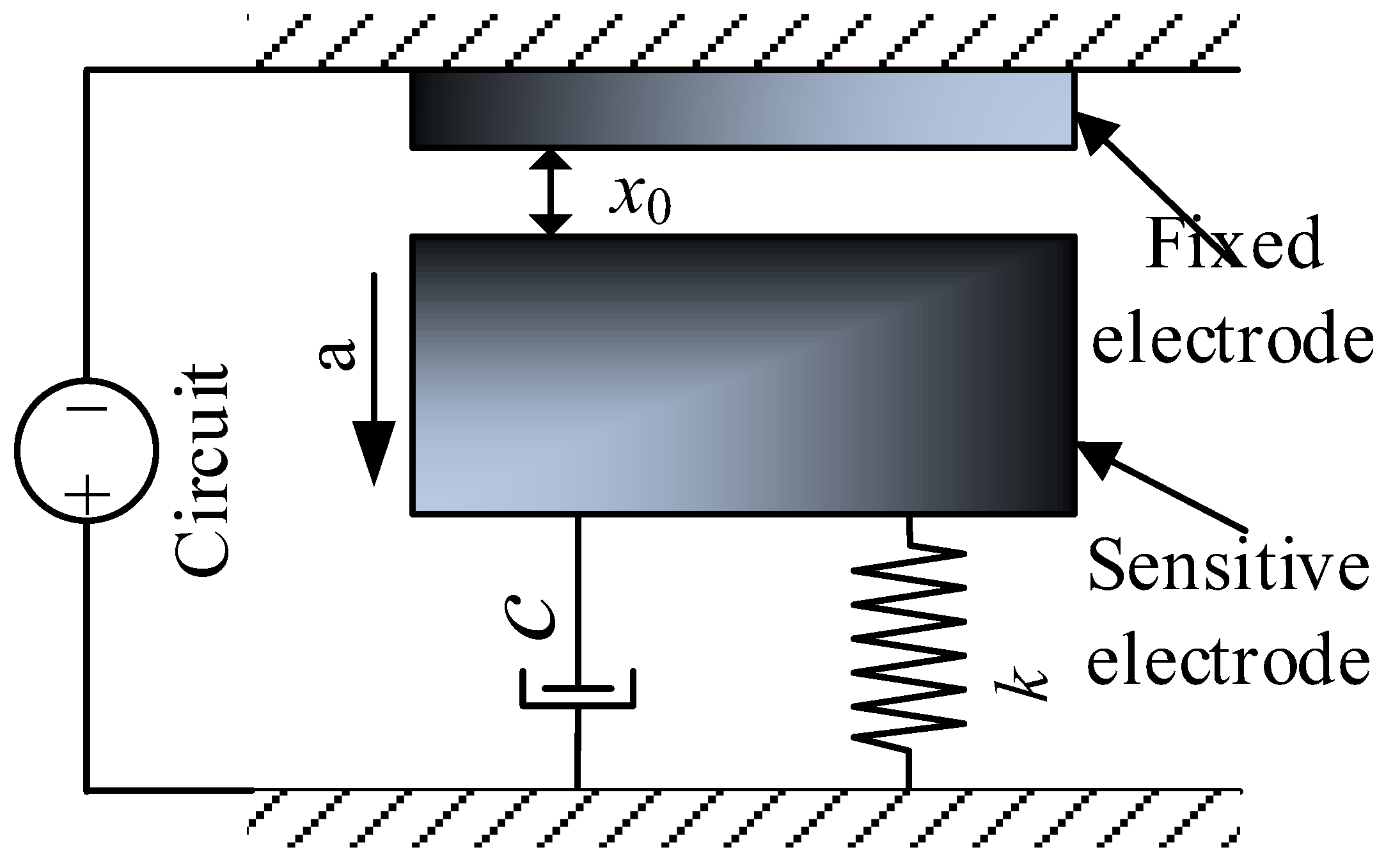
Figure 2.
The inertial switch structure schematic diagram: (a) 3D view, (b) top view, (c) side view, (d) partial magnification view.
Figure 2.
The inertial switch structure schematic diagram: (a) 3D view, (b) top view, (c) side view, (d) partial magnification view.
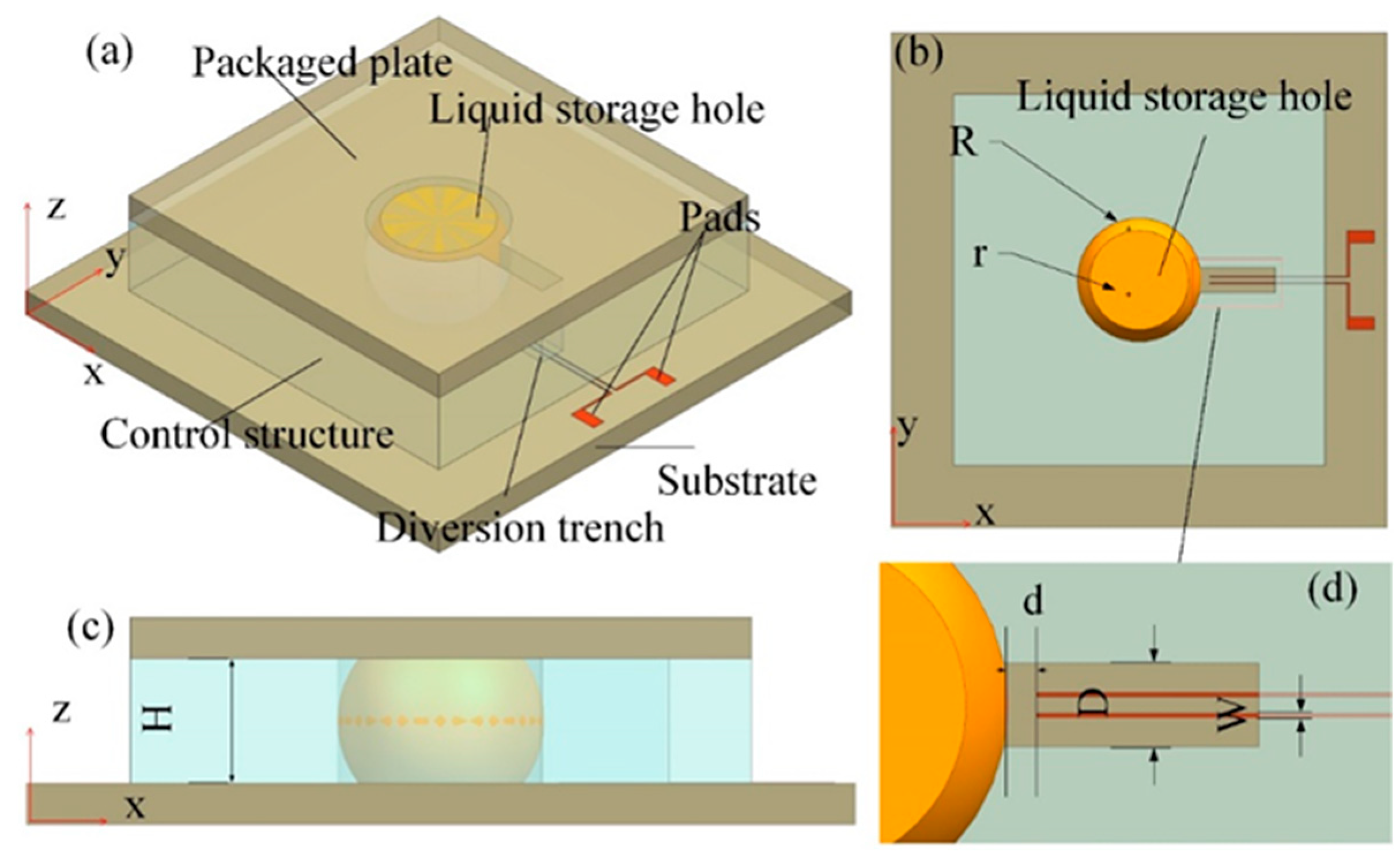
Figure 3.
Schematic diagram of the response process of mercury droplets.
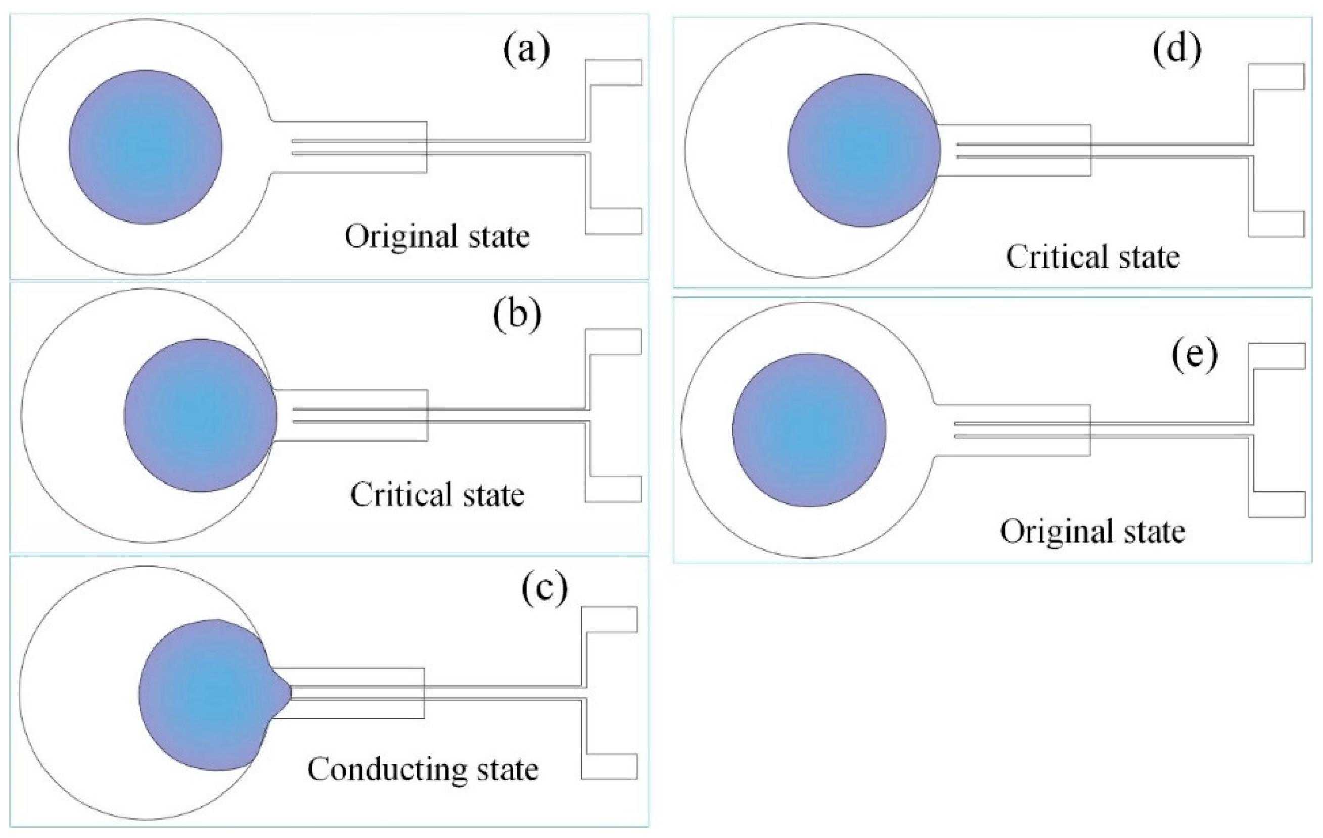
Figure 4.
Schematic diagram of the preparation process.
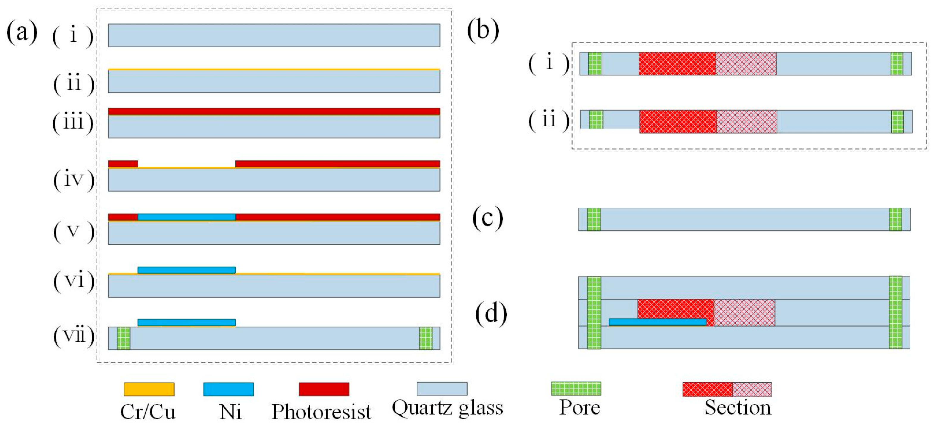
Figure 5.
The fabricated prototype of inertial switch.
Figure 6.
(a) Schematic diagram of the test principle, (b) Test setup Photos.
Figure 7.
(a) The tested results of threshold acceleration, (b) the enlargement diagram of dynamic contact process, (c) The threshold acceleration results obtained from the digital acceleration sensor test.
Figure 7.
(a) The tested results of threshold acceleration, (b) the enlargement diagram of dynamic contact process, (c) The threshold acceleration results obtained from the digital acceleration sensor test.
Figure 8.
(a) Contact signals of the inertial switch under overload acceleration, (b) the enlargement diagram of dynamic contact process.
Figure 8.
(a) Contact signals of the inertial switch under overload acceleration, (b) the enlargement diagram of dynamic contact process.
Figure 9.
Diagram of the movement state of metal droplets. (a) critical state, (b) conductive state, (c) overload state, (d) recovery to conductive state, (e) critical state.
Figure 9.
Diagram of the movement state of metal droplets. (a) critical state, (b) conductive state, (c) overload state, (d) recovery to conductive state, (e) critical state.
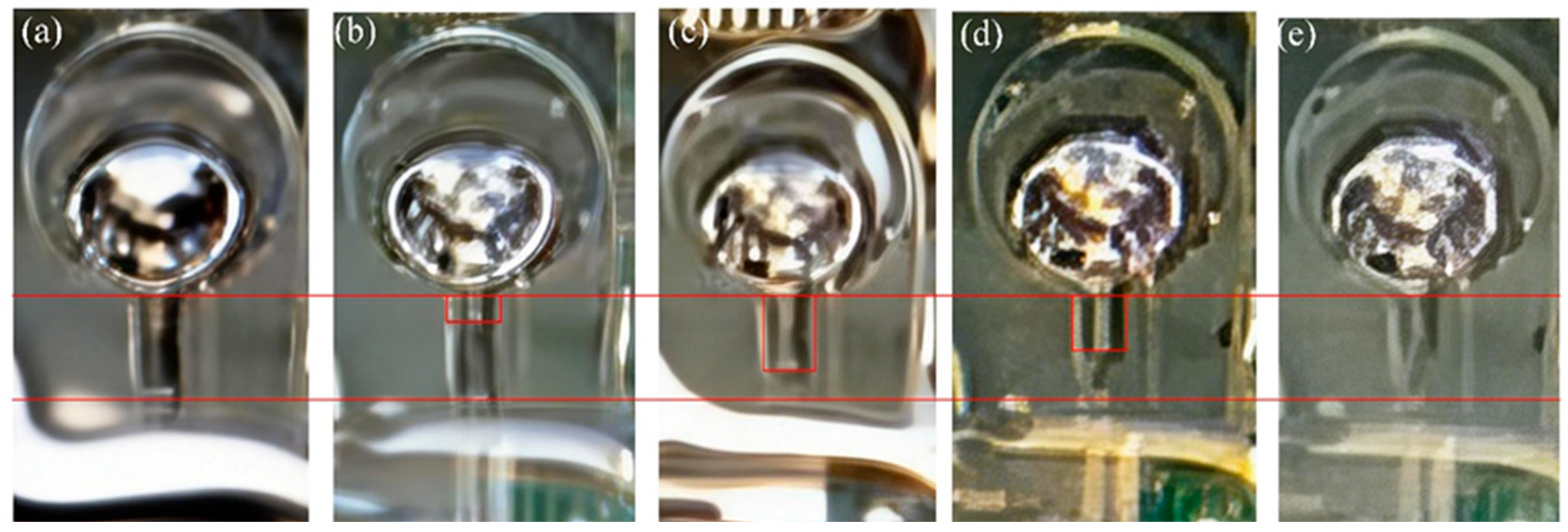

Table 1.
List of structural parameters of designed inertial switch.
| Structure | Control structure | Fixed electrode | droplets | |||
| Paramenter | R | H | D | W | d | r |
| Values(mm) | 2.5 | 3.0 | 1.0 | 0.05 | 0.2 | 2.5 |
Disclaimer/Publisher’s Note: The statements, opinions and data contained in all publications are solely those of the individual author(s) and contributor(s) and not of MDPI and/or the editor(s). MDPI and/or the editor(s) disclaim responsibility for any injury to people or property resulting from any ideas, methods, instructions or products referred to in the content. |
© 2026 by the authors. Licensee MDPI, Basel, Switzerland. This article is an open access article distributed under the terms and conditions of the Creative Commons Attribution (CC BY) license (http://creativecommons.org/licenses/by/4.0/).
Copyright: This open access article is published under a Creative Commons CC BY 4.0 license, which permit the free download, distribution, and reuse, provided that the author and preprint are cited in any reuse.


