
Submitted:
16 January 2026
Posted:
19 January 2026
You are already at the latest version
Abstract
Standing equine cone-beam CT (CBCT) enables diagnostic imaging in weight-bearing conditions, reducing the need for general anaesthesia, but residual postural sway during acquisition can introduce motion artefacts that degrade image quality. External optical tracking based on a ChArUco fiducial and an auxiliary RGB camera is a practical strategy for projection-wise motion compensation; however, the impact of camera--marker geometry on pose-estimation performance is not well characterised. This study evaluates how viewing angle and working distance affect ChArUco-based pose estimation in a controlled CBCT-motivated setting. Pose estimates were obtained with an Intel RealSense D435 RGB sensor and OpenCV, using dedicated mechanical fixtures to vary viewing angle in 1° increments and to adjust the camera-to-board distance in 5cm steps. Accuracy and precision were quantified using mean absolute error with respect to ground truth and the standard deviation across repeated measurements. Continuous and cyclic acquisition protocols yielded comparable errors, indicating that repeated repositioning did not introduce substantial additional variability. Viewing-angle experiments revealed a consistent accuracy--precision trade-off for rotation estimation: frontal views minimise mean absolute error but exhibit the highest variability, whereas increasingly oblique views reduce variability at the expense of larger mean error. Increasing working distance was associated with larger standard deviations, particularly affecting depth repeatability. These results provide practical guidance for selecting camera placement and nominal viewpoints when deploying ChArUco-based tracking for motion-aware standing equine CBCT/CT workflows.
Keywords:
CBCT
; Equine
; ArUco
; ChArUco
; pose estimation
1. Introduction
Computer Vision (CV) focuses on the automatic extraction, analysis, and interpretation of meaningful information from single images or sequences of images, and relies on theoretical frameworks and algorithms for autonomous visual understanding [1]. A long-standing challenge concerns three-dimensional (3D) reconstruction from two-dimensional (2D) images, which arises in multiple domains—robotics [2,3], medicine [4,5], and virtual reality [6,7]—and stems from the loss of depth information when projecting a 3D scene onto the image plane (). Approaches such as photogrammetry, stereo vision (SV), and structure-from-motion (SfM) address this task by detecting distinctive features (keypoints), establishing correspondences across views, and combining image evidence with camera parameters to infer 3D coordinates for scene points.
In many of these pipelines, accurate and stable camera pose estimation is a key determinant of reconstruction quality. Physical fiducials with known geometry are widely used to stabilise pose: ArUco markers [8,9] offer robust, uniquely identifiable square patterns but limited corner refinement; chessboards enable subpixel-accurate corner localisation yet require full visibility and are less tolerant to occlusions [10,11]. ChArUco boards combine these strengths by embedding ArUco markers within a chessboard grid, achieving reliable detection under partial occlusion together with high-precision corner refinement via interpolated chessboard corners [11]. Thanks to the known layout, a single image suffices to estimate the rigid transformation between camera and board, typically decomposed into rotation (yaw, pitch, roll) and position components (, , ).
A setting where precise, projection-wise pose tracking is particularly valuable is CBCT (or CT) of standing horses. Dedicated systems for standing acquisitions of the head and distal limbs allow imaging of sedated equine patients in a weight-bearing position, avoiding the risks of general anaesthesia while preserving diagnostic performance [12,13,14,15,16]. However, residual postural sway during gantry rotation induces view-inconsistent motion that manifests as blur and streak artifacts and may reduce confidence in the assessment of fine osseous detail [14,15]. To mitigate such motion, previous work has mainly relied on mechanical restraints and acquisition protocols, while software-based motion compensation is still uncommon in routine equine imaging and lacks quantitative design guidelines.
By contrast, in human CT and CBCT, several prototype systems already exploit external motion sensing for projection-wise motion correction. Optical trackers, inertial sensors, and RGB-D cameras have been used to monitor patient motion during helical or cone-beam scans and to warp the projections accordingly, recovering image quality that approaches that of motion-free acquisitions [17,18,19]. Low-cost Intel RealSense devices in particular have been characterised for clinical motion tracking and CT perfusion motion correction, showing millimetric pose accuracy in realistic scanner environments [20,21,22]. These developments motivate the use of compact RGB or RGB-D modules as external motion sensors in standing equine CT/CBCT workflows.
As shown in Figure 1, a practical strategy is to rigidly mount a lightweight ChArUco board near the region of interest and observe it with an auxiliary RGB camera during acquisition. Each frame provides a board pose that, via a fixed extrinsic calibration to the scanner, can be mapped to object motion for projection-wise motion compensation. In this context, the camera–marker geometry—specifically, viewing angle and working distance—directly affects both pose accuracy (bias w.r.t. ground truth) and pose precision (variance/noise), and thus the effectiveness of motion correction.
Although ChArUco boards are already adopted across diverse applications—e.g., RGB-D fusion [23], omnidirectional camera calibration [24], and robust detection in challenging conditions [25]—the quantitative relationship between pose-estimation accuracy/precision and the relative camera–board configuration remains underexplored. In particular, there is limited evidence on how viewing angle and camera-to-plane distance shape the error w.r.t. a known ground truth and the noise of estimated rotations and positions, despite the practical impact on reconstruction quality in motion-aware workflows and on the design of standing equine CT/CBCT setups.
The present study addresses this gap through a controlled experimental analysis that systematically varies camera-to-plane angles and camera-to-plane positions, acquiring repeated measurements to characterise how pose accuracy and precision change with viewpoint. The resulting trends are then interpreted as actionable guidance for standing equine CBCT/CT deployments.
2. Materials and Methods
This section describes the apparatus and processing workflow used to quantify the impact of camera–marker geometry on pose-estimation accuracy and precision in a standing equine, CBCT-motivated experimental setting. The following subsections detail the ChArUco board, the RGB camera, the mechanical setup enabling controlled variations in camera-to-plane angle and position, and the camera pose-estimation procedure.
2.1. ChArUco Board
The ChArUco board used in this study, shown in Figure 2a, consists of a 7×7 chessboard grid with 24 unique ArUco markers placed inside the white squares. Each chessboard square measures 15 mm per side, while each ArUco marker measures 10 mm per side. The relative pose between the camera and the board was parameterised by five scalar quantities:
- Camera-to-plane angles ():, where is the angle between the camera optical axis () and the board normal vector , and is the in-plane rotation around .
- Camera-to-plane positions ():, describing the position of the board origin expressed in the camera reference system.
To improve clarity, parameters defining both and are depicted in Figure 2b.
Both the detection of the ChArUco board and the camera pose estimation were performed using the open-source OpenCV library [26], in conjunction with the Qt Creator development environment (version 5.12.6) and the C++ programming language.
2.2. RGB Camera
The RGB camera employed in this study is the RGB module of the Intel RealSense D435 3D camera. Its key specifications are summarised in Table 1.
2.3. Mechanical Systems for Camera or ChArUco Handling
Once rigidly attached to the horse, the ChArUco target is expected to undergo predominantly translational excursion (towards/away from the observing camera) and changes in viewing angle , rather than in-plane rotation about the board normal. This reflects the residual postural sway of the sedated standing subject around its resting stance.
Thus, the experimental setups were designed to independently vary either the viewing-angle or the position along the z-axis between the ChArUco board and the camera, while monitoring the remaining pose parameters to verify that off-axis positions and remained negligible:
- Viewing angle setup: as shown in Figure 3a, this setup consists of a steel mechanical wheel that rotates precisely about its axis in increments and is driven by a stepper motor. Two orthogonal grooves intersecting at the wheel’s centre enable precise placement of the ChArUco board such that its coordinate origin coincides with the wheel’s axis of rotation. This alignment is critical to minimise undesired translational components and rotation about during wheel motion.
- position setup: as shown in Figure 3b, this setup uses a 1-meter-long steel rail with a central horizontal groove. The ChArUco board is fixed to an L-shaped bracket and mounted orthogonally at one end of the base. The camera is attached to a separate L-shaped bracket and positioned to face the ChArUco board. By sliding the bracket along the groove, the distance between the camera and the ChArUco board is adjusted along the z-axis while minimising off-axis motion.
For the viewing-angle experiments, the wheel was controlled via its dedicated software, which allowed setting angular positions in 1° increments with respect to a reference configuration defined as . Accordingly, the ground-truth rotation was taken as the wheel angle set in the control software. To reduce the effect of mechanical backlash, target angles were approached consistently using the same rotation direction.
For the distance experiments, the ground-truth camera-to-plane distance was measured using a ruler. Measurements were taken between the camera reference point and the ChArUco board plane (as defined in Figure 2b) at each tested position, and recorded with the ruler resolution.
Pose accuracy was quantified as the absolute error with respect to ground truth, e.g. and , while precision was quantified as the variability (e.g., standard deviation) across repeated measurements under identical conditions.
2.4. Measurements Acquisition Procedure
Multiple tests were conducted to evaluate the accuracy of camera pose estimation relative to the ChArUco marker. In each test, the camera was initially positioned relative to the ChArUco board, and the pose parameters and were acquired.
Before each run, an initial reference pose was recorded at the start position: and . These reference values were subtracted from each subsequent measurement to describe rotation/position increments rather than absolute pose. Repeatability and drift were quantified across repeated runs using statistics of these relative pose trajectories. Absolute accuracy was also evaluated as the error with respect to the known ground truth defined for each test.
2.4.1. Continuous and Cyclic Acquisitions
The first experiment aimed to assess the noise introduced by the camera and by the mechanical movement system. For this test, the camera was fixed at a distance of = 40 cm from the ChArUco board, and the viewing angle was varied using the mechanical wheel. The tested angles were: [, , , , , , ], using two acquisition methods:
- Continuous acquisitions: to evaluate noise introduced solely by the camera, each pose was estimated ten times at each angle before rotating the wheel to the next angle.
- Cyclic acquisitions: to assess the influence of the mechanical system, only one pose was estimated at each angle. After reaching , the wheel was rotated back to in a single motion, and the process was repeated ten times in total.
After each acquisition, the standard deviation of all five pose parameters was computed to compare the consistency of the two acquisition approaches.
This comparison is motivated by projection-wise motion tracking in CT/CBCT: during an acquisition, the tracker delivers one pose estimate per projection while the gantry (or the object) moves between successive views. “Continuous” acquisitions isolate the intrinsic measurement noise of the camera/estimator at a fixed viewpoint (no repositioning). “Cyclic” acquisitions mimic repeated view-by-view sampling across angles and re-positioning, therefore capturing additional variability introduced by the mechanical motion (e.g., backlash, settling, and repeatability of the rotation wheel), which is analogous to view-to-view perturbations during a CBCT sweep.
2.4.2. Viewing Angle Variation
The second experiment evaluated how viewing angle estimation accuracy varies with the viewing angle. Angles ranging from to were tested: [, , , , , , , , , , , , , , ]. The ChArUco board was aligned with the rotation axis of the mechanical wheel, and the camera was placed at fixed distances of = 40 cm and = 60 cm. At each angle and distance, twenty pose estimations were acquired to ensure statistical robustness.
2.4.3. Z-Axis Position Variation
The third experiment focused on how the position along the z-axis affects the estimation of the parameter. Camera poses were estimated at distances ranging from = 25 cm to = 60 cm, in 5 cm increments ( = 5 cm). As in the previous test, each position was measured twenty times to support statistical analysis.
3. Results
In the following subsections, the results for each of the three conducted tests will be presented.
In all bar plots, bar height represents the mean absolute error with respect to ground truth, while error bars indicate the standard deviation across repeated measurements under the same condition.
3.1. Continuous vs. Cyclic Acquisition
The results of this test are reported in Figure 4 and Figure 5. Figure 4a,b show the mean absolute errors of the parameters for the continuous and cyclic protocols, respectively. Figure 5a,b show the corresponding mean absolute errors for the parameters.
The mechanical wheel provided controlled viewpoint changes in 1° increments through stepper-motor actuation. The comparison between continuous and cyclic acquisitions was used to verify that repeated repositioning of the wheel does not introduce additional variability beyond the intrinsic pose-estimation noise. As shown in Figure 4 and Figure 5, the two protocols yield comparable absolute errors across the tested angles, indicating good repeatability of the mechanical wheel under the adopted operating conditions.
Therefore, since the two protocols exhibited comparable pose-estimation performance, subsequent experiments are reported using the continuous acquisition method only.
3.2. Influence of Viewing Angle on Pose Estimation
The results of this test are reported in Figure 6 and Figure 7. Figure 6a,b show the mean absolute errors of the parameters at fixed working distances cm and cm, respectively. Figure 7a,b show the corresponding mean absolute errors for the parameters at the same distances.
Across viewing angles, the mean absolute error on is minimal in the frontal configuration () and increases progressively at more oblique views. Conversely, the standard deviation (error bars) is highest at and decreases as the viewing angle departs from frontal, indicating a trade-off between accuracy (lower mean absolute error) and precision (lower variability). A similar behaviour is observed for the in-plane rotation . Comparing working distances, moving from to yields lower mean absolute errors (lower bars) but larger standard deviations (higher error bars) for both and . Notably, the angle-dependent trend in variability is preserved at both distances, with the largest standard deviations near the frontal configuration and decreasing variability at increasing obliquity.
3.3. Influence of Distance on Pose Estimation
The results of this test are presented in Figure 8. In Figure 8a, the average errors related to parameters are presented, while in Figure 8b, the average errors related to parameters are presented.
Across the tested working distances, the lateral position components and exhibit very low standard deviation, and their mean absolute errors fluctuate without a clear distance-dependent trend. By contrast, for the depth component , the mean absolute error does not show a systematic trend with distance. In contrast, the standard deviation increases markedly as the camera-to-ChArUco distance grows. Overall, these results indicate that increasing working distance primarily reduces the repeatability of estimation, even when the average agreement with ground truth remains comparable.
4. Discussion
The primary objective of this study was to assess how camera–marker geometry affects the reliability of ChArUco-based pose estimation, with a specific focus on conditions relevant to standing equine CBCT/CT. Overall, the experiments highlight that geometric choices can induce distinct and sometimes opposing effects on accuracy, quantified here via mean absolute error with respect to ground truth, and precision (repeatability), quantified via the standard deviation across repeated estimates.
The first test compared continuous and cyclic acquisition protocols to verify whether repeated mechanical repositioning of the mechanical wheel introduces additional variability beyond the intrinsic pose-estimation noise. The results, shown in Figure 4 and Figure 5, exhibit comparable mean absolute errors and comparable trends for both rotation ( – Figure 4a,b) and position ( – Figure 5a,b) parameters across the tested angles, indicating good repeatability of the mechanical wheel under the adopted operating conditions. Minor differences at specific angles (e.g., near the frontal configuration), or the increasing trend of the parameter, are consistent with small setup-dependent effects, such as slight misalignment between the camera image plane and the board plane, or small offsets in the positioning of the board reference frame with respect to the rotation axis. These findings support the validity of the subsequent analyses performed using the continuous protocol only, which also simplifies both the experimental workflow and results presentation.
The second test investigated how rotation-estimation performance changes as the viewing angle varies, mimicking the angular component of postural sway during standing acquisitions. To assess that, the setup shown in Figure 3a was adopted, and the obtained results are shown in Figure 6 and Figure 7. A consistent trade-off between accuracy and precision was observed. For both working distances ( and ), the mean absolute error on the viewing angle is minimal in the frontal configuration () and increases progressively at more oblique views. Conversely, the standard deviation (error bars) is highest at and decreases as the viewing angle departs from frontal, indicating that frontal viewing yields the smallest average error but also the largest measurement variability, whereas moderately oblique views provide more repeatable estimates at the expense of increased average error. A similar behaviour is observed for the in-plane rotation . When comparing working distances, moving from to yields lower mean absolute errors (lower bars) but larger standard deviations (higher error bars) for both and . A plausible explanation is that increasing distance reduces the impact of residual lens-distortion and near-field geometric effects (improving average agreement), while simultaneously reducing the board’s footprint in the RGB image (decreasing corner/marker sampling and increasing frame-to-frame variability). Importantly, the angle-dependent trend in variability is preserved at both distances, with maximum variability around the frontal configuration and decreasing variability at higher obliquity. Although this test primarily targeted the variability of the rotation parameters (), the position components () were also recorded. The corresponding results exhibit qualitatively similar angle-dependent behaviour; however, increasing the working distance from to leads to both higher mean absolute errors and larger standard deviations for the parameters, suggesting an overall degradation of position-estimation performance at the longer distance.
The third test evaluated the effect of working distance on position estimation, mimicking small approach/withdrawal components of motion around a resting position. To assess that, the setup shown in Figure 3b was adopted, and the obtained results are shown in Figure 8. While and exhibit very low standard deviation across all tested distances (and mean absolute errors that fluctuate without a clear distance-dependent trend), the parameter under test, , shows a marked increase in standard deviation as the camera-to-board distance increases. Notably, the mean absolute error of does not exhibit a strong monotonic trend with distance in the explored range; however, the reduced repeatability at larger distances indicates that depth estimation becomes increasingly sensitive to pixel-level noise and corner localisation uncertainty when the board occupies fewer pixels in the image. Although this test primarily targeted the variability of the position parameters (), the rotation components () were also recorded. The corresponding results exhibit both higher mean absolute errors and larger standard deviations for the parameters, suggesting an overall degradation of rotation-estimation performance at the longer distance.
In standing equine CBCT/CT, residual sway during gantry rotation introduces view-inconsistent motion that can manifest as blur or streaking in the reconstructed volume. A practical mitigation strategy is to rigidly mount a lightweight ChArUco board on the horse and observe it with a synchronised camera; via extrinsic calibration to the scanner, each detected pose can provide a per-projection motion estimate for motion-compensated reconstruction. In this context, precision (low frame-to-frame variability) is often a critical factor: even small jitter in pose estimates can propagate into projection-domain corrections and limit the achievable reduction of residual blur. The observed accuracy–precision trade-off suggests that a geometry optimised for minimal mean error (frontal view) may not be optimal for minimal pose noise. A practical implication is to avoid operating exactly at the frontal configuration when repeatability is prioritised; instead, a moderately oblique nominal viewing configuration may reduce variability across repeated estimates, provided that the associated increase in mean absolute error remains acceptable for the application. At the same time, the working distance should be selected to keep the board sufficiently large in the RGB image, since increasing the distance was found to degrade repeatability.
Despite the encouraging results, several limitations should be acknowledged. First, the experiments were performed under controlled laboratory conditions using a single board layout and a single RGB sensor. Real deployments may involve varying illumination, partial occlusions by staff or equipment, specularities, and motion patterns that combine rotations and translations along multiple axes. Second, only limited geometric degrees of freedom were explored (single-axis rotations and axial distance changes); future work should extend the analysis to multi-axis rotations and more complex trajectories, better approximating realistic sway during acquisition. Finally, this work focused on pose-estimation performance metrics rather than image-quality outcomes. Future validation should include motion-compensated reconstructions in realistic scanner environments (ideally in vivo) to quantify improvements in image sharpness and reduction of streak artefacts as a function of the chosen camera–marker geometry. Extensions may also include testing different ChArUco scales, multi-camera fusion, and the integration of RGB-D information where available.
5. Conclusions
This study investigated how camera–ChArUco geometry influences the performance of marker-based pose estimation in a context motivated by motion compensation for standing equine CBCT/CT. Using controlled experiments with known ground truth, the effects of acquisition protocol, viewing angle, and working distance were analysed in terms of both accuracy (mean absolute error) and precision (repeatability, quantified by the standard deviation across repeated estimates). First, continuous and cyclic acquisition protocols yielded comparable performance, indicating that repeated repositioning of the mechanical wheel did not introduce substantial additional variability under the adopted operating conditions. Second, viewing-angle experiments revealed a consistent accuracy–precision trade-off for rotation estimation: frontal views minimise the mean absolute error, whereas increasingly oblique views reduce variability (jitter) at the cost of larger mean errors. In addition, increasing the working distance from to reduced the mean absolute rotation error but increased variability. Third, distance experiments showed that lateral positions (, ) remain stable across distances, whereas the depth component exhibits a marked increase in standard deviation at larger working distances, despite the absence of a clear monotonic trend in mean absolute error. Overall, these findings suggest that camera placement for external motion tracking should be selected according to the relative importance of bias versus repeatability for the intended motion-compensation pipeline: a strictly frontal configuration is not necessarily optimal when low frame-to-frame variability is prioritised, and excessive working distances should be avoided to preserve repeatable depth estimation. Future work will validate these conclusions in realistic scanner environments by integrating the tracking pipeline with motion-compensated reconstruction and quantifying the resulting improvements in image quality.
Author Contributions
Conceptualization, C.A. and L.B.; methodology, C.A. and L.B.; software, C.A.; validation, C.L.B., P.F. and L.B.; investigation, C.A.; resources, C.L.B. and L.B.; data curation, C.A.; writing—original draft preparation, C.A.; writing—review and editing, C.A., C.L.B., P.F. and L.B.; visualization, C.A.; supervision, C.L.B., P.F. and L.B.; project administration, L.B. All authors have read and agreed to the published version of the manuscript.
Funding
This research received no external funding.
Institutional Review Board Statement
Not applicable.
Informed Consent Statement
Not applicable.
Data Availability Statement
The data presented in this study are available on request from the corresponding author due to legal reasons.
Conflicts of Interest
The authors declare no conflicts of interest.
References
- Klette, R. Concise computer vision; Vol. 233, Springer, 2014.
- Fazakas, T.; Fekete, R.T. 3D reconstruction system for autonomous robot navigation. 2010 11th International Symposium on Computational Intelligence and Informatics (CINTI) 2010, pp. 267–270.
- Tang, Y.; Chen, M.; Wang, C.; Luo, L.; Li, J.; Lian, G.; Zou, X. Recognition and localization methods for vision-based fruit picking robots: A review. Frontiers in Plant Science 2020, 11, 510.
- Huang, Y.; Qiu, Z.; Song, Z. 3D reconstruction and visualization from 2D CT images. 2011 IEEE International Symposium on IT in Medicine and Education 2011, 2, 153–157.
- Rengier, F.; Mehndiratta, A.; Von Tengg-Kobligk, H.; Zechmann, C.M.; Unterhinninghofen, R.; Kauczor, H.U.; Giesel, F.L. 3D printing based on imaging data: review of medical applications. International journal of computer assisted radiology and surgery 2010, 5, 335–341.
- Ebner, T.; Feldmann, I.; Renault, S.; Schreer, O.; Eisert, P. Multi-view reconstruction of dynamic real-world objects and their integration in augmented and virtual reality applications. Journal of the Society for Information Display 2017, 25, 151–157.
- Tang, F.; Wu, Y.; Hou, X.; Ling, H. 3D mapping and 6D pose computation for real time augmented reality on cylindrical objects. IEEE Transactions on Circuits and Systems for Video Technology 2019, 30, 2887–2899.
- Romero-Ramirez, F.J.; Muñoz-Salinas, R.; Medina-Carnicer, R. Speeded up detection of squared fiducial markers. Image and vision Computing 2018, 76, 38–47.
- Garrido-Jurado, S.; Munoz-Salinas, R.; Madrid-Cuevas, F.J.; Medina-Carnicer, R. Generation of fiducial marker dictionaries using mixed integer linear programming. Pattern recognition 2016, 51, 481–491.
- De la Escalera, A.; Armingol, J.M. Automatic chessboard detection for intrinsic and extrinsic camera parameter calibration. Sensors 2010, 10, 2027–2044.
- ChArUco marker detection, 2024. Last access: 02/02/2024.
- Dakin, S.; Lam, R.; Rees, E.; Mumby, C.; West, C.; Weller, R. Technical set-up and radiation exposure for standing computed tomography of the equine head. Equine Veterinary Education 2014, 26, 208–215.
- Davies, T.; Skelly, C.; Puggioni, A.; D’Helft, C.; Connolly, S.; Hoey, S. Standing CT of the equine head: reducing radiation dose maintains image quality. Veterinary Radiology & Ultrasound 2020, 61, 137–146.
- Mathee, N.; Robert, M.; Higgerty, S.M.; Fosgate, G.T.; Rogers, A.L.; d’Ablon, X.; Carstens, A. Computed tomographic evaluation of the distal limb in the standing sedated horse: Technique, imaging diagnoses, feasibility, and artifacts. Veterinary Radiology & Ultrasound 2023, 64, 243–252.
- Pauwels, F.E.; Van der Vekens, E.; Christan, Y.; Koch, C.; Schweizer, D. Feasibility, indications, and radiographically confirmed diagnoses of standing extremity cone beam computed tomography in the horse. Veterinary Surgery 2021, 50, 365–374.
- Gaida, J.L.; Steinberg, T.; Stieger-Vanegas, S.M.; Merle, R.; Lischer, C.J. Equine Standing Multidetector Computed Tomography of the Distal Thoracic Limb and Tarsus Has a Lower Cumulative Radiation Dose than Digital Radiography. Veterinary Radiology & Ultrasound 2025, 66, e70049.
- Kim, J.; Nuyts, J.; Kyme, A.; Kuncic, Z.; Fulton, R. A rigid motion correction method for helical computed tomography (CT). Physics in Medicine & Biology 2015, 60, 2047.
- Brombal, L.; Arana Peña, L.M.; Arfelli, F.; Longo, R.; Brun, F.; Contillo, A.; Di Lillo, F.; Tromba, G.; Di Trapani, V.; Donato, S.; et al. Motion artifacts assessment and correction using optical tracking in synchrotron radiation breast CT. Medical Physics 2021, 48, 5343–5355.
- Maier, J.; Nitschke, M.; Choi, J.H.; Gold, G.; Fahrig, R.; Eskofier, B.M.; Maier, A. Rigid and non-rigid motion compensation in weight-bearing CBCT of the knee using simulated inertial measurements. IEEE Transactions on Biomedical Engineering 2021, 69, 1608–1619.
- Siena, F.L.; Byrom, B.; Watts, P.; Breedon, P. Utilising the intel realsense camera for measuring health outcomes in clinical research. Journal of medical systems 2018, 42, 53.
- House, R.; Lasso, A.; Harish, V.; Baum, Z.; Fichtinger, G. Evaluation of the Intel RealSense SR300 camera for image-guided interventions and application in vertebral level localization. In Proceedings of the Medical Imaging 2017: Image-Guided Procedures, Robotic Interventions, and Modeling. SPIE, 2017, Vol. 10135, pp. 771–777.
- Moghari, M.D.; Noonan, P.; Henry, D.; Fulton, R.R.; Young, N.; Moore, K.; Evanns, A.; Kyme, A. Characterisation of the Intel RealSense D415 Stereo Depth Camera for Motion-Corrected CT Perfusion Imaging. arXiv preprint arXiv:2403.16490 2024.
- de Medeiros Esper, I.; Smolkin, O.; Manko, M.; Popov, A.; From, P.J.; Mason, A. Evaluation of RGB-D Multi-Camera Pose Estimation for 3D Reconstruction. Applied Sciences 2022, 12. [CrossRef]
- An, G.H.; Lee, S.; Seo, M.W.; Yun, K.; Cheong, W.S.; Kang, S.J. Charuco Board-Based Omnidirectional Camera Calibration Method. Electronics 2018, 7. [CrossRef]
- Hu, D.; DeTone, D.; Malisiewicz, T. Deep charuco: Dark charuco marker pose estimation. In Proceedings of the Proceedings of the IEEE/CVF Conference on computer vision and pattern recognition, 2019, pp. 8436–8444.
- OpenCV: Open Source Computer Vision Library, 2024. Last access: 02/02/2024.
Figure 1.
Sedated horse positioned for standing equine CBCT of the head region. A ChArUco board is rigidly attached to the horse’s head and observed by the RGB camera for external pose tracking during acquisition.
Figure 1.
Sedated horse positioned for standing equine CBCT of the head region. A ChArUco board is rigidly attached to the horse’s head and observed by the RGB camera for external pose tracking during acquisition.
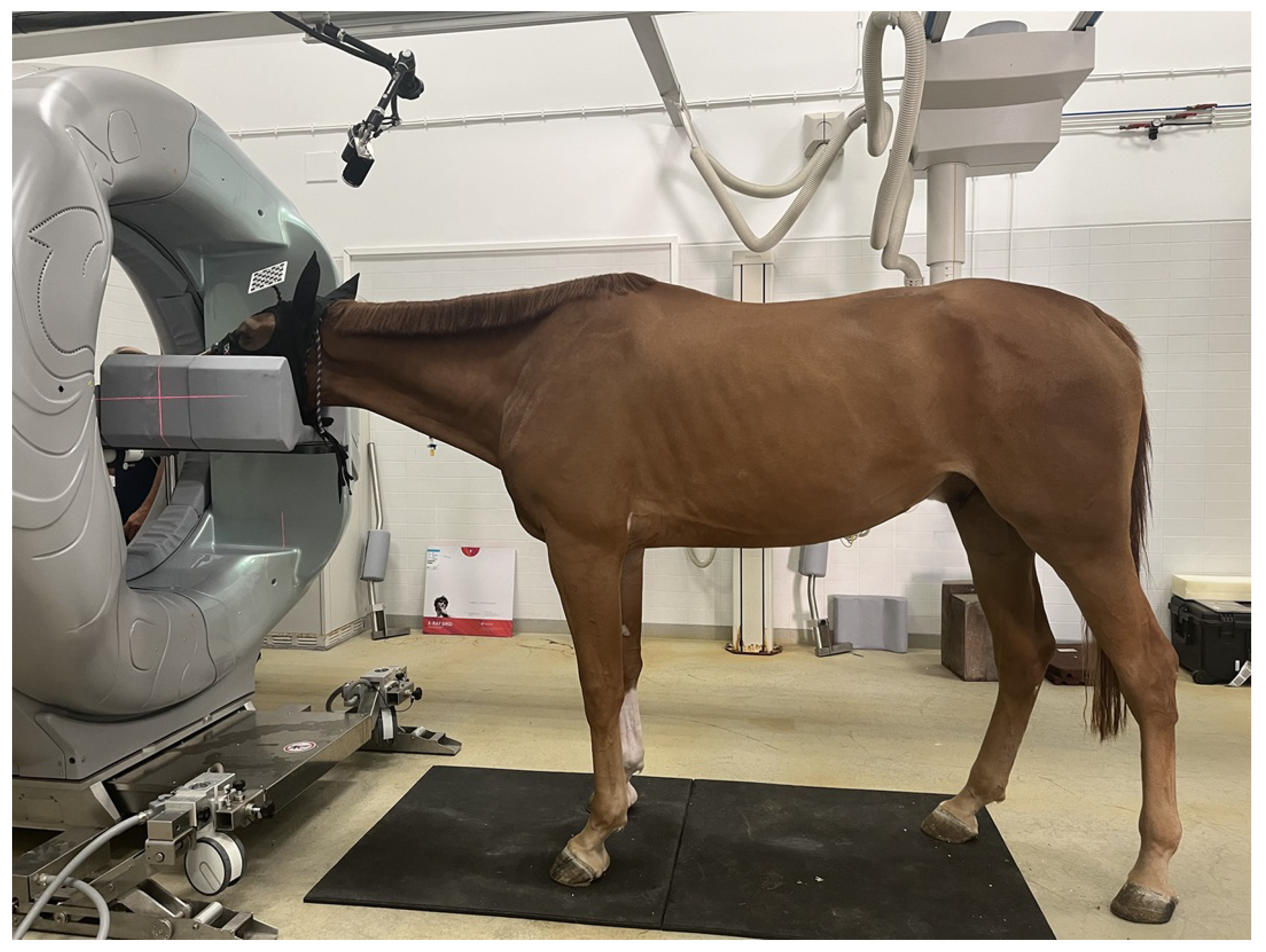
Figure 2.
(a) ChArUco board used during the experiments. (b) Camera and ChArUco reference systems and definition of and . ChArUco’s origin is expressed in the camera reference system.
Figure 2.
(a) ChArUco board used during the experiments. (b) Camera and ChArUco reference systems and definition of and . ChArUco’s origin is expressed in the camera reference system.
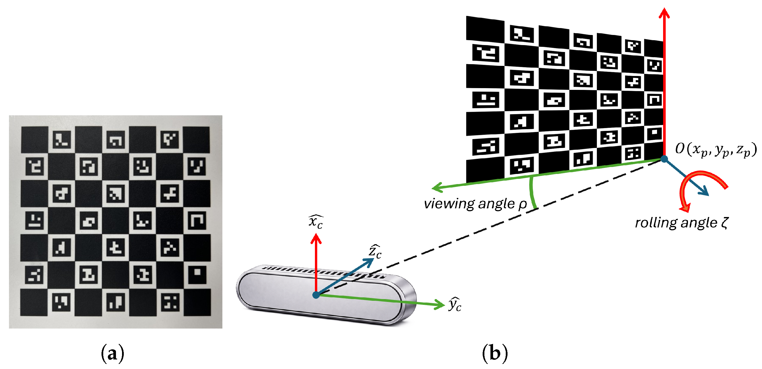
Figure 3.
(a) Setup used during the test for the evaluation of the viewing angle parameter. The camera was placed on a tripod to ensure stability. (b) Setup used during the test for the evaluation of the parameter.
Figure 3.
(a) Setup used during the test for the evaluation of the viewing angle parameter. The camera was placed on a tripod to ensure stability. (b) Setup used during the test for the evaluation of the parameter.
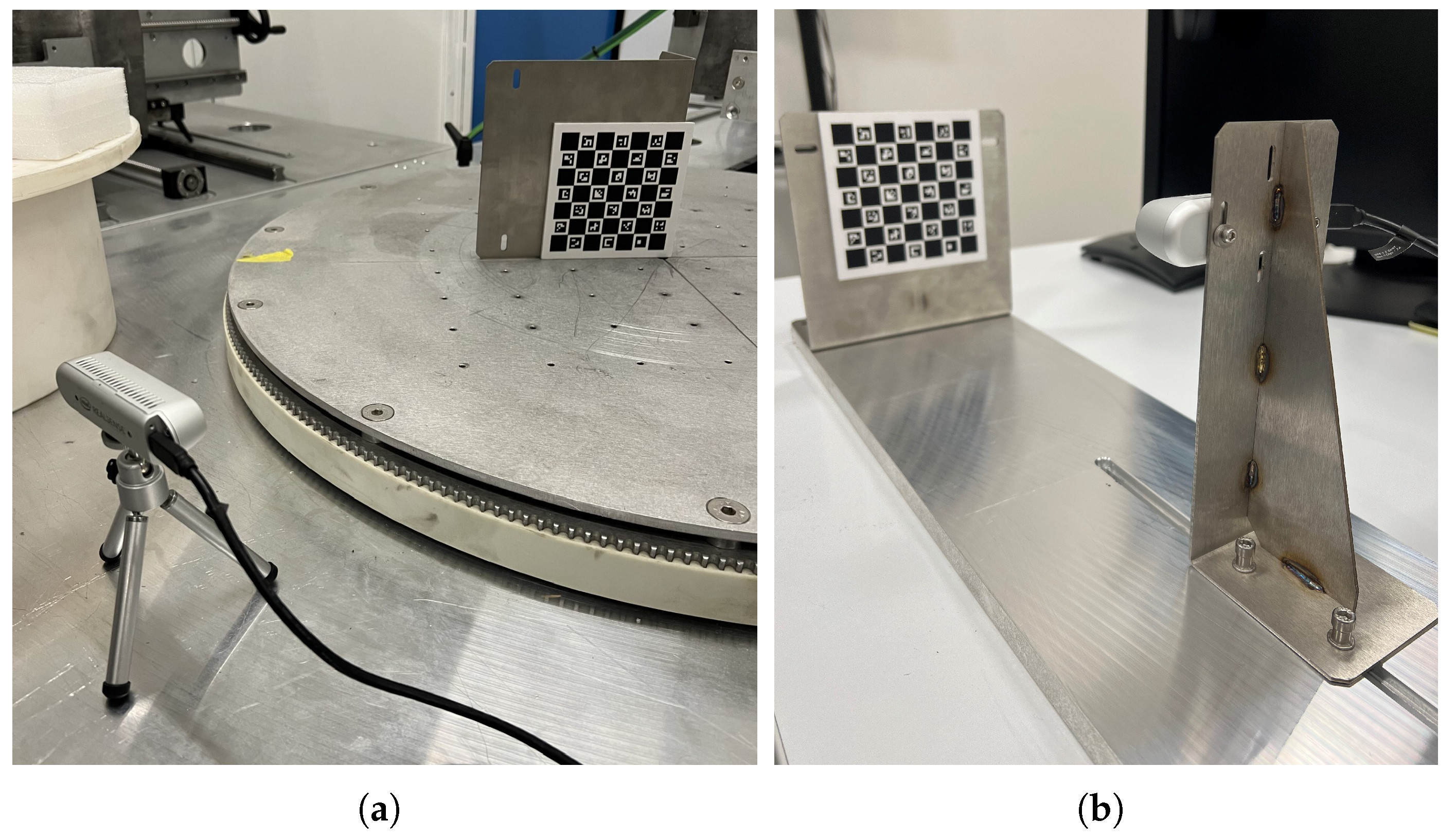
Figure 4.
parameters absolute error (bar height; viewing angle and roll ) with standard deviation (error bars) for each wheel position. (a) Continuous acquisition; (b) Cyclic acquisition.
Figure 4.
parameters absolute error (bar height; viewing angle and roll ) with standard deviation (error bars) for each wheel position. (a) Continuous acquisition; (b) Cyclic acquisition.
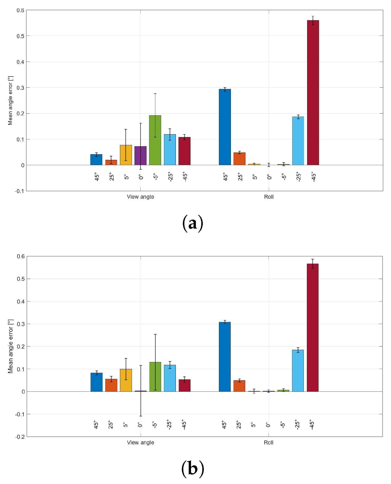
Figure 5.
parameters absolute error (bar height; , , ) with standard deviation (error bars) for each wheel position. (a) Continuous acquisition; (b) Cyclic acquisition.
Figure 5.
parameters absolute error (bar height; , , ) with standard deviation (error bars) for each wheel position. (a) Continuous acquisition; (b) Cyclic acquisition.
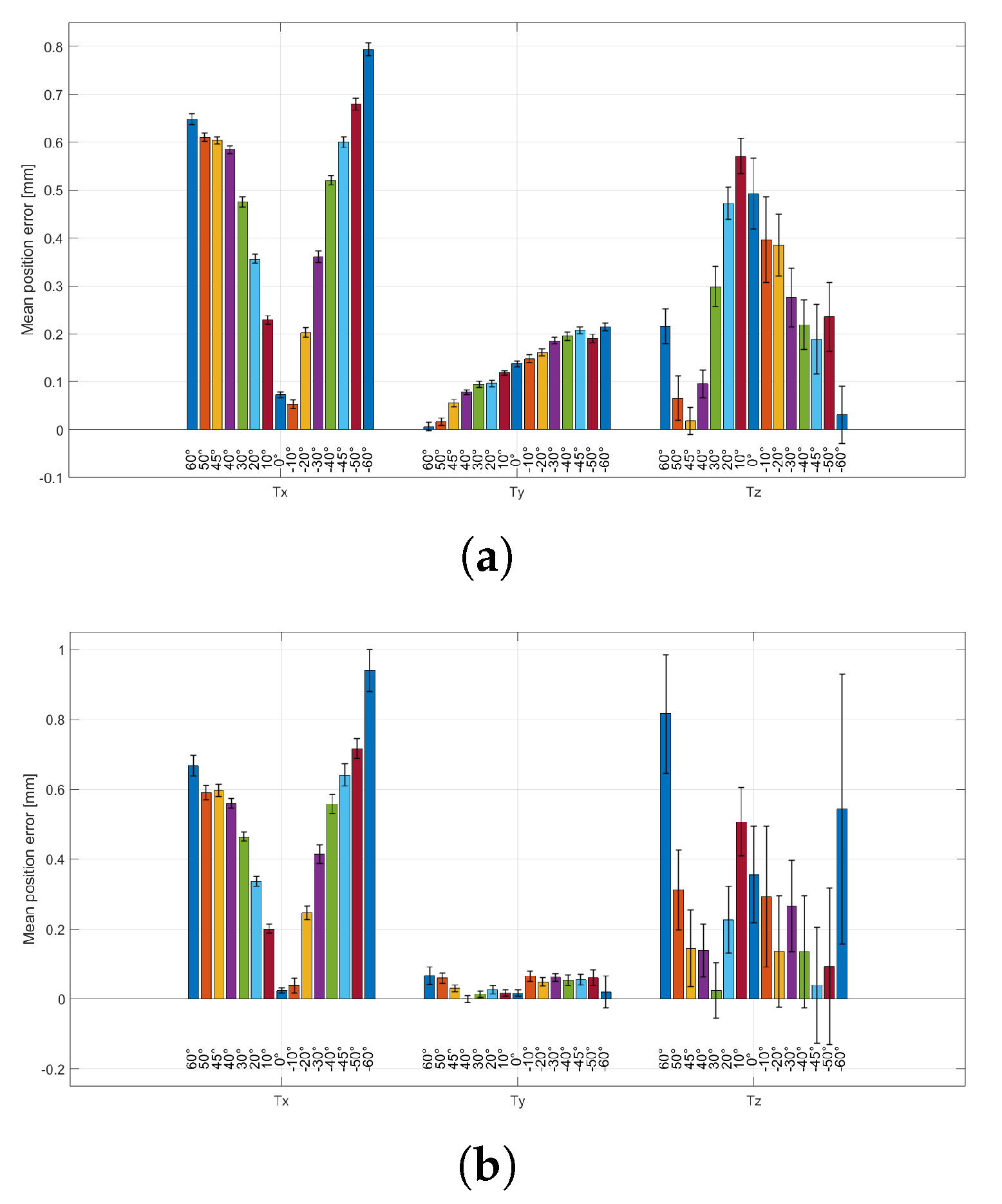
Figure 6.
parameters absolute error (viewing angle and roll ) for each wheel position. (a): parameter fixed at 40 cm; (b): parameter fixed at 60 cm.
Figure 6.
parameters absolute error (viewing angle and roll ) for each wheel position. (a): parameter fixed at 40 cm; (b): parameter fixed at 60 cm.
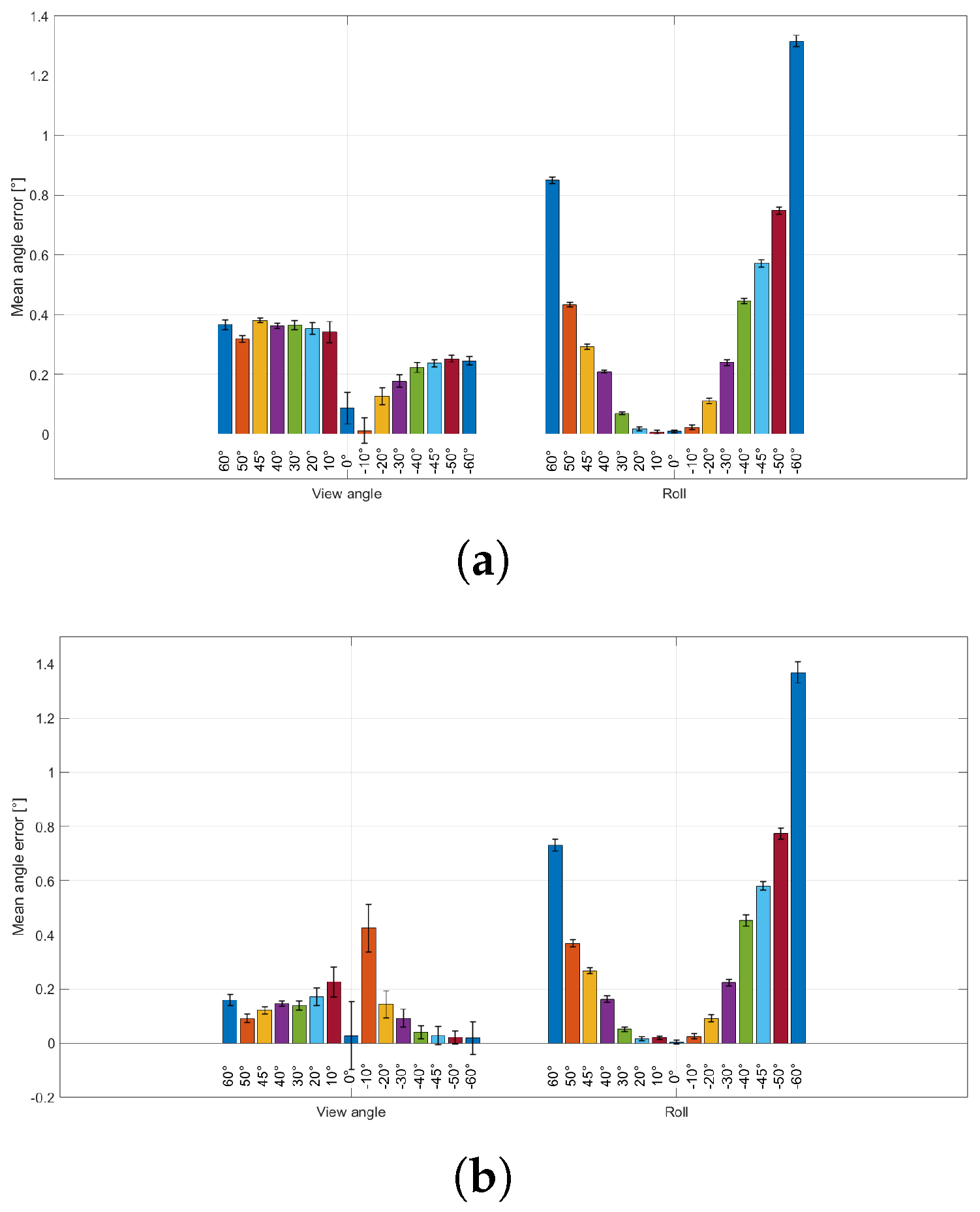
Figure 7.
parameters absolute error (, , ) for each wheel position. (a): parameter fixed at 40 cm; (b): parameter fixed at 60 cm.
Figure 7.
parameters absolute error (, , ) for each wheel position. (a): parameter fixed at 40 cm; (b): parameter fixed at 60 cm.
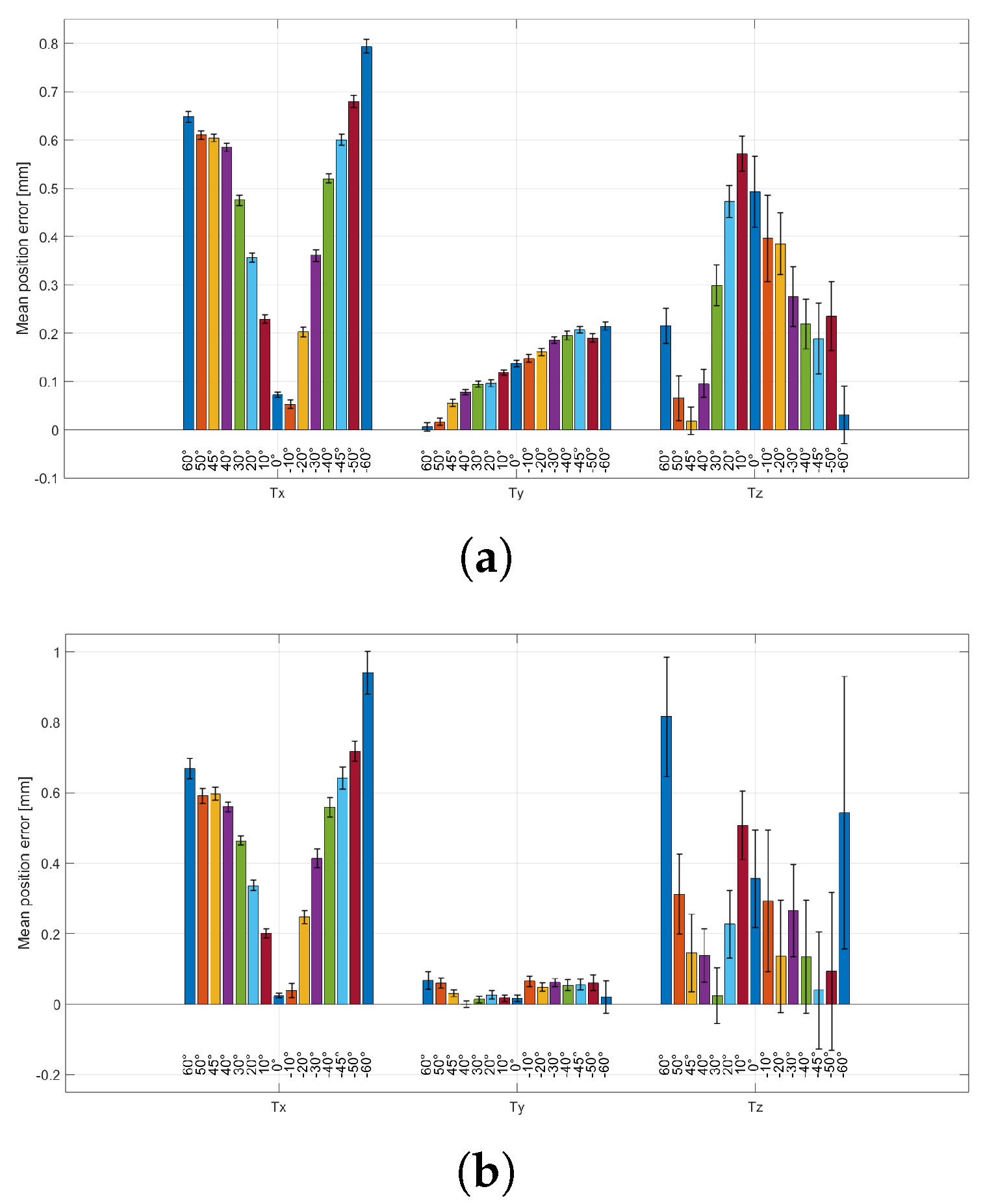
Figure 8.
(a): parameters absolute error (bar height; viewing angle and roll ) with standard deviation (error bars) for each camera-to-ChArUco distance. (b): parameters mean absolute error (bar height; , , ) with standard deviation (error bars) across repeated measurements, for each camera-to-ChArUco working distance.
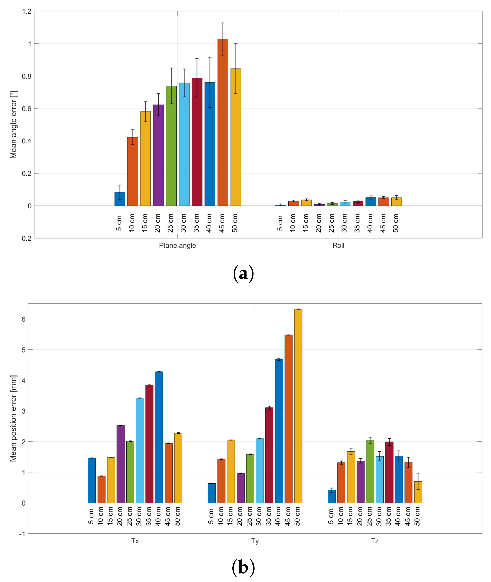

Table 1.
Main characteristics of the RGB module of the Intel D435 3D camera.
| Frame resolution | 1920x1080 |
| Frame rate | 30 fps |
| Sensor technology | Rolling shutter |
| Sensor FOV (H x V) | 69° x 42° |
| Sensor resolution | 2 MP |
Disclaimer/Publisher’s Note: The statements, opinions and data contained in all publications are solely those of the individual author(s) and contributor(s) and not of MDPI and/or the editor(s). MDPI and/or the editor(s) disclaim responsibility for any injury to people or property resulting from any ideas, methods, instructions or products referred to in the content. |
© 2026 by the authors. Licensee MDPI, Basel, Switzerland. This article is an open access article distributed under the terms and conditions of the Creative Commons Attribution (CC BY) license (http://creativecommons.org/licenses/by/4.0/).
Copyright: This open access article is published under a Creative Commons CC BY 4.0 license, which permit the free download, distribution, and reuse, provided that the author and preprint are cited in any reuse.


