
Submitted:
13 January 2026
Posted:
14 January 2026
You are already at the latest version
Abstract
In low-Earth-orbit (LEO) satellite networks, the requirement for intelligent parameter-adjustment strategies has become increasingly critical due to the presence of highly dynamic channel conditions, limited spectrum resources, and complex interference environments. In this paper, a method for optimizing LEO satellite communication links based on deep reinforcement learning (DRL) is proposed. Through the optimization of the transmit power, the modulation and coding scheme (MCS), the beamforming parameters, and the retransmission mechanisms, adaptive link control is achieved in dynamic operational scenarios. A multidimensional state space is constructed, within which the channel state information, the interference environment, and the historical performance metrics are integrated. The spatio-temporal characteristics of the channel are extracted by means of a hybrid neural architecture that incorporates a convolutional neural network (CNN) and a long short-term memory (LSTM) net-work. To effectively accommodate both continuous and discrete action spaces, a hybrid DRL framework that combines proximal policy optimization (PPO) with a deep Q-network (DQN) is employed, thereby enabling cross-layer optimization of the physical-layer and link-layer parameters. The results demonstrate that substantial improvements in throughput, bit error rate (BER), and transmit-power efficiency are achieved under severely time-varying channel conditions, which provides a new idea for resource management and dynamic-environment adaptation in satellite communication systems.
Keywords:
satellite communication links
; deep reinforcement learning
; parameter adjustment strategy
; highly dynamic channel
; link optimization
1. Introduction
With the acceleration of global digital transformation, 5G/6G and the integration of space and sky have become the key technology direction of satellite Internet development. The LEO satellite communication system is receiving increasing attention from countries due to its advantages of low latency, low cost, and high bandwidth [1,2]. Large-scale constellation initiatives, represented by Starlink and OneWeb, are undergoing accelerated deployment worldwide with the objective of providing high-speed broadband services with global coverage [3,4,5]. However, LEO satellite communication links still face a series of substantial technical challenges. The high orbital velocity of LEO satellites leads to rapid temporal variations in channel characteristics, which in turn result in pronounced doppler frequency shifts and reduced channel coherence time [6,7]. In addition, satellite–ground links are influenced by atmospheric effects, with high-frequency bands being particularly susceptible to impairments such as rain attenuation [8,9]. Moreover, the stringent constraints on resources carried by satellites render power, computational capacity, and spectrum exceptionally valuable [10,11]. Traditional control strategies based on fixed thresholds or static rules are inadequate for such highly dynamic environments. And the optimization method of adaptive coding and modulation (ACM) faces bottlenecks such as large parameter space, strong environmental dynamics, and multi-objective conflicts. Therefore, the investigation of new intelligent optimization methodologies for LEO communication links is of significant importance.
There are currently three main methods for optimizing satellite communication links: methods based on fixed rules, techniques based on ACM, and methods based on constraint optimization. Biglieri E adoptd a fixed rule approach and considered three modulation formats, namely 16-PSK, 16-QAM, and a 16 element amplitude phase keying scheme with two amplitude levels [12]. The method of ensuring link connectivity through conservative parameter configuration results in low resource utilization efficiency. Bischl H, et al. have verified that ACM is easy to implement on large-scale networks and can effectively meet the target group error rate requirements even under deep fading conditions [13]. Huang J, et al. proposed an efficient utilisation of the ACM scheme, which shows that, under the premise of the same transmission power, the throughput of two proposed ACM schemes is nearly six times that of a fixed MCS [14]. This ACM technology can dynamically adjust transmission parameters according to channel conditions to adapt to different transmission environments, which has been used on many communication satellites [15,16]. However, in high dynamic environments, this method may experience response lag and may not achieve the expected results in complex situations due to neglecting other parameter coupling. Besides, there is an optimization theory based approach for centralized coordination and signal processing to achieve efficient interference management and flexible network adaptation [17]. Actually, this convex optimization framework generally relies on precise channel models and has a high computational complexity, making it difficult to adapt to highly dynamic environments. Therefore, the common drawback of current methods is the lack of real-time perception and decision-making capabilities for high dynamic environments, which cannot effectively handle the complexity of multi parameter joint optimization.
With the rapid development of artificial intelligence (AI), more and more AI based methods are being applied in the field of communication [18,19]. DRL, with its ability to autonomously learn optimal strategies through interaction with the environment, is precisely capable of addressing high dynamic and complex environmental challenges, providing a new solution for optimizing LEO satellite communication links [20]. Deng B, et al. proposed an innovative resource management framework for the next generation heterogeneous satellite networks, which can achieve cooperation between independent satellite systems and maximizing resource utilization [21]. Huang et al. have investigated the power allocation problem in LEO satellite networks based on DRL technology and further proposed a scheme based on efficient near end PPO, which can learn the optimal power allocation strategy without knowing any prior information to maximize the overall system rate [22]. From the application of different intelligent algorithms, DRL in the field of communication has shown great potential. And the current research results fully demonstrate the effectiveness of DRL in handling communication optimization problems [23,24], especially its ability to learn complex mapping relationships from high-dimensional states, providing a solid technical foundation for this paper. However, the optimization objects and control variables in current DRL based communication optimization methods are still relatively single. Due to the complex and highly dynamic characteristics of the actual LEO communication environment, communication quality often requires joint decision-making of multiple control variables (including discrete and continuous variables).In order to address the challenge of collaborative dynamic optimization of continuous and discrete control variables in LEO satellite communication links, a new method for optimizing LEO satellite communication links based on hybrid DRL is proposed in this paper. On the basis of perception of the link status, this method optimizes multiple control variables such as output power, beamforming parameters, coding and modulation schemes, and retransmission strategy through intelligent the agents to maximize communication quality while ensuring the link reliability.
The contribution of this paper is to have designed a multi-dimensional state space and CNN-LSTM feature extraction network to achieve accurate perception of high dynamic channel environments, and propose a hybrid DRL architecture combining PPO and DQN, effectively solving the problem of collaborative decision-making between continuous and discrete parameters in LEO satellite link optimization. The method in this paper provides a new technological approach for the intelligent optimization of LEO satellite communication systems, which has important theoretical value and practical significance.
2. Dynamic Channel Model for LEO Satellite Communication Link
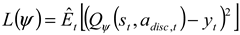
The channel dynamic model of LEO satellite communication link is the basis for simulating high fidelity channel environment and also the guarantee of data authenticity in the DRL algorithm simulation training process. In addition to the traditional free-space path loss, the quality of LEO satellite communication link is also determined by multiple factors such as doppler frequency shift caused by high-speed motion, rain attenuation, absorption loss and tropospheric scintillation caused by the atmosphere, as shown in Figure 1. The key time-varying factors affecting communication link performance are modeled in this section, and an environmental state perception model is provided for DRL by generating a channel state information matrix that contains amplitude, phase, and multipath information.
2.1. Free-Space Path Loss Model
Based on the theory of electromagnetic wave propagation, the energy of electromagnetic waves will gradually disperse on the same phase plane during spatial propagation, which means that as the propagation distance increases, the energy loss of electromagnetic waves becomes more severe. In general, when calculating the propagation loss in free-space, only the direct path is considered. When the transmitting end uses an ideal point source antenna, the signal power will be evenly distributed within a spherical area, and the received signal power can be expressed as follows [25]:
where is the signal transmission power; is the signal reception power; is the antenna gain at the transmitting end; is the antenna gain at the receiving end; is the wavelength and is the propagation distance. When the gain of both the transmitting antenna and the receiving antenna is 1, the free-space loss can be expressed as follows:
2.2. Doppler Frequency Offset Model
The Doppler frequency offset is related to the carrier frequency, the movement speed of satellites and end users, while the Doppler frequency offset change rate describes the speed at which the Doppler frequency shift changes over time, as shown in Figure 2.
In a LEO satellite communication system, the satellite continues to move at high speed, and under the same conditions, the corresponding Doppler frequency offset and Doppler frequency offset change rate are also larger than those in ground systems. The Doppler frequency offset can be expressed as follows [26]:
where is the carrier frequency; is the relative motion velocity between the satellite and the ground, is the angle between the direction of ground terminal movement and the satellite-to-ground link, and is the speed of light. In the scenario of the LEO satellite moving at a high speed, when the satellite accesses the ground station at the minimum access elevation angle, the component of the velocity vector on the straight line of the satellite-to-ground link is at its maximum, corresponding to the largest Doppler frequency shift. Conversely, when the elevation angle between the satellite and the ground station is 90°, the component of the velocity vector on the straight line of the satellite-to-ground link is zero, and the corresponding Doppler frequency shift is also zero. Typically, the Doppler frequency shift of the received signal can reach the order of magnitude of tens to hundreds of KHz.
2.3. Rain Attenuation Model
Due to the scattering and absorption effects of rainfall on electromagnetic waves, when satellite signals pass through rainfall areas, some of the energy will be scattered or absorbed by raindrops. Especially in communication frequency bands above 10 GHz, the impact of rain attenuation on communication quality cannot be ignored [27]. Given the latitude position of the ground station , the corresponding rain layer height can be calculated.
When the satellite enters the rain area, the angle between the inclined path and the ground is , and the length of the inclined path can be expressed as:
where is the altitude of the ground station. And the size of the horizontal projection distance can be expressed as:
Based on the slant path length of satellite signals passing through rain areas, the rain attenuation that results in an average horizontal projection distance exceeding 0.01% of the time over a year can be expressed as:
where is the attenuation rate per-unit time; is the height correction factor.
2.4. Other Loss Models
Gas absorption loss : This loss is mainly caused by oxygen and water vapor, and can be calculated according to the ITU-RP.676-11 model, which is related to frequency and elevation angle. In the 10-30 GHz frequency band, the typical range of this loss is 0.1 to 1dB.
Tropospheric scintillation loss : This loss is mainly caused by the rapid fluctuations in signal amplitude caused by atmospheric turbulence, which can be estimated using the model in ITU-R P.618-10 model.
The channel of LEO satellite communication link can be modeled as a time-varying complex gain. The comprehensive channel gain for a flat-fading channel can be expressed as:
where is the initial random phase offset; is the loss caused by the atmosphere, which satisfies . is the other losses, which can be used for the addition of subsequent dynamic factors. is a random process characterizing small-scale fading, such as Rician fading model:
where is a complex Gaussian random process, and is the Rician factor, which denotes the ratio of the power of the direct path component to the power of the multipath scattering component. The higher the elevation angle, the larger the tends to be.
Construction of CSI matrix: In practical simulation, it is necessary to discretize and sample the channel. The channel state information of the LEO satellite communication system is represented as a complex matrix , where is the number of receiving antennas. is the number of transmitting antennas. is the number of subcarriers. Each element in the matrix follows the aforementioned comprehensive channel model, encompassing various dynamic loss information. In this paper, for the convenience of DRL training simulation, the matrix size is set to , and the complex matrix is subjected to dimensionality reduction. The mean statistical characteristics are used to represent the channel state, and the modulus of each complex is normalized to obtain a CSI matrix . This high-dimensional, time-varying CSI matrix constitutes the core environmental state for DRL intelligent agent training.
3. Performance Index Model of Communication Link
The performance index model of LEO satellite communication system is the basic reference for constructing reward function in DRL algorithm. A weighted comprehensive reward function is designed for training optimization of DRL in this section, which contains multiple key performance indicators such as throughput, bit error rate, transmission delay, and power consumption. This function serves as a learning guide for the DRL agent, enabling it to not only pursue high speed but also take into account communication reliability, real-time performance, and energy efficiency when exploring strategies, ultimately achieving optimality of the overall system performance.
3.1. Normalized Throughput
Throughput is a core metric for measuring the efficiency of data transmission in a communication system. The effective throughput rather than the theoretical peak of the physical layer is used as a measure, which can be expressed as:
where is the channel bandwidth, measured in Hz. is the modulation order (e.g., M=4 for QPSK and M=16 for 16QAM). BLER is the block error rate, which refers to the probability of a data block (such as a codeword) being received incorrectly. It is related to the bit error rate (BER), but better reflects the actual transmission failure after forward error correction (FEC) encoding. is the maximum theoretical throughput of the system, used for normalization.
3.2. Bit Error Rate (BER)
The BER is the fundamental indicator for measuring communication reliability, which can be calculated theoretically or statistically calculated using Monte Carlo methods. The calculation of theoretical BER depends on different MCS. For QPSK modulation and M-QAM modulation (M ≥ 16), the BER can be expressed as follows:
where is the bit-to-noise ratio, which is the ultimate manifestation of link budget and is related to the received power, noise power, etc. and refer to the complementary error function and Gaussian Q function, respectively.
3.3. Transmission Delay
Transmission delay is crucial for evaluating the quality of communication , especially for applications demanding high real-time performance. The total transmission delay can be expressed as follows:
where is the propagation delay, determined by the satellite-to-ground distance. , where is the instantaneous satellite-to-ground distance and is the speed of light. is the transmission delay, which is related to the packet and symbol rate , . is the processing delay, including the time for encoding, modulation, demodulation, decoding, etc., which can be modeled as a fixed value or a random distribution. is the queuing delay, which occurs when multiple data streams compete for the same output port in on-board routers, and is related to traffic load and scheduling algorithms. It can be estimated using M/M/1 or more complex queuing theory models.
3.4. Power Efficiency
The power efficiency is directly related to the energy sustainability and lifespan of satellites. The power consumption of the communication subsystem can be simply expressed as:
where is the transmission power, with the unit of W. This is a key variable that the DRL agent can directly optimize. is the efficiency of the power amplifier. The efficiency of typical amplifiers ranges from 30% to 60%, that is, ; is the actual power consumption of the power amplifier. is the static power consumption, which includes the power required for the normal operation of baseband devices such as modems and digital signal processors.
Fusing the aforementioned multiple indicators into a scalar reward value is the key to guiding the behavior of DRL agent. The multi-objective optimization problem is transformed into a single-objective problem using the linear weighted sum method. The immediate reward obtained at time step can be simply expressed as:
 where is the normalized throughput metric, i.e., ; is the processed BER indicator, i.e., , whose purpose is to amplify the influence of BER, ensuring it holds a reasonable weight in the reward function; is the normalized latency metric, i.e., , where is the maximum latency tolerable by the system; is the normalized power consumption metric, i.e., , where is the maximum allowable transmit power; andare the weight coefficients. These coefficients determine the agent's preference for different performance metrics. These coefficients determine the agent's preference for different performance metrics. In pursuit of high throughput and high reliability of the system, while imposing certain constraints on latency and power consumption, the coefficients can be expressed as:
4. Optimization Algorithm of LEO Satellite Communication Link Based on DRL
On the basis of the reward function design in the section 3, a hybrid DRL architecture combining PPO and DQN is proposed in this section, as shown in Figure 3. By collecting multidimensional state information from the communication environment, the original state space is established, and a hybrid structure combining CNN and LSTM is used to extract spatiotemporal channel features. The extracted feature vector is simultaneously transmitted to both PPO and DQN branches. And the PPO branch has the advantage of handling continuous action spaces and is responsible for finely adjusting transmission power and beamforming weights; The DQN branch has the advantage of handling discrete decisions and is responsible for selecting modulation and coding schemes as well as retransmission time. The optimization of the communication link is achieved through iterative training of the DRL agent, which solves the problem of traditional methods being difficult to collaboratively optimize continuous and discrete parameters, and can improve the performance of communication system.
4.1. Design of State Space
In the optimization algorithm for LEO satellite communication link based on DRL, the design of the state space is crucial as it determines the agent's level of understanding of the environment and decision quality. Besides the CSI matrix , the complete state space also includes multidimensional state variables, which can be expressed as:
where is the number of packets in the current queue. reflects the system load status, avoids buffer overflow, and guides traffic control strategies, which satisfies . is maximum capacity of queue (number of packets). is the delay statistics information, which satisfies . and are the average delay and delay standard deviation, respectively. is the current transmission power and its utilization rate relative to the maximum power, which satisfies . is the current transmission power. is the maximum allowable transmission power. is the position and attitude angle, which satisfies . is a part of the device status information, which satisfies . is the amplifier temperature. is the DC power consumption. is the historical sequence of BER, representing the sequence of BER measurement values in the past period of time, which can be expressed as:
where is the historical window length (typical value: 10-100 sampling points). The sampling interval is generally 1ms-100ms. Similarly, the other three historical data states can be expressed as:
4.2. Design of Mixed Action Space
The action of the DRL agent is defined as a composite action comprising both continuous and discrete components: .For the continuous action space , it is used for fine-tuning radio frequency parameters, which can be expressed as:
where is the adjustment amount of transmit power. It is a normalized continuous value, typically ranging from [−1,1]. The actual transmit power is obtained through linear mapping, which can be expressed as:
where is beamforming weight (phase offset); is the maximum allowable transmit power; is the minimum allowable transmit power; and is the number of array elements in a phased array antenna. For the discrete action space , it is used to make category selection decisions, which can be expressed as:
where MCS Index is a discrete value that can be set to establish the correspondence between the index and the MCS, such as 0-QPSK with a coding rate of 1/2, 1-16QAM with a coding rate of 3/4, and 2-64QAM with a coding rate of 5/6. Each index corresponds to a predefined combination of modulation order and coding rate. Retry Count is the maximum number of retransmissions. In protocols based on automatic repeat request (ARQ), the agent can choose the maximum number of retransmissions for link layer packets, such as 0 (no retransmission), 1, 2. This allows the agent to strike a balance between latency and reliability.
4.3. Design of Hybrid DRL Algorithm
The original state (including CSI matrix, historical BER, etc.) passes through a shared feature extraction network, which employs a CNN-LSTM hybrid structure. The CNN part is used to extract local features of state information with spatial structure, such as the CSI matrix. The LSTM part is used to capture long-term dependencies in time series, such as historical BER and queue status. And partial scalar states are feature extracted by fully connected networks. The final extracted feature vector is simultaneously transmitted to both PPO and DQN branches, as shown in Figure 3.
The PPO branch comprises an Actor network and a Critic network. Actor network : The input is the feature vector ; the output is the mean and variance of continuous action . It defines the probability distribution of taking continuous actions under state . The goal is to learn the optimal continuous control strategy.
Critic network : The input is feature vector ; the output is state value , representing the expected cumulative reward that can be obtained starting from state in the future. The goal is to evaluate the quality of the current state, which is used to guide the update of the Actor network.
The PPO algorithm ensures the stability of policy updates through its tailored objective function, which can be expressed as:
 where is the probability ratio between the old and new strategies. is the advantage function estimation, indicating the superiority or inferiority of a certain action relative to the average level. It is usually calculated by the Critic network and actual rewards. When , is a hyperparameter; is the immediate reward obtained at time , and is the state value output by the Critic network.
The DQN branch includes a Q-network , designed to handle discrete decision-making problems. The input is a feature vector ; the output is a Q-value vector, where each element corresponds to the Q-value (expected long-term cumulative reward) of a discrete action combination . The final action decision is to choose the discrete action with the maximum Q-value through either greedy or ε-greedy strategies, which can be expressed as:
where is a randomly selected discrete action, and is the action with the highest Q-value under the current state . DQN updates the network through temporal difference error, with the goal of minimizing the following loss function:
 where is the target Q-value; is the discount factor, where ; is the target Q-network, whose parameter is periodically copied from the main network to stabilize training. is the predicted Q-value, while is the target Q-value; is the set of all weights and biases in the DQN. is the immediate reward obtained at time ; is the highest Q-value among all possible actions in the next state .
The final collaborative training and decision-making process is as follows:
a. Forward propagation: At each time step, the feature extraction network extracts features from the original state to obtain a feature vector .
b. Action generation: The PPO-Actor network samples a continuous action based on the current policy. And the DQN-Q network selects the discrete action with the highest Q-value.
c. Environmental interaction: Perform composite action , and obtain reward and the next state from the environment (LEO satellite communication link simulator).
d. Experience storage: Store the transferred sample into the experience replay buffer.
e. Network Update: Sample a batch of data from the buffer. Update DQN branch: Calculate Q-value loss and perform backpropagation. Update PPO branch: Use the sampled data to calculate the advantage function , then update the Actor network by maximizing the clipped objective function , and update the Critic network by minimizing the value function error.
5. Results and Discussion
The optimization algorithm designed in this paper requires a large number of randomly constructed channel scenarios to be used for offline training of DRL. The trained model can be deployed online and dynamically output the optimal link configuration parameters based on real-time channel state information. The random DRL training scenarios are designed in this section and simulation results are obtained through examples. The simulation results of the algorithm are compared with that of the traditional method, which proves the effectiveness and progressiveness of the new method.
5.1. Design of Random Training Environment
To ensure that the trained DRL agent possesses strong generalization capabilities, a highly randomized dynamic channel simulation environment was constructed. The core parameters and the range of randomization for the environment are shown in Table 1.
The environmental joint simulation architecture adopts a simulation platform that deeply integrates STK and NS-3, which can be expressed as:
where is the entire joint simulation platform; is the STK simulation environment, responsible for generating satellite orbits, positions, and geometric relationships between the satellite and ground links; is the NS-3 network simulator, responsible for simulating network protocols, packet transmission, and business flows; is the interface module between STK and NS-3, which enables real-time data exchange between the two platforms. The data stream from STK to NS-3 can be expressed as:
where and represent the coordinate position vectors of the satellite and the gateway station in three-dimensional space, respectively; The loss of dynamic channels refers to the dynamic channel model in Section 2. The business model parameters are as follows: VoIP service: packet size of 120 bytes, arrival interval of 20ms; video stream: bitrate of 2Mbps, packet size of 1500 bytes; FTP service: file size 10MB.
5.2. Training Process and Hyperparameters of DRL
The training of DRL is conducted on high-performance servers and the training hyperparameters are shown in Table 2.
The DRL training process is as follows:
a. Initialization: Randomly initialize the DRL network parameters of the satellite.
b. Scene loop: Simulate a complete process of the satellite passing through a ground station (approximately 10-15 minutes of simulation time) for each training episode.
c. Step loop: Observe at each time step (such as 10ms): the agent obtains state from the environment; and the agent outputs action through PPO and DQN networks; Feedback the agent outputs action to the environment, while receiving the reward and the new state ; Store experience tuple in the experience replay buffer; Then periodically sample from the buffer and update the network parameters. The simulation convergence result during the training process is shown in Figure 4.
5.3. Simulation Results and Analysis
After completing the training of DRL, the performance evaluation was completed under a fixed test scenario (orbit height 975km, initial elevation 30 °, rainstorm conditions - rainfall rate 25mm/h, two medium power interference sources), and compared with the two existing methods. The two traditional methods for comparison are as follows:
one is a method of the fixed strategy that adopts a conservative fixed configuration, with a transmission power of 40 dBm, MCS of 16QAM 3/4, and a fixed beam, which is the benchmark scheme for many traditional satellites. Another method is ACM, which is a widely studied adaptive method that dynamically adjusts the MCS based on the instantaneous SNR feedback from the receiving end through a preset SNR-MCS mapping table, but with a fixed transmission power. The performance comparison results are shown in Table 3.
It can be seen from Table 3 that compared with the fixed strategy, the new method dynamically adjusts parameters through the DRL algorithm and maintains low BER and high throughput by adjusting MCS and intelligent power control in harsh channels. However, the implementation complexity and computational cost of the fixed strategy are relatively small, while the new method requires a certain amount of computing resources to run the DRL model. Compared with the method of ACM, since ACM only adjusts MCS, while the new method jointly optimizes power and MCS, in the testing scenario, the DRL agent not only reduce MCS but also synchronously adjust the power when the channel is poor. Meanwhile, ACM is a passive response based on the current instantaneous SNR, while the DRL agent can perceive that interference is about to increase through learning and adopt robust configurations in advance to avoid sudden spikes in BER. Besides, the new method also optimizes parameters such as beamforming, further improving signal quality and anti-interference capability. However, the ACM algorithm is simple, easy to understand and deploy, while the DRL model decision logic in this paper is not as intuitive as the lookup table method, requiring more complex training and verification processes.
In summary, the simulation results fully validate the effectiveness of the new method for optimizing LEO satellite communication links based on DRL proposed in this paper. Compared with two typical existing technologies, the new method can achieve improvements in throughput, reliability, delay and energy efficiency in high dynamic and non-stationary LEO satellite channels through the joint decision-making of intelligent cross layer parameters, which demonstrates the strong environmental adaptability and overall performance advantages, and provide a new approach for the next generation of intelligent satellite communication systems.
6. Conclusions
In this paper, a new method for optimizing LEO satellite communication links based on DRL is proposed. The method extracted spatiotemporal features of multidimensional state space through a CNN-LSTM hybrid network and established a hybrid architecture that combined PPO and DQN, enabling the DRL agent to achieve real-time link state perception and jointly decide on discrete and continuous actions such as output power, beamforming, MCS, and retransmission strategies, while ensuring link reliability and maximizing system performance. The simulation results have showed that the new method is effective and progressiveness. And compared with the traditional methods, the new method has three main advantages: firstly, it avoids dependence on precise channel models through DRL; At the same time, it achieves multi parameter collaborative optimization instead of isolated adjustment; Finally, it has the ability to adapt to unknown environments, significantly improving the robustness of the system in dynamic scenarios. The method demonstrates the enormous potential of DRL in the field of satellite communication, providing a new idea for promoting the development of LEO satellite communication towards autonomy and intelligence.
Author Contributions
Conceptualization, Yu.H. and Wang.L.; methodology, Yu.H. and Wu.J.; software, Yu.H. and Li.S.; validation, Yu.H., formal analysis, Yu.H. and Sun.Y.; investigation, Yu.H.; resources, Yu.H.; data curation, Yu.H. and Wu.J; writing—original draft preparation, Yu.H.; writing—review and editing, Yu.H.; visualization, Yu.H. and Sun.Y.; supervision, Yu.H.; project administration, Yu.H.; funding acquisition, Sun.Y. All authors have read and agreed to the published version of the manuscript.
Data Availability Statement
The authors declare data cannot be made public due to privacy concerns.
Acknowledgments
The authors have reviewed and edited the output and take full responsibility for the content of this publication.
Conflicts of Interest
The authors declare no conflicts of interest.
References
- Hui, M.; Zhai, S.; Wang, D.; Hui, T.; Wang, W.; Du, P.; Gong, F. A review of leo satellite communication payloads for integrated communication, navigation, and remote sensing: Opportunities, challenges, future directions. IEEE Internet. Things. 2025, 12, 18954-18992. [CrossRef]
- Zhou, D., Sheng, M., Li, J., Han, Z. Aerospace integrated networks innovation for empowering 6G: A survey and future challenges. IEEE Commun. Surv. Tut. 2023, 25, 975-1019. [CrossRef]
- Kozhaya, S., Kassas, Z. M. A first look at the OneWeb LEO constellation: beacons, beams, and positioning. IEEE T. Aero. Elec. Sys. 2024, 60, 7528-7534. [CrossRef]
- Boley, A. C., Byers, M. Satellite mega-constellations create risks in Low Earth Orbit, the atmosphere and on Earth. Sci. Rep-UK. 2021, 11, 10642. [CrossRef]
- Osoro, O. B., Oughton, E. J. A techno-economic framework for satellite networks applied to low earth orbit constellations: Assessing Starlink, OneWeb and Kuiper. IEEE Access 2021, 9, 141611-141625. [CrossRef]
- Fernandes, M. A., Loureiro, P. A., Fernandes, G. M., Monteiro, P. P., Guiomar, F. P. Digitally mitigating Doppler shift in high-capacity coherent FSO LEO-to-earth links. J. Lightwave. Technol. 2023, 41, 3993-4001. [CrossRef]
- Shi, J., Li, Z., Hu, J., Tie, Z., Li, S., Liang, W., Ding, Z. OTFS enabled LEO satellite communications: A promising solution to severe doppler effects. IEEE Network 2023, 38, 203-209. [CrossRef]
- Behera, B., Raghu, N., Yadav, A., Setia, N., Goyal, D. Satellite-to-Ground Propagation Modelling for High-Frequency Communication Systems. Int. J. Antenn. Propag. 2025, 7, 49-55.
- Sabuj, S. R., Alam, M. S., Haider, M., Hossain, M. A., Pathan, A. S. K. Low Altitude Satellite Constellation for Futuristic Aerial-Ground Communications. CMES-Comp. Model. Eng. 2023, 136. [CrossRef]
- Al-Hraishawi, H., Chougrani, H., Kisseleff, S., Lagunas, E., Chatzinotas, S. A survey on nongeostationary satellite systems: The communication perspective. IEEE Commun. Surv. Tut. 2022, 25, 101-132. [CrossRef]
- Wang, S., Li, Q. Satellite computing: Vision and challenges. IEEE Internet. Things. 2023, 10, 22514-22529. [CrossRef]
- Biglieri E. High-level modulation and coding for nonlinear satellite channels. IEEE T. Commun. 2003, 32, 616-626. [CrossRef]
- Bischl, H., Brandt, H., De Cola, T., De Gaudenzi, R., Eberlein, E., Girault, N., Alberty, E., Lipp, S., Rinaldo, R., Rislow, B., Arthur Skard, J., Tousch, J., Ulbricht, G. Adaptive coding and modulation for satellite broadband networks: From theory to practice. Int. J. Satell. Comm. N. 2010, 28, 59-111. [CrossRef]
- Huang, J., Su, Y., Liu, W., Wang, F. Adaptive modulation and coding techniques for global navigation satellite system inter-satellite communication based on the channel condition. Iet. Commun. 2016, 10, 2091-2095. [CrossRef]
- Neinavaie, M., Kassas, Z. M. Cognitive sensing and navigation with unknown OFDM signals with application to terrestrial 5G and Starlink LEO satellites. IEEE J. Sel. Area. Comm. 2023, 42, 146-160. [CrossRef]
- Martínez P, F. O., Uribe G, G. A., Mosquera P, F. L. OneWeb: web content adaptation platform based on W3C Mobile Web Initiative guidelines. Ing. Invest. 2011, 31, 117-126.
- Shi, Y., Zhang, J., Letaief, K. B., Bai, B., Chen, W. Large-scale convex optimization for ultra-dense cloud-RAN. IEEE Wirel. Commun. 2015, 22, 84-91. [CrossRef]
- Zeng, L., Zhang, C., Qin, P., Zhou, Y., Cai, Y. One Method for Predicting Satellite Communication Terminal Service Demands Based on Artificial Intelligence Algorithms. Appl. Sci-Basel. 2024, 14, 6019. [CrossRef]
- Zhao, B., Liu, J., Wei, Z., You, I. A deep reinforcement learning based approach for energy-efficient channel allocation in satellite Internet of Things. IEEE Access, 2020, 8, 62197-62206. [CrossRef]
- Bhattacharyya, A., Nambiar, S. M., Ojha, R., Gyaneshwar, A., Chadha, U., Srinivasan, K. Machine Learning and Deep Learning powered satellite communications: Enabling technologies, applications, open challenges, and future research directions. Int. J. Satell. Comm. N. 2023, 41, 539-588. [CrossRef]
- Deng, B., Jiang, C., Yao, H., Guo, S., Zhao, S. The next generation heterogeneous satellite communication networks: Integration of resource management and deep reinforcement learning. IEEE Wirel. Commun. 2019, 27, 105-111. [CrossRef]
- Huang, J., Yang, Y., Yin, L., He, D., Yan, Q. Deep reinforcement learning-based power allocation for rate-splitting multiple access in 6G LEO satellite communication system. IEEE Wirel. Commun. Le. 2022, 11, 2185-2189. [CrossRef]
- Ferreira, P. V. R., Paffenroth, R., Wyglinski, A. M. Multiobjective reinforcement learning for cognitive satellite communications using deep neural network ensembles. IEEE J. Sel. Area. Comm. 2018, 36, 1030-1041. [CrossRef]
- Huang, J., Yang, Y., Lee, J., He, D., Li, Y. Deep reinforcement learning-based resource allocation for RSMA in LEO satellite-terrestrial networks. IEEE T. Commun. 2023, 72, 1341-1354. [CrossRef]
- Foschini, G. J., Chizhik, D., Gans, M. J., Papadias, C., Valenzuela, R. A. Analysis and performance of some basic space-time architectures. IEEE J. Sel. Area. Comm. 2003, 21, 303-320. [CrossRef]
- Wang C., Ellis J D. Dynamic Doppler frequency shift errors: measurement, characterization, and compensation. IEEE T. Instrum. Meas. 2015, 64, 1994-2004.
- Giannetti, F., Reggiannini, R. Opportunistic rain rate estimation from measurements of satellite downlink attenuation: A survey. Sensors, 2021, 21, 5872. [CrossRef]
Figure 1.
The channel dynamic model of LEO satellite communication link.
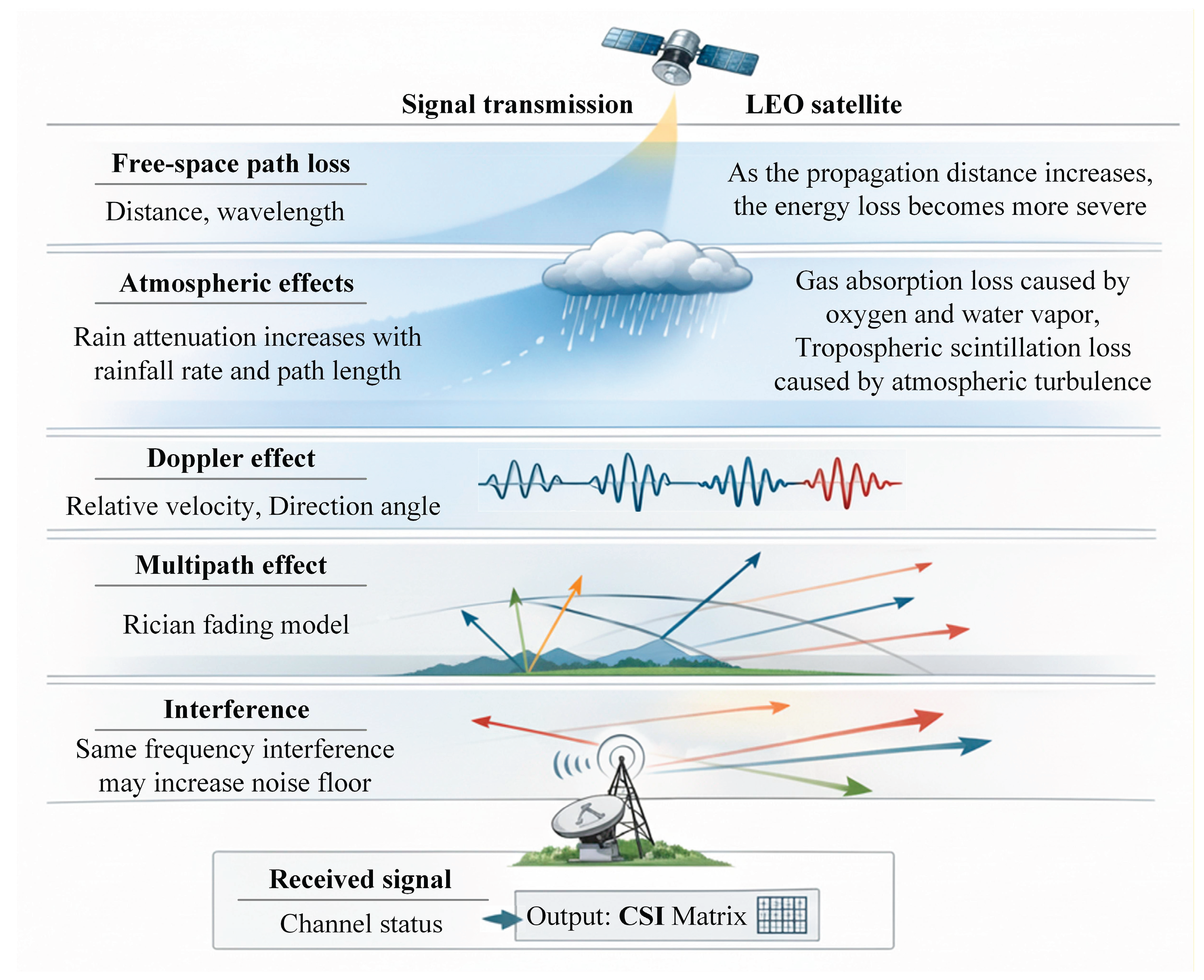
Figure 2.
Doppler frequency shift between the LEO satellite and user equipment (UE).
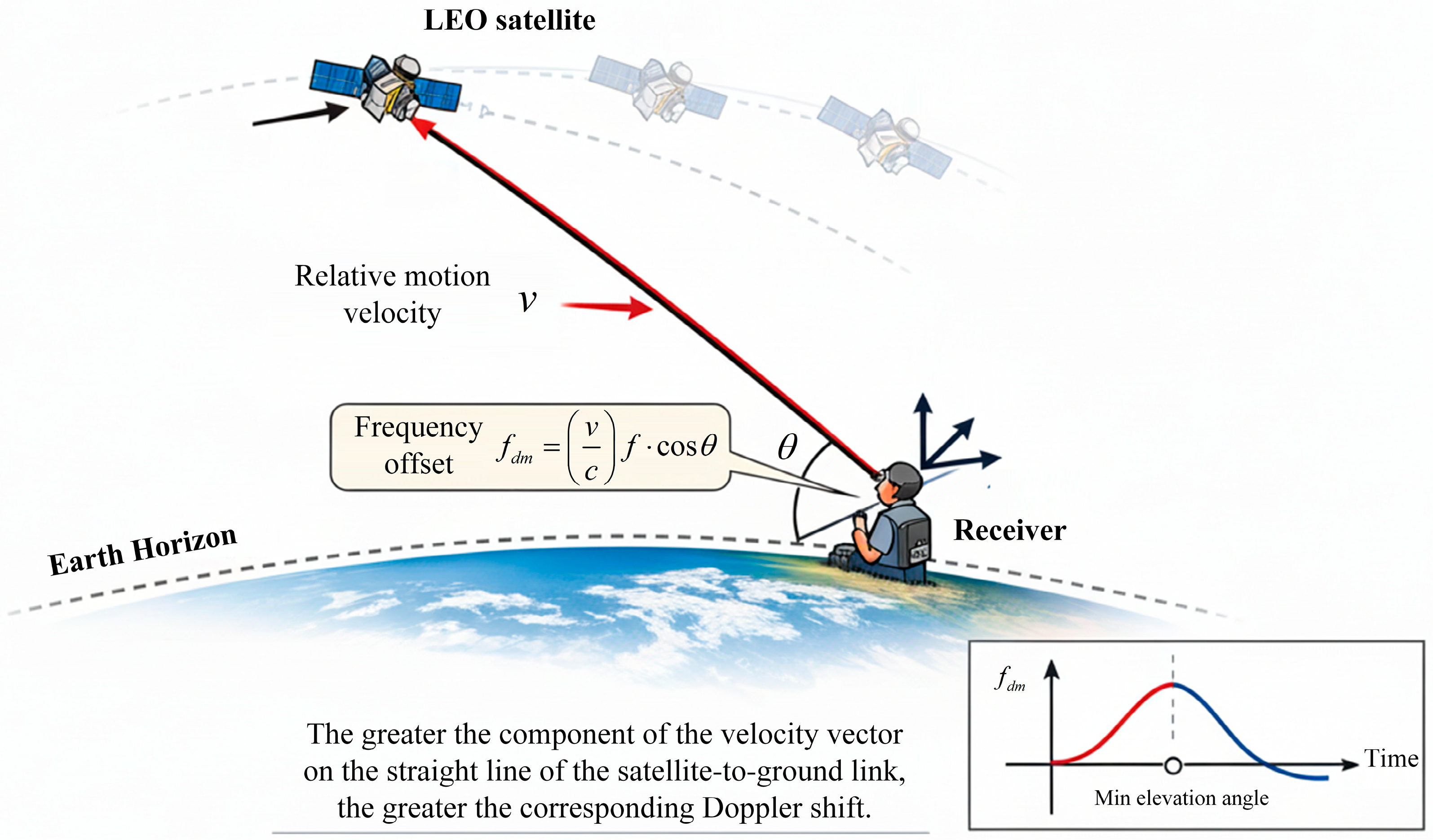
Figure 3.
Optimization algorithm of LEO satellite communication link based on DRL.
Figure 4.
The simulation convergence result during the training process of DRL.
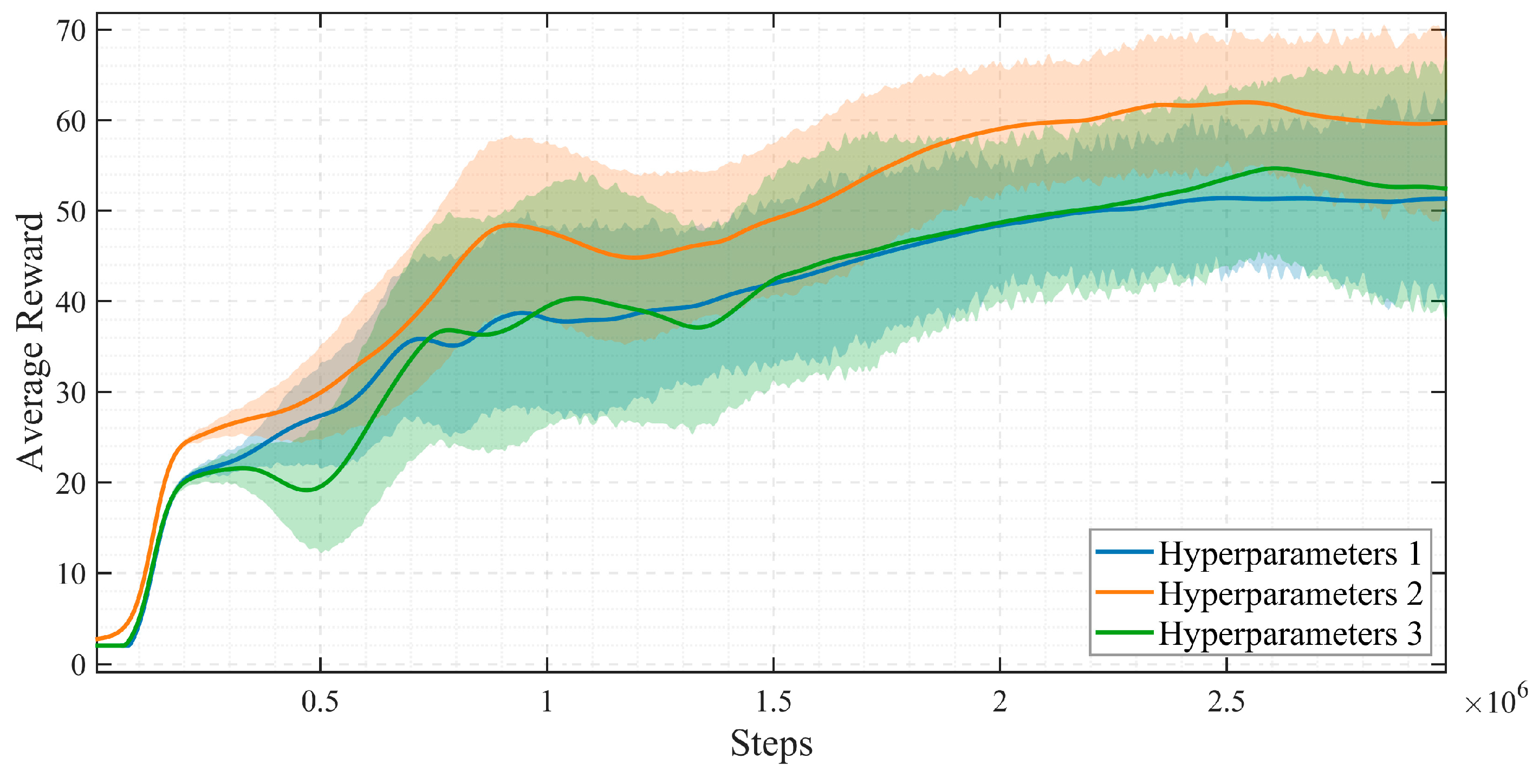

Table 1.
The core parameters and the range of randomization for the environment.
| Parameter | Value range/distribution |
| initial elevation angle | 10°~80° |
| orbital altitude | 950~1000km |
| rainfall rate | 0~50mm/h (exponential distribution) |
| number of interference sources | 0~4(Poisson distribution) |
| interference source power | -20~0 dBm (uniform distribution) |
| Rician factor | 5~15 dB (uniform distribution) |
| Packet arrival rate | 0.1~1.0 Mbps (uniform distribution) |
Table 2.
The training hyperparameters of DRL.
| Hyperparameter | Value |
| PPO learning rate | 3×10⁻⁴ |
| DQN learning rate | 1×10⁻³ |
| discount factor | 0.99 |
| Experience replay buffer size | 1×10⁶ |
Table 3.
The performance comparison results of three methods in a testing scenario.
| Performance metrics | Fixed strategy | ACM | New method (DRL) |
| Average throughput (Mbps) | 58.2 | 67.5 | 74.8 |
| Average BER | 8.5×10⁻⁵ | 2.1×10⁻⁵ | 5.2×10⁻⁶ |
| Average delay (ms) | 22.3 | 18.9 | 16.1 |
| Average power (dBm) | 40.0 (fixed) | 40.0 (fixed) | 29.7 |
Disclaimer/Publisher’s Note: The statements, opinions and data contained in all publications are solely those of the individual author(s) and contributor(s) and not of MDPI and/or the editor(s). MDPI and/or the editor(s) disclaim responsibility for any injury to people or property resulting from any ideas, methods, instructions or products referred to in the content. |
© 2026 by the authors. Licensee MDPI, Basel, Switzerland. This article is an open access article distributed under the terms and conditions of the Creative Commons Attribution (CC BY) license (http://creativecommons.org/licenses/by/4.0/).
Copyright: This open access article is published under a Creative Commons CC BY 4.0 license, which permit the free download, distribution, and reuse, provided that the author and preprint are cited in any reuse.


