
Submitted:
06 January 2026
Posted:
08 January 2026
You are already at the latest version
Abstract
Terahertz waves are located in the "transition zone" between millimeter waves and infrared light. Terahertz video synthetic aperture radar utilizes the high operating frequency, strong radar cross-section intensity, and high azimuth repetition frequency of terahertz waves to detect and track ground moving targets. The conventional methods for detecting moving targets do not take into account the imaging characteristics of moving targets in terahertz video synthetic aperture radar. The Constant False Alarm Rate (CFAR) detection method is used together with other methods to detect moving targets, resulting in unsatisfactory detection performance. This article proposes a new detection method for single channel slow-moving targets in terahertz video SAR based on shadows and light spots, which extracts the features of the shadow and spot areas of the moving target, and determines the position and direction of the moving target through the identification of the shadow and spot areas. The progressiveness of this method is verified by simulation and experimental tests.
Keywords:
image amplitude inversion
; incoherent subtraction
; moving target detection
; shadows
; terahertz video SAR
1. Introduction
Synthetic Aperture Radar (SAR) is a microwave imaging system that operates over long distances, in all weather conditions, and around the clock. Synthetic aperture radar can overcome the limitations of clouds, fog, rain, snow, and darkness, and achieve high-resolution imaging and recognition of targets [1,2]. In order to have the ability to detect, recognize, and track ground maneuvering targets in real-time under harsh conditions such as clouds, dust, smoke, and fog, the concept of Video Synthetic Aperture Radar (Video SAR) has been proposed abroad. By continuously observing the scene, continuous image frames of the target scene are obtained, and the imaging scenes are dynamically presented in the form of video [3,4]. The image and motion status information of moving targets in the scene can be obtained by continuously monitoring the imaging scene. According to the relationship between the frame rate, imaging resolution, and radar operating frequency of strip video SAR [5], the SAR imaging frame rate is positively correlated with the radar operating frequency. Compared with other radars, the higher the operating frequency of a radar, the shorter the imaging time and the faster the imaging speed. To ensure the smoothness of video images, it is required that the frame rate of the image be no less than 5 frames per second. Considering the imaging scene, it is required that the radar operates in the terahertz frequency band. This is an important reason for using terahertz video SAR [6]. In the terahertz frequency band, radar operates at high frequencies, with short wavelengths, and is sensitive to the Doppler effect of moving targets. A higher azimuthal sampling rate is used in data collection, which makes it easier to leave clear shadows of moving targets in the radar illuminated area. At the same time, moving the image of the moving target outside the radar illuminated area is beneficial for separating the image of the moving target from the imaging area and for detecting and locating the moving target. Terahertz video SAR has become a research hotspot in recent years as a new radar imaging system.
At present, moving target detection can be divided into three types: single channel based moving target detection [7,8,9,10,11,12], multi-channel based moving target detection [13,14], and deep learning network-based moving target detection [15,16,17]. The detection method based on single channel synthetic aperture radar data is divided into range velocity and azimuth velocity detection according to the velocity of the moving target in the imaging plane. Due to the different effects of the two speeds on imaging, they have different detection methods. When a moving target has a range velocity, the Doppler spectrum generated by the radar shining on the moving target will shift. By using Doppler spectral shift and the imbalance caused by the shift, clutter is estimated in complex images and background images are established. The image of the moving target can be revealed by image subtraction. There are several typical detection algorithms, such as nominal spectrum method, energy balance method [18], maximum likelihood method [19], and time-domain method [2,20]. When a moving target has azimuthal velocity, the Doppler spectrum of the moving target will be stretched. During self-focusing processing, changes in Doppler modulation frequency are estimated and image sharpness is improved. These methods are used to detect the azimuthal velocity of moving targets, thereby detecting moving targets. There are several typical algorithms for detecting moving targets in terms of azimuth velocity, such as multi-view correlation method [21], image sharpening method [22], crop averaging method [23], time-frequency analysis method [24], and image gradient method [25]. Based on the differences in data from multiple receiving channels, the target is effectively detected from the background through clutter suppression methods. This is the general principle of multi-channel moving target detection method. According to clutter suppression methods, there are several multi-channel moving target detection methods, such as the Phase Center Biased Antenna (DPCA) method that utilizes the spatiotemporal characteristics of the target, the Space Time Adaptive Processing (STAP) method, the Along the Track Interference (ATI) method that uses interferometric processing, and the Multi Aperture Interference Processing method [26]. The process of the moving target detection method based on deep learning networks is as follows: the identified data is divided into mutually exclusive training and testing sets; During the training phase, feature extraction of moving targets is performed on the identified training set to obtain the model parameters of the deep learning network; During the training phase, hyperparameters are adjusted to estimate the accuracy of the training model, and the optimal model is selected for detecting moving targets [27,28,29]. In terahertz video SAR, the process of multi-channel moving target detection is complex and clutter cannot be completely suppressed. The deep learning-based moving target detection method has the problems of insufficient radar data, incomplete and atypical data sets. These issues result in a lack of generalization ability in the trained deep learning network. Meanwhile, the training process is time-consuming and difficult to use for detecting moving targets in terahertz video SAR with high real-time requirements.
In single channel moving target detection methods, the influence of range velocity on moving target imaging is more sensitive than that of azimuth velocity. The electromagnetic waves emitted by terahertz video SAR illuminate the surface of a moving target, causing a certain Doppler frequency shift due to the target’s motion, resulting in the resulting image deviating from its position. The image appears defocused and deformed, forming light spots. At the location of the moving target, due to obstruction from the target, there is a dark area that becomes a shadow. Shadows are important features that distinguish them from the background and represent the position of the target. Shadows are often used as an important basis for detecting moving targets. The detection method of moving targets based on shadows can be considered a reliable and feasible detection method. The detection process of traditional shadow detection methods is as follows: after image denoising, the consecutive frames in the image sequence are registered, and the dynamic shadow information of the moving target is extracted through the inter frame difference of the images. The moving target is detected through CFAR. Reference [30] uses a single frame image to reconstruct the background image and proposes a local feature analysis method based on a single frame image for detecting moving target shadows, which can effectively remove “ghosting” in multi frame image moving target detection algorithms. References [31,32] proposed a shadow detection method based on background subtraction. This method uses “SIFT+RANSAC” algorithm to register multiple frames of images; This method uses median filtering to linearly enhance the region of interest while maintaining resolution; Afterwards, the background image was extracted using the multi frame mean method. The image to be detected is subjected to threshold segmentation and differential with the background image, and the obtained image is subjected to morphological processing and connected domain filtering. The moving target result is obtained through Constant False Alarm Rate (CFAR) detection. The obtained results indicate that the shadow detection method based on background subtraction can effectively extract the shadows of moving targets in video SAR images.
Using existing single channel-based moving target detection methods, residual noise from static backgrounds still exists in the differentiated images, which seriously affects the detection of moving targets. In the terahertz frequency band, the scene of the generated image is small, and the number of moving targets in the illuminated area is small, the image formed by the moving target is separated from the actual shadow position of the moving target, and high requirements are placed on the timeliness of detection. Based on these reasons, this paper proposes a new single channel slow moving target detection method for terahertz video SAR based on shadows and light spots. This method can extract the image and shadow of the moving target through image processing, and obtain the motion direction of the moving target through the features of the image and shadow.
Compared with existing single channel moving target detection methods, the innovation of this paper mainly lies in the following aspects.
1. Perform range compression and azimuth keystone transformation on single channel terahertz video SAR data, and shift the Doppler zero point to the Doppler center, and divide the echo data into left and right sub apertures in the azimuth time domain. Then, image the left and right sub aperture data separately, and perform registration, Gaussian smoothing, amplitude inversion, binarization, and image subtraction on the imaged image. After image subtraction, perform image opening and closing operations and cluster division on the resulting image, and finally obtain a composite image. This series of operations can eliminate background noise and obtain shadows and images of moving targets.
2. The direction of motion of the moving target can be determined based on the vertical position relationship of the markings made in the defined area of the shadow and light spots of the moving target.
3. Based on the image characteristics of the shadow and spots of the moving target, the center position of the shadow and spot of the moving target can be determined for subsequent parameter estimation.
4. After dividing the echo data into left and right sub apertures, there is a problem of inconsistent amplitude changes caused by radar irradiation in the left and right sub apertures. After processing in this article, the influence of radar irradiation on image subtraction has been eliminated.
5. The method proposed in this article for processing single channel terahertz video SAR data is not complicated and employs conventional morphological processing. Fast detection can meet the timeliness requirements of terahertz video SAR moving target detection.
The organizational structure of the remaining part of this article is as follows. Part 2 introduces the reasons and conditions for shadow formation, as well as the differences between moving target shadows and other shadows; Part 3 introduces the theoretical basis and process of moving target detection; Part 4 introduces the simulation and measurement results and their analysis; Part 5 is the summary and outlook of this article.
2. Shadow of Moving Target
The electromagnetic waves emitted by radar illuminate the surface of a moving target, and due to the Doppler effect, the received Doppler spectrum of the moving target undergoes frequency shift, deviating from the actual position of the moving target. Due to the occlusion of the moving target, shadows are left at the true position of the moving target. In low-frequency SAR images, there are shadows generated by moving targets. Due to the presence of a large amount of coherent speckle noise in radar images, the scattered energy of moving targets is low, and shadows are often submerged in the background and noise, making it difficult to identify and detect [33,34]. Terahertz video SAR has a high operating frequency, short wavelength, and is sensitive to the Doppler effect generated by moving targets. Terahertz video SAR is irradiated on the surface of a moving target, resulting in a significant frequency shift and deviation from the radar’s irradiation area. At the true position of the moving target, there is a noticeable dark area compared to the surrounding area, and shadows become an important feature of moving target detection.
2.1. Formation of Shadows Generated by Moving Targets
Figure 1 shows the imaging scene of the moving target and the intensity distribution of the shadow. Terahertz video SAR flies along the X-axis, and the moving target moves along the Y-axis perpendicular to the radar’s flight direction. At an imaging accumulation time, the actual position of the moving target forms a dark area, which is the shadow of the moving target. The intensity of the shadow is related to the duration of the obstruction at that location. The position in the middle is obscured for a long time, resulting in a dark shadow. The dark color at both ends is slightly light. The higher the speed of the moving target, the shorter the duration of the obstructed area, and the less noticeable the shadow formed at its location. The light spot on the left side of the moving target is the image of the moving target. Due to the geometric shape of the moving target, the spatial variability in the azimuth direction leads to geometric deformation of the moving target. During the detection process, the shape similarity between the target and the real target is poor. In terahertz video SAR images, shadows and images of moving targets can be observed.
Weak reflection areas in imaging scenes can form shadows under radar illumination, while stationary targets at high altitudes can form shadows. Figure 2 is a schematic diagram of the shadow formed by a stationary target under radar illumination. Figure 2a is a schematic diagram of the shadow formed by the reflection of no energy in the unlit area observed from the radar line of sight angle. Figure 2b is a schematic diagram of the shadow formed by the elevation target during the radar accumulation time. The middle position is the imaging area of the stationary target. Shadow areas are formed on both sides of the imaging area due to the obstruction of elevation targets. During the imaging accumulation time, the near end of the stationary target is constantly obstructed, forming a deep shadow area. The shadows of stationary targets at high altitudes are caused by the obstruction of the area during radar imaging, resulting in lower energy than the surrounding areas. The mechanism of shadow formation for moving targets is essentially the same as that for weak reflection areas and stationary targets at high altitudes. This poses difficulties for detecting shadows of moving targets.
2.2. Shadow Intensity of Moving Targets
The radar cross section is represented as the equivalent area, which is converted from the power ratio of the scattering field to the incident field. The power ratio reflects the backscattering ability of the target towards the incident electromagnetic energy, and its expression is as follows.
Among them, is the target distance, is the scattering field strength, and is the incident electromagnetic field strength. When is far enough, the incident wave illuminating the target is approximated as a plane wave. The radar shines on the surface of a moving target on the ground, and the moving target is equivalent to a metal plate. The radar cross section (RCS) of a finite sized metal rectangular plate illuminated at an angle of to the normal direction is expressed as [35,36]:
Among them, is the free space wavenumber, is the wavelength, and are the length and width of the metal plate. Convert equation (2) into the expression for the radar operating frequency :
Using physical optics method, the RCS of a metal plate is proportional to the square of the illuminated radar frequency. A metal plate with a width of 2m and a length of 1.5m was irradiated with 5.3G (C-band), 10G (X-band), 30G (Ka band), and 220G (THz band) radars, respectively. The radar cross sections (RCS) at observation angles of 0 for different bands are shown in the Figure 3.

Table 1.
Peak radar cross sections of metal plates at different frequency bands.
| parameter | C-band (5.3G) | X-band (10G) | Ka band (30G) | THz band (220G) |
|---|---|---|---|---|
| RCS (dBsm) | 45.4776 | 50.9921 | 60.5345 | 77.8406 |
| Equivalent square(km) | 0.2 | 0.4 | 1.1 | 7.8 |
The radar cross section generated by the terahertz frequency band acting on a metal plate is much larger than that generated by other low-frequency radars, and this indicates that terahertz radar has stronger backward reflection capability. The radar shines on the surface of the moving target, and the reflected electromagnetic energy generated by terahertz radar is the strongest. Due to the Doppler effect, the image formed by a moving target deviates from its actual position in the form of a light spot. At the actual position of the moving target, the most electromagnetic energy is carried away, leaving the most obvious shadow. Strong background scattering is more conducive to the formation of more prominent shadows. This is one of the reasons why terahertz video SAR can use shadow detection methods.
3. Single Channel Moving Target Detection
Compared to multi-channel moving target detection, using single channel data from terahertz video SAR for moving target detection is simpler and faster, which is exactly what video SAR requires.
3.1. Shadow Intensity of Moving Targets
The echo signal generated by radar shining on the surface of a moving target is different from the echo signal shining on a stationary target. The moving parameters of the moving target affect the imaging position and the shape of the target. According to the model established by Raney, the geometric relationship between the moving target and the carrier in the oblique plane is shown in Figure 4.
In the Figure 4, OA is the flight direction of the carrier, with a speed of , and the position of the carrier platform at time is A. M is the location of the moving target, with a range velocity , a range acceleration ,an azimuth velocity , and an azimuth acceleration .The shortest distance from the moving target to the flight path is ,and the instantaneous slant distance from the moving target to the carrier radar at time is .
The impact of azimuthal acceleration on the imaging of moving targets is small, ignoring the third or more terms of . The above equation is expressed as:
Among them, . The equivalent azimuthal velocity of the carrier is related to the azimuthal velocity, range acceleration, and slant distance from the flight platform to the moving target.
Generally, the velocity in the range direction is small. In equation (5), due to the reason of , the influence of on imaging is ignored. After orthogonally demodulating the echo signal of the moving target, the obtained signal is:
Among them, is the signal amplitude and is the radar wavelength. Compared with stationary targets, the echo signal of moving targets has an additional linear term of azimuth time with a center frequency . The frequency modulation rate of linear frequency modulation signals is also different from that of stationary targets. The frequency modulation rate of moving targets is related to the flight speed of the carrier, the azimuth velocity of the moving target, the range acceleration, and the shortest distance from the target to the carrier. The range velocity causes displacement of the range unit, and the displacement of the range unit results in bending of the range unit data storage; The range velocity causes the lateral displacement of the target in the image, with a displacement of .The azimuth velocity and range acceleration cause secondary phase errors, which cause defocusing of moving targets in azimuth. In the terahertz frequency band, the offset of the center frequency is inversely proportional to the radar wavelength, that is, at equal velocities in the range direction, the offset generated by terahertz video SAR is greater than that of other low-frequency radars, which is beneficial for detecting moving targets.
3.2. Theoretical Basis of Moving Target Detection
The operating frequency of terahertz video SAR is high, and data is generally collected in dechirp mode. the difference frequency output signal of the radar is:
Among them, , is the amplitude of the echo from the scattering point, is the azimuth time, is the range time, is the radar center frequency, is the modulation frequency, is the range pulse width, is the distance from the point target to the radar, is the reference distance, and is the speed of light, .
The Fourier transform is applied to the range direction of equation (7), and the expression in the difference frequency domain after dechirp is:
Among them, is the difference frequency. Without considering the constant term, the shortest distance from a stationary target S to the flight path in the imaging scene is , and the instantaneous slant distance from the stationary target to the radar at time is .
The echo signal of point target S is:
Perform azimuth Fourier transform to obtain:
Among them, the azimuth frequency is .
Without considering the constant term, the echo signal of point target M is:
The equation obtained by performing an azimuthal Fourier transform on the above equation is:
Among them, , .
In the squint mode, it can be seen from equation (11) that the Doppler spectrum of the stationary target S is symmetrical about the Doppler zero point; From equation (13), it can be seen that there is a frequency shift in the Doppler spectrum of the moving target M that is related to its motion state. The Doppler spectrum of a moving target is asymmetric about the Doppler zero point. Static clutter is similar to stationary targets, and the clutter spectrum is symmetric about the Doppler zero point. In the azimuth time domain, the radar signal is divided into two sub apertures with the Doppler center zero as the boundary, imaged separately, and then non coherent subtraction of the images can preserve moving targets, suppress clutter and noise, improve the signal-to-noise ratio of the signal, and enhance the detection capability of moving targets.
Divide the azimuth time-domain signal into left and right sub aperture signals with time zero as the boundary, where the sub aperture smaller than 0 is the left sub aperture and the sub aperture larger than 0 is the right sub aperture, and perform Fourier transform on them respectively.
For stationary targets, the result of the left sub aperture is:
The result of the right sub aperture is:
Observing the results in the azimuth frequency domain, there is a linear phase difference between the left and right sub apertures, but the amplitude images are the same. For the moving target, the processing result of the left sub aperture is:
The processing result of the right sub aperture is:
Like stationary targets, there is a linear phase difference in the imaging results of the left and right sub apertures of the moving target M, but the amplitude images are the same. In theory, by dividing data into left and right sub apertures in the azimuth time domain and imaging them, the resulting targets can be cancelled. However, for moving targets, a range direction movement is added to the moving target, which results in the motion information of the moving target remaining during image subtraction.
3.3. Image Domain Processing
The azimuth time-domain signal is subjected to Fourier transform to obtain left and right sub aperture images. The amplitude changes of the same pixel in the left and right sub aperture images are different. The difference in amplitude variation can be understood as the asymmetry of the left and right channels. The amplitude inconsistency of the left and right sub aperture pixels is affected by the offset of radar illumination. Due to the influence of the external environment, the images formed by the left and right sub apertures have azimuthal offsets. In order to cancel out static clutter and noise, it is necessary to align the images of the left and right sub apertures. This article adopts the SAR-SIFT image registration method based on feature points to achieve registration of left and right sub apertures. The amplitude of complex images is affected by random noise and coherent speckle. After image registration, Gaussian smoothing is applied to the left and right sub aperture images to eliminate the influence of coherent speckle noise. Shadows exist in the radar illuminated area. Due to the influence of speckle noise, shadow energy is low, which is not conducive to shadow extraction and detection. This article uses the method of image amplitude inversion to extract shadows in the scene. The specific method is to obtain the energy of each pixel, convert the pixel with the lowest energy to the one with the highest energy; The pixel with the highest energy is converted to the one with the lowest energy. Taking this as an example, the energy of each pixel is converted proportionally. These treatments enable the shadow image to be highlighted in the scene. In order to reduce the influence of clutter and noise, the image with inverted amplitude is binarized. Non coherent subtraction is performed after binary processing on the left and right sub images to obtain a cancelled image. In incoherent subtraction images, in addition to the radar illuminated edges, stationary targets are cancelled out and the image of moving targets is left behind. The image is further decomposed into two images. Images with amplitudes greater than zero are positive images, while images with amplitudes less than zero are negative images. Perform on-off operations on both positive and negative images to reduce the impact of small pixels on detection. In both positive and negative images, imaging points with similar characteristics are grouped together, and the imaging points are clustered and the clustering regions are identified. Compared to the K-Means algorithm, the Density-Based Spatial Clustering of Applications with Noise (DBSCAN) clustering algorithm does not require a predetermined number of clusters and can identify noise/outliers. The DBSCAN clustering algorithm can discover clusters of any shape, and is insensitive to outliers and initial values. This article uses the DBSCAN clustering algorithm to cluster and partition the imaging points of positive and negative images, and identifies the clustering areas. Finally, the positive and negative images are combined into one image. Based on the identification of clustering regions in the synthesized image, the shadow position, image position, and motion direction of the moving target are determined. The entire processing flow is shown in the Figure 5.
3.4. Theoretical Basis of Moving Target Detection
In the subtraction image, in addition to the edges illuminated by the radar, stationary targets in the imaging scene are cancelled out, the shadows of moving targets are highlighted, and the image of moving targets is displayed in the form of light spots. Due to the incoherent subtraction of the left and right sub apertures, the position of the region with opposite amplitudes (black and white areas) is used to determine the moving target. In the same range interval of the subtraction image, there are two regions with opposite amplitudes, which can be judged as the shadow and image of the moving target. The region located in the radar irradiation area is the shadow of the moving target, and the region outside the radar irradiation area is the image of the moving target. In the shadow area and the image area of the same moving target, the areas with opposite amplitudes have opposite positions in terms of their vertical positions. The direction of motion of the moving target is determined based on the vertical position relationship of the amplitude within the shadow area and the image area.
In the composite image, the areas with clustering labels from positive and negative images are delineated. If there are two enclosed areas within the same range unit interval, it is considered that these two enclosed areas are the shadow area and image area of the same moving target. Within the shadow area and the image area, the direction of the moving target is determined based on the vertical position relationship identified by clustering from positive and negative images. The specific approach needs to be considered based on the actual situation. In the destructive image, when performing incoherent subtraction between the left and right sub aperture images, subtracting the right sub aperture image from the left sub aperture image is exactly opposite to subtracting the left sub aperture image from the right sub aperture image. The vertical position relationship of different amplitude regions in the shaded area is exactly opposite. Similarly, the determination of the motion direction of moving targets within the area of the light spot should take into account the specific situation of incoherent subtraction.
In many cases, if the shadow area is not obvious or the two types of markings in the shadow area cannot be detected, the light spot outside the radar illumination area is used to detect moving targets. The image of the moving target shifts outside the imaging area and is easily detected.
In this case, areas with different amplitudes or areas with two different markings outside the radar illumination area are considered as images of moving targets. Similarly, the direction of motion of the moving target is determined based on the vertical position relationship between the two markers within the area of the light spots.
4. Verification of Simulation and Measurement
The simulation and actual measurement data of terahertz video SAR are from a test experiment, and the main parameters are shown in Table 2.
4.1. Simulation
Considering that the target has a certain geometric size, 9point targets are used to represent the stationary target and the moving target, respectively. The motion parameters of the 9point targets for the moving target are the same, as shown in Figure 6a. Set the range direction speed to 10 m/s and image the radar illuminated area. The imaging result is shown in Figure 6b.
The stationary targets of 9 points are set at the center of the imaging scene, and the moving targets of 9 points are set at the edges of the center of the imaging scene, as shown in Figure 6a. The simulation results of moving and stationary targets are shown in Figure 6b. The image of a stationary target is at the center of the imaging scene, while the image of a moving target deviates from its original position and is located on the left side of the scene. Figure 6c and Figure 6d show the local images of the left and right sub aperture imaging of the moving target, respectively. In Figure 6e, the image formed by the moving target is preserved, and black and white areas representing different amplitudes are exposed. These black and white areas are used as features of the light spot of the moving target for detection. The vertical position relationship between black and white areas representing different amplitudes is used to determine the direction of motion of moving targets. When performing incoherent subtraction, the left sub aperture data is subtracted from the right sub aperture data. In the subtraction image, within the spot area, the white area is above and the black area is below, indicating that the direction of motion of the moving target is upward, that is, radially away from the radar.
Considering the applicability of this method, moving targets in the C-band imaging scene were selected for simulation. The imaging parameters are as follows:
Table 3.
Main parameters of C-band SAR imaging scenarios.
| Parameters | value | unit | Parameters | value | unit |
|---|---|---|---|---|---|
| operating frequency | 5.3 | GHz | slant range | 20 | km |
| Imaging mode | strip | - | Equivalent radar speed | 150 | m/s |
| Pulse duration of emission | 25 | µs | Range modulation frequency | 2.5e11 | Hz/s |
| Range sampling rate | 7.5 | MHz | Azimuth sampling rate | 104 | Hz |
Nine-point targets representing moving and stationary targets with certain geometric dimensions were used for simulation, and the positions of stationary and moving targets are shown in Figure 7a. The range direction motion speed of the moving target is 5m/s, and the imaging results are shown in Figure 7b. The image formed by a stationary target is located at the center of the scene, while the image formed by a moving target deviates from its actual position. The imaging result of the moving target after image subtraction is shown in Figure 7c. Like the imaging scene in the terahertz frequency band, the spot area of the moving target in the C-band has a black and white region that is amplitude dependent, and the black and white region is in a vertical position relationship.
The moving targets in the C-band and terahertz band exhibit similar technical characteristics using the algorithm proposed in this paper. The simulation results show that this method is also applicable to the detection of low-frequency moving targets.
4.2. Actual Testing Verification
The measured data in this article comes from a terahertz video SAR flight test conducted in a certain location in 2021. The main parameters of the test scenario are shown in Table 2. The operating frequency of terahertz frequency band video SAR is high, and the data in the range direction is sampled using a dechirp mode with a range bandwidth of 900MHz and a sampling frequency of 400MHz. Terahertz video SAR uses a dechirp mode to sample range data, and there is a problem of range drift in the echo signal. Therefore, the echo signal is subjected to range compression and range migration correction before sub aperture partitioning. This article uses Keystone transform to correct range walk in range migration correction. In the range frequency domain, azimuth time domain, the Doppler zero point is shifted to the Doppler phase center, and the echo data is divided into left and right sub apertures with the Doppler phase center as the boundary. Image processing was performed on the left and right sub aperture data separately, and the imaging results are shown in Figure 8. In addition to image registration, the amplitude of pixels in the left and right sub aperture images is greatly affected by radar illumination.
Specifically, the area illuminated by the radar is not the same in the left and right sub aperture images. The amplitude changes of pixels in the same area of the image have inconsistency, and simple image subtraction methods are difficult to obtain a clean background of moving targets. Careful examination of the left and right sub aperture images reveals that most of the moving target images deviate from the imaging area in the form of light spots, which facilitates the detection of moving targets. However, there are still images of moving targets that fall into the imaging area and mix with strong scattering points.
Terahertz video SAR uses a dechirp mode to collect range data, and a higher sampling frequency is used in the azimuth direction. The image formed by the moving target deviates from the actual position and enters the area outside the radar illumination area. If there are no artificial targets in the scene, the image of the moving target can be determined by the light spot in the non -illuminated area. If there are artificial targets in the illuminated area, the backward reflection energy of the artificial targets is strong, resulting in “ghosting” in the non-illuminated area, which seriously interferes with the detection of moving targets. The shadow left by the moving target in the illuminated area is due to the obstruction of radar electromagnetic waves by the moving target during the imaging accumulation time, and there is a weak energy zone in the true position of the moving target. The shadows of moving targets, weak reflection areas (such as water pools), and shadows left by elevation targets are essentially weak energy areas. The images formed by weak reflection areas and stationary elevation targets affect the detection of moving targets.
After image registration, Gaussian smoothing, amplitude inversion, and binarization of the left and right sub aperture images, a destructive image is obtained. The image is shown in Figure 9.
The image after subtraction is divided into radar illuminated area and non-illuminated area. White and black target areas with opposite amplitudes are delineated. There is a defined area in both the radar illuminated area and the non-illuminated area parallel to it, which is the moving target. The delineated area in the radar illumination zone is the shadow of the moving target, while the delineated area in the non-illumination zone is the image of the moving target, also known as the light spot. In the shadow and light spot areas of the moving target, there is a vertical position relationship between the white and black target areas within the defined area. Based on the incoherent subtraction situation of image subtraction, the direction of the moving target is determined. Figure 9 shows the result obtained by subtracting the right sub aperture image data from the left sub aperture image data during image subtraction. The white target in the shadow area is above and the black target is below, indicating that the moving target is moving upwards; The white target area in the spot area is below, and the black target area is below, indicating that the moving target is moving upward. On the contrary, if the right sub aperture image data is subtracted from the left sub aperture data during image subtraction, the judgment result is exactly the opposite.
The image after subtraction is divided into positive and negative images, and the DBSCAN clustering algorithm is used to collect similar regions in the image. After performing image opening and closing operations, the positive and negative images are combined to obtain the result shown in Figure 10. Similar to Figure 9, the shadow, light spot, and motion direction of the moving target are determined through the delineation of the image area and the identification within the area.
Overlay the shadows, light spots, and directional markings of the moving target onto the full aperture image to obtain the imaging result of the marked moving target as shown in Figure 11.
The pulse frequency of terahertz video SAR is high, and the radar irradiation area is an elliptical region at the imaging center. There are areas labeled S1, S2, and S3 within the radar illumination area, which represent the shadows of moving targets. There are areas labeled L1, L2, and L3 outside the radar illumination area, which are the images of moving targets. Figure 11 shows that the delineated area labeled L1 and the delineated area labeled S1 are within the same range unit. The delineated area marked as L1 is located at the edge of the radar irradiation area, and it is determined that this delineated area is the light spot of the moving target S1. The delineated area marked as L3 is located in the non-illuminated area of the radar, and the shadow in the image is not obvious. Based on the relationship between the shadow and the light spot, the position of the shadow is estimated to be S3. The strong scattering points in the illuminated area are cancelled out after image subtraction, which does not affect the detection of moving targets.
On a normal road, the motion states of moving targets are diverse. The light spot of the moving target moves outside the radar illumination area, and the shadow left by the moving target in the radar illumination area is not obvious, as shown in Figure 12. By using the method described in this article to process images of complex highway scenes, the detection results are obtained after image subtraction. Outside the radar irradiation area, there are multiple light spot areas with black and white target areas. Based on the black and white areas, these light spot areas are considered as the light spots of moving targets.
The light spots labeled L1-L7 on the left side of the image exhibit typical black and white features, indicating that the moving target is moving from bottom to top. The spot marked as L7-L10 on the right reflects the position of the black and white area of the moving target from top to bottom, and the illuminated area in the middle cannot be detected due to the unclear shadow of the moving target.
In spotlight mode, this method is used to detect moving targets, and the detection results are shown in Figure 13.
The areas marked as L1, L2, and L3 in the Figure 13 are outside the radar irradiation area, while the area marked as S1 is within the radar irradiation area. These areas exhibit black and white characteristics and are represented as moving targets. The light spot distribution of the moving target labeled as L2 is outside the left and right radar illumination areas. The delineated area marked as S2 is at the edge of the radar illumination area, and the technical features of the black and white area are not obvious, but the spot position of the moving target is estimated through the delineated area L2.
The areas marked as L1 and S1, L2 and S2 respectively represent the shadows and light spots of the moving target. Based on the distribution of black and white points in the determined area, the moving target is determined to move upward. The areas marked as L3 and S3 are the shadows and images of moving targets. In the radar illuminated area, the shadows left by the moving targets are not obvious, and images outside the radar illuminated area, namely light spots, are detected during detection. The shadows and images marked as L4 and S4 are moving targets, and in the radar illuminated area, the shadows are not obvious. Outside the radar irradiation area, a long and shallow light spot slides out, and the energy of the light spot is dispersed, and moving target is not detected during detection.
4.3. Discussion
Author names should be styled as follows: first and middle names (given names) or initials followed by surname. Please keep author names consistent from one paper to the next within our publications.
After range compression and range shift correction, the Doppler zero point of a single channel terahertz video SAR is moved to the phase center. Divide the echo data into left and right sub apertures with the phase center as the boundary, and image them separately. After image registration, Gaussian smoothing, amplitude inversion, and binarization processing, the sub aperture images are non-coherently subtracted to obtain a subtracted image. Cluster the subtracted images and perform image opening and closing operations to obtain a composite image. In destructive and synthetic images, based on the image features of the moving target, the shadows and light spots of the moving target, as well as the direction of the moving target, are determined.
This article selected terahertz video SAR scene and C-band SAR scene for simulation to verify the detection algorithm proposed in this article. The simulation results show that there are features of moving targets in the obtained images. During the actual testing process, three scenes were selected for detecting moving targets in strip mode and linear spotlight mode. In subtraction and synthesis images, there are features of moving targets. The simulation and actual measurement results show that the method proposed in this paper can detect shadows, light spots, and motion methods of moving targets, and this method is feasible and effective.
The method proposed in this article may have unsatisfactory detection results. The speed of the range direction of the moving target is too fast, and the image of the moving target passes through multiple azimuth units without energy concentration, resulting in a light spot that fades into the background and is difficult to detect. The moving target is located at the edge of the radar illumination area, and the surrounding noise level is high. The shadow generated by the moving target is not obvious, resulting in poor detection performance. Due to the sensitivity of velocity in the range direction to the imaging of moving targets, the position of the shadow of the moving target can be estimated based on the characteristics of the shadow and light spot generated by the moving target. The vertical position relationship of the black and white areas within the shadow or spot area of the moving target can be used to determine the direction of the moving target, and this method is flexible.
The simulation process using the method proposed in this paper in C-band SAR images can obtain features of moving targets similar to those in terahertz video SAR. In actual detection, the speed of moving targets in the range direction has a significant impact on the imaging of C-band SAR, and the shadows formed at the true position of the radar are not obvious, often being submerged in the imaging background. Moreover, in the C-band, the pulse repetition frequency of the radar is not high, and there is no radar non illuminated area like terahertz video SAR in its imaging scene. The energy in the spot area formed by radar is not concentrated, and the image of the moving target is superimposed on the background, making it difficult to detect the moving target.
5. Conclusions
This article proposes a new detection method for moving targets, and the method proposed in this article is used to detect moving targets in terahertz video SAR. The experiment shows that the method is feasible and effective. In terahertz video SAR, the method proposed in this article can meet the real-time requirements. It is suggested to apply the detection method proposed in this article to practical testing. The method proposed in this paper is effective in detecting moving targets in strip mode and linear spotlight mode. The effectiveness of the method proposed in this paper in circular spotlight mode or moving target detection still needs to be verified. In the circular spotlight mode, it is recommended to use CFAR to detect moving targets in the subtracted image after subtraction.
The detection method has a basis for detection in the moving target detection method proposed in this article, and these bases lie in the features of the moving target in the subtracted image and the synthesized image. Using the features of the moving target mentioned in this article as the features to be extracted by a deep learning network, a deep learning network is constructed to continuously discover subtle features and improve the detection level of moving targets. This is a promising method for detecting moving targets. The detection method proposed in this paper takes advantage of the significant impact of the velocity in the range direction of the moving target on imaging. Further research is needed to investigate the impact of azimuthal velocity on imaging for detecting moving targets.
Author Contributions
Conceptualization, X.L, B.D. and H.W.; methodology, X.L. and S.L; software, X.L. and S.L; validation, X.L. and B.D.; formal analysis, X.L. and S.L; investigation, X.L. and B.D.; resources, Q.F., B.D. and H.W.; data curation, X.L. and B.D.; writing—original draft preparation, X.L.; writing—review and editing, X.L. and B.D.; visualization, X.L. and S.L; supervision, B.D., H.W. and Q.F.; project administration, S.L.,B.D., H.W. and Q.F.; funding acquisition, Q.F. and H.W. All authors have read and agreed to the published version of the manuscript.
Funding
This work was supported by the National Natural Science Foundation of China under
Data Availability Statement
The data are not publicly available due to privacy.
Acknowledgments
We would like to thank the Beijing Institute of Radio Measurement for providing the airborne THz-band SAR data; we are also grateful to the editors and reviewers for their time and effort in reviewing our manuscript and facilitating its publication.
Conflicts of Interest
The authors declare no conflicts of interest.
Abbreviations
The following abbreviations are used in this manuscript: Phase Center Biased Antenna (DPCA) method that utilizes the spatiotemporal characteristics of the target, the Space Time Adaptive Processing (STAP) method, the Along the Track Interference (ATI).
| THz-ViSAR | Terahertz Video Synthetic Aperture Radar |
| SAR | Synthetic Aperture Radar |
| CFAR | Constant False Alarm Rate |
| DPCA | Phase Center Biased Antenna |
| STAP | Space Time Adaptive Processing |
| ATI | Along the Track Interference |
| SIFT | Scale-Invariant Feature Transform |
| RANSAC | Random Sample Consensus |
| RCS | radar cross section |
| DBSCAN | Density-Based Spatial Clustering of Applications with Noise |
References
- B. Huang, Y. Li, X. Han, Y. Cui, W. Li and R. Li.Cloud Removal From Optical Satellite Imagery With SAR Imagery Using Sparse Representation.IEEE Geoscience and Remote Sensing Letters,2015, 12, 1046-1050. [CrossRef]
- H. Sun, M. Shimada and F. Xu.Recent Advances in Synthetic Aperture Radar Remote Sensing—Systems, Data Processing, and Applications.IEEE Geoscience and Remote Sensing Letters, 2017, 14, 2013-2016. [CrossRef]
- E. Bishop, R. Linnehan and A. Doerry.Video-SAR using higher order Taylor terms for differential range. In Proceedings of the 2016 IEEE Radar Conference (RadarConf), Philadelphia, PA, USA, 2016.
- M. R. Khosravi and S. Samadi.Reliable Data Aggregation in Internet of ViSAR Vehicles Using Chained Dual-Phase Adaptive Interpolation and Data Embedding. IEEE Internet of Things Journal, 2020, 7, 2603-2610. [CrossRef]
- S. -H. Kim, R. Fan and F. Dominski.ViSAR: A 235 GHz radar for airborne applications. In Proceedings of the 2018 IEEE Radar Conference (RadarConf18), Oklahoma City, OK, USA, 2018.
- H. B. Wallace.DARPA MMW System Programs and How They Drive Can Compound Semiconductor Technology Needs. In Proceedings of the 2015 IEEE Compound Semiconductor Integrated Circuit Symposium (CSICS), New Orleans, LA, USA, 2015.
- Hartshorn, C.A.; Isaacson, S.D.; Barrowes, B.E.; Perren, L.J.; Lozano, D.; Shubitidze, F. Analysis of the Feasibility of UAS-Based EMI Sensing for Underground Utilities Detection and Mapping. Remote Sens. 2022, 14, 3973. [CrossRef]
- Zhu, Shengqi , et al. Robust moving targets detection and velocity estimation using multi-channel and multi-look SAR images. Signal Processing ,2010,90,2009-2019. [CrossRef]
- Joshi, S.K.; Baumgartner, S.V.; da Silva, A.B.C.; Krieger, G. Range-Doppler Based CFAR Ship Detection with Automatic Training Data Selection. Remote Sens. 2019, 11, 1270. [CrossRef]
- Gao, G. , and G. Shi . The CFAR Detection of Ground Moving Targets Based on a Joint Metric of SAR Interferogram’s Magnitude and Phase. IEEE Transactions on Geoscience & Remote Sensing,2012, 50,3618-3624.
- S. Zhang et al..An Effective Clutter Suppression Approach Based on Null-Space Technique for the Space-Borne Multichannel in Azimuth High-Resolution and Wide-Swath SAR System.IEEE Transactions on Geoscience and Remote Sensing, 2022, 60, 1-28. [CrossRef]
- Jung, Y.-J.; Lee, H.-H.; Shin, H.-C. Enhanced Velocity Extraction of Moving Subject Using Through-Wall-Imaging Radar. Appl. Sci. 2025, 15, 11120. [CrossRef]
- do Nascimento Filho, O.D.; Lorenzzetti, J.A.; Gherardi, D.F.M.; Bezerra, D.X.; Paes, R.L. A Hybrid Strategy Combining Maritime Physical Data to the OpenSARShip RCS Statistics for Fast and Effective Vessel Detection in SAR Imagery. Remote Sens. 2025, 17, 3891. [CrossRef]
- H. Yan et al..A New Method of Robust Ground Moving Target Detection Under Different Backgrounds of Airborne SAR Based on Spatial Deformable Module. IEEE Journal of Selected Topics in Applied Earth Observations and Remote Sensing, 2024, 17, 13000-13015. [CrossRef]
- Zhao, Z.; Wen, Z.; Xue, C.; Cui, Z.; Hou, X.; Zhu, H.; Mu, Y.; Liu, Z.; Xia, Z.; Liu, X. Improved Clutter Suppression and Detection of Moving Target with a Fully Polarimetric Radar. Remote Sens. 2025, 17, 2975. [CrossRef]
- L. Wen, J. Ding and O. Loffeld.Video SAR Moving Target Detection Using Dual Faster R-CNN.IEEE Journal of Selected Topics in Applied Earth Observations and Remote Sensing, 2021, 14, 2984-2994.. [CrossRef]
- Y. Zhang, D. Ding, Z. He and H. Leung.LRSMTD: Low-Rank Plus Sparse Multiple-Term Decomposition of Defocusing Target Detection for Single-Channel Single-Band Single-Pass VideoSAR. IEEE Transactions on Geoscience and Remote Sensing, 2024, 62, 1-14. [CrossRef]
- Y. Jungang, H. Xiaotao, J. Tian, J. Thompson and Z. Zhimin.New Approach for SAR Imaging of Ground Moving Targets Based on a Keystone Transform. IEEE Geoscience and Remote Sensing Letters,2011, 8, 829-833. [CrossRef]
- D. Li, M. Zhan, J. Su, H. Liu, X. Zhang and G. Liao.Performances Analysis of Coherently Integrated CPF for LFM Signal Under Low SNR and Its Application to Ground Moving Target Imaging.IEEE Transactions on Geoscience and Remote Sensing, 2017, 55, 6402-6419. [CrossRef]
- Cumming, Ian G. , and F. H. Wong .Digital Signal Processing of Synthetic Aperture Radar Data: Algorithms and Implementation.2004.
- Miao, Xinying , and Y. Shan . SAR target recognition via sparse representation of multi-view SAR images with correlation analysis. Journal of Electromagnetic Waves and Applications ,2019,33,1-14. [CrossRef]
- Zhu, Shengqi , et al. Ground Moving Target Detection and Velocity Estimation Based on Spatial Multilook Processing for Multichannel Airborne SAR.IEEE Transactions on Aerospace & Electronic Systems,2013, 49,1322-1337.
- L. Shujun, Y. Yunneng, G. Fei and M. Shiyi.Method of moving target detection based on sub-image cancell-ation for single-antenna airborne synthetic aperture radar. Journal of Systems Engineering and Electronics,2007,18, 448-453. [CrossRef]
- Z. Liu, Z. Li, C. Huang, J. Wu and J. Yang.Bistatic Forward-Looking SAR KDCT-FSFT-Based Refocusing Method for Ground Moving Target With Unknown Curve Motion.IEEE Journal of Selected Topics in Applied Earth Observations and Remote Sensing, 2020, 13, 4848-4858. [CrossRef]
- P. Huang, G. Liao, Z. Yang, X. -G. Xia, J. -T. Ma and J. Ma.Long-Time Coherent Integration for Weak Maneuvering Target Detection and High-Order Motion Parameter Estimation Based on Keystone Transform. IEEE Transactions on Signal Processing,2016,64, 4013-4026. [CrossRef]
- J. Wang.Moving-Target Detection in SAR Images Using Difference Between Two Looks. IEEE Journal of Selected Topics in Applied Earth Observations and Remote Sensing, 2019, 12, 4530-4542. [CrossRef]
- J. Ding, L. Wen, C. Zhong and O. Loffeld. Video SAR Moving Target Indication Using Deep Neural Network. IEEE Transactions on Geoscience and Remote Sensing, 2020, 58, 7194-7204. [CrossRef]
- Ren, Shaoqing , et al. Faster R-CNN: Towards Real-Time Object Detection with Region Proposal Networks.IEEE Transactions on Pattern Analysis & Machine Intelligence ,2017,39,1137-1149.
- Y. Li, S. Zhang and W. -Q. Wang. A Lightweight Faster R-CNN for Ship Detection in SAR Images. IEEE Geoscience and Remote Sensing Letters, 2022, 19, 1-5. [CrossRef]
- Z. Liu, D. An and X. Huang.Moving Target Shadow Detection and Global Background Reconstruction for VideoSAR Based on Single-Frame Imagery. IEEE Access,2019, 7,42418-42425. [CrossRef]
- Y. Wang et al.Moving Target Shadow Detection and Velocity Estimation for Video SAR Based on GoDec. In Proceedings of the 2024 IEEE 7th International Conference on Computer and Communication Engineering Technology (CCET), Beijing, China, 2024.
- H. Xu, Z. Yang, M. Tian, Y. Sun and G. Liao.An Extended Moving Target Detection Approach for High-Resolution Multichannel SAR-GMTI Systems Based on Enhanced Shadow-Aided Decision. IEEE Transactions on Geoscience and Remote Sensing, 2018, 56, 715-729. [CrossRef]
- Li, Haixiang , et al. Shadow detection in SAR images based on greyscale distribution, a saliency model, and geometrical matching.International Journal of Remote Sensing,2020,41,1-26. [CrossRef]
- M. Su, P. Ni, H. Pei, X. Kou and G. Xu.Graph Feature Representation for Shadow-Assisted Moving Target Tracking in Video SAR. IEEE Geoscience and Remote Sensing Letters,2025, 22, 1-5. [CrossRef]
- He, Y.; Yang, H.; He, H.; Yin, J.; Yang, J. A Ship Discrimination Method Based on High-Frequency Electromagnetic Theory. Remote Sens. 2022, 14, 3893. [CrossRef]
- Chen, R.; Hua, M.; He, S. Forward Modeling of Robust Scattering Centers from Dynamic Ships on Time-Varying Sea Surfaces for Remote Sensing Target-Recognition Applications. Remote Sens. 2024, 16, 860. [CrossRef]
Figure 1.
Shadows and images of moving targets. (a) Imaging scene of moving targets. (b) Shadow intensity.
Figure 1.
Shadows and images of moving targets. (a) Imaging scene of moving targets. (b) Shadow intensity.
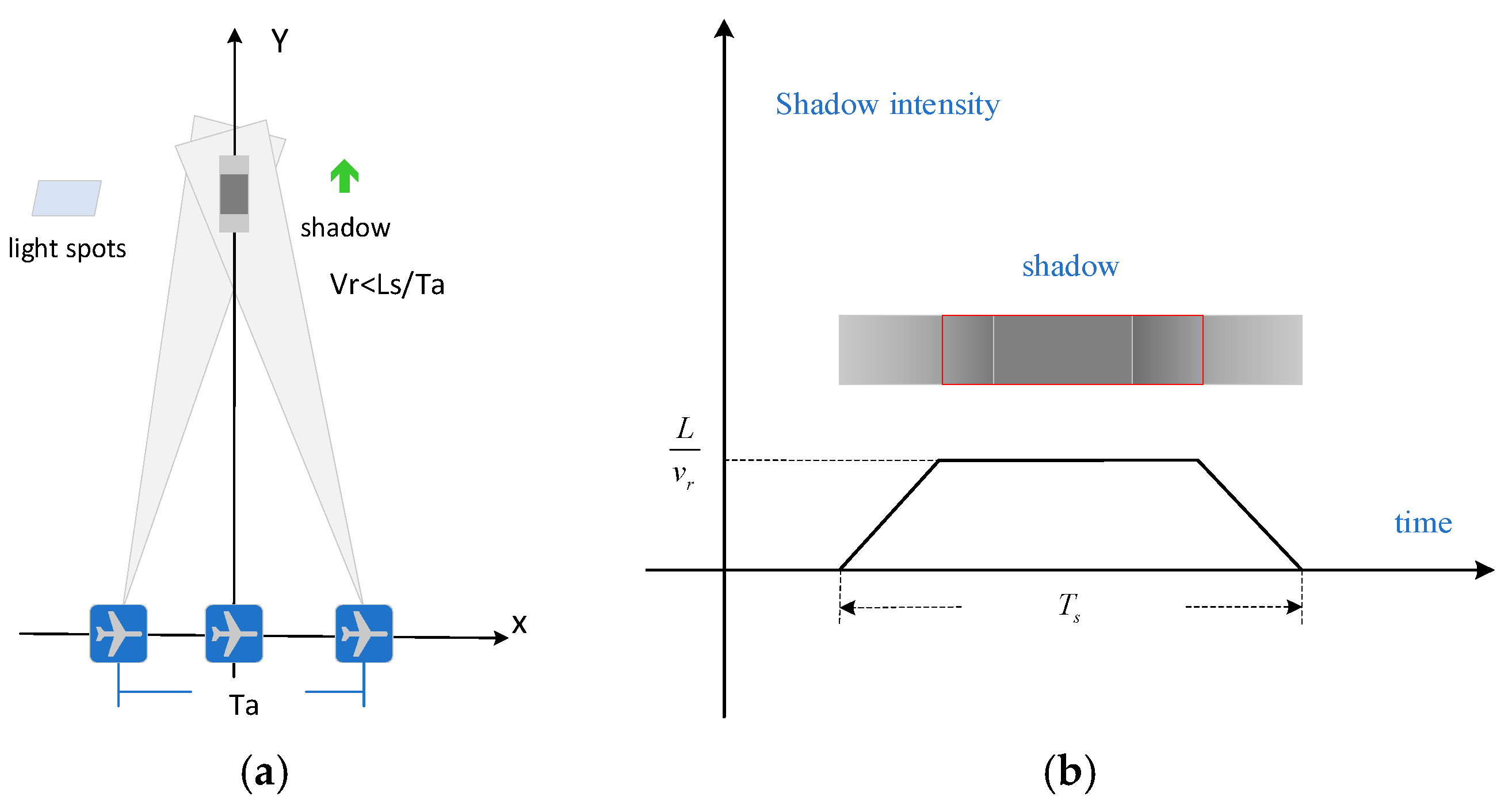
Figure 2.
Shows the shadow generated by the elevation target. (a) Perspective from the range direction. (b) Perspective from the azimuth direction.
Figure 2.
Shows the shadow generated by the elevation target. (a) Perspective from the range direction. (b) Perspective from the azimuth direction.
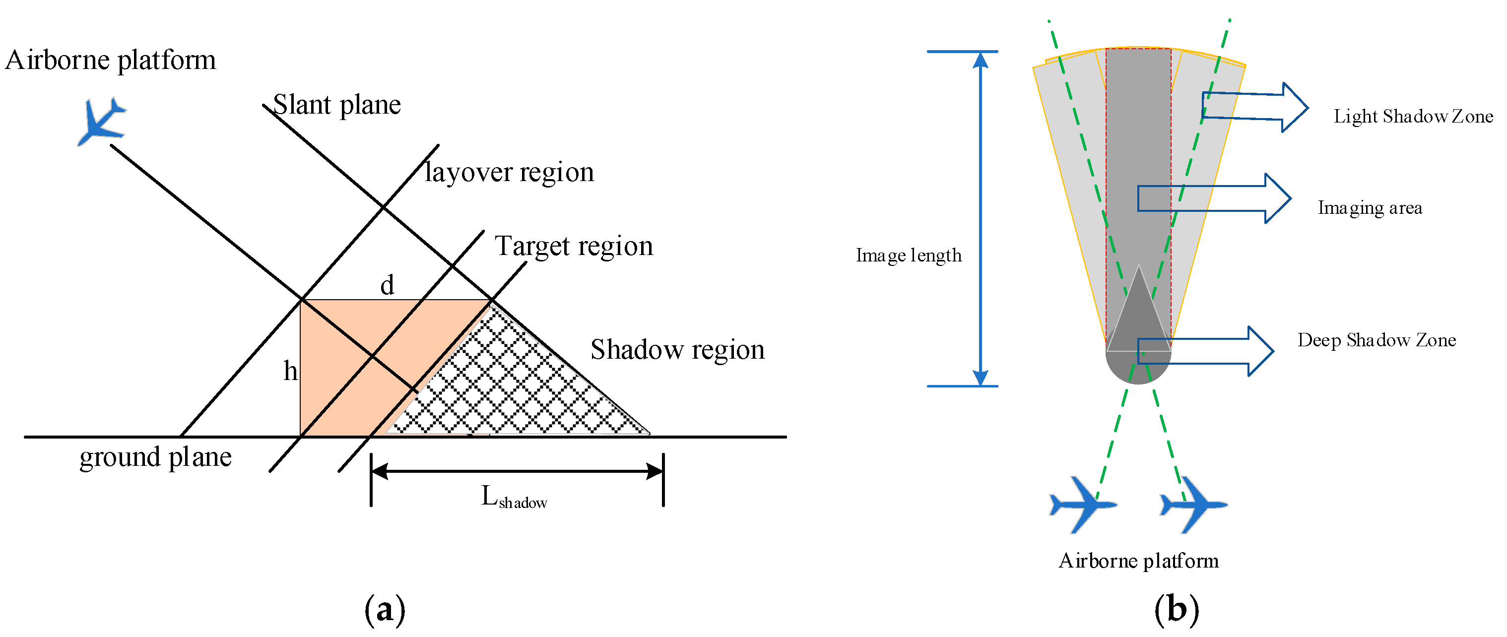
Figure 3.
RCS of a metal plate at different frequency bands.
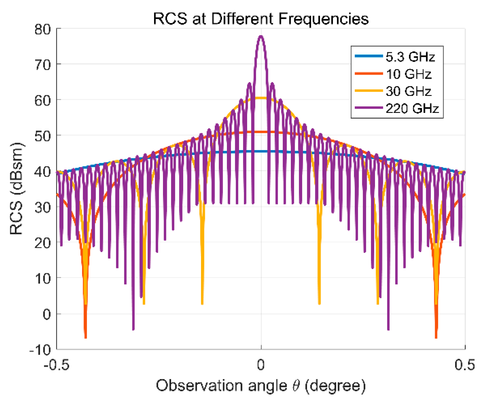
Figure 4.
Geometric relationship between moving target and carrier in oblique plane.
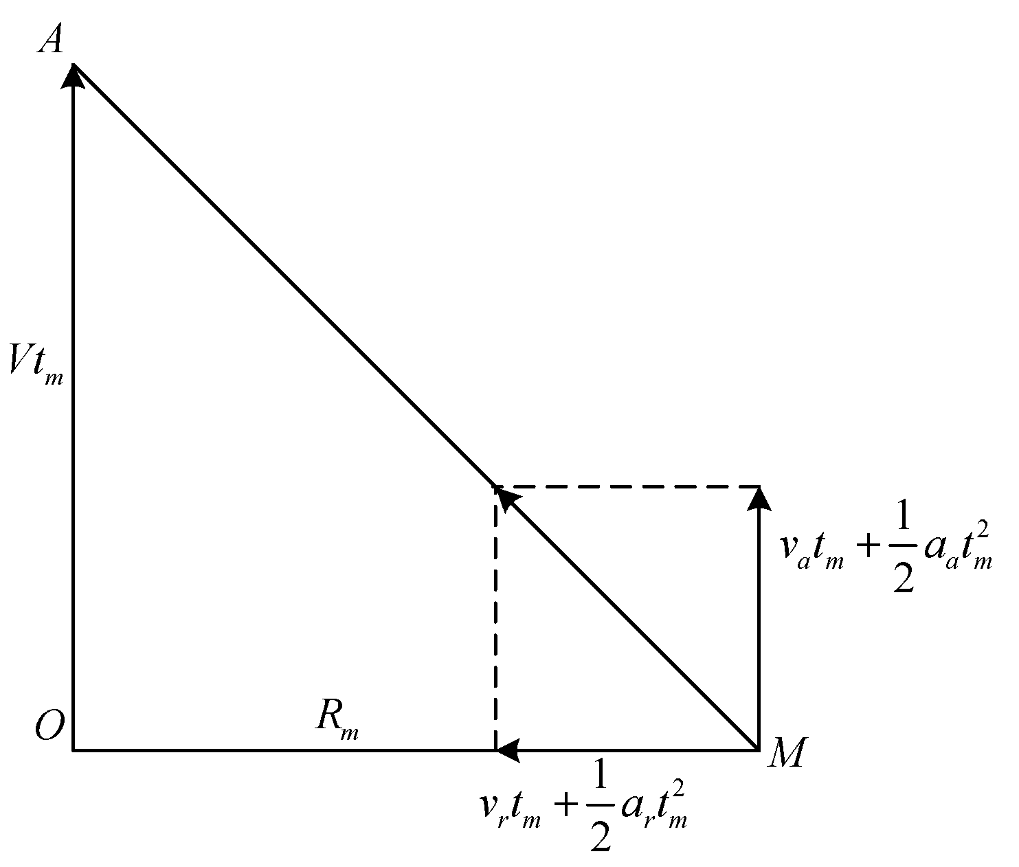
Figure 5.
Algorithm flow of this article.
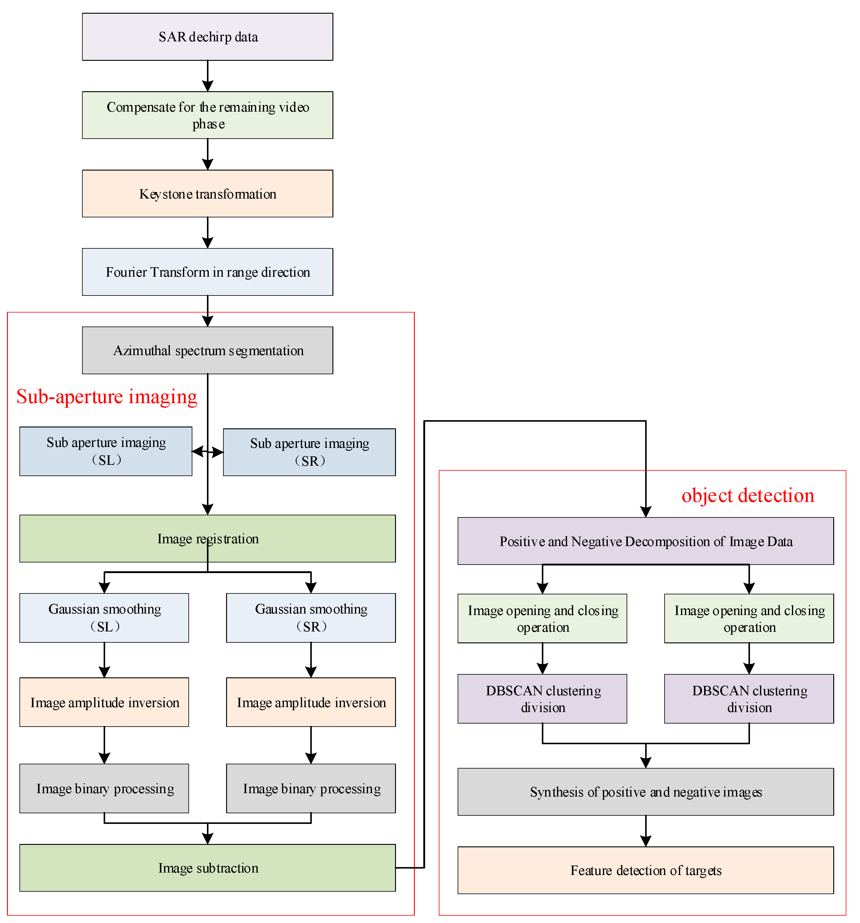
Figure 6.
Point target simulation results. (a) Point target position. (b) Imaging results of point targets. (c) Left sub aperture imaging results. (d) Right sub aperture imaging results. (e) Result of image subtraction.
Figure 6.
Point target simulation results. (a) Point target position. (b) Imaging results of point targets. (c) Left sub aperture imaging results. (d) Right sub aperture imaging results. (e) Result of image subtraction.
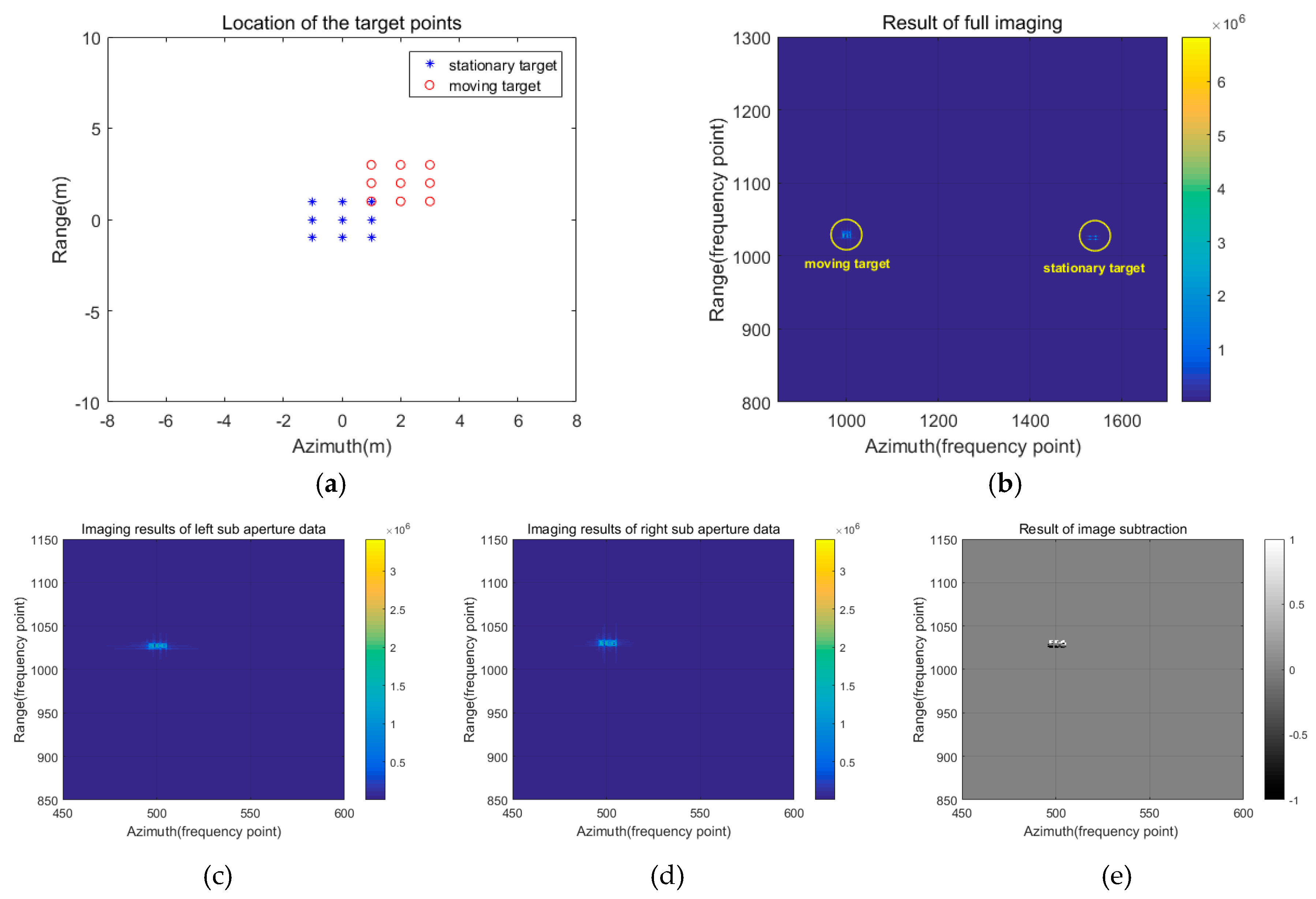
Figure 7.
Simulation results of C-band moving target detection. (a) Location of the targets. (b) Imaging results. (c) Imaging results of moving targets after image subtraction.
Figure 7.
Simulation results of C-band moving target detection. (a) Location of the targets. (b) Imaging results. (c) Imaging results of moving targets after image subtraction.
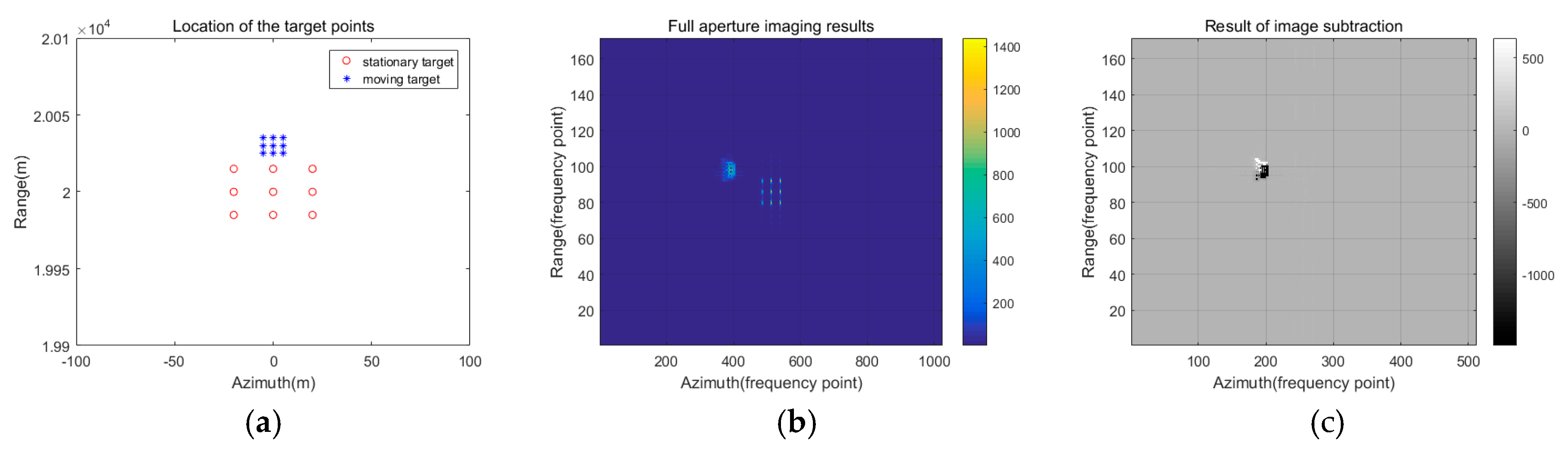
Figure 8.
Imaging results of left and right sub apertures in terahertz video SAR. (a) Imaging results of left sub aperture. (b) Imaging results of right sub aperture.
Figure 8.
Imaging results of left and right sub apertures in terahertz video SAR. (a) Imaging results of left sub aperture. (b) Imaging results of right sub aperture.
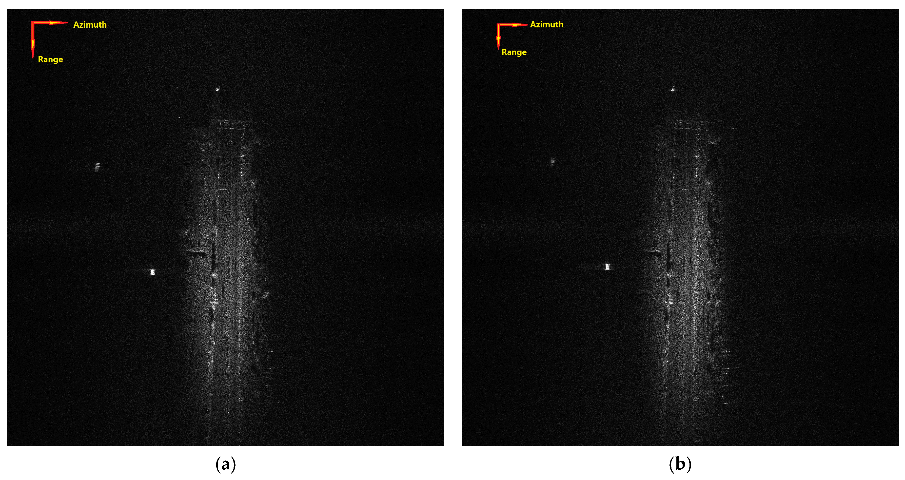
Figure 9.
Result of image subtraction.
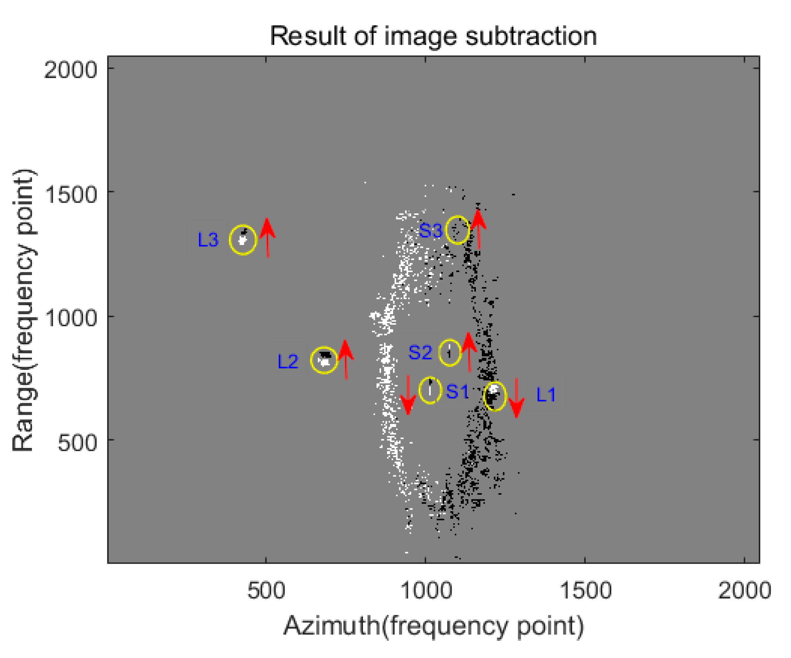
Figure 10.
Composite image after clustering.
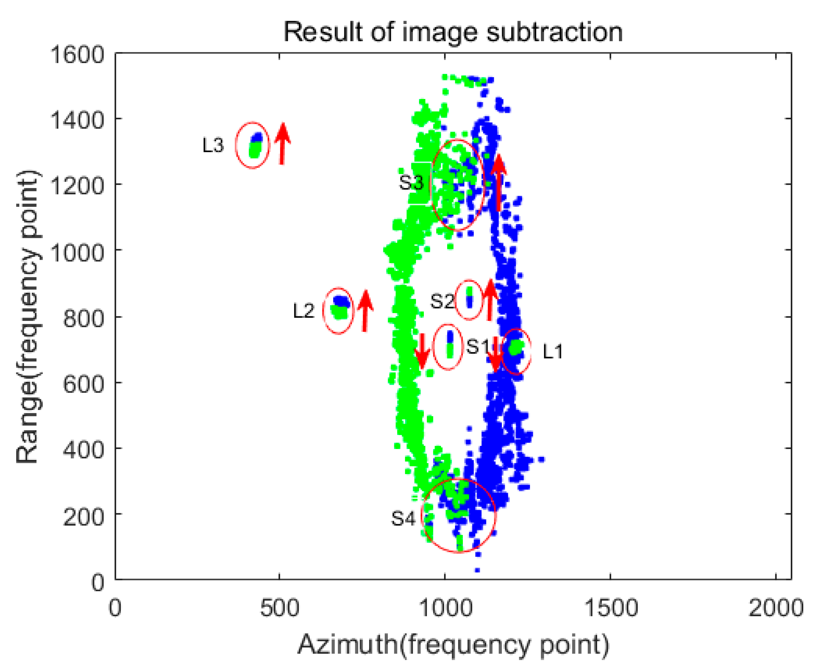
Figure 11.
Composite image after clustering.
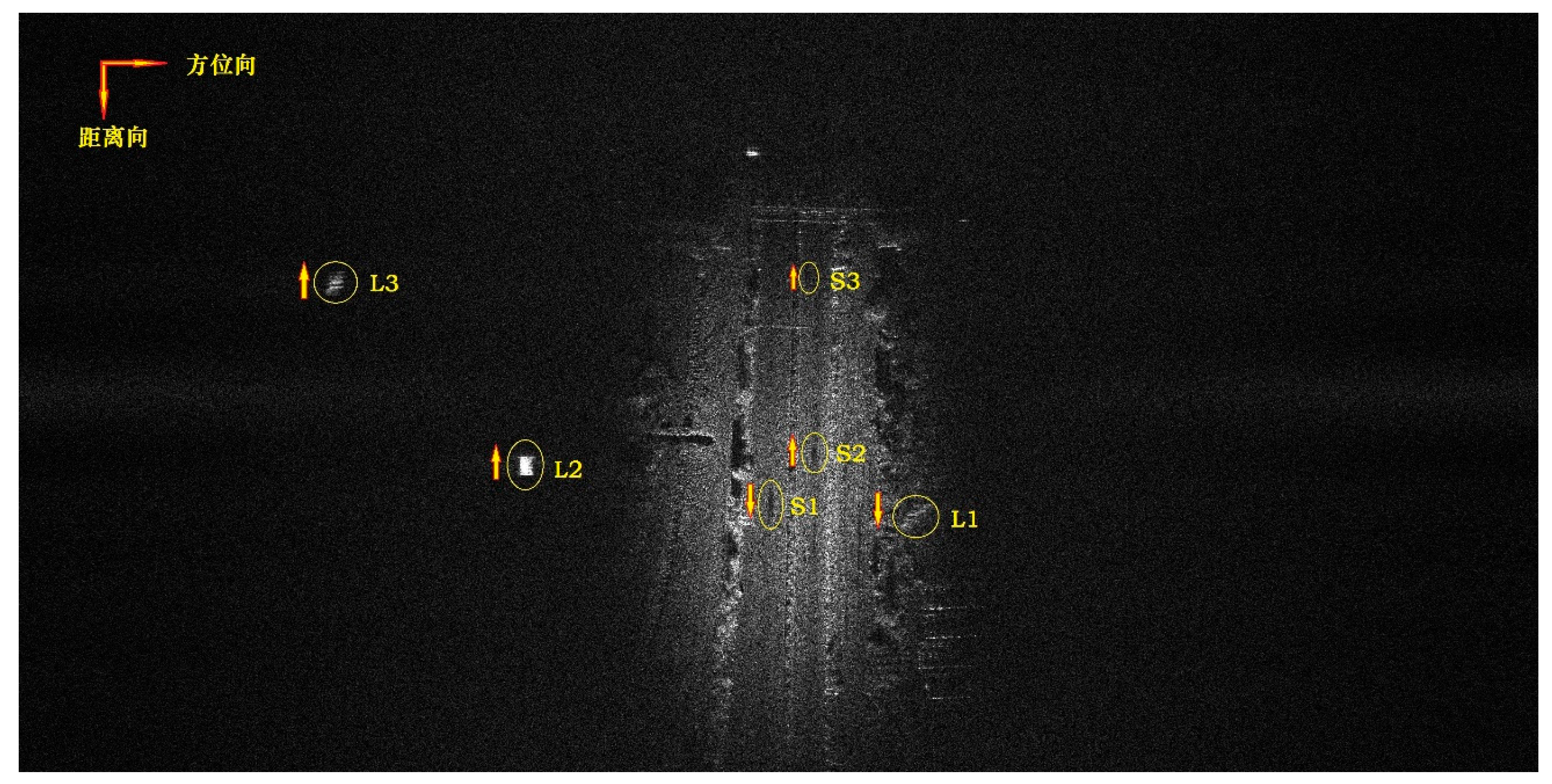
Figure 12.
Detection of moving targets under complex road conditions in strip mode. (a) Detection results of image subtraction under complex road conditions. (b) Detection results in images under complex road conditions.
Figure 12.
Detection of moving targets under complex road conditions in strip mode. (a) Detection results of image subtraction under complex road conditions. (b) Detection results in images under complex road conditions.
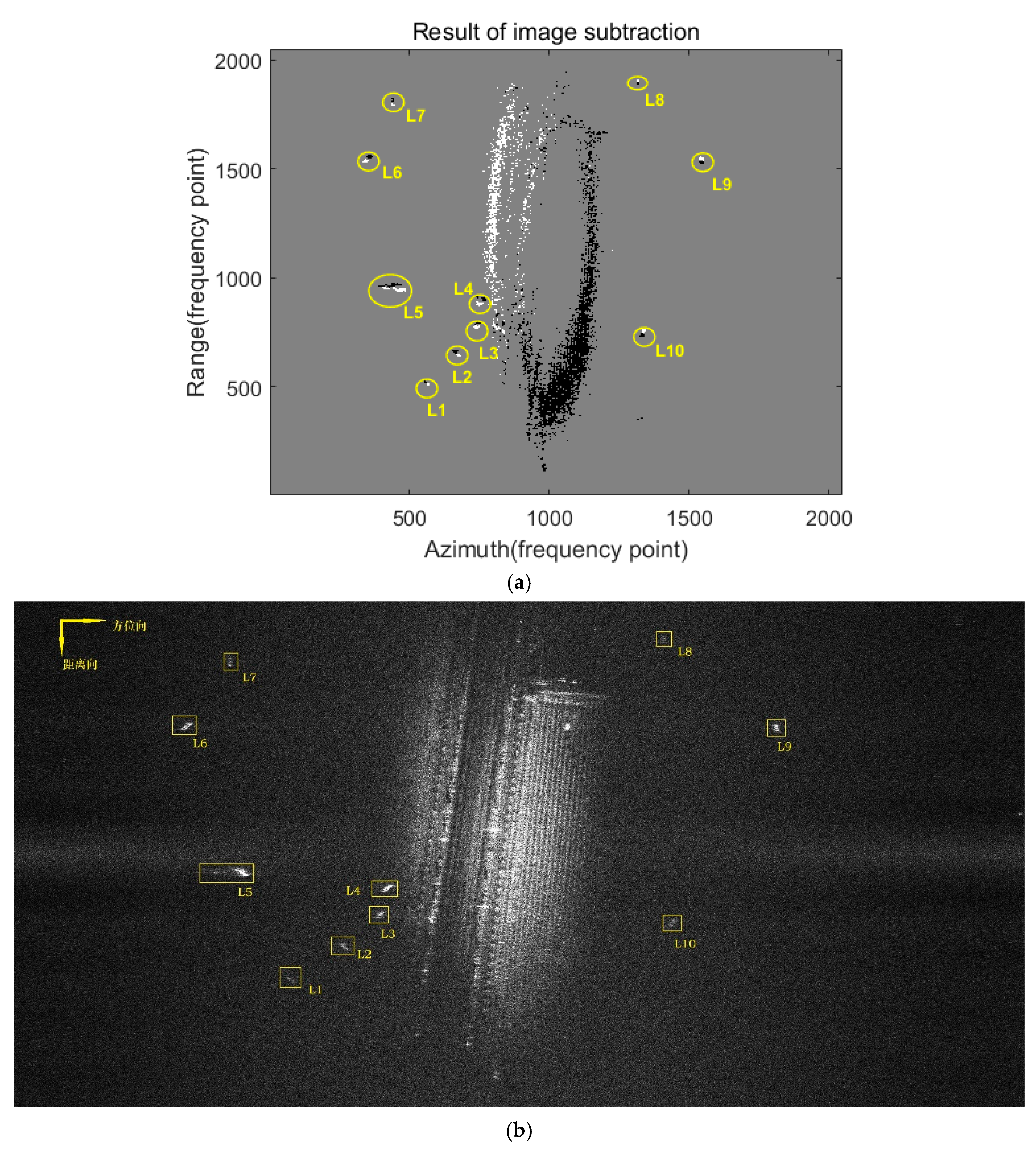
Figure 13.
Detection of Moving Targets in Linear Spotlight Mode. (a) Optical images of the road surrounding the sundial. (b) Detection results after image subtraction in spotlight mode. (c) Detection results in full image in spotlight mode.
Figure 13.
Detection of Moving Targets in Linear Spotlight Mode. (a) Optical images of the road surrounding the sundial. (b) Detection results after image subtraction in spotlight mode. (c) Detection results in full image in spotlight mode.
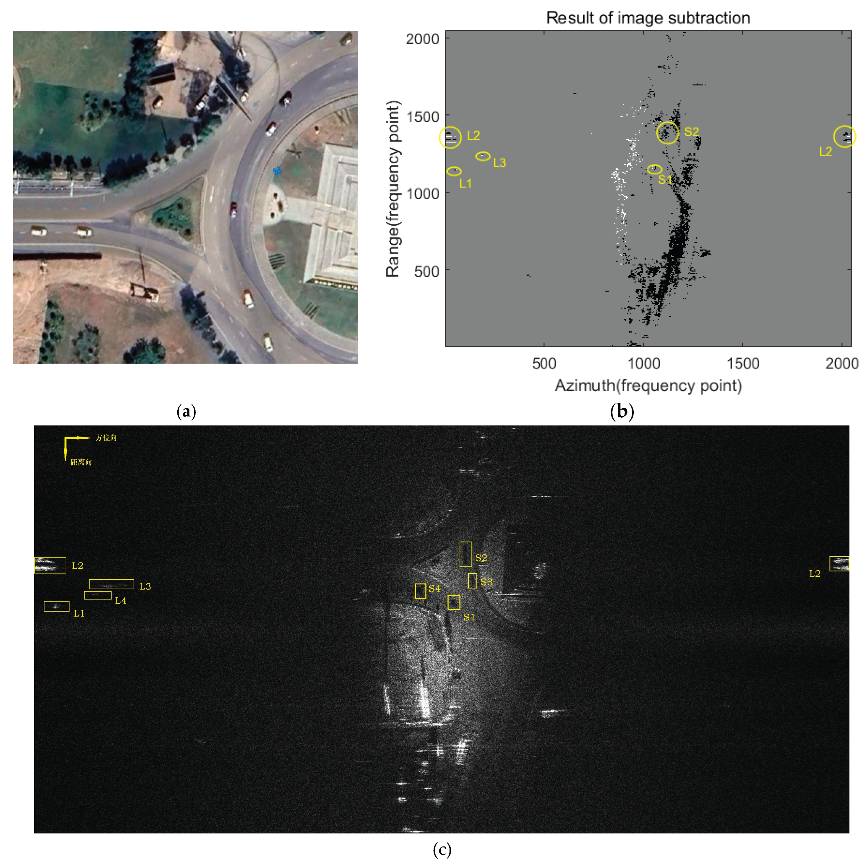
Table 2.
Main parameters of terahertz video SAR imaging scenarios.
| parameter | value | unit | parameter | value | unit |
|---|---|---|---|---|---|
| carrier frequency | terahertz | - | slant range | 2500 | m |
| Imaging mode | strip | - | flying height | 1000 | m |
| Synthetic aperture length | 40 | m | Range Bandwidth | 900 | MHz |
| Range sampling rate | 400 | MHz | Azimuth sampling rate | 16 | kHz |
Disclaimer/Publisher’s Note: The statements, opinions and data contained in all publications are solely those of the individual author(s) and contributor(s) and not of MDPI and/or the editor(s). MDPI and/or the editor(s) disclaim responsibility for any injury to people or property resulting from any ideas, methods, instructions or products referred to in the content. |
© 2026 by the authors. Licensee MDPI, Basel, Switzerland. This article is an open access article distributed under the terms and conditions of the Creative Commons Attribution (CC BY) license (http://creativecommons.org/licenses/by/4.0/).
Copyright: This open access article is published under a Creative Commons CC BY 4.0 license, which permit the free download, distribution, and reuse, provided that the author and preprint are cited in any reuse.


