Submitted:
05 January 2026
Posted:
06 January 2026
You are already at the latest version
Abstract
This work presents the development, modelling, integration, and validation of a flight control system (FCS) designed to convert a piloted ultra-light aircraft (ULM) into a fully autonomous vertical take-off and landing (VTOL) unmanned aerial vehicle (UAV), while maintaining Optionally Piloted Vehicle (OPV) capability. Unlike conventional ULM autopilots focused mainly on stabilization or pilot assistance, the proposed architecture enables full mission-phase autonomy, including take-off, hover, transition, cruise, approach, and landing, and ensures safe coexistence between autonomous and manual control pathways. A high-fidelity simulation framework was developed in MATLAB/Simulink and Simscape, integrating aerodynamic models derived from XFLR5 and VSPAERO, structural and inertia modelling, propulsion and energy-storage dynamics, and the complete cascaded control structure. Hardware-in-the-Loop (HIL) experiments were conducted using a modular test bench featuring a six-degree-of-freedom force–moment balance and an internal-combustion propulsion unit, allowing the injection of realistic vibration signatures into the control loop. Results demonstrate robust tracking of attitude and angular-rate commands under significant perturbations and AHRS measurement noise, indicating the system’s readiness for initial VTOL flight tests and subsequent transition-mode refinement. Overall, the paper details the control architecture, modelling methodology, simulation environment, and preliminary ground-testing efforts supporting advancement toward Technology Readiness Level 6.
Keywords:
UL
; UAV
; flight control system
; autonomous system
1. Introduction
Ultra-light aircraft (ULM) platforms are increasingly considered for unmanned applications due to their low operating costs, mechanical simplicity, and favorable regulatory status[1,2,3]. Nevertheless, transforming a piloted ULM into a fully autonomous unmanned aircraft vehicle (UAV) introduces several significant challenges at the flight-control level. Existing ULM autopilot systems generally provide only basic in-flight augmentation functions—such as heading hold, altitude hold, climb and descent rate control, or stability enhancement—and are not designed to support the full mission envelope required for autonomous operation. In particular, they lack the robust guidance, navigation, and control (GNC) capabilities necessary for autonomous take-off, landing, and contingency management, all of which are essential components of a certifiable UAV flight profile [1,2].
In this context, the present work focuses on the design and integration of a comprehensive flight control system (FCS) that enables fully autonomous operation of an ultra-light aircraft originally intended for piloted use. The proposed system extends conventional ULM autopilot functionality by incorporating all flight phases—ranging from ground roll and rotation to approach, flare, and landing—within a unified, sensor-driven guidance and control framework. A further distinguishing feature of the platform is its Vertical Take-Off and Landing (VTOL) capability, achieved through the hybridization of the original fixed-wing airframe with a multirotor propulsion module to support low-speed control, transition maneuvers, and safe envelope expansion.
Furthermore, the target platform must remain an Optionally Piloted Vehicle (OPV) as required by the end user. Accordingly, the proposed FCS is designed to operate in parallel with the original manual control chain, ensuring that autonomous functionalities can be engaged and disengaged safely without compromising the aircraft’s native mechanical controls. This requirement motivates the integration of redundant actuation pathways, electromechanical disengagement mechanisms, and safety-critical switching logic [4], thereby guaranteeing that the human pilot retains full authority whenever necessary.
The objective of this article is to present the architecture, design methodology, and implementation strategy of the developed flight control system, with emphasis on its ability to transform a conventional ULM into a fully autonomous, VTOL-capable, and optionally piloted unmanned aircraft.
Related Work
Research on converting piloted light aircraft into unmanned or optionally piloted platforms has expanded significantly over the past decade, driven by both emerging operational demands and advances in autonomous flight-control architectures. Traditional autopilot systems for ultra-light and general-aviation aircraft have been developed primarily as pilot-assistance tools, offering functions such as attitude stabilization, altitude hold, heading or navigation tracking, and basic envelope protection. These systems are fundamentally oriented toward human–machine cooperation and do not incorporate the autonomous guidance and control layers necessary for fully pilotless operation. Consequently, they lack key capabilities for autonomous take-off, landing, taxiing, contingency handling, and mission-level decision making—functionalities that are standard components of advanced UAV avionics.
Parallel developments in unmanned aviation have demonstrated substantial progress in full-authority autopilot systems for fixed-wing UAVs, incorporating robust lateral–longitudinal control laws, energy-aware trajectory planning, and advanced sensor-fusion schemes integrating INS/GNSS, vision-based navigation, and radar altimetry[1,3]. However, the majority of these solutions are conceived for airframes purpose-built for unmanned operation, in which actuation pathways, servo authority, and structural interfaces are intrinsically optimized for autonomous control. Consequently, direct transfer of such UAV-oriented autopilot architectures to converted manned ULM platforms is constrained by fundamental differences in mechanical layout, actuation design, and the need to ensure seamless coexistence with human-operated control systems.
Research on Optionally Piloted Vehicles (OPVs) has identified several viable strategies for integrating autonomous control systems with existing manual command pathways[4,5]. Common approaches include the use of parallel actuation channels, electromechanical clutch mechanisms that enable safe engagement and disengagement of autonomous functions, supervisory switching logic, and fault-tolerant architectures designed to preserve pilot authority under degraded operating conditions. Although these studies establish general design principles, they predominantly address larger platforms—such as general-aviation aircraft, experimental research testbeds, or military trainer configurations—thus leaving a notable gap in OPV methodologies specifically adapted to ultra-light aircraft, where limitations in weight, available power, and structural volume impose significantly stricter integration constraints.
In the field of VTOL hybrid aircraft, a substantial body of literature addresses multirotor–fixed-wing configurations, transition dynamics, and controller blending across hover, transition, and forward-flight regimes[8,9]. While such architectures are widely explored in the context of small unmanned aerial systems, considerably fewer studies examine their applicability to manned-scale ultralight aircraft. This gap highlights several persisting challenges, including the management of distributed propulsion, the mitigation of cross-coupling effects between rotor-borne and fixed-wing control loops, and the assurance of safe and repeatable transitions under varying aerodynamic conditions.
Autonomous take-off and landing (ATOL) research consistently highlights the necessity of tightly integrated guidance, navigation, and control (GNC) subsystems encompassing precision navigation through GNSS/INS fusion, dedicated flare and energy-management algorithms, terrain-sensing capabilities, and envelope-protection logic [1,10]. Although these algorithms are well established within the UAV domain, relatively few implementations demonstrate their integration in OPV or ULM-conversion contexts, where autonomous actuators must coexist with manual control surfaces and transitions between control regimes must adhere to stringent safety constraints.
Overall, existing research provides a solid foundation in ULM autopilot design, UAV autonomous control algorithms, OPV integration strategies, and VTOL hybrid aircraft architecture. However, the literature provides limited guidance on the combined challenge addressed in this study: the development of a fully autonomous, VTOL-capable, optionally piloted ultra-light aircraft that integrates a complete, multi-phase GNC stack with dual-control-path safety mechanisms. The present work aims to bridge this gap.
Figure 1.
The current state of development of ULM-class aircraft at AVI Aircraft.
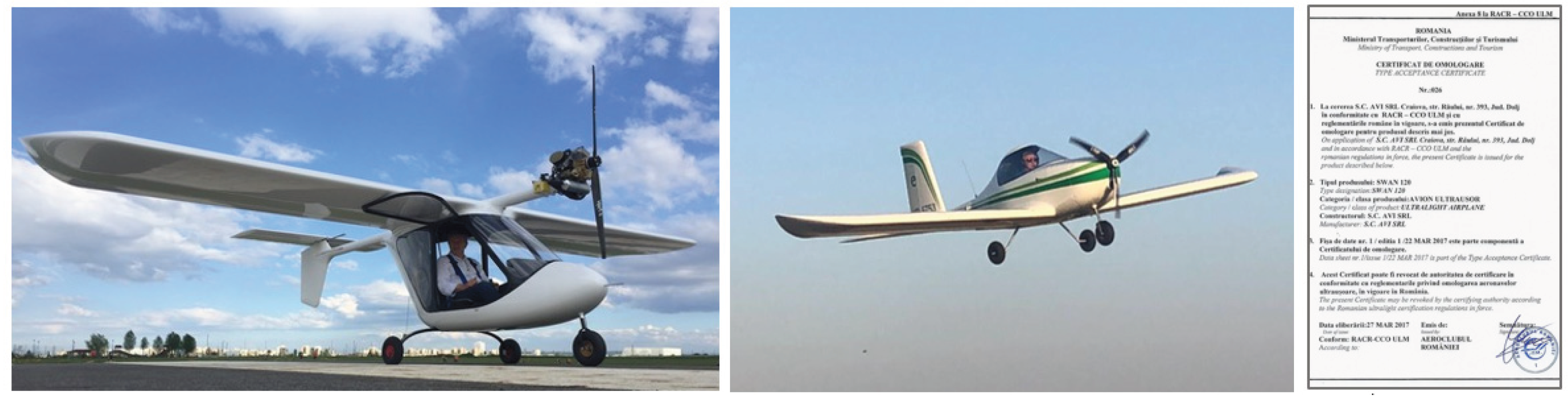
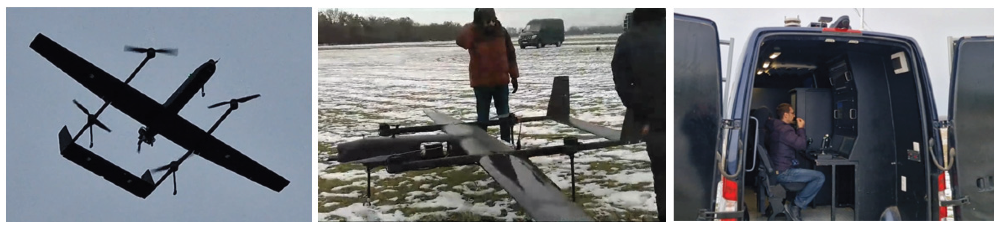
The team contributing to this work is multidisciplinary, comprising senior engineers from AVI Aircraft—a Romanian company specialized in the design and production of ultra-light aircraft—and researchers from INCAS, the National Institute for Aerospace Research of Romania. AVI Aircraft has an established portfolio of certified ULM platforms operating on the European market, while INCAS provides extensive expertise in the development of advanced unmanned aircraft systems (UAS), including both UAVs and ground control infrastructures, validated at high Technology Readiness Levels in complex operational scenarios.
Figure 2.
The current state of development of UAS systems at INCAS.
The joint AVI–INCAS initiative represents the first effort in Romania to achieve pre-operational integration of vertical take-off and landing (VTOL) capability within an optionally piloted aerial system. This development is driven by operational requirements associated with conducting aerial work in non-segregated airspace, envisioned as a cooperative environment in which OPV-class vehicles and fully autonomous UAVs operate concurrently. The targeted system is intended to reach a high level of technological maturity (TRL 6) and to comply with the relevant European regulatory framework, particularly the provisions governing UAV and drone operations within U-space.
2. Materials and Methods
2.1. Mathematical Modeling (VTOL Mode)
Equations of Motion:
- the equations of motion of a rigid body with six degrees of freedom (6-DOF)
- the propulsion element model
- the distribution of forces and moments as a function of each rotor’s position
State-space representation:
where:
- : position in the inertial frame
- : Euler angles
- : linear velocities in the body frame
- : angular velocities of the body
Translational equations of motion:
Rotational equations of motion:
Kinematic equations between angular rates and Euler angles:
Propulsion element model:
Thrust force:
Reaction torque:
Total thrust force:
2.2. Control Structure
A widely adopted strategy for stabilizing aerial vehicles is the use of proportional–integral–derivative (PID) control structures. The following subsection presents the continuous-time and discrete-time formulations of the parallel PID controller.
Continuous time:
Discrete time:
where:
- is the proportional gain.
- is the integral gain.
- is the derivative gain.
- is the first-order derivative filter time constant.
- is the integrator method for computing the integral in discrete-time controller.
- is the integrator method for computing the derivative filter in discrete-time controller.
This control structure can be implemented in a cascaded configuration—comprising an outer loop and an inner loop—to regulate the vehicle’s attitude (roll, pitch), heading (yaw), position (), and altitude (z)[7,8]. In this formulation, the outer-loop controllers act on the position states and the attitude angles (roll, pitch, yaw), while the inner-loop controllers regulate the corresponding rate variables, namely the linear and angular velocities commanded to the aircraft. PID-type cascaded architectures remain widely adopted in aerial-vehicle control due to their intuitive tuning process, practical robustness, and suitability for a broad range of flight conditions [7,12].
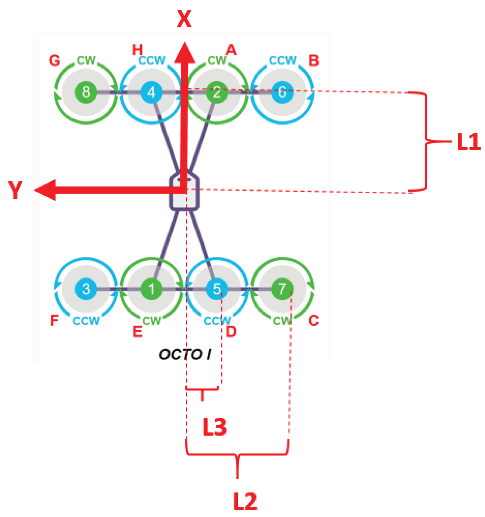
2.3. Control Allocation Matrix for the Octo-I Configuration (in East-North-Down Coordinates)
Figure 3.
L1 = 1.4, L2 = 2.85, L3 = 1.2.
2.4. PMSM Electric Motor Model[13] (Permanent-Magnet Synchronous Motor)
Electrical equilibrium equation:
where:
- is the applied voltage
- is the winding resistance
- is the winding inductance
- is the motor current
- is the back electromotive force (back-EMF)
2.5. Mechanical Equilibrium Equation
where:
- is the rotor moment of inertia
- is the angular speed of the shaft
- is the motor torque
- is the load torque
- is the viscous friction coefficient
2.6. Electric Battery Model
Ideal model:
where:
- is the voltage delivered to the load
- is the open-circuit voltage
- is the internal resistance of the battery
- is the current delivered to the load
Model with state-of-charge (SOC) dependence:
where:
- is the battery capacity (Ah)
- is the consumed current (A)
2.6. Numerical Simulation Framework (Simscape/Matlab Model)
For a detailed analysis of the vehicle’s control behaviour, a comprehensive numerical simulation framework was developed in the MATLAB environment [11]. The framework integrates multiple modelling layers, combining native MATLAB scripts (*.m files) for parameter initialization and specialized computations, Simulink subsystems for implementing the flight-control architecture, and Simscape components for high-fidelity process simulation. The latter includes models of the aerodynamic environment, propulsion system, energy-storage system, and the mechanical and electrical structure of the aircraft. The simulation network also incorporates detailed representations of propulsion elements, battery dynamics, aerodynamic coefficients, actuator geometry, total mass and centre-of-gravity location, as well as the inertia tensor of the structural assembly. These elements interface directly with the Flight Control Unit (FCU) through the implemented cascade control architecture, consisting of outer-loop and inner-loop controllers. The sections that follow describe several of the most relevant components of this framework, including the process-level simulation model, the hierarchical control structure, and the Simscape implementation of a representative propulsion module.
Figure 4.
Process simulation model: propulsion elements, battery models, aerodynamic modeling, mechanical description of the system (propulsor positions, total mass, center-of-gravity location, inertia tensor associated with the mechanical components), and the interface with the FCU (Flight Control Unit) control module.
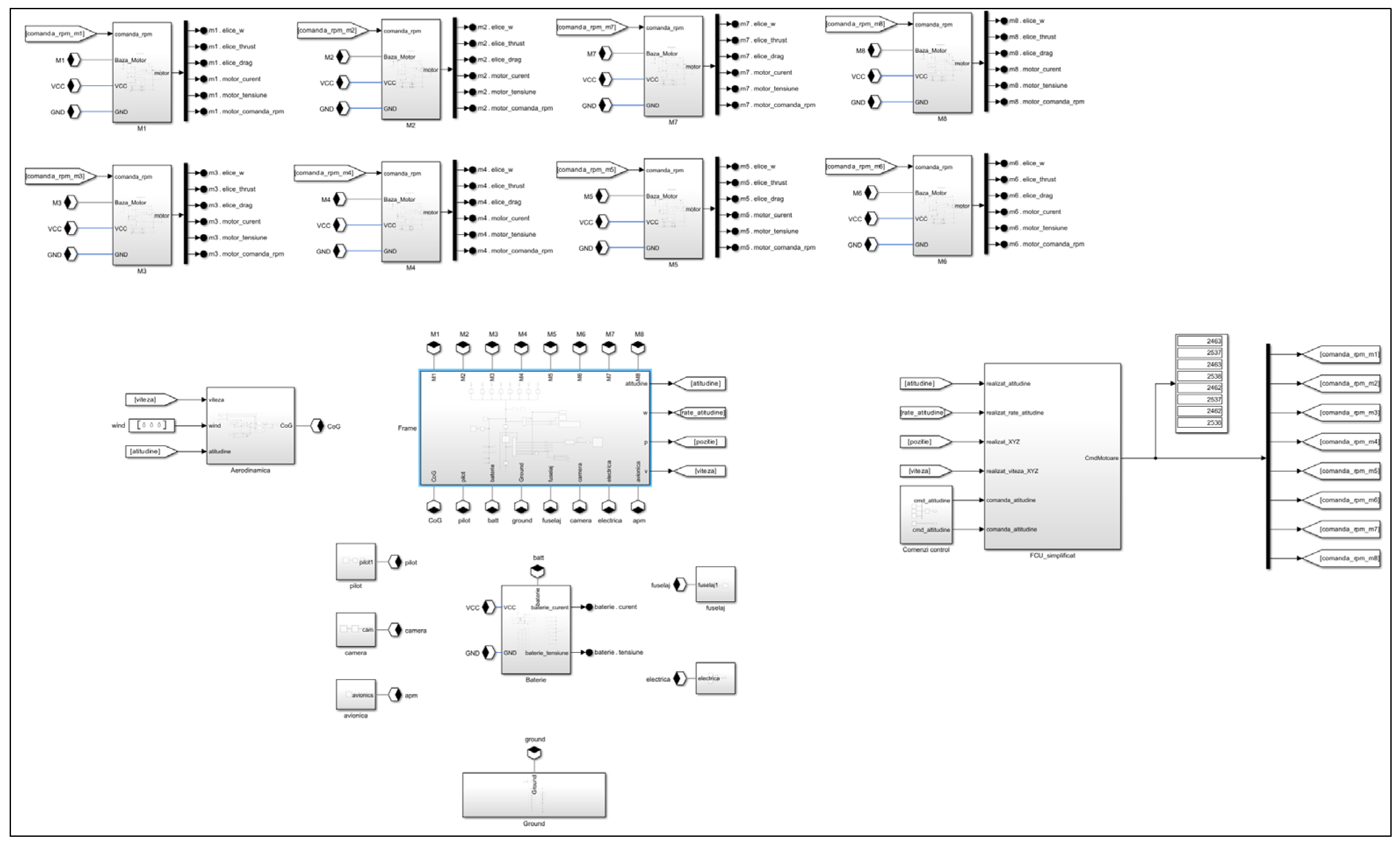
Figure 5.
Cascade control structure (outer/inner loop).
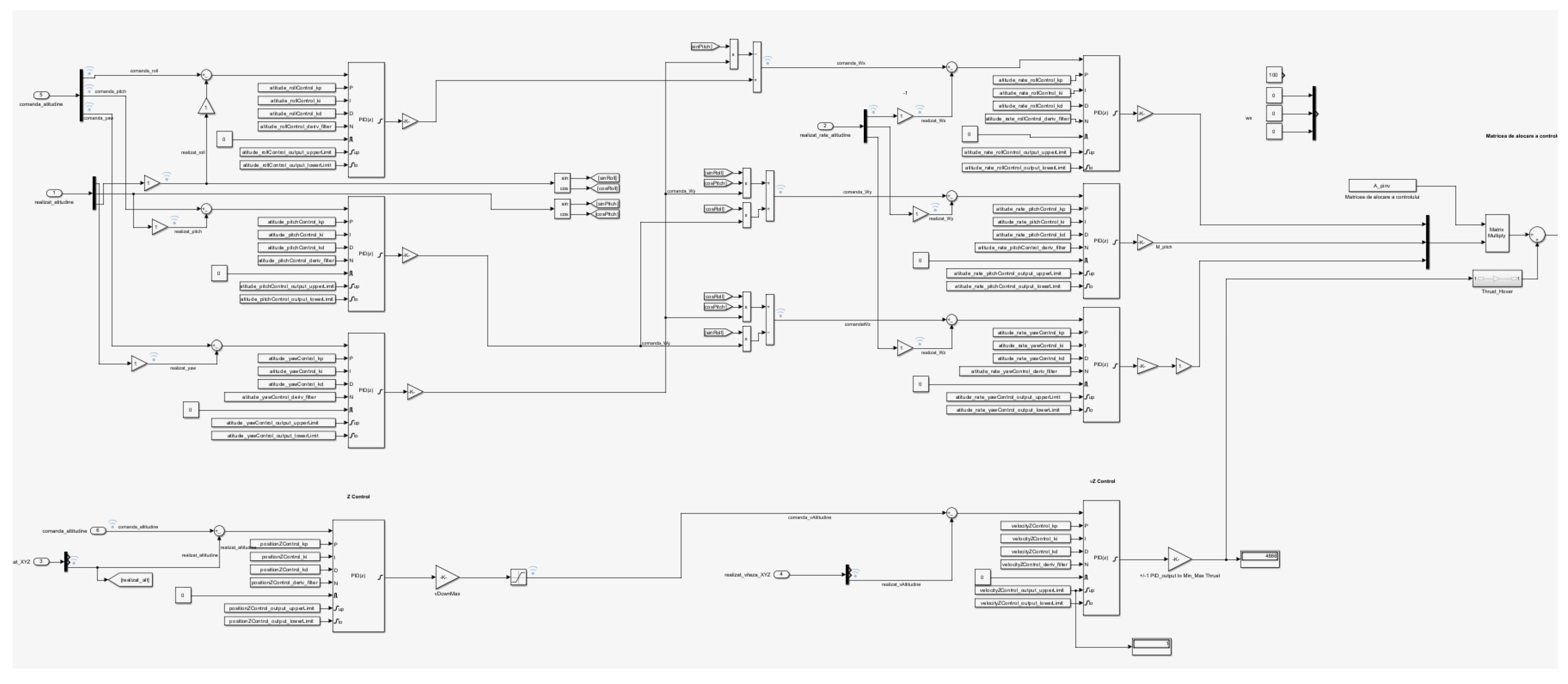
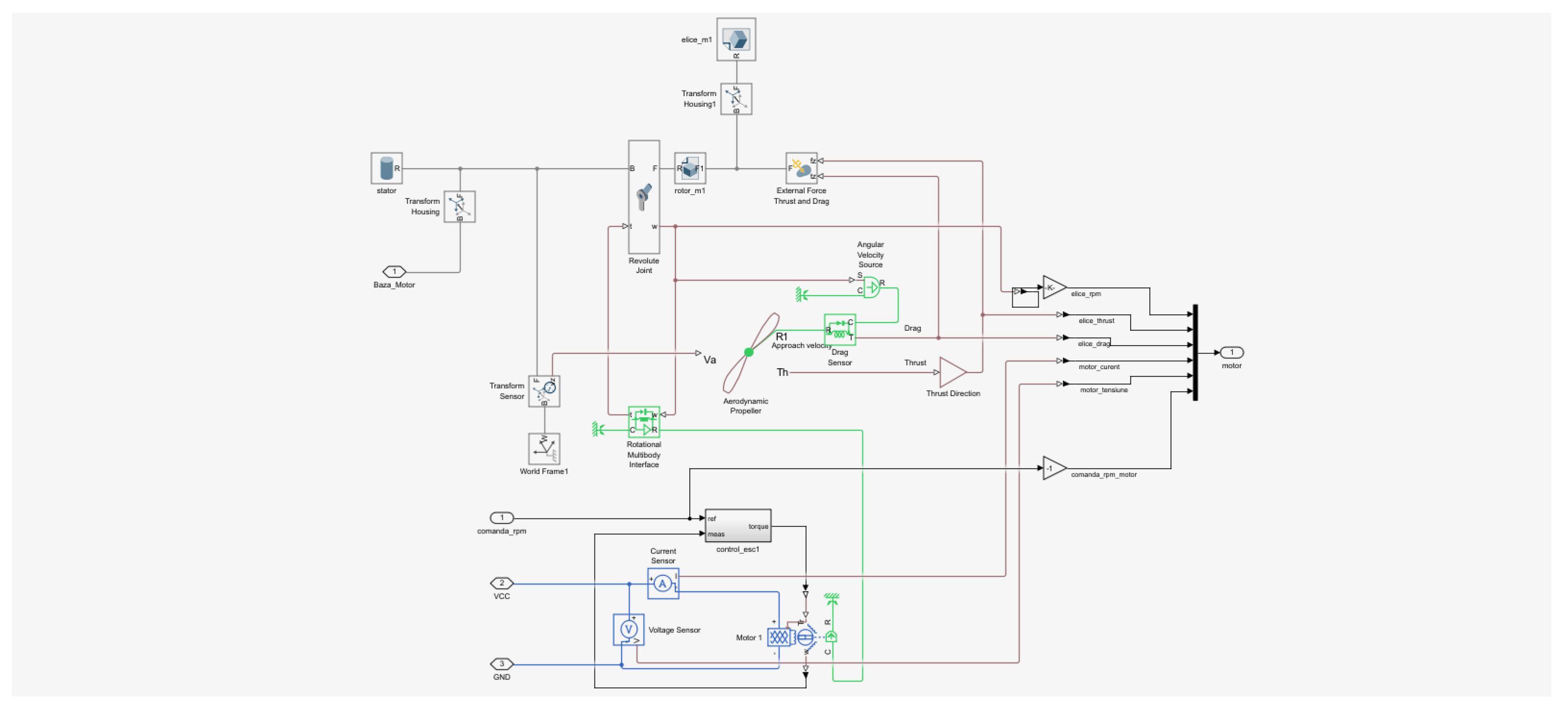
Figure 6.
Simscape detail for a propulsion element.
2.7. Parameters of the Simulation Network
| % Model Parameters of Octo_I_DRAGONFLY | |
| % operation environment | |
| air_temperature = 298; | % Kelvin |
| air_density = 1.225; | % kg/m3 |
| gravity = [0 0 -9.80665]; | % m/s^2 |
| % multirotor propeller | |
| propeller_Diameter = 1.447; | % m |
| propeller_kThrust = 0.0968; | |
| propeller_kPower = 0.0282; | |
| propeller_mass = 0.434; | % kg |
| propeller_center_of_mass = [[0 0 0]; | % m |
| propeller_inertia = [0.061, 0.0007, 0.062]; | % kg*m^2 |
| propeller_product_of_inertia = [[0 0 0]; | % kg*m^2 |
| % multirotor electric motor | |
| motor_max_torque = 64; | % motor_max_torque (Nm) |
| motor_max_power = 23000; | % motor_max_power (W) |
| motor_time_const = 0.010; | % motor_time_const (s) |
| motor_efficiency = 85; | % motor_efficiency (%) |
| motor_efficiency_spd = 1800; | % motor_efficiency_spd (rpm) |
| motor_efficiency_torque = 30; | % motor_efficiency_torque (Nm) |
| motor_rotor_damping = 1e-07; | % motor_rotor_damping (Nm/(rad/s) |
| % battery | |
| nominal_voltage = 100; | % V |
| internal_resistance = 0.002; | % ohm |
| voltage_v1 = 88.8; | % V |
| battery_capacity = 38000; | % Ah |
| charge_AH1 = 19000; | % Amperi.ora |
| batt_temperature = 298.15; | % K |
| fouselage_mass = 100; | % kg |
| frame_mass = 10; | % kg |
| pilot_mass = 70; | % kg |
| battery_mass = 13.2; | % kg |
| combustion engine_mass = 17.6; | % kg |
| fuel_tank = [0.304 0.304 0.304]; | % 28l / 21kg |
The mathematical model was parameterized using aerodynamic data—specifically aerodynamic coefficients and stability derivatives—obtained from dedicated simulations employing three-dimensional panel methods and the Vortex Lattice Method (VLM), conducted with XFLR5 and VSPAERO. The mechanical properties of the system, including mass distribution, moments of inertia, and center-of-gravity location, were derived from concrete data corresponding to existing ULM aircraft that have not yet undergone VTOL conversion. For components specific to the VTOL configuration, where physical measurements are not currently available, parameterization was performed using values extracted from the CAD design models developed in CATIA.
Figure 7.
Aerodynamic analysis in fixed-wing flight regime.
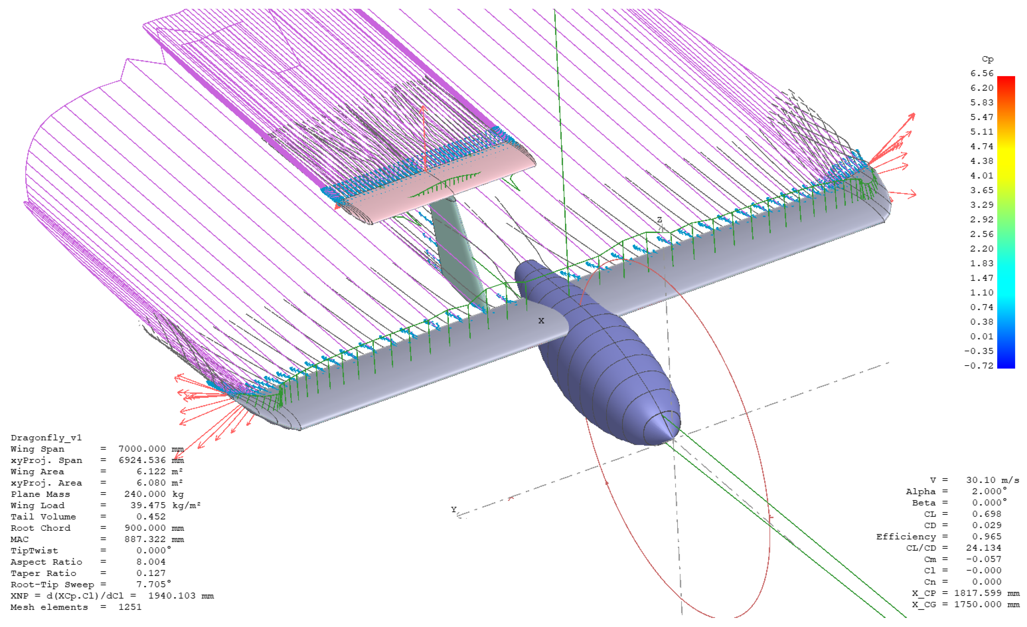
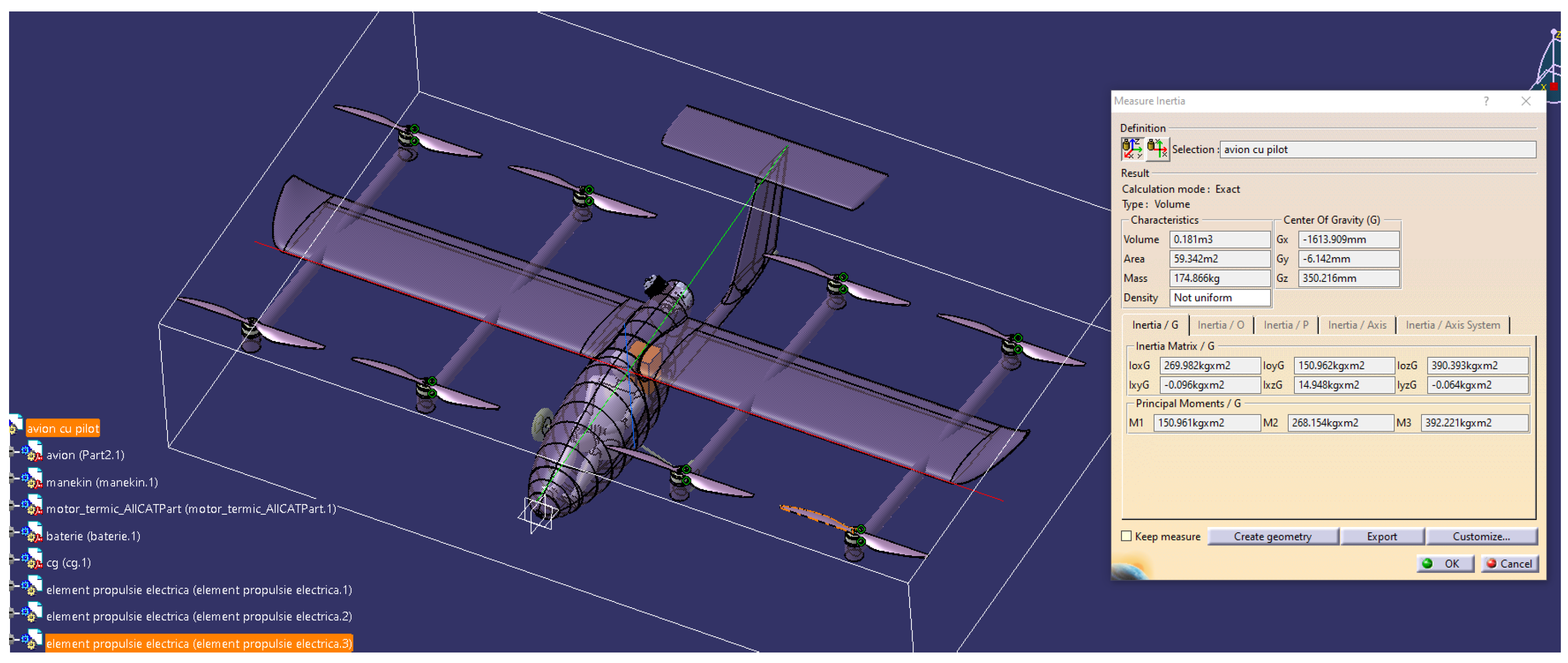
Figure 8.
Mechanical design: determination of the mass, center of gravity, and inertia moments.
The software component of the system was developed with an emphasis on scalability and modular integration of future specialised functionalities. The core implementation is written in C++ and follows an object-oriented (OOP) design philosophy, enabling clear abstraction of subsystems and facilitating maintainability. In its current configuration, the control laws are implemented using proportional–integral–derivative (PID) structures; however, the architecture allows these algorithms to be readily replaced or extended with alternative control strategies, depending on the requirements of subsequent research activities or targeted operational scenarios.
Figure 9.
System software architecture: (a) major system components, (b) the state machine associated with the FMU module.
Figure 9.
System software architecture: (a) major system components, (b) the state machine associated with the FMU module.
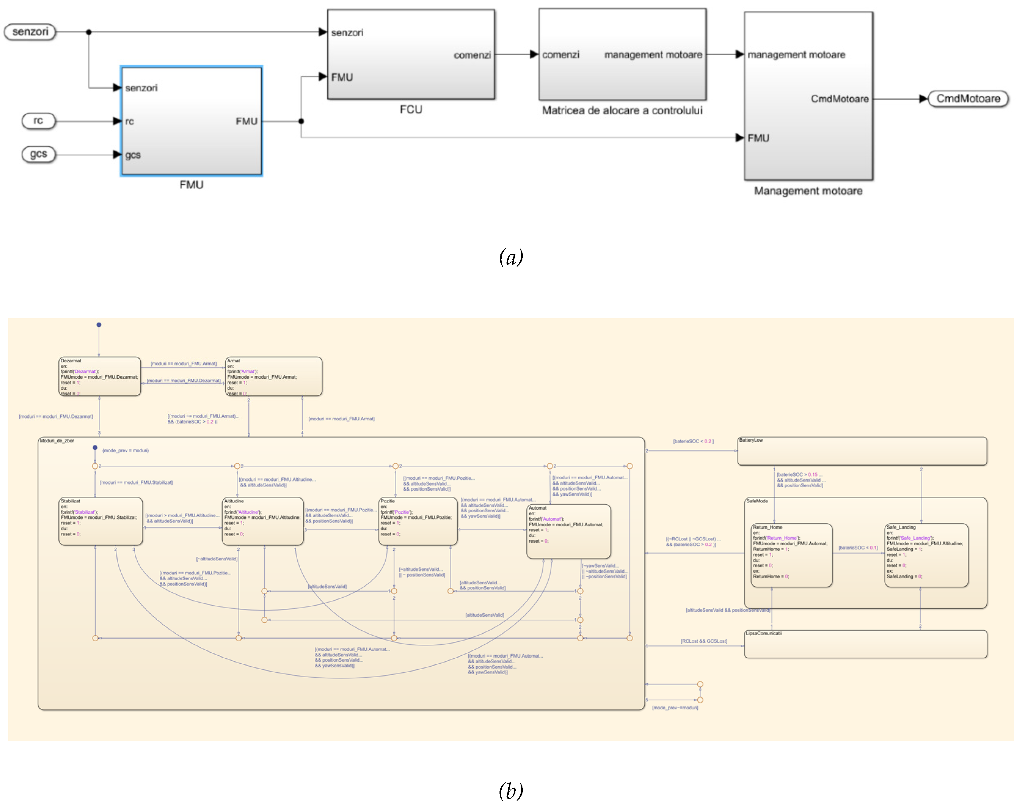
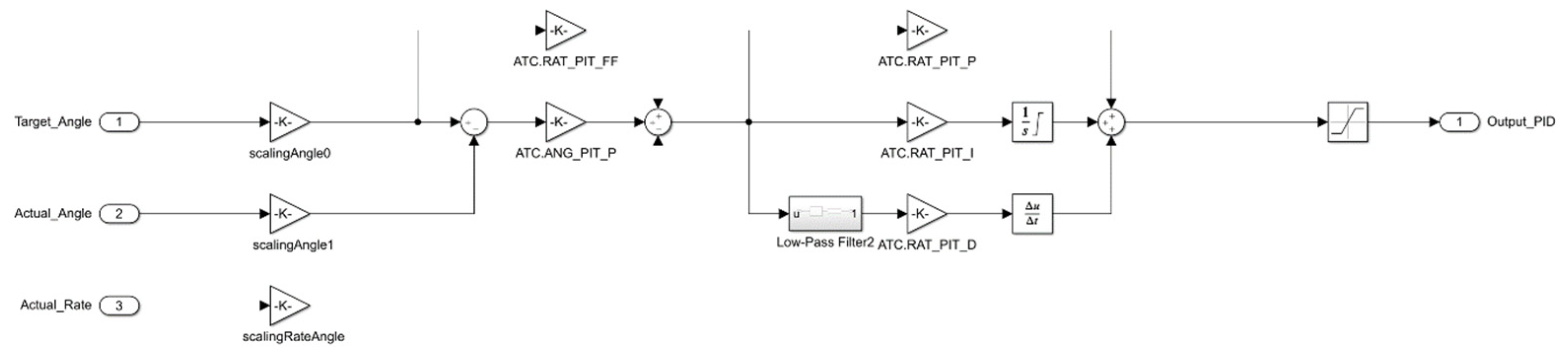
Figure 10.
Multirotor inner/outer control loop.
3. Results
3.1. DragonFly Model, Version 1 – VTOL Octocopter Configuration
In the initial experimental phase, the mathematical model was executed within the MATLAB simulation environment. A representative flight profile was defined, encompassing take-off, stabilization at the prescribed altitude, steady-level flight with a sequence of maneuvering phases, and landing. This phase aimed to validate the integrity and consistency of the simulation framework, assess the dynamic behavior of the individual subsystems under representative flight conditions, and generate time-domain simulation results. These results were subsequently compared with steady-state estimates obtained during the preliminary design phase, providing an initial verification of model fidelity and control system performance.
For intuitive visualization and qualitative assessment of the simulation outcomes, a three-dimensional animated model of the aerial vehicle was developed and integrated into the simulation framework, enabling real-time observation of the vehicle’s motion and attitude during the execution of flight scenarios.
Figure 11.
3D animated model of the vehicle in the simulation environment.
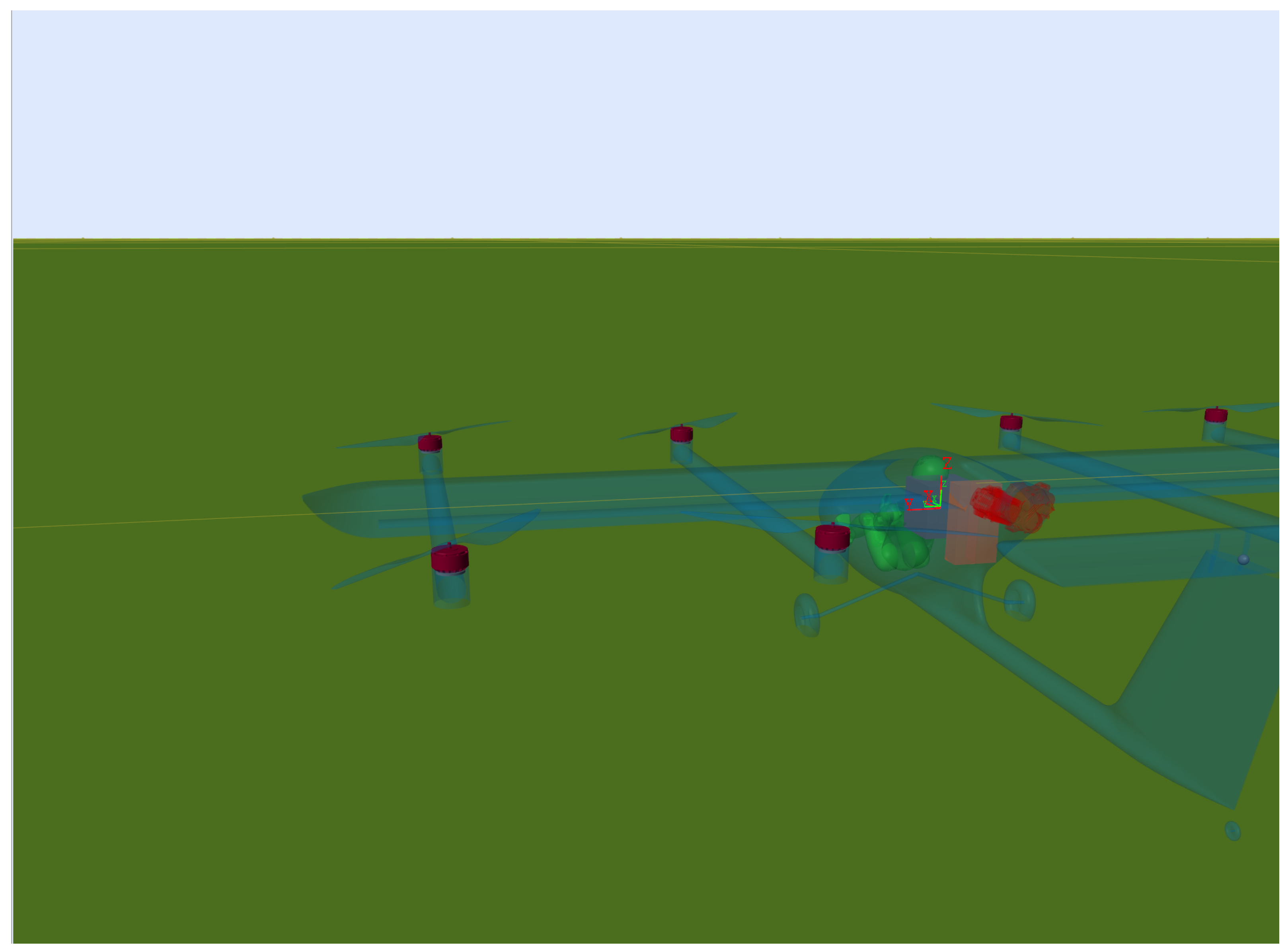
Figure 12.
Operating cycle diagram of the system.
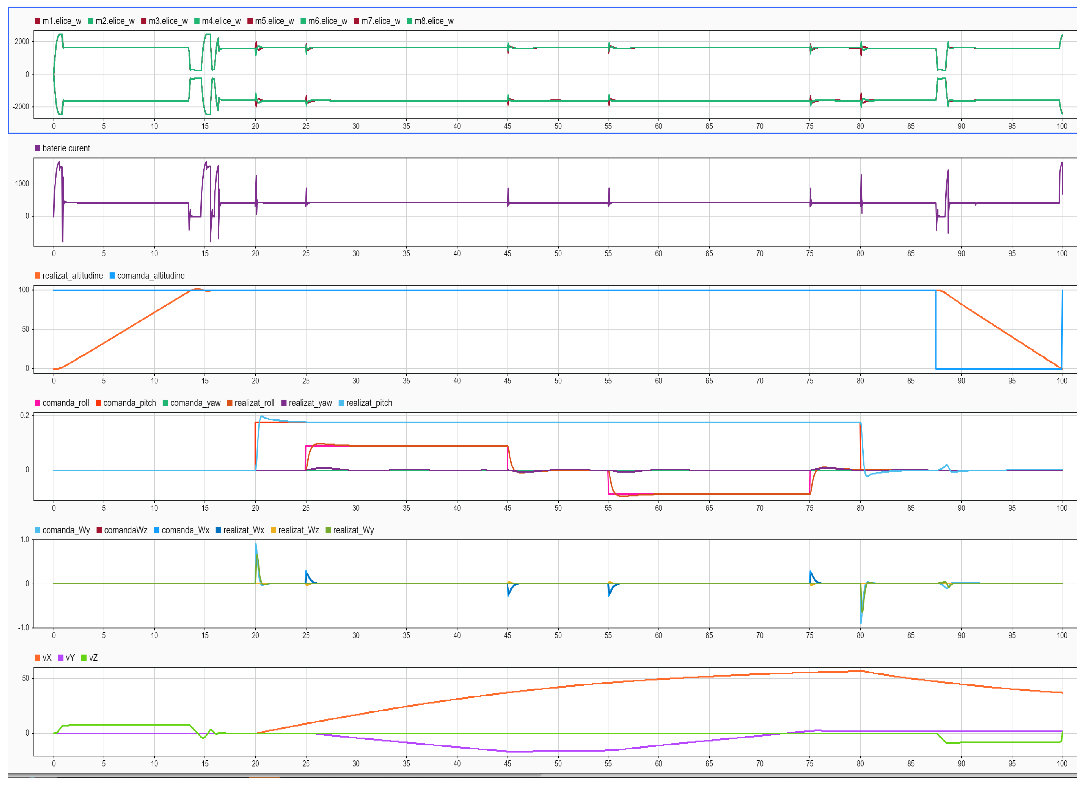
Figure 13.
Time evolution of the rotational speeds (RPM) of the propulsion units.
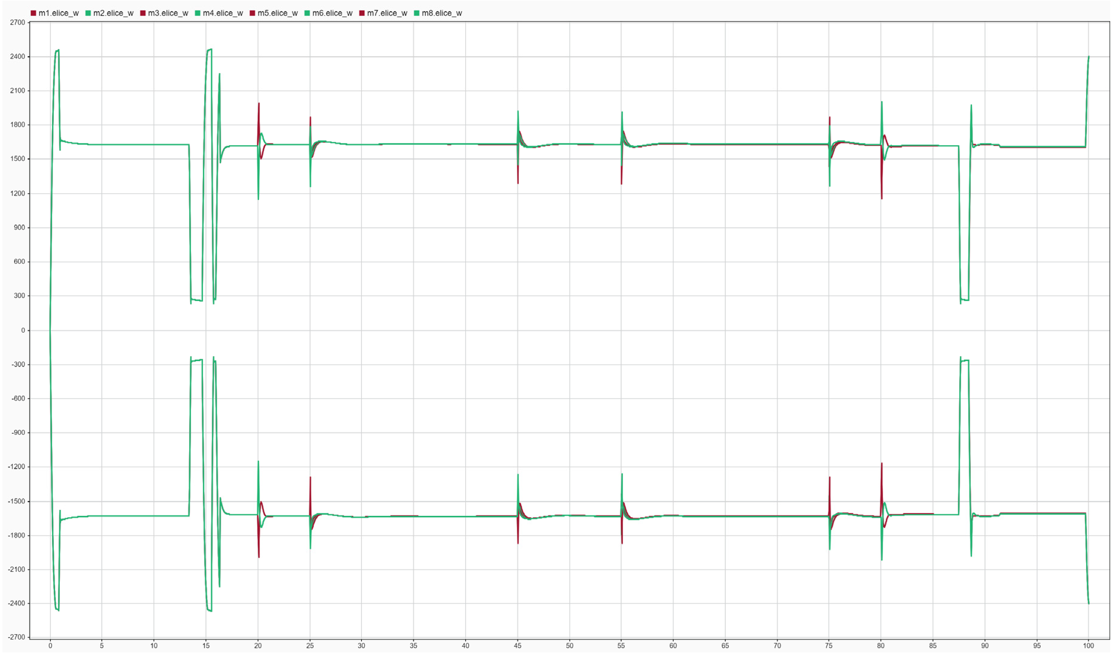
Figure 14.
Instantaneous current (A) profile required to execute the flight maneuvers.
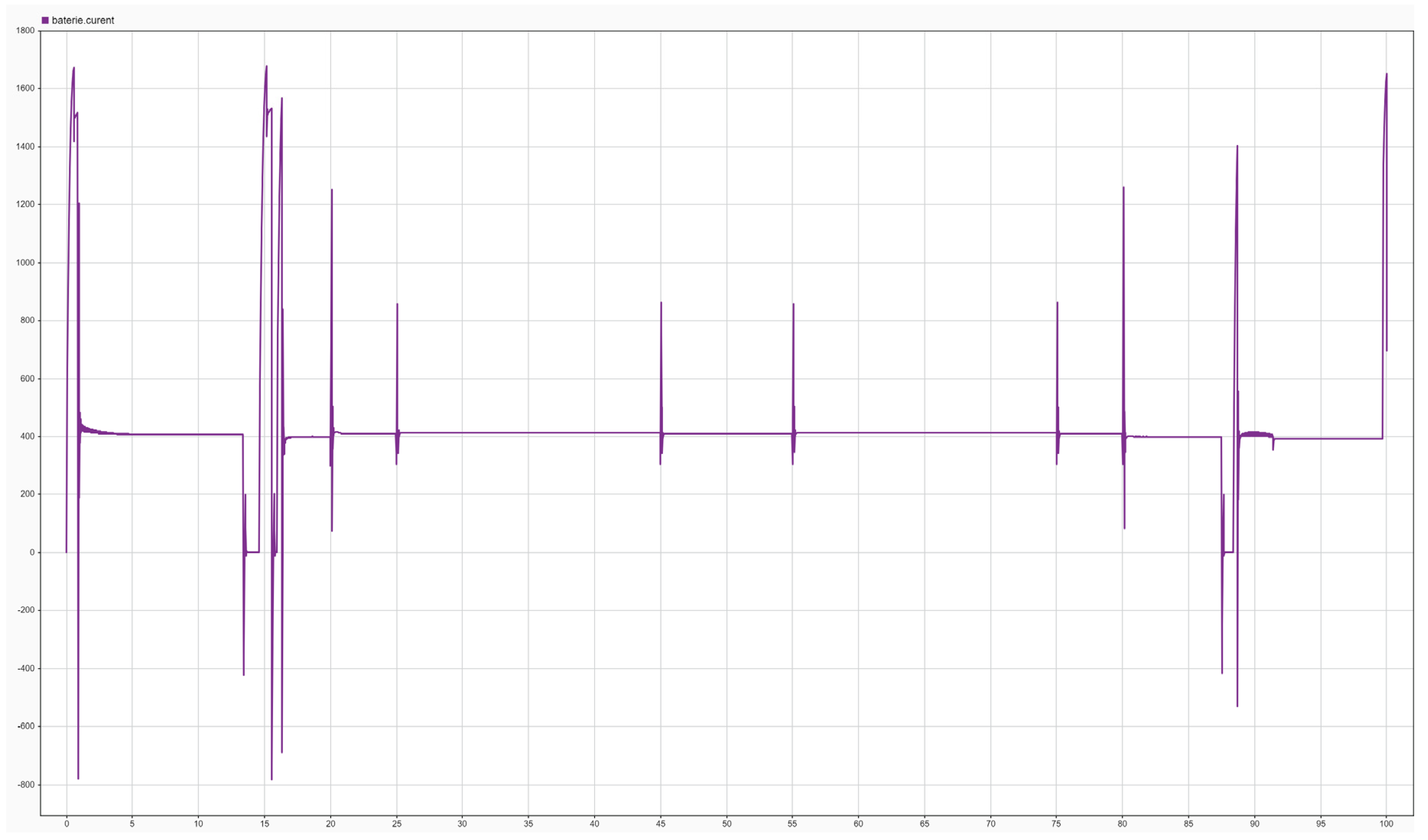
Figure 15.
Command versus response for the altitude control channel (m).
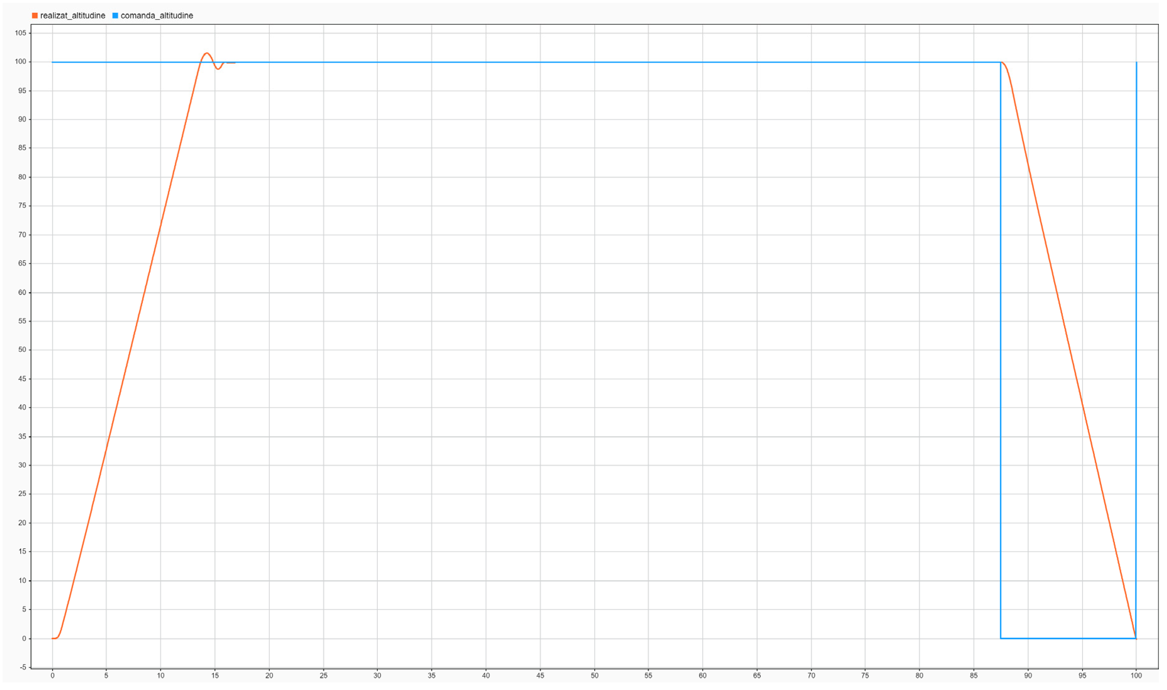
Figure 16.
Command versus response (rad) for the attitude control channels (roll, pitch, yaw).
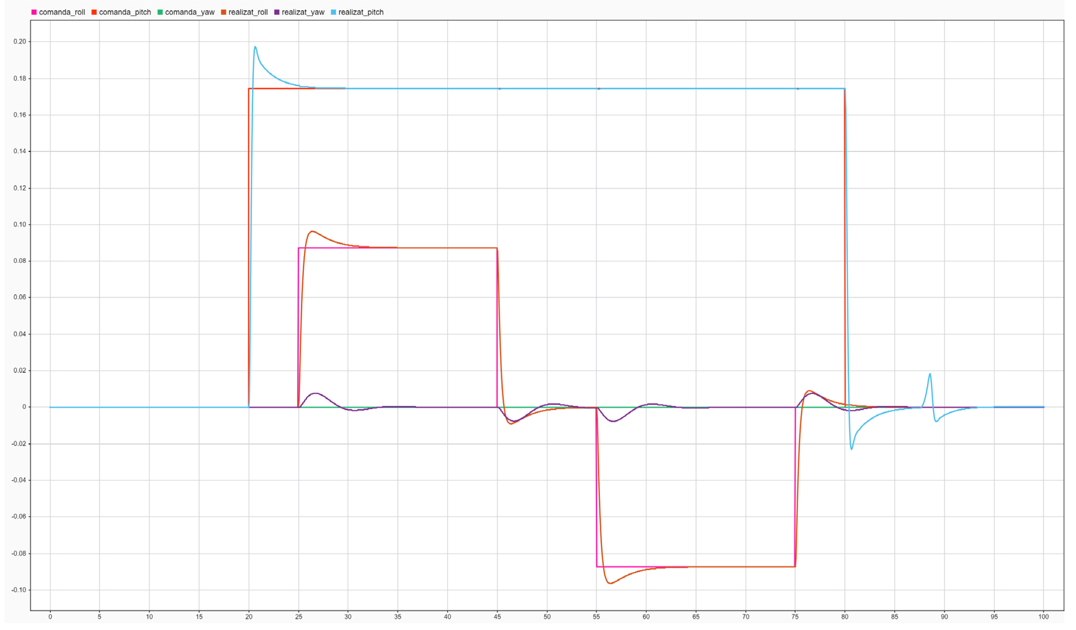
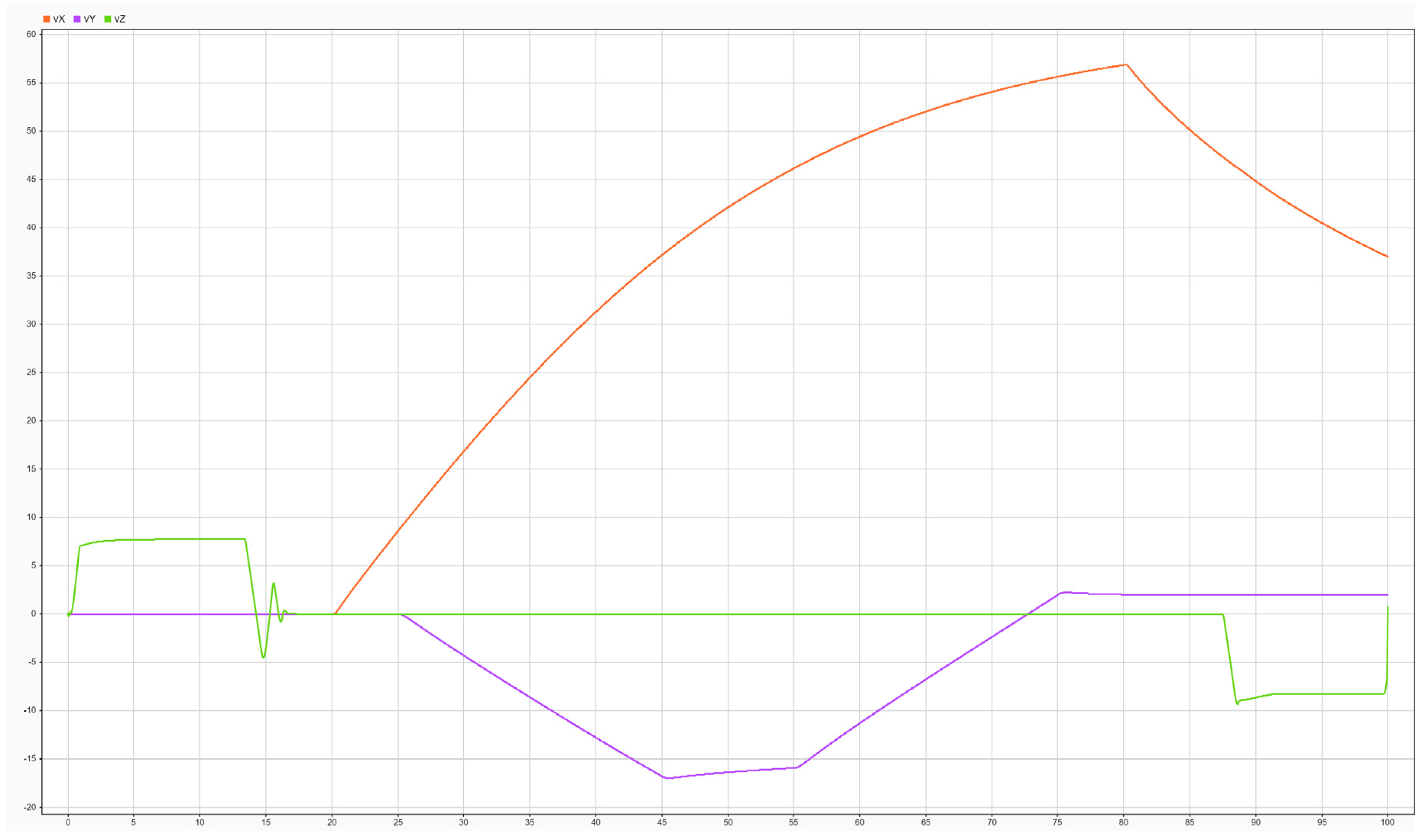
Figure 17.
Achieved linear velocities (m/s) for vX, vY si vZ.
3.2. Laboratory Testing of the VTOL System (Ground Testing)
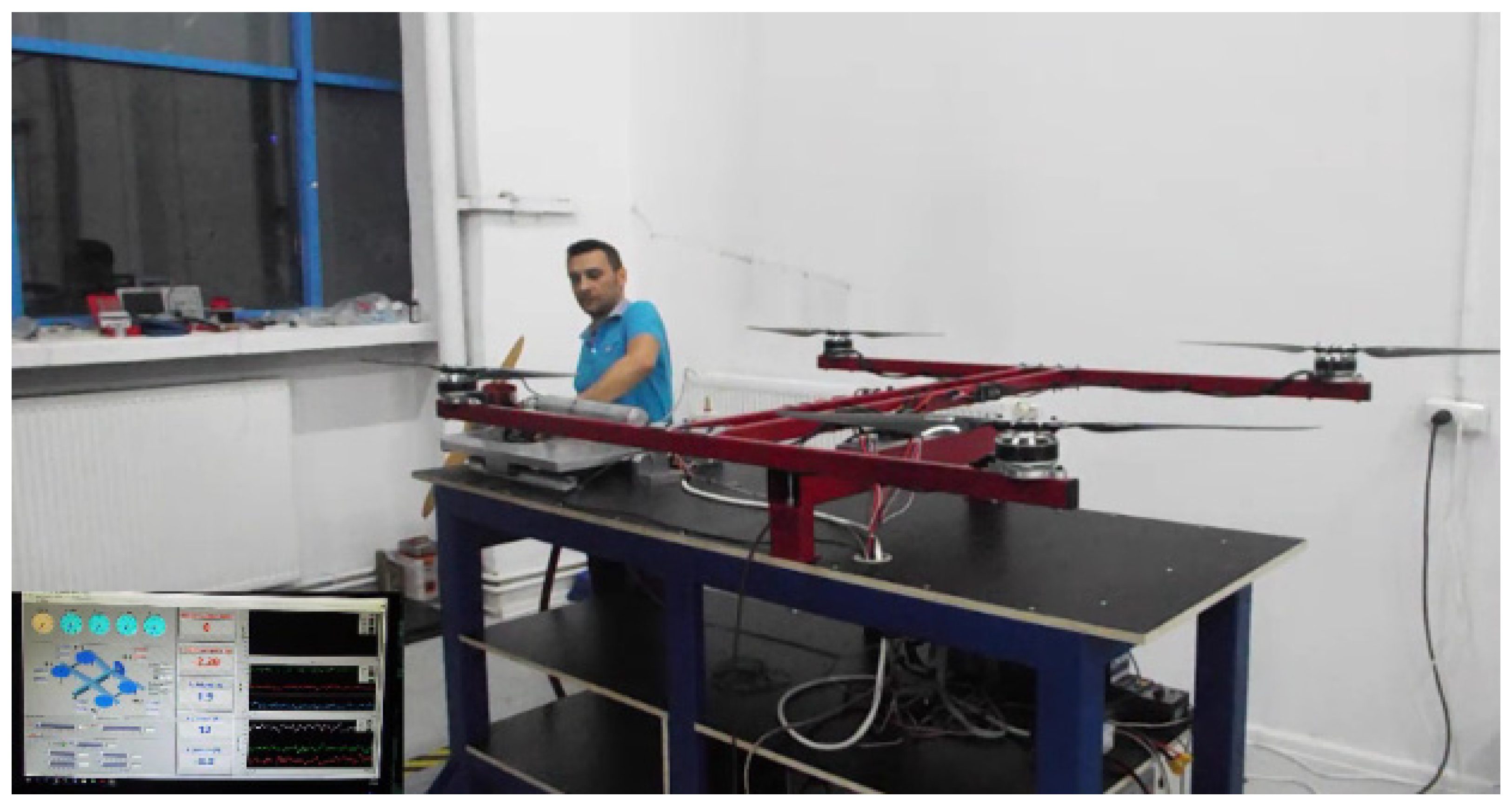
A ground-based experimental test bench available in the Mechatronics Laboratory at INCAS was employed for the preliminary validation of the proposed control architecture. The facility consists of a modular mechanical frame capable of accommodating multiple airframe configurations, including quadcopter, hexacopter, and octocopter layouts, and is mounted on a spherical joint that allows the execution of attitude-control maneuvers under constrained conditions. A six-degree-of-freedom force–moment balance is integrated between the movable frame and the fixed structure, enabling Hardware-in-the-Loop (HIL) simulations through real-time measurement and feedback of the forces and moments generated by the propulsion system. The test bench can also be equipped with an internal combustion propulsion unit representative of the fixed-wing flight mode, which serves both as an actuation element and as a source of realistic mechanical disturbances. Although the resulting vibration signatures are not quantitatively representative of the full aircraft structure, they provide valuable excitation for the assessment of the AHRS subsystem and its Kalman-based filtering performance. This setup enables safe laboratory-based tuning of the control system and supports the preparation of a stable baseline configuration prior to initial flight testing, which can subsequently be refined through dedicated in-flight optimization.
Figure 18.
Laboratory testing of the VTOL system (ground testing).
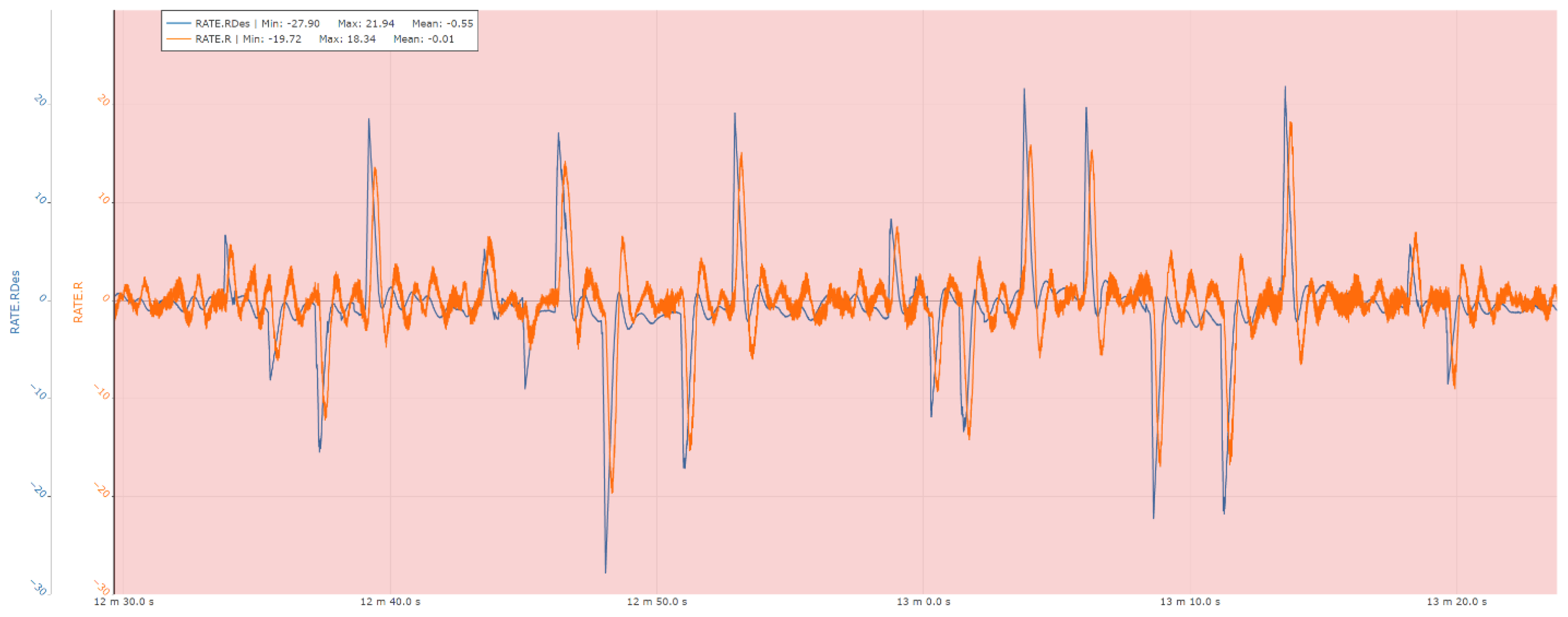
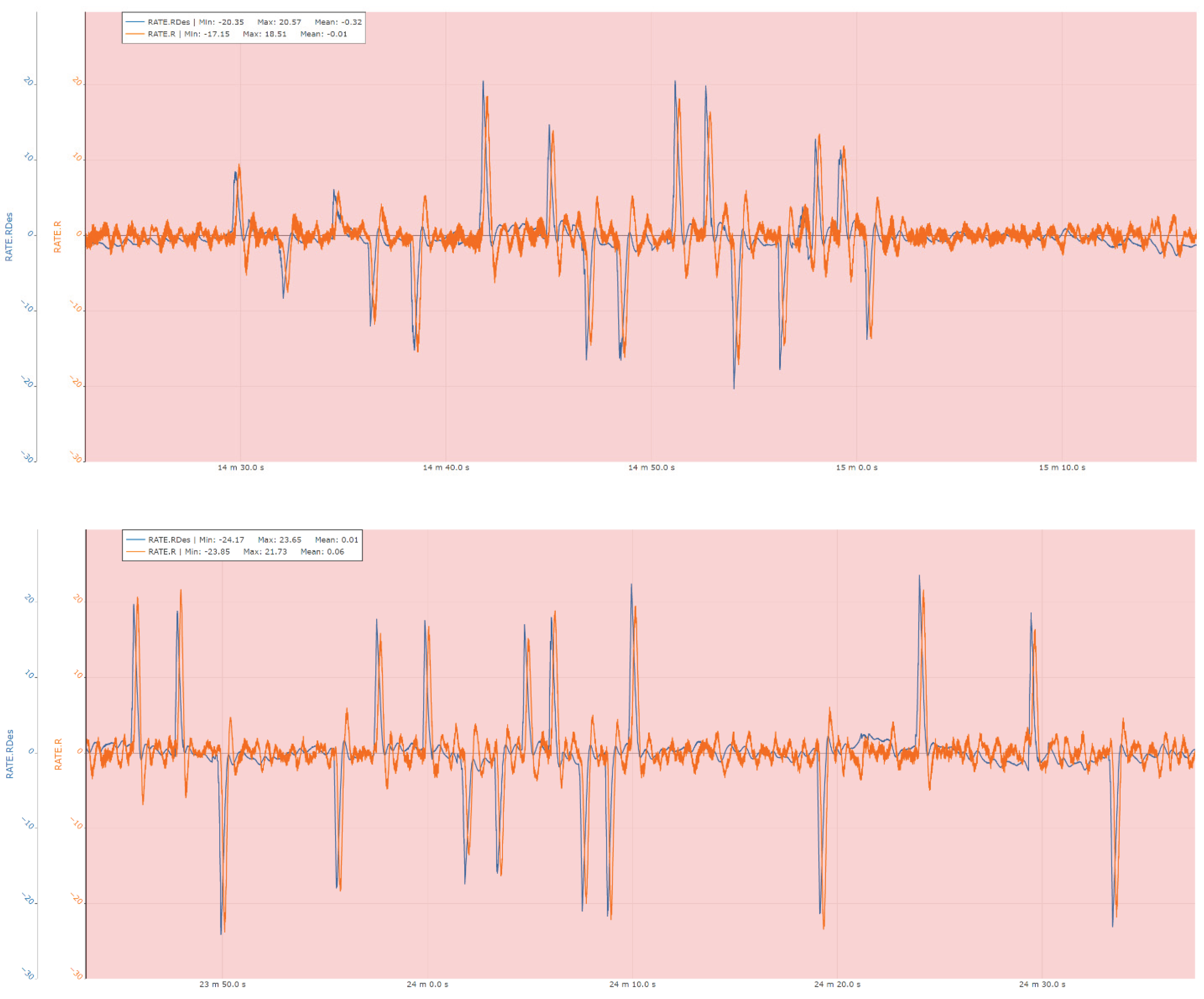
3.3. Typical Step Responses (for the VTOL Mode)
The following sections present a set of representative measurements acquired on the ground-based test bench, illustrating the performance of the attitude and heading control loops of the system. Specifically, the results include responses for roll angle and roll rate control, pitch angle and pitch rate control, as well as yaw angle and yaw rate control, providing insight into the dynamic behavior and stability characteristics of the implemented control architecture under experimental conditions.
Figure 19.
Pitch control experimental results.
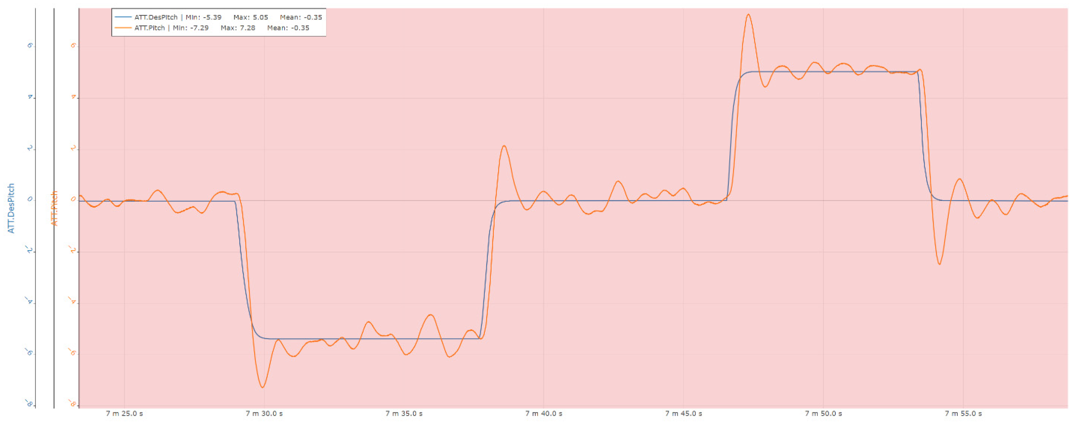
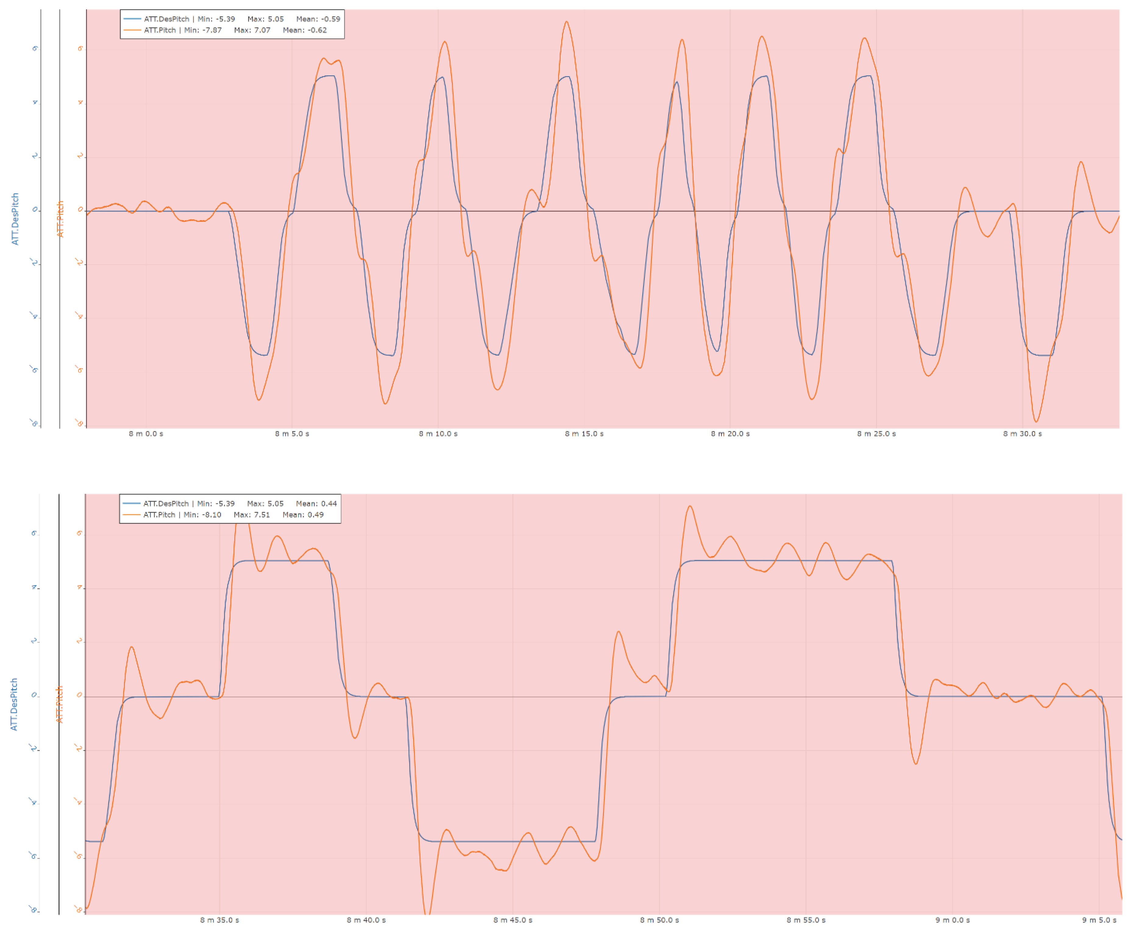
Figure 20.
Pitch rate control experimental results.
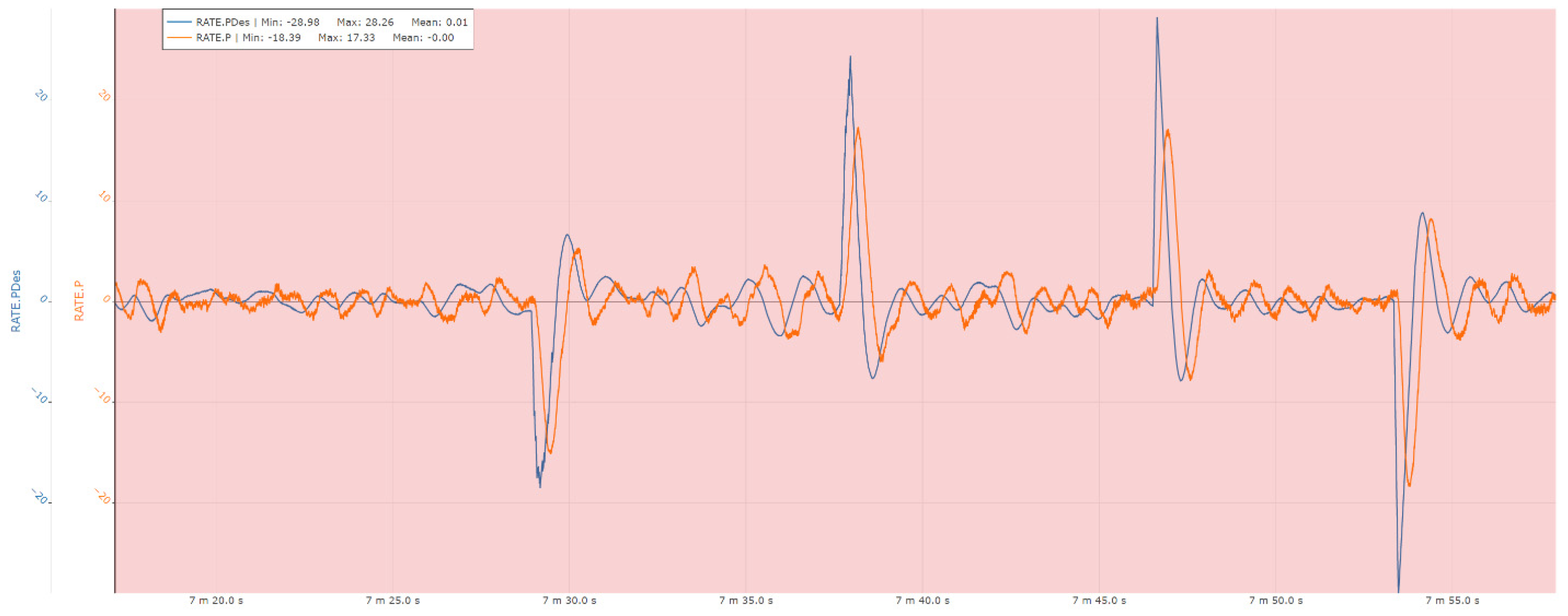
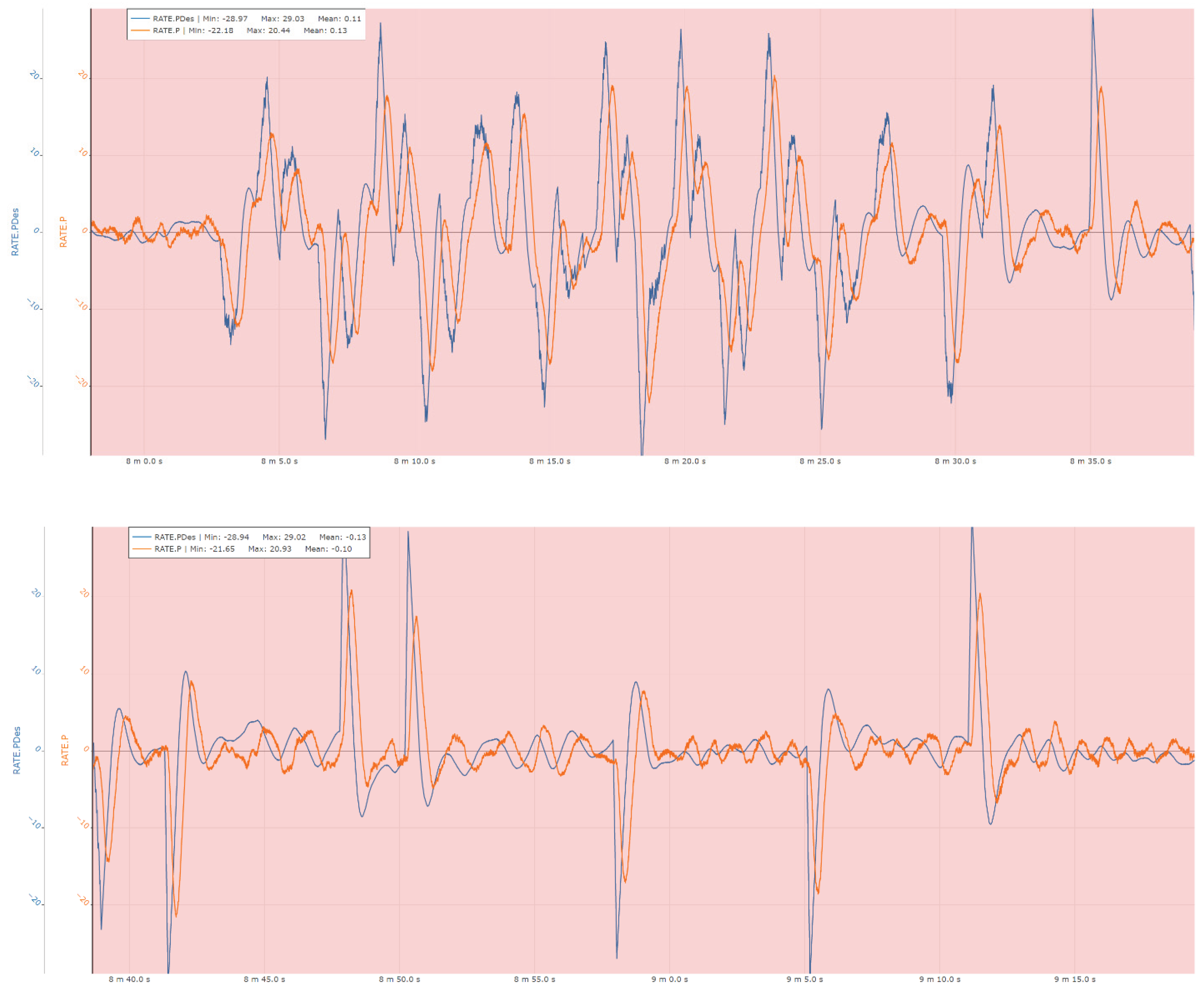
Figure 21.
Roll control experimental results.
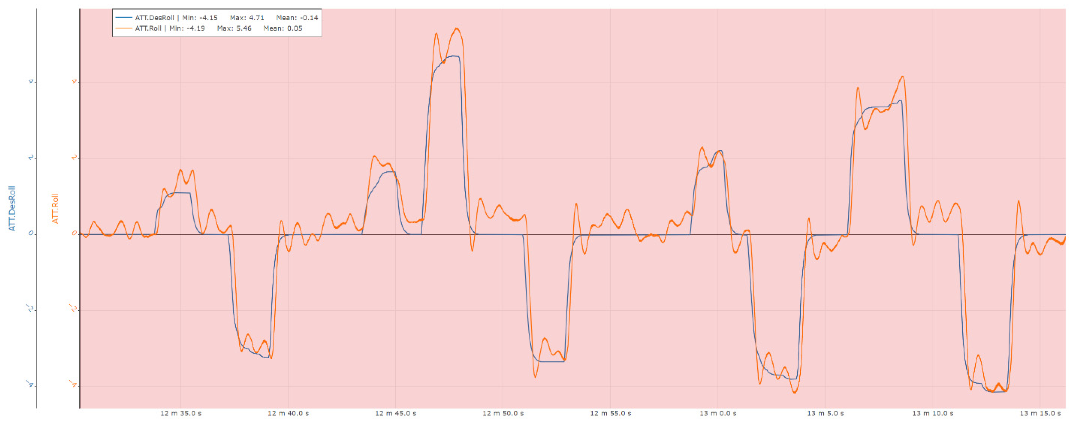
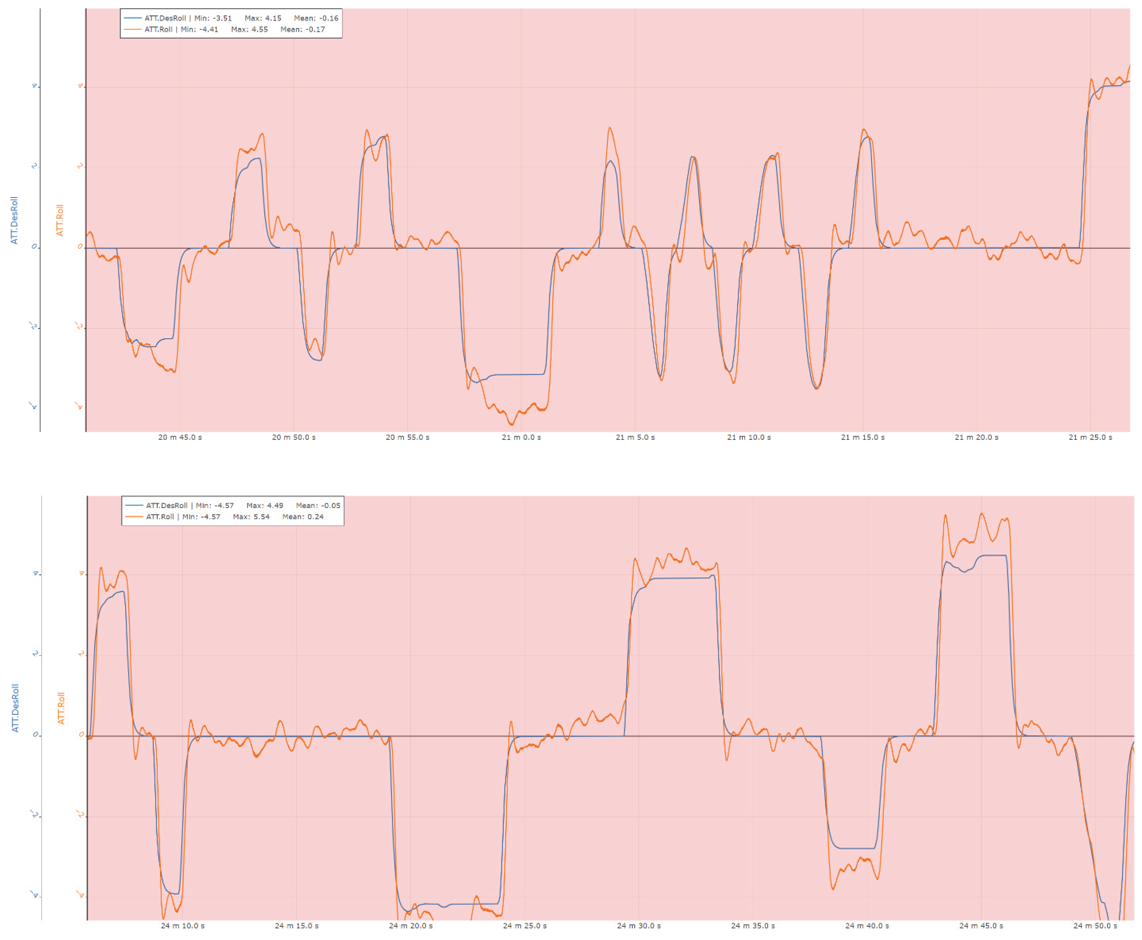
Figure 22.
Roll rate control experimental results.
4. Discussion
Following the evaluation of both the numerical simulation campaign and the ground-based experimental phase, the results indicate that the system is capable of executing the targeted flight phases and of producing physically consistent evolutions of the relevant process variables within the simulation environment. The observed system responses are coherent with the commanded maneuvers and operational conditions, including propulsion throttling, variations in electrical system loading as a function of flight regime, maneuver execution capability, and the progressive tendency toward the flight-speed limit imposed by the available propulsion power and the estimated aerodynamic characteristics of the vehicle.
During the ground-testing campaign, the control system demonstrated the capability to generate the required attitude-control corrections, with particular emphasis on the stabilization phase, which is critical for flight safety. The system maintained stable and consistent performance even under significant perturbations introduced by the internal combustion propulsion unit. In these conditions, the Attitude and Heading Reference System (AHRS) exhibited robust behavior over time, confirming the effectiveness of the filtering and estimation algorithms and their suitability for operation in vibration-rich environments.
5. Conclusion
In this work, a complete integration and validation procedure is presented for a flight control system (FCS intended to enable the conversion of an ultra-light aircraft into a vertical take-off and landing (VTOL) unmanned aerial vehicle. In the initial phase, a comprehensive mathematical model of the system was developed and implemented within an integrated simulation framework. This simulation network was conceived primarily to validate the proposed FCS architecture and incorporates both the low-level control loops and the higher-level flight management functionality, the latter being essential for progressing toward experimental flight-testing activities.
In the second phase, following the validation of a complete maneuvering sequence of the aerial vehicle in simulation, a laboratory-based Hardware-in-the-Loop (HIL) campaign was carried out. This phase employed real command signals applied to the propulsion units and real-time acquisition of AHRS data to assess the performance of the attitude-control loops under realistic perturbations, including strong vibrations generated by an internal combustion engine. The results demonstrate that the system is sufficiently mature to advance to the next development stage, namely the execution of initial flight tests required for calibration and experimental optimization of the VTOL subsystem. Compared to the idealized behavior observed during numerical simulations, the HIL experiments—conducted using a scaled physical interface and subject to significant disturbance sources—confirm the capability of the Flight Control Unit (FCU) to accurately track commanded attitude angles and angular-rate references, even when sensor measurements are heavily affected by noise arising from both electrical interference and vibration-induced disturbances impacting the AHRS subsystem.
6. Future Work
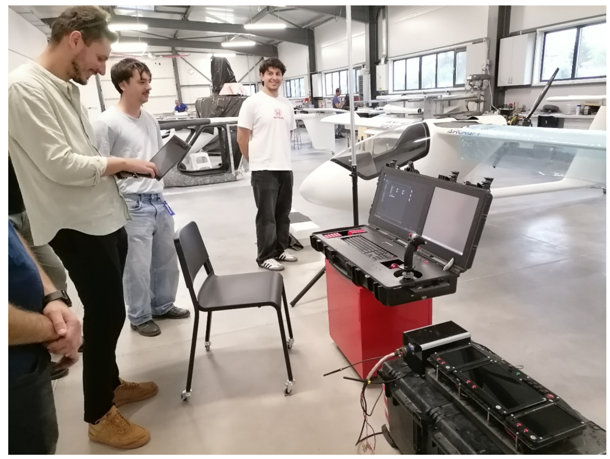
At the current stage of the project, the research team has completed the initial phases of system analysis and validation and is proceeding with the preparation of the experimental infrastructure required for the first VTOL flight tests, including the implementation of the communication architecture and the ground control station (GCS). The primary objective of these tests is to perform in-flight, low-altitude tuning and optimization of the control system, establishing a validated baseline for stability and performance. This phase is intended to serve as a prerequisite for subsequent experimental campaigns focused on the transition from VTOL operation to fixed-wing (airplane) flight, where additional aerodynamic coupling and control challenges must be addressed.
Figure 23.
Intermediate stages of preparation for the initial flight tests, focusing on the configuration and integration of the communication subsystem and the Ground Control Station (GCS) at the AVI Aircraft manufacturing and test facility.
Figure 23.
Intermediate stages of preparation for the initial flight tests, focusing on the configuration and integration of the communication subsystem and the Ground Control Station (GCS) at the AVI Aircraft manufacturing and test facility.
7. Acknowledgements
The authors acknowledge the financial support provided by the project “Romanian-Made Light Aircraft with Vertical Take-Off and Landing Capabilities”, funded by the Executive Unit for Financing Higher Education, Research, Development and Innovation (UEFISCDI) under grant agreement PN-IV-P7-7.1-PTE-2024-0248. This research was conducted within the framework of the project’s research and development activities focused on advanced autonomous flight technologies. The authors also express their sincere gratitude to all institutional partners and technical teams for their valuable contributions, technical support, and constructive discussions, which significantly facilitated the progress of this study.
References
- Beard, R.W.; McLain, T.W., Small Unmanned Aircraft: Theory and Practice Princeton University Press, 2012. [CrossRef]
- Stevens, B.L.; Lewis, F.L.; Johnson, E.N, Aircraft Control and Simulation, 3rd ed.Wiley, 2015. [CrossRef]
- Austin, R., Unmanned Aircraft Systems: UAVS Design, Development and Deployment. Wiley, 2010. [CrossRef]
- Ducard, G.J.J., Fault-Tolerant Flight Control and Guidance Systems. Springer, 2009. [CrossRef]
- Sun, Y.; Zhang, Y.; Guo, S., “Survey of Optionally Piloted Vehicles: Architectures and Challenges.”,Aerospace, 2021,8, 326. [CrossRef]
- Bartolini, G.; Fridman, L.; Levant, A.; Usai, E., Sliding Mode Control in Electro-Mechanical Systems, CRC Press, 2019. [CrossRef]
- Bouabdallah, S.; Murrieri, P.; Siegwart, R, “Design and Control of an Indoor Micro Quadrotor.”, ICRA, 2004. [CrossRef]
- Mahony, R.; Kumar, V.; Corke, P., “Multirotor Aerial Vehicles: Modeling, Estimation, and Control.”, IEEE Robotics & Automation Magazine, 2012, 19, 20–32. [CrossRef]
- Pounds, P.; Mahony, R.; Corke, P., “Modelling and Control of a Quad-Rotor Robot.” Aerospace Control Conference, 2006. [CrossRef]
- Anderson, J.D., Aircraft Performance and Design, McGraw-Hill, 1999, ISBN: 978-0070019714.
- MathWorks, Simscape Multibody User’s Guide, 2023.
- Raffo, G.V.; Ortega, M.G.; Rubio, F.R., “An Integral Predictive/Nonlinear H∞ Control Structure for a Quadrotor, Automatica, 2010, 46, 29–39. [CrossRef]
- Cook, M.V., Flight Dynamics Principles, 3rd ed, Butterworth-Heinemann, 2012. [CrossRef]
- Skogestad, S.; Postlethwaite, I., Multivariable Feedback Control, 2nd ed. Wiley, 2005. [CrossRef]
Disclaimer/Publisher’s Note: The statements, opinions and data contained in all publications are solely those of the individual author(s) and contributor(s) and not of MDPI and/or the editor(s). MDPI and/or the editor(s) disclaim responsibility for any injury to people or property resulting from any ideas, methods, instructions or products referred to in the content. |
© 2026 by the authors. Licensee MDPI, Basel, Switzerland. This article is an open access article distributed under the terms and conditions of the Creative Commons Attribution (CC BY) license (http://creativecommons.org/licenses/by/4.0/).
Copyright: This open access article is published under a Creative Commons CC BY 4.0 license, which permit the free download, distribution, and reuse, provided that the author and preprint are cited in any reuse.


