
Submitted:
05 January 2026
Posted:
05 January 2026
You are already at the latest version
Abstract
Road freight transportation remains the dominant mode for goods distribution worldwide, with articulated vehicles playing a critical role in this sector. However, these vehicles are prone to severe instability phenomena such as jackknifing, trailer sway, and rollover, particularly under high-speed or emergency maneuvers. This paper presents an advanced steering stability control strategy for articulated vehicles based on Model Predictive Control (MPC) and differential braking, aiming to enhance lateral and yaw stability during autonomous driving operations. The proposed controller integrates trajectory tracking and yaw stability objectives within a unified optimization framework, systematically handling multi-variable constraints. A dynamic model of a tractor–semitrailer combination has been developed, enabling accurate representation of vehicle kinematics and tire forces. Simulation results demonstrate that the inclusion of differential braking significantly reduces articulation angle and yaw rate deviations, preventing instability even at speeds exceeding the critical threshold of 31.04 m/s. Comparative analysis reveals that coordinated braking applied to both tractor and trailer units achieves superior performance over single-unit application, particularly under high-speed conditions. While the findings confirm the effectiveness of MPC-based differential braking for articulated vehicle stability, the study also highlights the current limitation of simulation-based validation and the need for experimental testing to ensure real-world applicability. Future research should explore multi-actuator coordination, including active front steering integration, to further enhance stability and reduce longitudinal speed loss.
Keywords:
articulated vehicles
; autonomous driving
; steering stability
; differential braking
; model predictive control
; yaw control
1. Introduction
Road freight transportation continues to dominate global logistics, accounting for a significantly higher share than maritime, rail, or air transport. Its flexibility and cost-effectiveness make it the preferred choice for domestic and regional goods distribution. Articulated vehicles—comprising a tractor unit coupled with one or more trailers—are the backbone of this system. However, their complex dynamics introduce critical safety challenges.
The stability of articulated vehicles has been a subject of extensive research for decades, driven by the critical safety challenges posed by their complex dynamics. Articulated configurations—such as tractor–semitrailers and multi-trailer combinations—are particularly vulnerable to instability phenomena including jackknifing, trailer sway (snaking), and rollover, which can occur under high-speed conditions, abrupt steering maneuvers, or uneven load distributions. These instability modes not only compromise vehicle control but also increase accident severity compared to single-unit vehicles [1,2]. Figure 1 shows an example of these instabilities.
In general, the following types of instability may occur [3].
The first type is divergent instability, which occurs when the mass of the trailer is partially supported by the towing vehicle at the coupling point. If the vertical force exerted by the trailer on the towing vehicle becomes excessively large, the vehicle combination exhibits a monotonically unstable motion, ultimately compromising overall stability.
The second type is unstable oscillatory yaw motion. In this case, the oscillation amplitude is unbounded, even under non-linear conditions. As the amplitude increases, the slip angle also grows, which reduces the average cornering stiffness due to the digressive, non-linear tire cornering force characteristic. This progressive reduction in cornering stiffness exacerbates the instability, making the situation increasingly critical.
The tractor may jackknife (Figure 2a) either under power or during braking, particularly when the rear wheels of the tractor lose grip or traction. This condition results in an acute angle between the tractor and trailer, severely compromising maneuverability and safety.
Trailer swing (Figure 2b) may occur when the trailer axle wheels lock during braking, causing the rear of the trailer to swing outward and increasing the risk of collision. Trailer swing is often considered a form of yaw instability, even though the vehicle combination may remain mathematically stable.
A complete analysis of articulated vehicles can be found in [5].
The progression from passive mechanical systems to active and intelligent controllers reflects the growing complexity of articulated vehicle dynamics and the demand for autonomous driving capabilities. Traditional systems such as Electronic Stability Control (ESC) and Roll Stability Control (RSC) provide reactive interventions but lack predictive capabilities, limiting their effectiveness under extreme conditions [1].
Another significant research challenge in the automotive industry is the development of autonomous vehicles, which are defined as vehicles capable of perceiving their surroundings and replicating human driving and control abilities [6] The degree of autonomy in a vehicle is categorized into six levels. Currently, several companies are focusing on the development of Level 4 and Level 5 vehicles [7], although the highest level available on the market today is Tesla’s Autopilot, classified as Level 3.
The growing demand for autonomous driving technologies in heavy-duty vehicles further emphasizes the need for robust stability control systems. Autonomous articulated trucks must execute complex maneuvers without human intervention, requiring advanced control strategies that can manage nonlinear dynamics, multi-body interactions, and stringent safety constraints. Traditional stability systems, such as ESC or RSC, offer partial solutions but lack the predictive capabilities and adaptability necessary for fully autonomous operation.
With respect to the control system, the MPC is an advanced control method [8]. This technique has been successfully used in many industrial applications, like thermal energy control [9], collision avoidance [10], vehicle stability [11], and energy management [12]. The MPC capacity of working with non-linear systems makes it appropriate for several applications in engineering, being of particular interest its use in autonomous vehicles [13].
Several automotive companies, such as Ford, BMW, Honda, PSA, and Toyota, are actively investigating the implementation of advanced control systems. These systems have a wide range of applications, including traction control, semi-active suspension control, vehicle stability management, and energy optimization in electric vehicles. Although such control strategies typically involve high computational demands, the integration of multi-parametric programming with an appropriately designed prediction horizon can significantly reduce the computational burden on vehicle microcontrollers, enabling real-time execution in on-board systems.
The stability of articulated vehicles under high-speed conditions and emergency maneuvers has been extensively studied, leading to the development of several advanced control strategies. These approaches differ in their mathematical foundations, robustness to uncertainties, and computational requirements. Among them, MPC has emerged as the dominant methodology. MPC predicts future system states over a receding horizon and computes optimal control actions by solving a constrained optimization problem at each time step. Its ability to handle multi-variable systems and incorporate operational constraints makes it particularly suitable for articulated vehicles with complex dynamics. Studies such as [14,15,16] demonstrate the effectiveness of MPC in trajectory tracking and yaw stability control. However, its main limitation lies in the high computational demand, which requires efficient algorithms for real-time implementation.
Another widely explored approach is Fuzzy Logic Control, including fuzzy PID variants. These controllers rely on linguistic rules and membership functions rather than precise mathematical models, making them robust to parameter variations and load changes. [17,18] highlight the intuitive design and adaptability of fuzzy controllers in managing nonlinearities. Nevertheless, their performance strongly depends on the quality of the rule base, and they may be less effective in highly dynamic scenarios compared to predictive methods.
Sliding Mode Control (SMC) represents a robust nonlinear technique that forces system trajectories to follow a predefined sliding surface, ensuring invariance to matched uncertainties. Reference [19,20] report that SMC provides excellent robustness against disturbances and parameter variations. Despite these advantages, the chattering phenomenon associated with SMC can lead to actuator wear and degraded performance, requiring careful design to mitigate this issue.
Optimal control strategies such as the Linear Quadratic Regulator (LQR) have also been applied to articulated vehicle stability. LQR minimizes a quadratic cost function to achieve optimal performance for linearized systems. Reference [21] demonstrate its effectiveness when accurate models are available. However, its applicability is limited in nonlinear and time-varying conditions, which are common in articulated vehicle dynamics.
Adaptive Control techniques offer real-time parameter adjustment to compensate for variations in system dynamics, such as changes in payload or road conditions. References [22,23] show that adaptive controllers can maintain stability under varying operating conditions. The main drawback of these methods is the increased complexity associated with tuning multiple adaptive parameters.
Finally, Integrated Multi-System Control strategies combine multiple actuators—such as active front steering and differential braking—to achieve coordinated control. References [16,24,25] emphasize that this approach provides superior performance in maintaining yaw and lateral stability, particularly in autonomous driving applications. However, it requires sophisticated coordination algorithms and sensor fusion to ensure seamless operation.
Table 1 summarizes the dominant control approaches identified in recent literature:
Several techniques are employed to prevent trailer jackknifing and trailer swing in articulated vehicle combinations.
A highly effective measure is ESC [26]. ESC systems continuously monitor vehicle dynamics and intervene by applying selective braking or reducing engine torque to maintain directional stability. These interventions are particularly valuable during sudden steering inputs or slippery road conditions, significantly reducing the likelihood of both jackknifing and trailer swing.
Anti-Lock Braking Systems (ABS) also play a critical role in stability management. ABS prevents wheel lock-up during braking (Kienhöfer and Cebon 2019)[27] , especially on trailer axles, ensuring tire-road contact and steering capability. This minimizes the risk of jackknifing and swing caused by locked wheels during abrupt deceleration.
Design improvements such as advanced fifth-wheel coupling systems [28] with controlled articulation or damping help reduce abrupt angular changes between tractor and trailer. These systems minimize jackknife risk during sharp turns or sudden deceleration.
In addition, active trailer sway control [29] detects oscillatory yaw motion and applies corrective braking or torque adjustments to stabilize the trailer. This technology is particularly useful for mitigating swing during high-speed lane changes or in crosswind conditions.
The choice of control parameters varies based on the instability mode being addressed. Studies targeting jackknifing prevention prioritize articulation angle control, while those addressing trailer sway focus on yaw rate deviation. Multi-objective controllers typically monitor both tractor and trailer yaw rates along with the articulation angle. These finding are summarized in Table 2.
Across all these techniques, differential braking emerges as a critical actuator for yaw stability. This technique involves the selective application of braking forces to individual wheels or axles, generating an asymmetric braking distribution that produces a corrective yaw moment. By counteracting undesired rotational dynamics, differential braking effectively mitigates instability phenomena such as jackknifing and trailer sway. Its implementation is cost-effective because it leverages existing braking systems, making it suitable for integration with electronic stability programs. Studies such as [1,20] confirm that tractor-only differential braking provides significant yaw control authority, although its influence on trailer dynamics is limited. Conversely, coordinated braking on both tractor and trailer units, as demonstrated by [14,15], achieves superior performance, particularly at high speeds where trailer sway becomes critical.
Several advanced control strategies have been developed to optimize the use of differential braking in articulated vehicles. Among these, MPC stands out as the dominant approach due to its predictive capabilities and systematic handling of multi-variable constraints. MPC-based controllers, such as those proposed by [14,15], integrate trajectory tracking and yaw stability objectives within a unified optimization framework. Reference [16] further extended this concept by coordinating active front steering with differential braking through a bi-level MPC structure, achieving enhanced path tracking and yaw control.
SMC has also been applied to differential braking systems, exploiting its robustness against disturbances and parameter uncertainties. Reference [19] introduced a phase-portrait-based SMC method that uses differential braking to maintain dynamic stability in car-trailer combinations. Similarly, Reference [20] implemented a multi-objective SMC algorithm for heavy tractor-semitrailers, focusing on jackknife prevention and yaw stability. Despite its robustness, SMC requires careful design to mitigate the chattering phenomenon, which can lead to actuator wear.
In addition, Fuzzy Logic Control has been employed to manage nonlinearities and uncertainties without relying on precise mathematical models. Reference [17] demonstrated that fuzzy logic can effectively generate additional yaw moments through differential braking, improving lateral stability under varying load conditions. Adaptive Control strategies have also been explored, adjusting braking torque in real time to compensate for changes in vehicle parameters such as payload or road friction. Reference [22] analyzed active trailer differential braking using adaptive control to prevent instability during dynamic maneuvers.
Recent research emphasizes Integrated Multi-System Control, which combines differential braking with other actuators such as active front steering and torque vectoring. Reference [24] proposed a coordinated control strategy for distributed-drive articulated trucks, combining differential braking with steering interventions to enhance anti-jackknifing stability. Reference [25] also investigated integrated control schemes that leverage both braking and steering for comprehensive yaw motion management.
Across all these approaches, a key finding emerges: tractor-only braking provides effective yaw control but limited trailer stabilization [1,20], while trailer-only braking directly mitigates trailer sway but lacks influence on tractor dynamics (Tian et al. 2025; Sun et al. 2016; 2014; Gao et al. 2020. Coordinated braking on both units delivers optimal stability, reducing articulation angle and yaw rate deviations under critical speed conditions [14,15,17,19]. These results confirm that differential braking, when combined with advanced control strategies, is a cornerstone for achieving safe and reliable autonomous operation of articulated vehicles. These results are summarized in Table 3.
Finally, driver assistance systems and training complement these technologies. But, in the context of autonomous driving, the role of driver assistance systems evolves into fully integrated automated control architectures that replace human intervention entirely. Traditional features such as adaptive cruise control and lane-keeping assist become foundational components of advanced autonomous systems, which incorporate real-time sensor fusion, predictive algorithms, and coordinated braking strategies to maintain stability under dynamic conditions. These systems can continuously monitor articulation angles, yaw rates, and lateral accelerations, applying corrective actions such as differential braking and active trailer sway control without relying on driver input. Furthermore, machine learning-based predictive stability controllers can anticipate critical scenarios—such as sudden lane changes or low-friction surfaces—and adjust braking forces across tractor and trailer axles to prevent jackknifing or swing.
The transition from driver assistance to full autonomy eliminates the variability associated with human decision-making and reaction times, enabling precise, coordinated interventions that optimize safety margins. However, this shift requires robust redundancy in sensing and actuation systems, as well as fail-safe algorithms to handle sensor degradation or unexpected environmental conditions. Ultimately, the integration of advanced stability control strategies—such as electronic stability control, differential braking, and active sway mitigation—into autonomous platforms is a cornerstone for achieving reliable and safe operation of articulated vehicles in mixed traffic environments.
This paper contributes to the evolving field of autonomous articulated vehicle control by introducing an MPC-based steering stability system that integrates differential braking as a primary actuator. The proposed system is designed to enable autonomous trajectory tracking while preserving yaw stability under a wide range of operating conditions, including scenarios that exceed the critical speed threshold. By leveraging predictive control, the vehicle can adapt to a predefined path and execute standard driving maneuvers without human intervention.
The core innovation lies in combining yaw stability control with coordinated regulation of vehicle speed and steering angle—parameters inherently managed by autonomous driving systems. This holistic approach ensures that articulation stability is maintained during critical situations such as sudden lane changes, emergency braking, and low-friction surfaces. Differential braking, which applies unequal braking forces to individual wheels to generate corrective yaw moments, serves as the primary mechanism for stabilizing the articulated configuration under dynamic conditions.
Ultimately, the main contribution of this work is to provide “intelligence” to articulated vehicles, transforming them into fully autonomous systems capable of safe and reliable operation. Through detailed modelling and simulation, we demonstrate the effectiveness of the proposed MPC-based control strategy and outline directions for future experimental validation.
The transition toward fully autonomous articulated vehicles requires control systems that go beyond conventional stability interventions. Existing studies employing MPC for yaw stability primarily focus on mitigating articulation angle deviations or preventing jackknifing through differential braking or steering coordination [14,15,16]. While these approaches demonstrate the predictive capability of MPC and its effectiveness in handling multi-variable constraints, they generally address stability as an isolated objective and do not explicitly regulate longitudinal speed to maintain safe operating conditions.
The system proposed in this paper introduces a holistic control strategy that integrates trajectory tracking, yaw stability, and longitudinal speed regulation within a unified MPC framework. This design enables autonomous driving functionality by allowing the articulated vehicle to follow predefined paths while dynamically adjusting its speed to prevent instability. Unlike previous works, which intervene only when instability is imminent, the proposed controller proactively manages vehicle dynamics by predicting future states and applying corrective actions in real time. Differential braking serves as the primary actuator for yaw control, while speed regulation ensures that the vehicle remains within stability limits even under high-speed or aggressive maneuvers.
This dual capability—stability preservation and speed management—represents a significant advancement over existing MPC-based solutions. By embedding longitudinal velocity control into the optimization problem, the system not only prevents instability but also optimizes overall dynamic performance, positioning it as a key enabler for safe and reliable autonomous operation of articulated vehicles. The remainder of this paper details the modeling approach, controller design, and simulation results that validate the effectiveness of this integrated strategy.
The remainder of this paper is organized as follows. Section 2 Material and Methods introduces the dynamic model of the articulated vehicle, including the assumptions and governing equations as well as the details of the design of the MPC-based control system. Section 3 presents the simulation results for different operating conditions, illustrating the effectiveness of the proposed approach. Section 4 provides a discussion of the findings in the context of previous research and highlights their implications for autonomous driving. Finally, Section 5 summarizes the main conclusions and outlines directions for future work.
2. Materials and Methods
This section describes the modeling and control framework developed for this study. It begins with the formulation of a dynamic model representing the tractor–semitrailer combination, including the assumptions, degrees of freedom, and governing equations that capture the vehicle’s kinematic and dynamic behavior. Subsequently, the design of the MPC system is presented, detailing the optimization problem, constraints, and cost function that integrate trajectory tracking, yaw stability, and longitudinal speed regulation. This section establishes the foundation for the simulation-based validation of the proposed control strategy.
2.1. Dynamic Model
The vehicle model is composed by two bodies, tractor and semitrailer, connected with an ideal revolute joint in the kingpin. The vehicle has two axles in the tractor and three axles in the semi-trailer and has been simplified by grouping the three semi-trailer axles in only one equivalent. Each axle has its equivalent left and right wheels. The truck has the driving system in the tractor rear axle, meanwhile the steering is applied in the front wheels.
With these assumptions, the vehicle model consists of a 2D model with 4 degrees of freedom, corresponding to the longitudinal and lateral displacements of the atractor, the tractor yaw angle and the semi-trailer yaw angle.
Figure 3 shows the vehicle schematics and the parameters considered in the model. The values of the parameters used in the model are relegated to Appendix A.
A global inertial reference frame and two local reference frames and are defined. The tractor is represented as the body 1 and uses subscript 1 and the semitrailer is represented with subscript 2. Figure 4 shows the model variables.
Capital letters represent variables referred to the global reference frame, small letters represent variables referred to the local reference frame, and Greek letters represent rotational variables. Bold letters are used to represent matrixes or vectors.
The notation is defined as follows:
with are the c.o.g. (center of gravity) positions referred to the inertial reference frame for each body.
with are the c.o.g. velocities referred to the local reference frame.
with are the orientation of the local reference frame with respect to the inertial reference frame.
means
means
means
means
means
with are the tractor and semitrailer yaw velocities.
means
is the vector of coordinates that represent the system movement in the inertial frame.
is the vector of the c.o.g. velocities referred to the local frames.
represents the constraint forces at the revolute joint, written in the global reference frame.
with (tractor, semitrailer) are resultant forces and momentum at the center of gravity (c.o.g.).
are the driving/braking forces in the front trailer axle, rear trailer axle and semitrailer axle.
are the stability controllers, introduced as differential braking, explained in Section 2.1 Dynamic Model.
represent the lateral tire forces in the front trailer axle, rear trailer axle and semitrailer axle.
represents the tractor steering angle
The system equations can be obtained by applying the Newton-Euler’ Laws for a multibody system with kinematic constraints. These equations are obtained in the local reference frame for both bodies and can be arranged in a matrix formulation (1):
being
and, because is in local frames (3),
Equations (1) include also the vector with two additional variables that represent the two constraint forces at the revolute joint.
The expression of the constraint equations, written in terms of velocities in the inertial frame, is as follows (4):
And considering that:
The matrix in (1) has the following expression (6):
Moreover, to know the position in global coordinates, it is necessary to add the following equations (7):
And the constraint equations written in terms of velocities in the local frame, become as (8):
Then, the equations that define the vehicle dynamics (9) are a set of six differential equations in term of accelerations (1), six differential equations in term of velocities (7), and two algebraic equations (8).
These differential-algebraic equations can be optimized and reduced to a minimum set of differential equations as a function of just the degrees of freedom of the system by eliminating the algebraic constraints, as shown in [33]
Then, two dependent velocities can be eliminated, and the equations (1) and (5) will be expressed only in terms of four independent velocities. In this case the dependent velocities chosen are the semi-trailer velocities ().
In order to do so, it is necessary to define a matrix S, that projects all the velocities to the independent ones. This matrix can be written as:
Then:
And
Finally, substituting (12) into (1) and (7), and multiplying beforehand , results in (13) and (14):
There are two types of forces and torques acting on the tractor-trailer combination.
On the one hand, are the driving/braking forces in the front trailer axle, rear trailer axle, and semitrailer axle. All of them are brake forces when the vehicle is braking, but when the truck is accelerating, only is active.
Conversely, denotes the cornering tire forces exerted by the front trailer axle, rear trailer axle, and semitrailer axle.
Finally, are the stability controllers are introduced as inputs coming from the controller in the form of torques applied the tractor and in the semi-trailer. Differential braking means that an equal and opposite increase in braking force is applied to the wheels on each side of each axle, which means that there is no additional braking increase, but there is a torque that affects the yaw movement.
The driving/braking forces are applied in the longitudinal direction of the tires, whilst the cornering tire forces are applied in the lateral direction of the tires, so the contribution to the general forces vector is shown in (15)
Lateral tire forces, , are required to negotiate a curve. They result in tire slip angles. This tire characteristic is linear for small slip angles. The gradient of the curve in the linear regime is the tire cornering stiffness, A normalized cornering stiffness is used to study the effect of scaling the tire cornering stiffness linearly with vertical load on dynamic stability. It was found in [34] that, in contrast to passenger car tires, the relation between the tire cornering stiffness and vertical load is nearly linear for truck tires and that the characteristic shows an even more linear relationship if dual tires are applied, which is often the case in truck configurations, except for the steered axle.
This means that the assumption that the cornering stiffness versus load characteristic is in its linear region is often true for truck tires.
The cornering stiffnesses are calculated as function of vertical load, with using expressions in (16) and (17)
with:
The lateral tire forces are obtained from the slip angle , that depends on the relation between the lateral and longitudinal wheel speed on the ground contact point, according to the following expressions (18) by multiplying the slip angle by the cornering stiffness :
The model assumes small steering angles, so and .
Then, the final equations result as in (19)
2.2. Design of the MPC Controller
This section presents the formulation of an optimization problem aimed at designing controllers that guide the vehicle and maintain yaw stability. The optimal control design is derived from the dynamic model of the trailer. The control inputs considered include the driving and braking forces at each axle, the steering angle, and the torque associated with differential braking for yaw stability control. Operational constraints are imposed by defining permissible limits for both inputs and outputs. Additionally, an objective function is introduced to capture the goals of the control problem: tracking a desired trajectory while ensuring yaw stability.
2.2.1. Optimal Control Design
Regrouping the previous expression (19) the system equations for the vehicle dynamics are written in a compacted way as (20):
where:
is a vector including the states.
is vector with the independent velocities.
includes the global positions and orientations for tractor and semitrailer.
is a vector including the inputs.
An MPC approach is proposed for the vehicle. MPC is selected due to its capability of systematically handling multiple input and state constraints, which in this problem are critical. According to the receding horizon principle, at each time step the MPC algorithm computes the optimal control and state trajectories solving a finite horizon optimization problem.
For the formulation of the MPC a prediction horizon is considered at time t. The notation represents the state vector at time , predicted at time , obtained by starting from the current state , and where denotes the unknown input variables to be optimized. As previously stated, the subscript 1 denotes the tractor and subscript 2 denotes the semitrailer.
2.2.2. System Dynamics
Equations (21) represents the system dynamics updates for the discrete-time model obtained from (20). The initial state is set in (22)
2.2.3. Constraints
The controlled inputs include the driving and braking forces at each axle, the steering angle, and the torque representing differential braking for yaw stability control.
The driving and braking forces must be bounded by:
The driving / braking forces constraints include the limitation of the maximum driving and braking force and the power limitation in driving and braking. (23) to (26) represent the maximum driving/braking forces and the maximum power for driving/braking. Equation (23) and (25) are bounded between because axles 1 and 3 only break, instead of axel 2 (24), bounded between because in this axle, we have de traction.
Constraints (27) and (28) bounds the steering angle and the steering rate.
And constraints (29) constraints the differential braking stability controllers
In the MPC formulation, we will refer to all these constraints as .
In order to guarantee that the vehicle respects the speed limit, the speed is bounded by the following constraint (30):
In the MPC, we will refer to this constraint as .
2.2.4. Cost Function
The objective of the truck is to circulate at the speed fixed by a reference, following a trajectory previously define, and preserving yaw stability. The objective control may be stablished with an objective function composed by different terms. This objective function is used to minimize the different errors produced in the trajectory tracking and in the relative yaw rate, as shown in Figure 5.
Therefore, the objective function (31) is defined as follows:
with
The different terms in the cost function (31) to (34) have the following meaning: represents the weight penalizing the output deviation from the truck maximum desired speed, being the maximum desired speed. represents the weight penalizing the lateral displacement in the trajectory tracking, being the Y coordinate of the desired trajectory. represents the weight penalizing the orientation in the trajectory tracking being the orientation of the desired trajectory.
The term (34) is the key point in the yaw stability control. This term minimizes the yaw rate between tractor and semitrailer, so it preserves the yaw instability.
2.2.5. Model Predictive Control Formulation
As previously said, the objective of the truck is to circulate at the speed fixed by a reference, following a trajectory previously define, and preserving yaw stability.
Therefore, the optimization problem is formulated as (35) – (39):
subject to:
The resulting optimal states and inputs of (35) – (39) are denoted as following:
For closing the loop, the first input is applied to the system (20) during the time interval
At the next time step t+1, a new optimal problem in the form of (35) – (39) is solved over a shifted horizon, based on a new states’ measurement.
3. Results
Two different models have been developed for the design and validation of the yaw stability controller through simulation. The first model represents a trailer without a yaw stability controller, whereas the second model incorporates the stability controller. In the first model, term (34) of the cost function is not considered, while in the second model this term is introduced.
A velocity profile was defined following a sinusoidal path, as expressed in equation (42):
For the trailer parameters included in Appendix A, and following the expression obtained by [5], the critical speed was calculated as 31.04 m/s. Stability control was then evaluated in two cases. The first case considered a reference speed of 15 m/s, which is below the critical speed. Under these conditions, the trailer remains stable without the stability controller, as shown in Figure 6, Figure 7 and Figure 8.
Figure 6 illustrates the trailer behavior without the stability controller, showing that the trailer remains stable and accurately tracks the desired trajectory. Figure 7 presents the trailer behavior with the stability controller activated. A comparison of these two figures indicates that, although the vehicle remains stable without the controller, the relative yaw angle between the tractor and semitrailer is slightly higher than in the case with the controller.
Figure 8 illustrates the tracking errors. The lateral position and yaw errors are sufficiently small, indicating that the truck accurately follows the desired trajectory. Additionally, the yaw rate error remains within acceptable limits, confirming that the trailer maintains stability in both configurations—without and with the yaw stability controller.
The second simulation case considers a reference speed of 35 m/s, which exceeds the critical speed. Under these conditions, the trailer becomes unstable without the stability controller, as shown in Figure 9, Figure 10 and Figure 11. Figure 9 illustrates that the trailer fails to track the desired trajectory, exhibiting oscillatory behavior before reducing its speed in an attempt to reach a stable velocity. Figure 10 presents the trailer behavior with the stability controller activated, demonstrating that the trailer remains stable throughout the maneuver.
Figure 11 displays the tracking errors for both configurations. The data clearly highlight the unstable behavior of the trailer without stability control compared to the controlled case, where the trajectory and yaw dynamics remain within acceptable limits.
4. Discussion
The findings of this study provide significant insights into the dynamic behavior of articulated vehicles under autonomous control and the effectiveness of the proposed MPC-based strategy. The controller’s ability to integrate trajectory tracking, yaw stability, and longitudinal speed regulation within a single optimization framework represents a major advancement over conventional stability systems. Traditional approaches, such as ESC or RSC, typically intervene reactively when instability is detected. In contrast, the proposed system operates proactively, predicting future states and applying corrective actions before instability occurs.
The first simulation scenario, at a reference speed below the critical threshold, demonstrates that the vehicle remains stable even without the yaw stability controller. However, the inclusion of the controller improves articulation behavior by reducing the relative yaw angle between the tractor and semitrailer. This reduction minimizes structural stress at the coupling point and enhances overall maneuverability, which is particularly relevant for autonomous vehicles operating in confined spaces or performing lane changes. Although the improvement is less pronounced under inherently stable conditions, it confirms the controller’s capacity to optimize performance beyond basic stability requirements.
The second scenario, at a reference speed exceeding the critical threshold, underscores the importance of active stability control for high-speed autonomous operation. Without the controller, the trailer exhibits oscillatory yaw motion, fails to track the desired trajectory, and ultimately reduces its speed in an attempt to regain stability. This behavior illustrates the inherent limitations of passive dynamics and the risks associated with operating near or above critical speed. Conversely, the MPC-based system maintains stability throughout the maneuver by applying differential braking and dynamically adjusting longitudinal velocity. This dual capability—stabilizing yaw motion and regulating speed—ensures that the vehicle remains within safe operating limits while preserving trajectory accuracy.
The integration of speed regulation into the stability control strategy is a key innovation. By actively managing longitudinal velocity, the controller prevents the onset of instability rather than merely reacting to it. This proactive approach is essential for autonomous articulated vehicles, which must execute complex maneuvers without human intervention. Furthermore, the ability to coordinate braking torques across tractor and trailer units enhances yaw control authority and reduces articulation angle deviations, contributing to improved safety margins under extreme conditions. These results align with previous studies emphasizing the benefits of multi-actuator coordination but extend the concept by embedding speed regulation as a core stability mechanism.
Overall, the discussion highlights that the proposed MPC-based system is not limited to preventing instability; it also optimizes vehicle dynamics for autonomous operation. By combining predictive control with differential braking and speed management, the system addresses the fundamental challenges of articulated vehicle stability in a holistic manner. This capability positions the approach as a cornerstone for future autonomous heavy-duty transportation systems.
5. Conclusions
This paper introduces an advanced control strategy for autonomous articulated vehicles that combines yaw stability control with longitudinal speed regulation. The proposed MPC-based system enables the vehicle to follow predefined trajectories while maintaining stability under a wide range of operating conditions, including scenarios that exceed the critical speed threshold. Unlike conventional systems, which intervene only during critical events, the developed controller proactively manages vehicle dynamics by predicting future states and applying corrective actions in real time.
The simulation results confirm that the controller effectively mitigates instability phenomena such as jackknifing and trailer sway. At moderate speeds, the system improves articulation behavior by reducing the relative yaw angle between the tractor and semitrailer, enhancing maneuverability and safety margins. At high speeds, where instability is most likely to occur, the controller demonstrates its full potential by maintaining trajectory tracking and yaw stability while dynamically adjusting longitudinal velocity to remain within safe limits. This dual functionality—stability preservation and speed regulation—represents a significant advancement for autonomous driving applications.
The main contribution of this work lies in its holistic approach to articulated vehicle control. By integrating trajectory tracking, yaw stability, and speed regulation within a unified optimization framework, the system ensures safe and reliable operation without compromising maneuverability. These findings establish a foundation for future research aimed at experimental validation and real-world implementation. Future work should focus on developing scaled prototypes or instrumented vehicles to confirm the simulation results under practical conditions. Additionally, further enhancements could include multi-actuator coordination strategies, such as combining differential braking with active front steering and torque vectoring, to improve performance during aggressive maneuvers and reduce longitudinal speed loss.
In summary, the proposed MPC-based control system provides a robust and intelligent solution for autonomous articulated vehicles, addressing critical safety challenges while enabling efficient and reliable operation. Its ability to prevent instability, optimize articulation dynamics, and regulate speed positions it as a key technology for the next generation of autonomous heavy-duty transportation systems.
Supplementary Materials
The following supporting information can be downloaded at: https://www.mdpi.com/article/doi/s1, Video 1a: title; Video 1b: title.
Author Contributions
Conceptualization, J.F; methodology, J.F.; software, J.F.; validation, J.F.; formal analysis, J.F.; investigation, J.F.; writing—original draft preparation, J.F.; writing—review and editing, J.F.; visualization, J.F.; All authors have read and agreed to the published version of the manuscript.
Funding
“This research received no external funding”.
Data Availability Statement
Data are contained within the article.
Conflicts of Interest
The author declares that the research was conducted in the absence of any commercial or financial relationships that could be construed as a potential conflict of interest.
Abbreviations
The following abbreviations are used in this manuscript:
| ABS | Anti-Lock Braking Systems |
| ESC | Electronic Stability Control |
| LQR | Linear Quadratic Regulator |
| MPC | Model Predictive Control |
| RSC | Roll Stability Control |
| SMC | Sliding Mode Control |
Appendix A
| Parameter | Description | Value |
| Tractor mass | 7449 Kg | |
| Radius of gyration | 1.89 m | |
| Semi-trailer mass | 32551 Kg | |
| Radius of gyration | 4,05 m | |
| Dist. tractor front - c.o.g. | 1.10 m | |
| Dist. tractor rear axle - c.o.g. | 2.49 m | |
| Dist. semitrailer axle - c.o.g. | 3.15 m | |
| Dist. kingpin semitrailer - c.o.g. | 4.98 m | |
| Dist. kingpin tractor dist. - c.o.g. | 1.81 m | |
| Normalized cornering stiffness | 5.73 1/rad | |
| Power (drive) | 500 kW | |
| Power (brake) | 700 V | |
| Max. steering angle | 10º | |
| Max. steering rate | 0,17 rad/s |
References
- Hac, D. Fulk; Chen, H. ‘Stability and Control Considerations of Vehicle-Trailer Combination’. SAE Int. J. Passeng. Cars - Mech. Syst. 2008, vol. 01(no. 1), 925–937. [Google Scholar] [CrossRef]
- Emheisen, M. A.; Emirler, M. T.; Ozkan, B. ‘Lateral Stability Control of Articulated Heavy Vehicles Based on Active Steering System’. Int. J. Mech. Eng. Robot. Res. 2022, 575–582. [Google Scholar] [CrossRef]
- Troger, H.; Zeman, K. ‘A Nonlinear Analysis of the Generic Types of Loss of Stability of the Steady State Motion of a Tractor-Semitrailer∗’. Veh. Syst. Dyn. 1984, vol. 13(no. 4), 161–172. [Google Scholar] [CrossRef]
- Ellis, J. R. Vehicle Handling Dynamics; Professional Engineering Publishing, 1994. [Google Scholar]
- Van De Molengraft-Luijten, M. F. J.; Besselink, I. J. M.; Verschuren, R. M. A. F.; Nijmeijer, H. ‘Analysis of the lateral dynamic behaviour of articulated commercial vehicles’. Veh. Syst. Dyn. 2012, vol. 50(no. sup1), 169–189. [Google Scholar] [CrossRef]
- Anderson, J.; Kalra, N.; Stanley, K.; Sorensen, P.; Samaras, C.; Oluwatola, O. Autonomous Vehicle Technology: A Guide for Policymakers; RAND Corporation, 2016. [Google Scholar] [CrossRef]
- Litman, T. ‘Autonomous vehicle implementation predictions’. Victoria Transport Policy Institute, 17/11/20025. 202. Available online: https://www.vtpi.org/avip.pdf (accessed on 17 December 2025).
- Qin, S. J.; Badgwell, T. A. ‘A survey of industrial model predictive control technology’. Control Eng. Pract. 2003, vol. 11(no. 7), 733–764. [Google Scholar] [CrossRef]
- Mantovani, G.; Ferrarini, L. ‘Temperature Control of a Commercial Building With Model Predictive Control Techniques’. IEEE Trans. Ind. Electron. 2015, vol. 62(no. 4), 2651–2660. [Google Scholar] [CrossRef]
- Wang, J.-Q.; Li, S. E.; Zheng, Y.; Lu, X.-Y. ‘Longitudinal collision mitigation via coordinated braking of multiple vehicles using model predictive control’. Integr. Comput.-Aided Eng. 2015, vol. 22(no. 2), 171–185. [Google Scholar] [CrossRef]
- Di Cairano, S.; Tseng, H. E.; Bernardini, D.; Bemporad, A. ‘Vehicle Yaw Stability Control by Coordinated Active Front Steering and Differential Braking in the Tire Sideslip Angles Domain’. IEEE Trans. Control Syst. Technol. 2013, vol. 21(no. 4), 1236–1248. [Google Scholar] [CrossRef]
- Zhu, Bing; Tazvinga, H.; Xia, Xiaohua. ‘Switched Model Predictive Control for Energy Dispatching of a Photovoltaic-Diesel-Battery Hybrid Power System’. IEEE Trans. Control Syst. Technol. 2015, vol. 23(no. 3), 1229–1236. [Google Scholar] [CrossRef]
- Hrovat, D.; Di Cairano, S.; Tseng, H. E.; Kolmanovsky, I. V. ‘The development of Model Predictive Control in automotive industry: A survey’. 2012 IEEE International Conference on Control Applications, Dubrovnik, Croatia, Oct. 2012; IEEE; pp. 295–302. [Google Scholar] [CrossRef]
- Abroshan, M.; Hajiloo, R.; Hashemi, E.; Khajepour, A. ‘Model predictive-based tractor-trailer stabilisation using differential braking with experimental verification’. Veh. Syst. Dyn. 2021, vol. 59(no. 8), 1190–1213. [Google Scholar] [CrossRef]
- Wang, W.; Li, G.; Liu, S. ‘Research on Trajectory Tracking Control of a Semi-Trailer Train Based on Differential Braking’. World Electr. Veh. J. 2024, vol. 15(no. 1), 30. [Google Scholar] [CrossRef]
- Yu, H.; Li, E.; Corno, M.; Savaresi, S. M. ‘Bi-level path tracking control of tractor semi-trailers by coordinated active front steering and differential braking’. Proc. Inst. Mech. Eng. Part J. Automob. Eng. 2025, vol. 239(no. 8), 3667–3681. [Google Scholar] [CrossRef]
- Bai, Z.; Lu, Y.; Li, Y. ‘Method of Improving Lateral Stability by Using Additional Yaw Moment of Semi-Trailer’. Energies 2020, vol. 13(no. 23), 6317. [Google Scholar] [CrossRef]
- Zhou, Q.; Zhang, H.; He, Y.; Su, Y.; Jiang, Y.; Zheng, S. ‘A directional-performance control design for articulated heavy vehicles with extendable-trailers’. Veh. Syst. Dyn. 2025, vol. 63(no. 12), 2393–2438. [Google Scholar] [CrossRef]
- Zhang, N. ‘A Phase Portrait-Based Sliding Mode Control Method to Improve Dynamic Stability of Car-Trailer Combinations via Differential Braking’. IEEE Trans. Intell. Transp. Syst. 2025, vol. 26(no. 11), 19457–19467. [Google Scholar] [CrossRef]
- Zong; Zhu, T.; Wang, C.; Liu, H. ‘Multi-objective stability control algorithm of heavy tractor semi-trailer based on differential braking’. Chin. J. Mech. Eng. 2012, vol. 25(no. 1), 88–97. [Google Scholar] [CrossRef]
- Tianjun, Z.; Changfu, Z. ‘Modelling and Active Safe Control of Heavy Tractor Semi-Trailer’. 2009 Second International Conference on Intelligent Computation Technology and Automation, Changsha, Hunan, China, 2009; IEEE; pp. 112–115. [Google Scholar] [CrossRef]
- Sun, T.; He, Y.; Ren, J. ‘Dynamics Analysis of Car-Trailer Systems with Active Trailer Differential Braking Strategies’. SAE Int. J. Passeng. Cars - Mech. Syst. 2014, vol. 07(no. 1), 73–85. [Google Scholar] [CrossRef]
- Chen, L.-K.; Shieh, Y.-A. ‘Jackknife Prevention for Articulated Vehicles Using Model Reference Adaptive Control’. Proc. Inst. Mech. Eng. Part J. Automob. Eng. 2011, vol. 225(no. 1), 28–42. [Google Scholar] [CrossRef]
- Tian, Y.; Ma, H.; Zhang, Y.; Wen, G.; Wang, X.; Li, L. ‘Synergistic Control Strategy for Enhanced Anti-Jackknifing Stability in Distributed-Drive Articulated Trucks’. IEEE Trans. Transp. Electrification 2025, vol. 11(no. 5), 12289–12299. [Google Scholar] [CrossRef]
- Zhao, Y.; Chen, S.; Shim, T. ‘Investigation of Trailer Yaw Motion Control Using Active Front Steer and Differential Brake’. SAE Int. J. Mater. Manuf. 2011, vol. 04(no. 1), 1057–1067. [Google Scholar] [CrossRef]
- Erdinc, U.; Jonasson, M.; Kati, M. S.; Laine, L.; Jacobson, B.; Fredriksson, J. ‘Yaw Stability Control of Vehicles Using a Slip Polytope Validated with Real Tests’. In 16th International Symposium on Advanced Vehicle Control; Mastinu, G., Braghin, F., Cheli, F., Corno, M., Savaresi, S. M., Eds.; Lecture Notes in Mechanical Engineering; Springer Nature Switzerland: Cham, 2024; pp. 130–136. [Google Scholar] [CrossRef]
- Kienhöfer, F. W.; Cebon, D. ‘An investigation of ABS stratetigies for artivulated vehicles’. Proceedings 8 th International Symposium on Heavy Vehicle Weights and Dimensions 14 th - 18 th March, Johannesburg, South Africa ëLoads, Roads and the Information Highwayí, Johannesburg, South Africa, 2019. [Google Scholar]
- Skotnikov, G. I.; Jileykin, M. M.; Komissarov, A. I. ‘Increasing the stability of the articulated lorry at braking by locking the fifth wheel coupling’. IOP Conf. Ser. Mater. Sci. Eng. 2018, vol. 315, 012027. [Google Scholar] [CrossRef]
- Zhu, S.; He, Y. ‘A Coordinated Control Scheme for Active Safety Systems of Multi-trailer Articulated Heavy Vehicles’. In Advances in Dynamics of Vehicles on Roads and Tracks III; Huang, W., Ahmadian, M., Eds.; Lecture Notes in Mechanical Engineering; Springer Nature Switzerland: Cham, 2024; pp. 824–834. [Google Scholar] [CrossRef]
- Parra, A.; Tavernini, D.; Gruber, P.; Sorniotti, A.; Zubizarreta, A.; Pérez, J. ‘On pre-emptive vehicle stability control’. Veh. Syst. Dyn. 2022, vol. 60(no. 6), 2098–2123. [Google Scholar] [CrossRef]
- Sun, T.; Lee, E.; He, Y. ‘Non-Linear Bifurcation Stability Analysis for Articulated Vehicles with Active Trailer Differential Braking Systems’. SAE Int. J. Mater. Manuf. 2016, vol. 09(no. 3), 688–698. [Google Scholar] [CrossRef]
- Gao, Z.; Li, D.; Xie, L. ‘Study on the Differential Braking of an Eddy Current Retarder Axle Used for Articulated Vehicles’. 2020 IEEE 5th International Conference on Intelligent Transportation Engineering (ICITE), Beijing, China, Sept. 2020; IEEE; pp. 596–600. [Google Scholar] [CrossRef]
- Felez, J.; Romero, G.; Maroto, J.; Martinez, M. L. ‘Simulation of Multi-body Systems Using Multi-bond Graphs’. In Bond Graph Modelling of Engineering Systems; Borutzky, W., Ed.; Springer New York: New York, NY, 2011; pp. 323–354. [Google Scholar] [CrossRef]
- H. B. Pacejka, Tire and vehicle dynamics. Elsevier, 2006.
Figure 1.
The snaking phenomenon that can occur with any car/trailer combination.
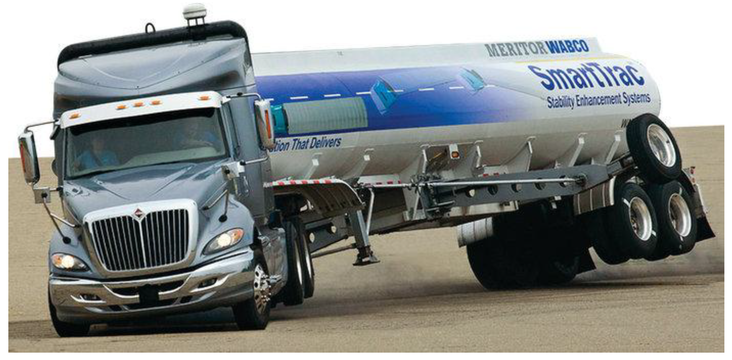
Figure 2.
Two jack-knife possibilities of a tractor-semitrailer.
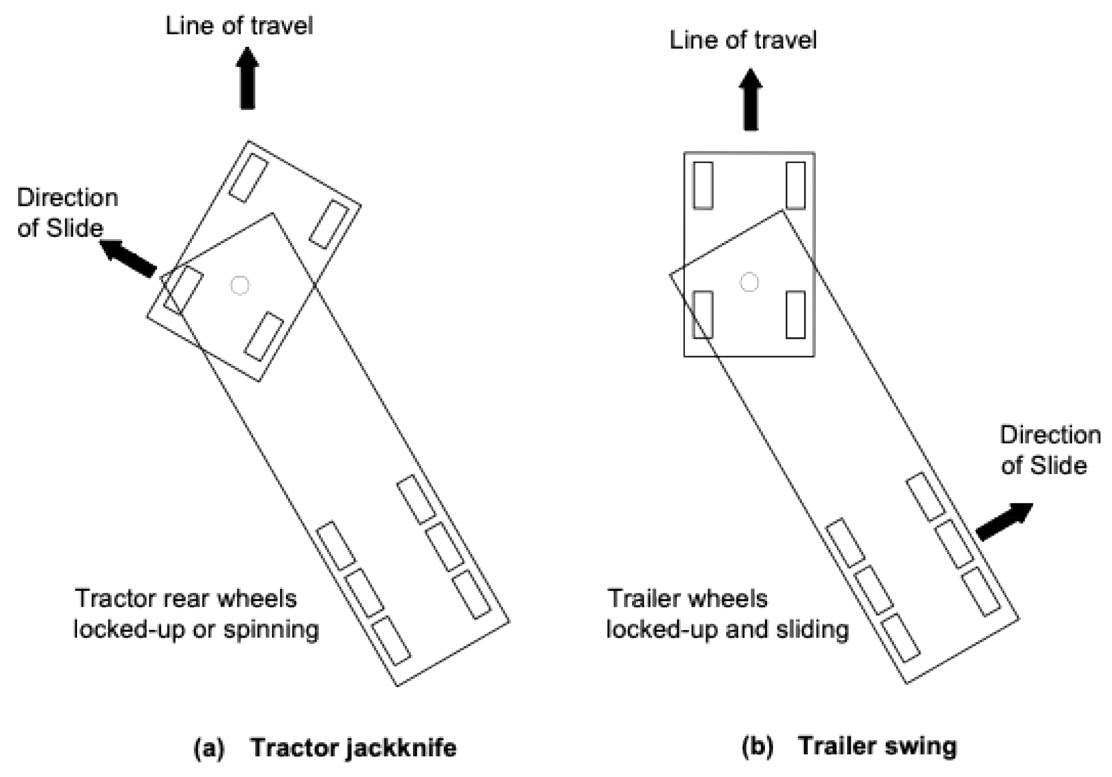
Figure 3.
Model vehicle parameters.
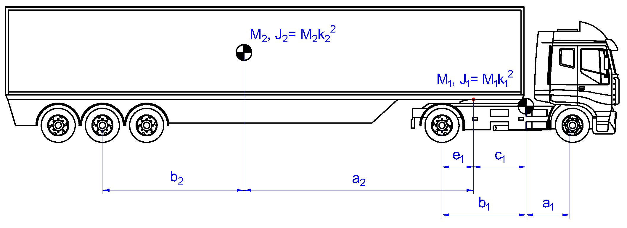
Figure 4.
System variables definition.
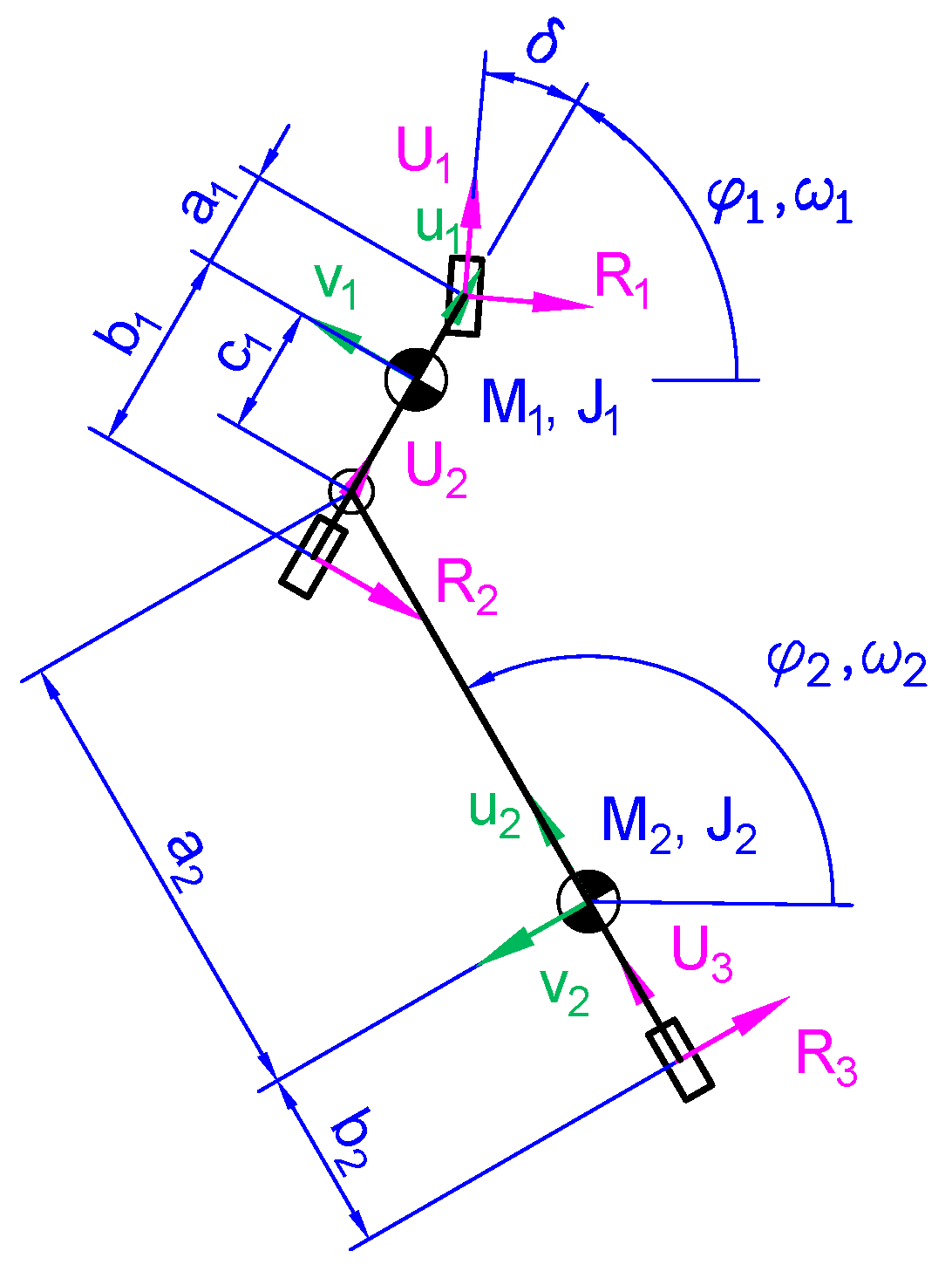
Figure 5.
Errors to be minimized in the cost function.
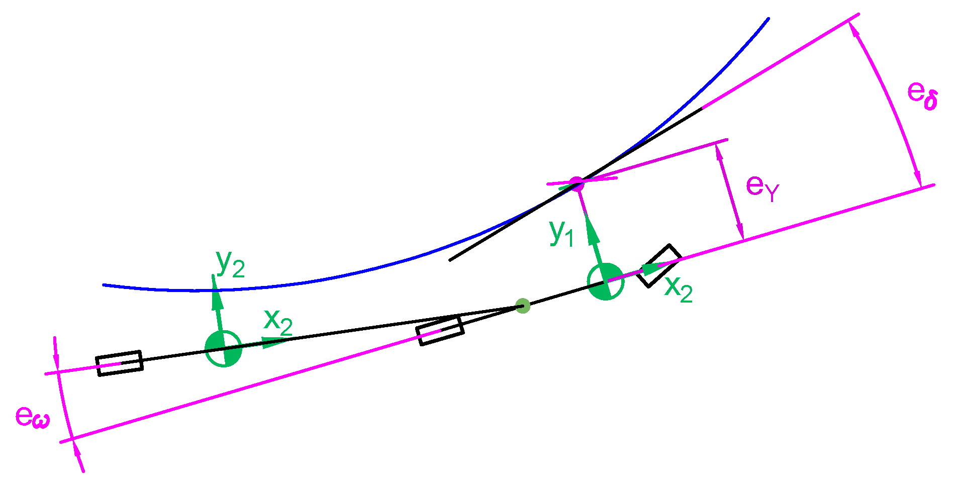
Figure 6.
Trailer behavior without stability controller for vref = 15m/s.
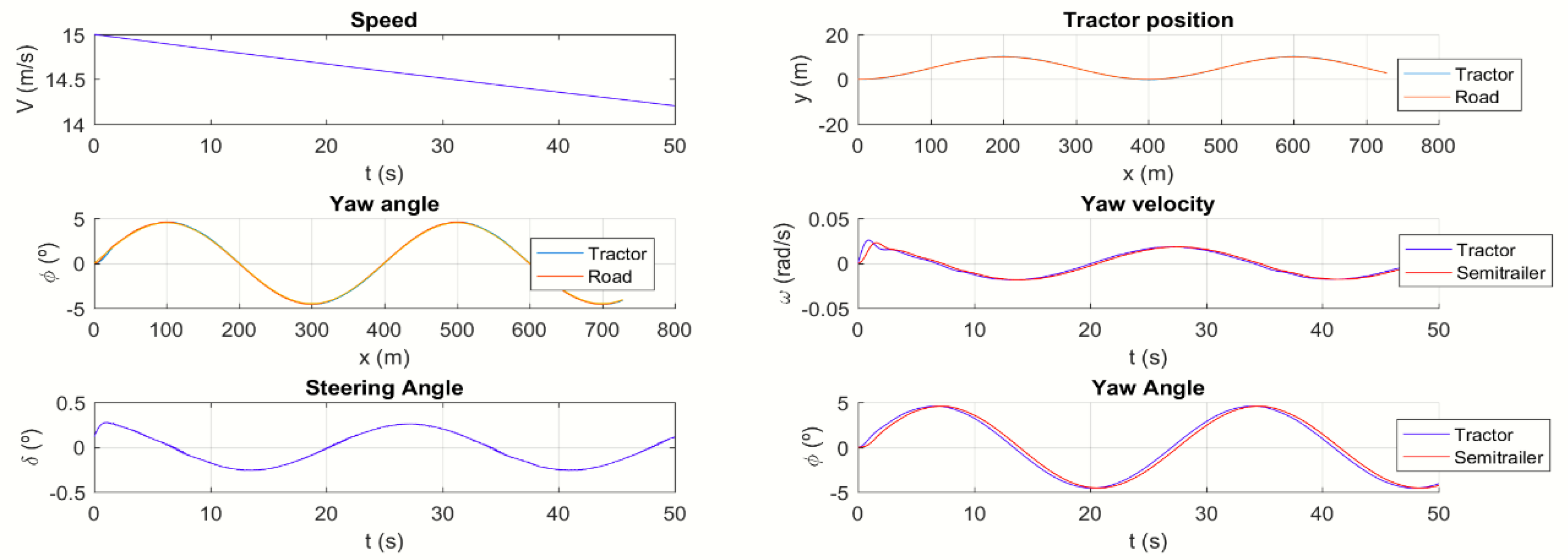
Figure 7.
Trailer behavior with stability controller for vref = 15m/s.
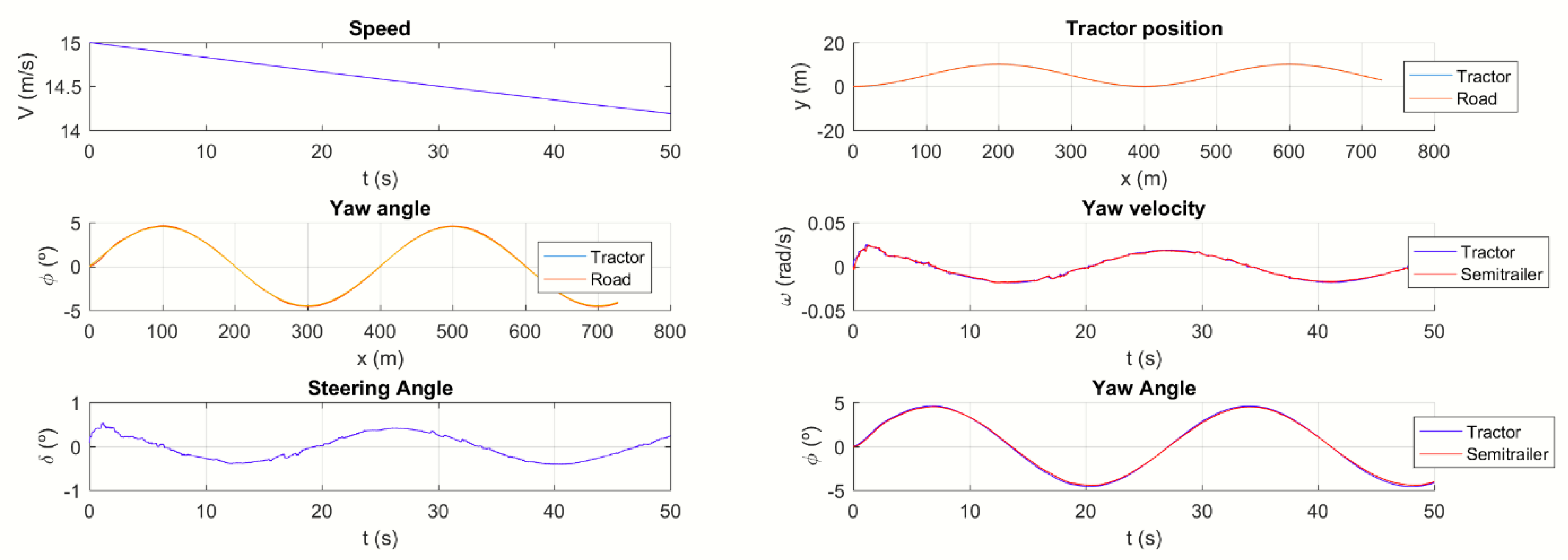
Figure 8.
Tracking errors for vref = 15m/s.
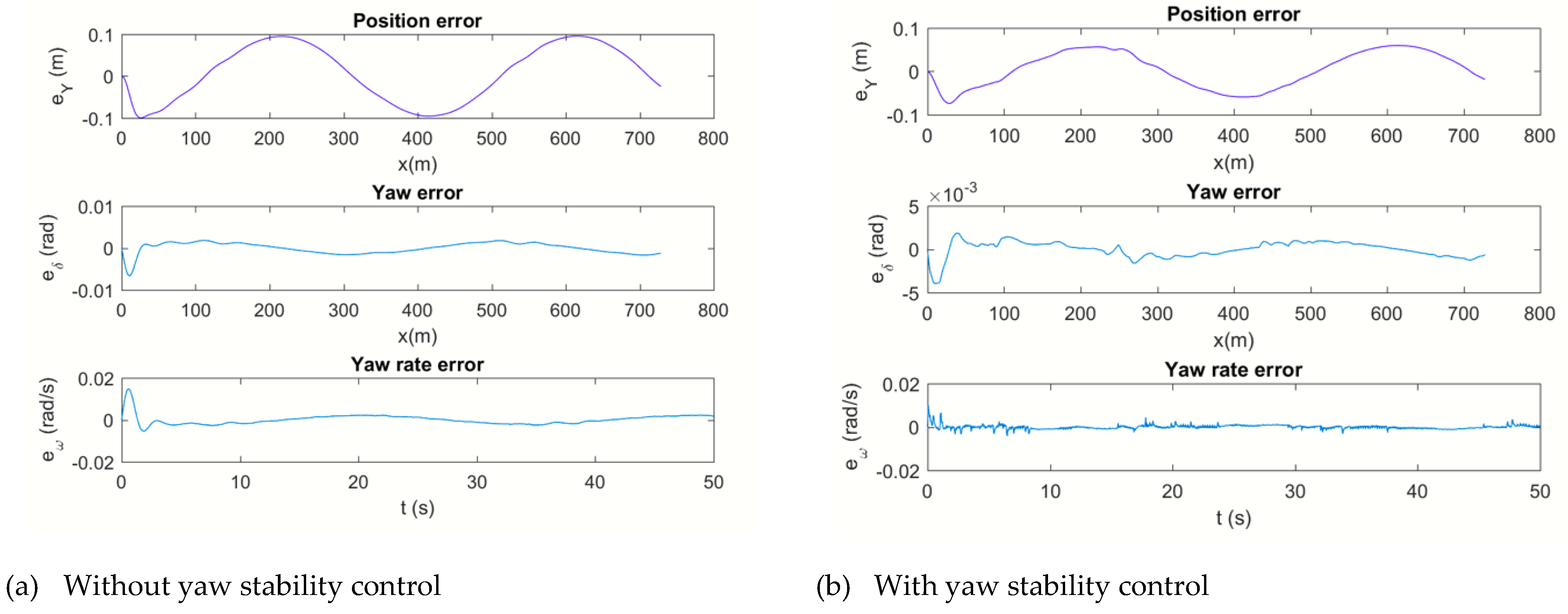
Figure 9.
Trailer behavior without stability controller for vref = 35m/s.
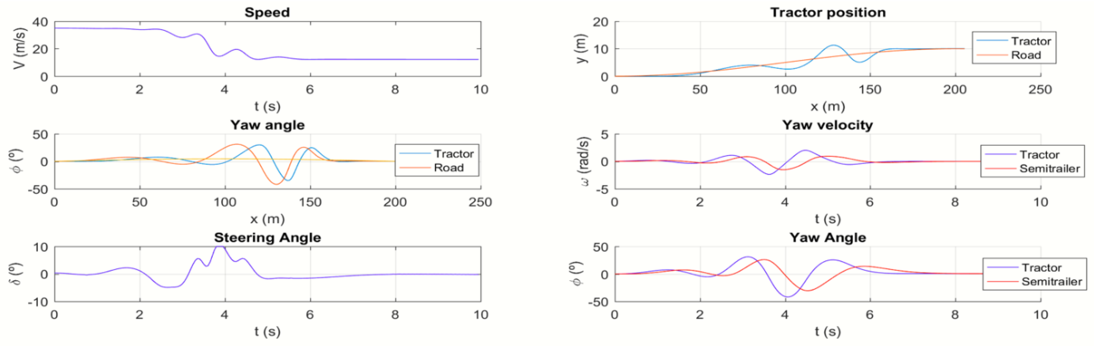
Figure 10.
Trailer behavior with stability controller for vref = 35m/s.
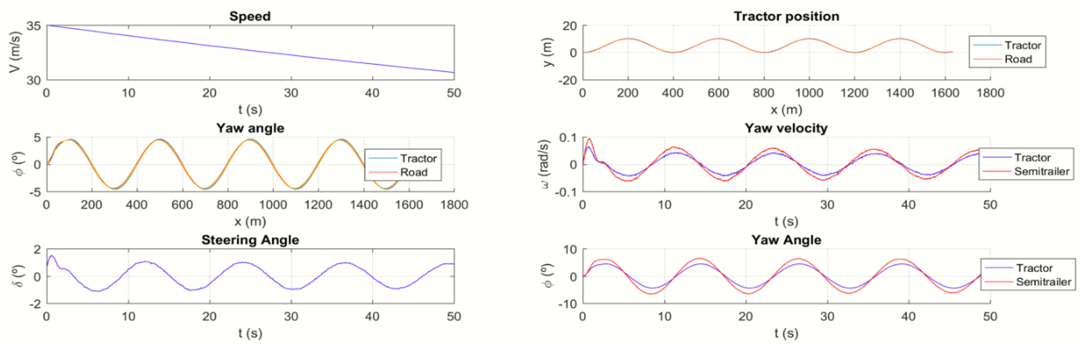
Figure 11.
Tracking errors for vref = 35m/s.
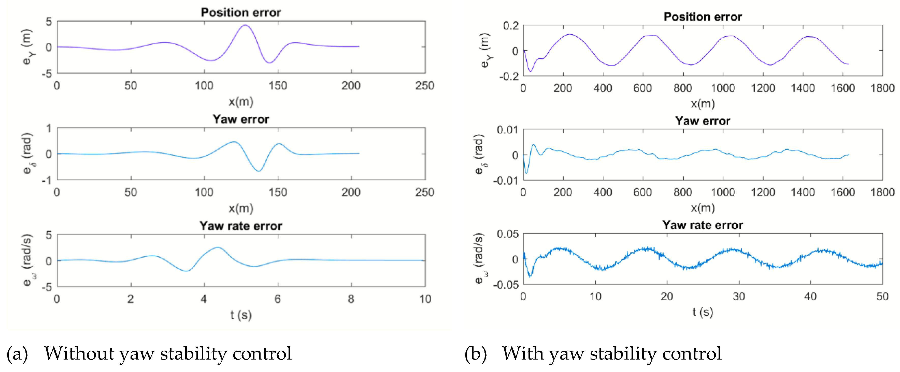
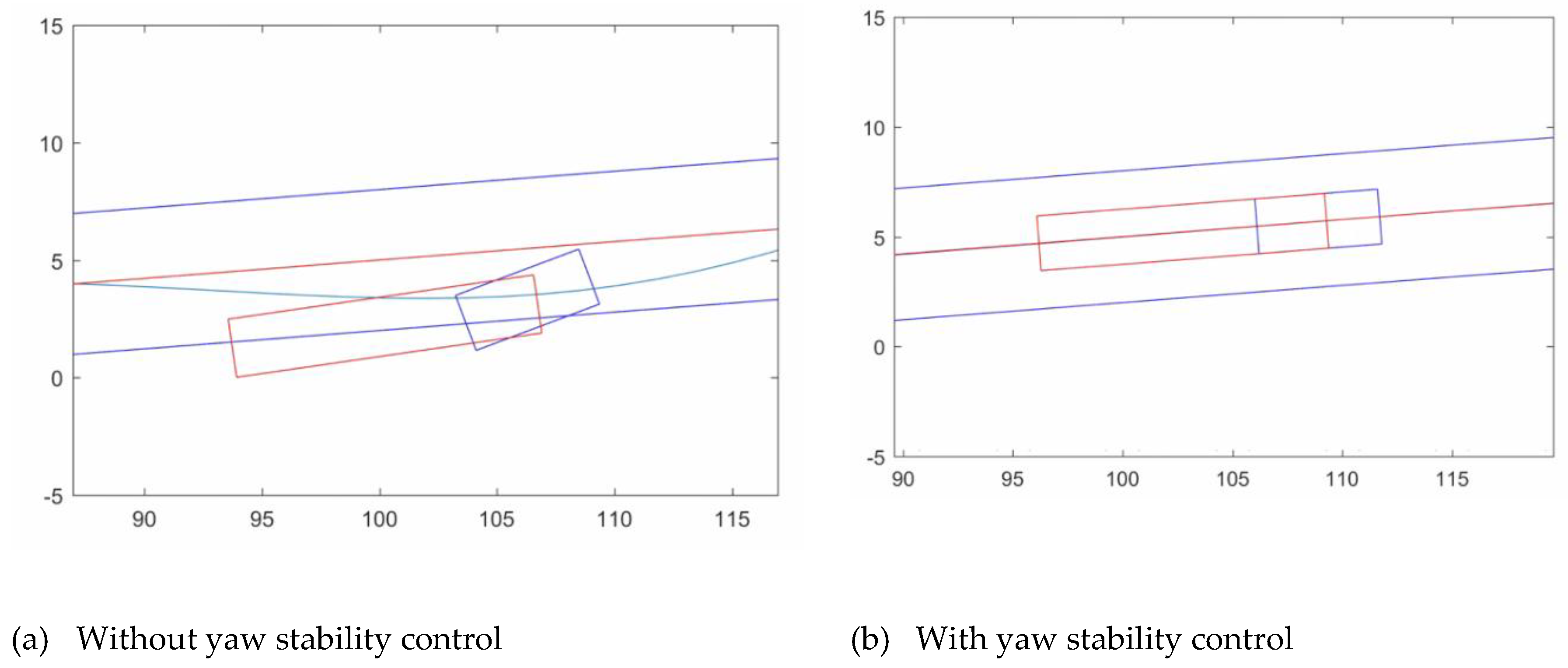
Figure 12.
Pictures of the trailer movement for vref = 35m/s.
Video 1.
Videos of the trailer movement for vref = 35m/s
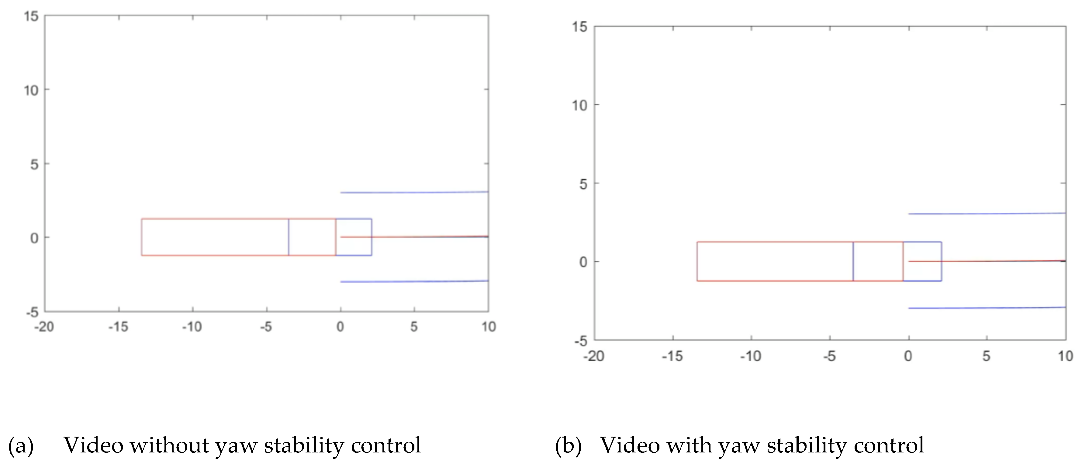

Table 1.
Control Methodologies for Articulated Vehicle Stability.
| Control Approach | Key Studies | Characteristics |
| Model Predictive Control | [14,15,16] | Optimization-based, predictive capability, handles constraints |
| Fuzzy Logic / Fuzzy PID | [17,18] | Robust to parameter uncertainty, intuitive rule design |
| Sliding Mode Control | [19,20] | Robust against disturbances, invariant to matched uncertainty |
| LQR/Optimal Control | [21] | Optimal performance, requires accurate model |
| Adaptive Control | [22,23] | Handles parameter variations, loading changes |
| Integrated Multi-system Control | [16,24,25] | Coordinates multiple actuators for enhanced performance |
Table 2.
Control parameters based on the instability mode.
| Parameter Type | Studies Using This Parameter |
| Yaw rate | [17,20,24,25] |
| Sideslip angle | [17,19,30] |
| Articulation/hitch angle | [14,19,20] |
| Fifth wheel angle | [23] |
| Yaw moment | [25] |
Table 3.
Comparative effectiveness of braking configurations for yaw and sway stability.
| Configuration | Studies | Findings |
| Tractor only | [1,20] | Effective for yaw control but limited trailer influence |
| Trailer only | [22,24,31,32] | Direct trailer stabilization, effective for sway control |
| Both units | [14,15,17,19] | Superior performance, comprehensive stability control |
Disclaimer/Publisher’s Note: The statements, opinions and data contained in all publications are solely those of the individual author(s) and contributor(s) and not of MDPI and/or the editor(s). MDPI and/or the editor(s) disclaim responsibility for any injury to people or property resulting from any ideas, methods, instructions or products referred to in the content. |
© 2026 by the authors. Licensee MDPI, Basel, Switzerland. This article is an open access article distributed under the terms and conditions of the Creative Commons Attribution (CC BY) license (http://creativecommons.org/licenses/by/4.0/).
Copyright: This open access article is published under a Creative Commons CC BY 4.0 license, which permit the free download, distribution, and reuse, provided that the author and preprint are cited in any reuse.


