
Submitted:
31 December 2025
Posted:
01 January 2026
You are already at the latest version
Abstract
In this paper, the proposed work provided a comprehensive review of non-isolated, isolated and optimization techniques for Direct Current (DC) to DC converters. This survey work is focused on their application in solar Photovoltaic (PV) based renewable energy systems. An important reason for considering these converters is that, critical components in power electronics are used to efficiently manage energy conversion and distribution. The DC-DC converter is categorized as a non-isolated and isolated DC-DC converter. The non-isolated converters are used where a direct electrical connection between input and output is acceptable, which makes it simpler and more efficient. Also, isolated DC-DC converters provide an electrical partition between input and output in high-voltage applications or where noise isolation is necessary. Also, optimization methods are used to improve the performance and efficiency of DC-DC converters. These techniques maximize energy extraction and minimize the losses especially renewable energy systems to ensure optimal operation. Overall, the review provides the latest advancements in DC-DC converter and optimization strategies. The significant improvement is the efficiency and effectiveness of renewable energy systems.
Keywords:
DC-DC converter
; solar photovoltaic (PV)
; non-isolated converters
; isolated converters
; optimization techniques
; maximum power point tracking (MPPT)
I. Introduction
Fossil fuel extraction has significantly impacted the rapid increase in an environment that prompts the growth of interest in renewable energy sources. Many researchers explored and developed a renewable energy technology [1]. Solar PV has gained popularity to generate power. Solar PV systems have several benefits like longer operational lifespan, low impact on the environment, minimal maintenance and the ability to generate sufficient power to vary load demands. Solar energy is a renewable resource that can be harnessed worldwide which is the best alternative to electricity generated from fossil fuels [2].
To attain a high voltage of PV for various applications, the DC-DC converters are very essential for power electronic interfacing [3]. It is designed to process the DC loads as mode-switching regulators. It is used to adjust the voltage of DC to an appropriate level by managing an output. All the converters use a power switching control for switch on and off behaviours. This converter used to pair with Maximum Power Point Tracking (MPPT) systems and crucial to load matching and maximising the PV power output. However, the minimum PV output voltages have fluctuated due to shading effects, ambient temperature, solar irradiance, surface cleanliness and mismatches among modules. These factors can significantly impact the DC output voltage’s stability [4].
To address these challenges, DC-DC converter designs are developed to provide a stable output voltage and accommodate the low PV voltage fluctuations [5]. These converters have been developed for solar PV systems since the 1920s and these converters are increasing the solar energy harvesting systems [6]. This voltage is regulated appropriately using PV panels as a power source. While selecting a DC-DC converter, criteria like high efficiency, low conduction, cost-effectiveness and losses in switching are considered. As a result, researchers continuously develop innovative new types of DC-DC converter topologies.
This paper provides various DC-DC converters and their classification in Section 2. The Section 3 survey has a non-isolated DC-DC converter that was recently developed in solar energy harvesting systems. Next, the various isolated types of DC-DC converters are reviewed in Section 3 which discusses the topology of it. Then Section 5 provides an optimization-based DC-DC converter that is suitable for PV energy applications.
II. Classification of DC-DC Converters
The higher growth of power converters has advanced the electrical engineering field significantly. Traditional power converters are essential due to their unique characteristics and applications [7]. This section presents the various types of DC-DC converters and their classification used in PV systems.
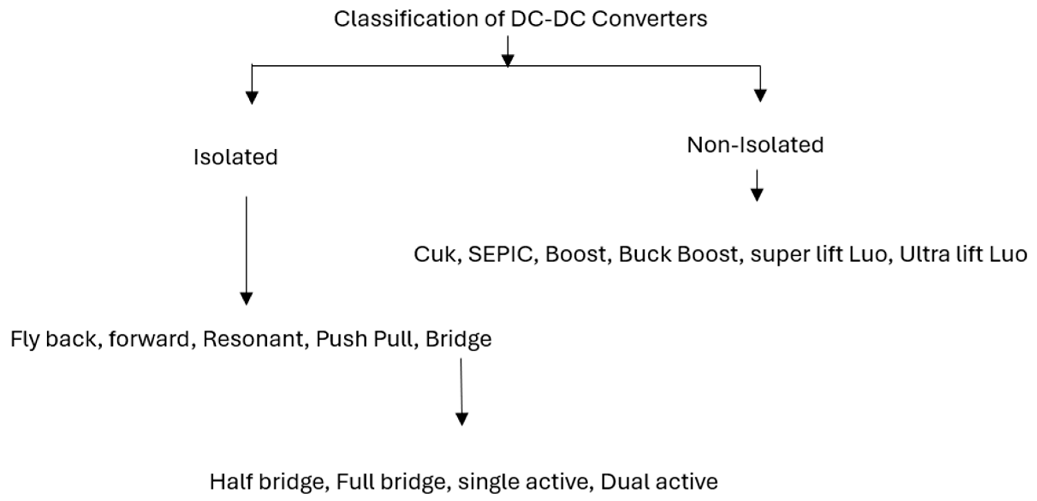
DC-DC converters are classified into two categories [8] such as isolated and non-isolated converters are shown in Figure 1. Isolated converters are used to process an electrical barrier between an input and output which is implemented using a high-frequency transformer. It is beneficial for high-voltage and configured for either positive or negative outputs [9]. For example, the converters like resonant, flyback, push-pull, forward and bridge are isolated converters. Next, the non-isolated converters which lack electrical isolation such as buck-boost, Cuk, boost, SEPIC, Super-Lift Luo and so on are commonly used non-isolated converters for several applications [10].
Figure 1.
Classification of DC-DC Converters.
III. Non-Isolated DC-DC Converters
Buck Converter:
Aihsan et al. [11] developed a buck converter to reduce the voltage from a PV DC. It is designed to test an outcome in the ranges of 5VDC at 1.0A and 5VDC at 0.5A respectively. To ensure a consistent power supply, a battery storage system was integrated that was enhanced by a charge controller to extend battery life. It also provides multiple low-voltage outputs.
To optimize power extraction, nMPPT is used by Singh et al. [12] who explored MPPT to extract maximum power from PV panels. Mishra et al. [13] designed an MPPT technique that calculated parameters like battery voltage, PV array current and voltage as well as the power output. It has a buck-boost converter of non-inverting that is effective for PV applications and shows a 12.2V battery voltage, 0.31A PV array current, 34V PV array voltage, 23mW PV panel power and 21.8mW output power.
Şahin et al. [14] examined enhancing solar energy utilization such as PV-powered energy as hydrogen and PV cars that store energy as hydrogen. Both scenarios are efficient in the conversion and storage of hydrogen energy. Sharma et al. [15] presented a PV-based DC-DC buck converter to harvest energy in Wireless Sensor Networks (WSN) that a limited in WSN nodes as battery life.
Cuk Converter:
Liu et al. [16] designed a Cuk converter with an integration of a charging equalizing converter (ICEC). In this converter design, a Voltage Multiplier (VM) replaces the capacitor to process a charging equalizer driven by the voltage ripple that acts as an AC voltage source.
Celentano et al. [17] designed a Cuk converter for an IS analysis on individual solar panels in PV plants based on its design and sizing. Shayeghi et al. [18] developed a modified step-up converter derived using a voltage-lift method that improves voltage gain by adding a capacitor and diode. Themozhi et al. [19] discussed an interleaved Cuk converter between a PV source and an inverter. It improves a continuous current supply and minimises torque ripple in induction motors. Devi et al. [20] explored the bidirectional Cuk converter to loads and storage systems that provide a comparative analysis by choosing an optimal control for specific applications.
Buck-Boost Converter:
Pires et al. [21] introduced a single switch and buck-boost converter to offer a voltage gain. It is used to reduce an input current ripple and minimise the voltage stress on switches. Krishnaveni et al. [22] presented two-switch buck-boost converters and Reddy et al. [23] described a buck-boost converter in Continuous Conduction Mode (CCM) under steady-state conditions with a lower voltage stress on switches and diodes. Monteiro et al. [24] developed a buck-boost converter which has a duty cycle range to enable the operation to allow an output voltage below high duty cycles with an input voltage. Pandey et al. [25] designed a bidirectional DC-DC power flow converter that combines the buck and boost converters in an anti-parallel pattern. It is adapted to modifying irradiance conditions, battery charging and has discharging characteristics.
SEPIC Converter:
Kumar et al. [26] presented a SEPIC converter to reduce the common issues in DC converters like high ripple, harmonics, voltage inversion, overheating and efficiency loss. Hadji et al. [27] developed a modified SEPIC converter with an Incremental Conductance (INC) MPPT controller to extract high power. Selvabharathi et al. [28] simulated Boost, Cuk and SEPIC converters with MPPT methods. Selvaraj et al. [29] combined a SEPIC converter with a genetic method to achieve the flexibility to handle variable input voltages and optimization capabilities. Emar et al. [30] developed a hysteresis current-mode regulated DC-DC converter to attain a 10% Total Harmonic Distortion (THD) and efficiency among 95-97%.
Luo Converter:
Banupriya et al. [31] presented a double-lift Luo converter named a dual-output DC-DC converter. Femi et al. [32] utilized a Positive Output-Super Lift (PO-SL) Luo converter to achieve a high gain and optimize PV power extraction that is fed to a PWM rectifier. Kamaraj et al. [33] developed a modified multiport Luo converter using a voltage lift method while Rajan et al. [34] designed a modified Luo converter attached to a grid to improve the usage of renewable energy and efficiency. Khalil et al. [35] presented a POSL Luo converter using an MPPT method for PV systems. The features of Non-Isolated DC-DC Converters are given in Table 1.
IV. Isolated Converters
Flyback Converter:
Shanmugasundaram et al. [36] designed a two-stage boost-flyback converter which has a boost as input voltage and the flyback used to transfer energy and regulate an output voltage. Cruz-Cozar et al. [37] analyzed a forward-flyback boost converter with resonant behaviour, to attain higher energy than the prior flyback. Afshari et al. [38] explored a universal flyback solar micro-converter that is used for DC and single-phase AC grids. This method employs an identical semiconductor to minimise redundancy. Choudhary et al. [39] developed a flyback converter that combined with insolation, temperature and load conditions. Abbasi et al. [40] a DC-DC/AC flyback converter with minimal components and a dynamic voltage conversion ratio that suits DC or AC grids.
Forward Converter:
Pol et al. [41] developed a modified forward converter with a mixed-stranded transformer winding method to attain an efficient isolated boost converter. Matiushkin et al. [42] studied advanced forward DC-DC converters combined with clamped output capacitors that transferred a transformer’s energy to the output. In another work, Matiushkin et al. [43] employed a hill-climbing MPPT method for closed-loop systems that adjustment to attain maximum power. Another study by Matiushkin et al. [44] presented a piggyback converter as a cost-effective one with an additional clamped output capacitor.
Resonant Converter:
Kwon et al. [45] proposed an alternative Series Resonant Converter (SRC) that achieves a current ripple, minimises volume and improves efficiency by partial power SRC stage. Alnuman et al. [46] designed a single-phase PV coupled with a SEPIC converter with MPPT. Shankar et al. [47] presented a PV-based dual-phase resonant converter for battery swapping and modifying vehicle voltage and fast charging in rural areas. Barnawal et al. [48] designed an isolated dual half-active bridge resonant converter using a grey wolf optimization for the MPPT model.
Push-Pull Converter:
Wu et al. [49] developed an active-clamped push-pull converter for the PV method that has a minimum input current pulsation, a high conversion ratio of voltage and zero-voltage and zero-current switching for switches and diodes. Wu et al. [50] simulated an improved active clamp push-pull full-bridge converter with capacitor clamping. Miranda-Terán et al. [51] developed a modified current-fed push-pull converter with an active clamping circuit’s primary-side switches to reduce the voltage spikes. Ivanovic et al. [52] analysed power losses in push-pull converters that convert dynamic power losses. Alam et al. [53] explored a high-gain push-pull converter that has a push-pull inverter, a rectifier circuit and a C-filter to attain the desired DC voltage. The feature comparison of different Isolated DC-DC Converters is given in Table 2.
The overall comparison between Isolated and Non-Isolated DC-DC Converters are given in Table 3.
V. Optimization Techniques
Several researchers have applied an optimization strategy in DC-DC converters to improve the performance and efficiency of PV systems. Optimization techniques are essential to attain the performance of non-isolated and isolated converters. These techniques are used to enhance efficiency, voltage regulation, power density and thermal management.
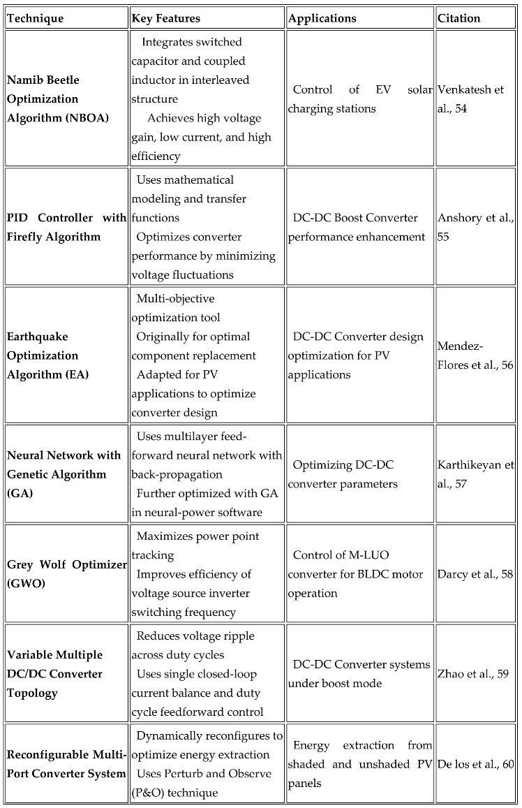
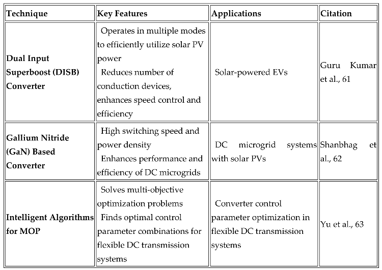
Venkatesh et al. [54] presented the Namib Beetle Optimization Algorithm (NBOA) to manage the electric vehicle operation in PV charging stations. It combined the switched capacitor principles and a coupled inductor into an interleaved converter. It delivered the high voltage gain to maintain the low current and high efficiency to optimize the EV performances.
Anshory et al. [55] focused on reducing voltage fluctuations and enhancing the overall Boost Converter performances. It involved the converter circuit using transfer functions that were followed by the Proportional Integral Derivative (PID) controller and the Firefly optimization. This method achieved the stability and efficiency of the converter's operation effectively.
Mendez-Flores et al. [56] explored earthquake optimization to design multi-objective converters. This method is adapted to showcase its versatility and effectiveness for PV in managing diverse optimization challenges.
Karthikeyan et al. [57] utilized a multilayer feed-forward neural network trained with a back-propagation method to optimize the converter’s parameters. It is refined with a Genetic Algorithm (GA) to maximise the predictive accuracy and converter performance.
Darcy et al. [58] discussed a Grey Wolf Optimizer (GWO) to control a Luo converter. This optimization method was effective in improving MPPT for smoothening brushless DC motors. Therefore, the efficiency of the voltage source switching frequency improves a motor's overall performance.
Zhao et al. [59] presented variable multiple converters to reduce ripple over duty cycles. This system structure is under boost mode and processes a single closed-loop current balance and duty cycle feed forward control. This optimization model reduces the voltage ripple and improves system stability.
De los et al. [60] developed a reconfigurable multi-port converter system that is used to extract energy from shaded and unshaded PV panels. Using a Perturb and Observe (P&O) method, it optimized an energy extraction by dynamically reconfiguring the system and enhancing overall efficiency.
Guru Kumar et al. [61] provided a Dual-Input Super-Boost (DISB) that is used to operate multiple modes efficiently to enhance the PV system. This method attained speed control and minimised the number of conduction devices required in every mode. It enhances the converter's efficiency and varies an operating condition.
Shanbhag et al. [62] examined a Gallium Nitride (GaN) converter for PV within a DC microgrid application. Because of the superior switching speed and power density of GaN devices, it improves the performance and efficiency of microgrids significantly. Lastly, Yu et al. [63] discussed an intelligent method for Multi-Objective Optimization (MOO) issues in flexible DC systems. Overcoming these complex issues and providing an optimal control parameter, contributes to optimising a converter control to ensure better system performance and stability. The overall comparison of optimization-based converters is given in Table 4.
VI. Results & Finding
RESULTS & FINDINGS:
Figure 1.
caption.
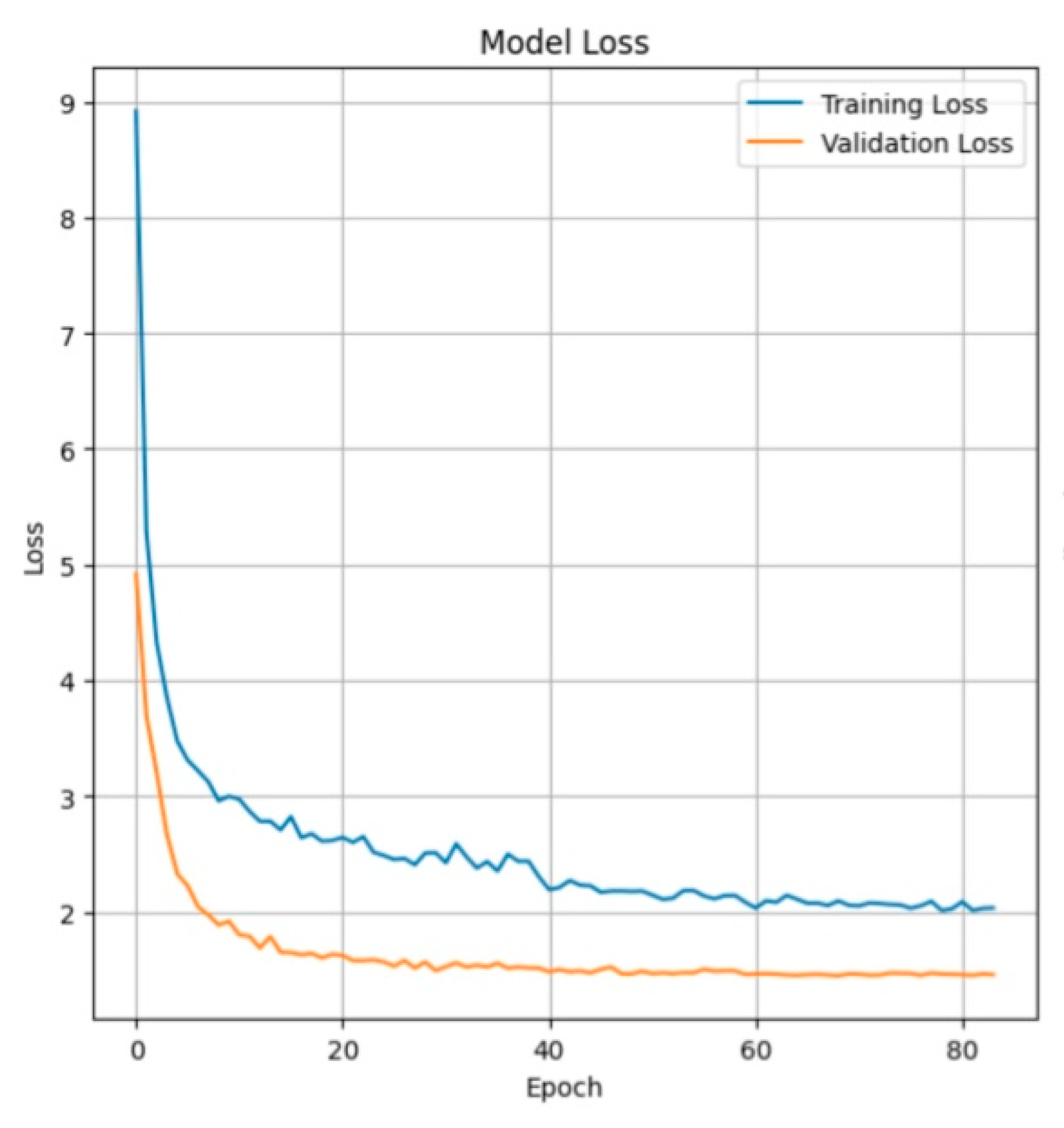
Figure 2.
Caption.
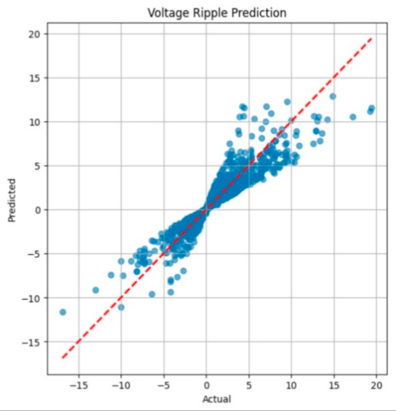
Figure 1 represents following explanation
1. Initial High Loss and Rapid Decrease (Epochs 0–15)
• Both the Training Loss and Validation Loss start very high (Loss ≈9\approx 9 for training, ≈5\approx 5 for validation).
• The loss for both datasets decreases very rapidly in the initial epochs. This is typical for a neural network where the model is quickly adjusting its weights to capture the fundamental patterns in the data.
2. Convergence and Generalization (Epochs 15–80)
• As the training progresses, the rate of loss decrease slows down significantly, and the model begins to converge.
• The Validation Loss (Orange Line) is consistently lower than the Training Loss (Blue Line) across the entire plot, especially after the initial rapid decrease.
o Training Loss settles around 2.02.0.
o Validation Loss settles around 1.51.5.
• Significance: This pattern, where the validation loss is lower than the training loss, suggests the model is generalizing very well. The model is performing better on the unseen validation data than on the training data.
o Possible reasons for lower validation loss: The validation set might be "easier" to predict, or techniques like regularization (which penalizes complexity during training, inflating the training loss) might be in use, which are often switched off during validation or testing.3. Final State
Figure 2
represent Interpretation of Model Performance
The model's performance is judged by how closely the blue data points cluster around the red dashed line:
High Performance/Accuracy: The vast majority of the data points are tightly clustered on or very close to the red line. This indicates that the model's predictions align very closely with the actual observed values.
Observed Performance: In this plot, the data points show a strong, positive correlation and are tightly clustered around the ideal Y=XY=X line, particularly in the central region (around 0 to ±5\pm 5 on the axes). This suggests the model is performing exceptionally well at predicting the voltage ripple.
Increasing Variance at Extremes: As the actual voltage ripple values move toward the extremes (i.e., less than −10-10 or greater than 1010), the scatter of the blue points widens slightly. This indicates that the model's predictions have slightly more error (higher variance) for the largest absolute voltage ripple values, which is common as these extreme values are usually less frequent in the training data.
Figure 3.
Caption.
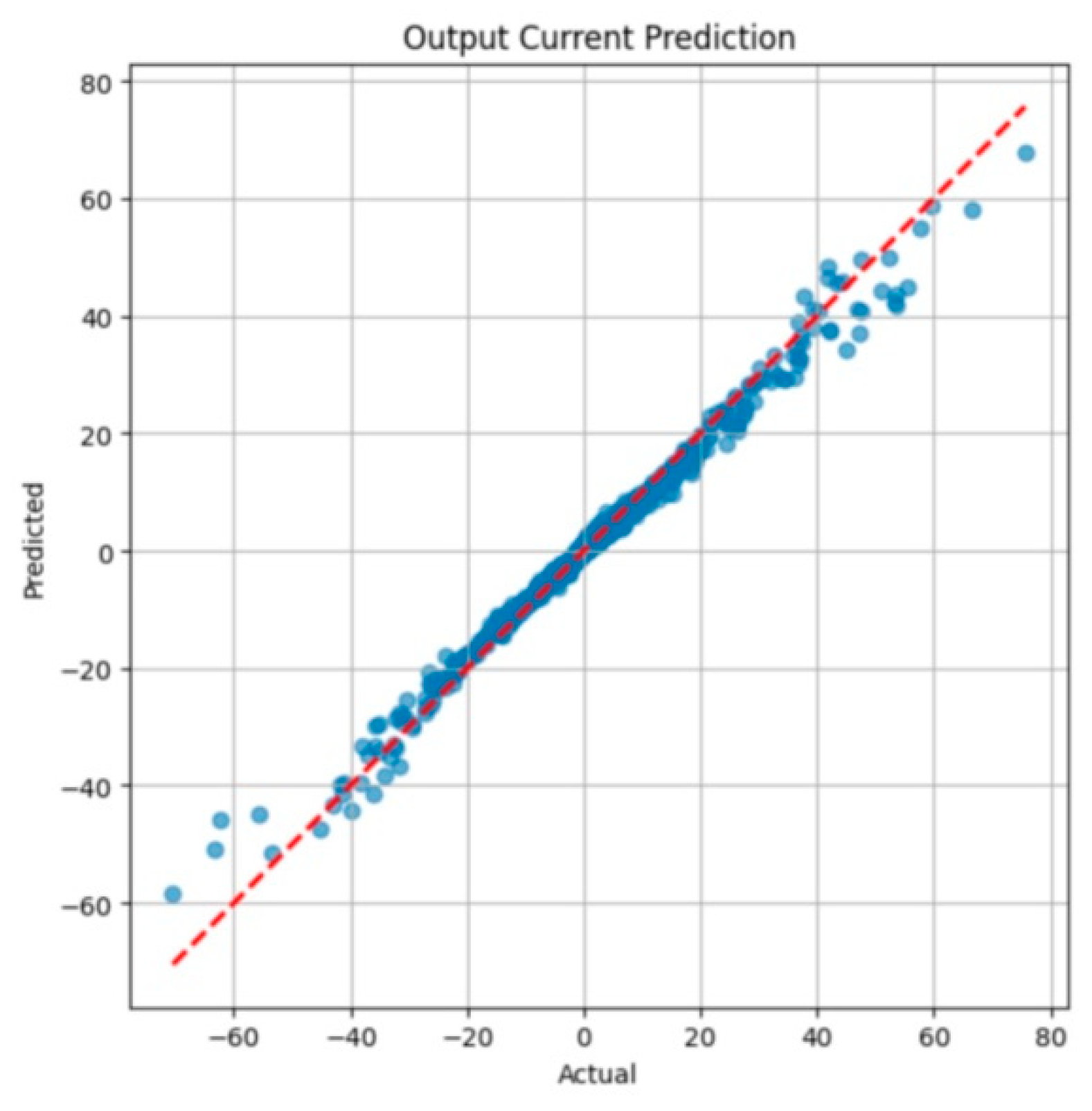
Figure 4.
caption.
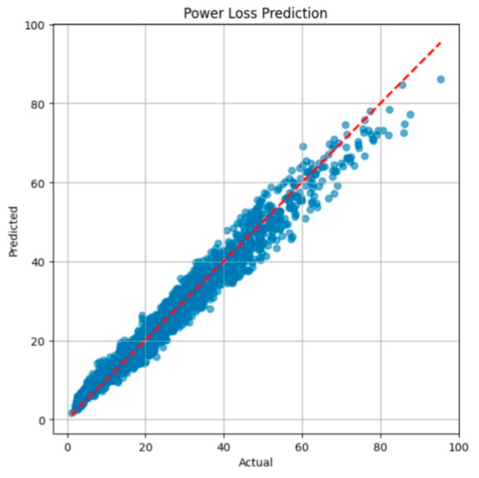
Figure 3 shows very high performance and accuracy in predicting the output current across the entire range of values (from approximately -60 to 70).
• Strong Correlation: The blue data points are extremely tightly clustered around the red dashed line. This visually confirms a near-perfect correlation between the actual and predicted output current.
• Low Error: The minimal scatter around the Y=X line indicates a very low Root Mean Square Error (RMSE) and Mean Absolute Error (MAE). The model's predictions consistently match the actual measurements.
• Consistency Across Range: Unlike the previous voltage ripple plot, this model maintains high prediction accuracy even at the more extreme current. This suggests the model was trained on a comprehensive dataset that included sufficient samples of high and low current states.
Figure 4 indicates that the model is performing well, but with a noticeable increase in uncertainty as the power loss increases.
1. Strong Central Performance (Low Power Loss): For low power loss values (below approximately 40), the data points are tightly clustered around the red dashed line. This confirms the model is highly accurate and reliable for small power loss predictions.
2. Increasing Scatter (High Power Loss): As the actual power loss increases (from 40 up to 100), the scatter of the blue data points widens significantly. This indicates that the model's predictions have higher variance and larger errors when predicting high power loss values.
o For example, when the actual power loss is 80, the model's predictions can range from approximately 65 to 85.
3. Overall Accuracy: Despite the increased scatter at higher values, the model still maintains a strong positive correlation and is successfully predicting the trend of power loss. It appears to slightly underpredict some of the highest actual values (e.g., the points near the X=95 mark are generally below the Y=X line).
Converter Topology Efficiency Comparison
| Converter Type | Topology Type | Average Efficiency (ηavg) |
| Buck Converter | Non-Isolated (Step-Down) | 0.8980 (Highest) |
| Boost Converter | Non-Isolated (Step-Up) | 0.8695 |
| Buck-Boost Converter | Non-Isolated (Step-Up/Down) | 0.8513 |
| SEPIC Converter | Non-Isolated (Step-Up/Down, Non-Inverting) | 0.8415 |
| Cuk Converter | Non-Isolated (Step-Up/Down, Inverting) | 0.8328 |
| Luo Converter | Non-Isolated | 0.8227 |
| Non-Isolated Converters | Average | 0.8786 |
| Isolated Converters | Average | 0.8266 |
Key Findings:
• Buck Converter Dominance: The Buck Converter exhibits the highest average efficiency (0.8980), which is typical as its simpler structure often results in lower component losses (like conduction losses in the diode/synchronous rectifier).
• Topology Grouping: The Non-Isolated Converters show a significantly higher average efficiency (0.8786) compared to the Isolated Converters (0.8266). This is expected because isolated topologies, which require a transformer, inherently introduce additional core and winding losses.
Optimal Operating Points
| Metric | Value | Significance |
| Max Efficiency (η_max) | 0.9500 (95.00%) | Represents the highest achieved efficiency across all tested operating points and converter types, demonstrating the system's potential under ideal conditions. |
| Average Duty Cycle for Optimal (D_avg) | 0.6407 | The mean duty cycle required to achieve the top 10 most efficient operating points. A duty cycle D=0.6407 is close to the operating point where the output voltage is slightly higher than or around the input voltage (for buck-derived topologies). |
VII. Conclusions
This review provided the importance of choosing the right type of DC-DC converter such as non-isolated or isolated based on applications. It reviewed the recent types of non-isolated converters such as buck and boost types that do not require electrical isolation among the input and output and attained simplicity and cost-effectiveness. Conversely, isolated converters like flyback and forward provide an essential electrical separation to reduce safety and noise which is suitable for high-voltage applications. Also, the review processes the significant impact of the advanced optimization model on the performance of these converters. Methods like GA and artificial intelligence are used in converters for fine-tuning to achieve optimal efficiency and change the conditions in PV systems. Therefore, the Continued innovation in converter design and optimization is presented in advancing power electronics and provides the growing demand for efficient and sustainable energy solutions.
References
- Zeng J., Ning J., Du X., Kim T., Yang Z., & Winstead, V. (2019). A Four-Port DC–DC converter for a standalone wind and solar energy system. IEEE Transactions on Industry Applications, 56(1), 446-454.
- Karthikeyan V., Kumaravel S., & Gurukumar G. J. I. T. O. C. (2019). High step-up gain DC–DC converter with switched capacitor and regenerative boost configuration for solar PV applications. IEEE Transactions on Circuits and Systems II: Express Briefs, 66(12), 2022-2026. [CrossRef]
- Revathi B. S., Mahalingam P., & Gonzalez-Longatt F. (2019). Interleaved high gain DC-DC converter for integrating solar PV source to DC bus. Solar energy, 188, 924-934. [CrossRef]
- Kumaravel S., Achathuparambil Narayanankutty R., Rao V. S., & Sankar A. (2019). Dual Input–Output DC–DC converter for solar PV/battery/ultra-capacitor powered electric vehicle application. IET Power Electronics, 12(13), 3351-3358.
- Das M., Pal M., & Agarwal V. (2019). Novel high gain, high efficiency dc–dc converter suitable for solar PV module integration with three-phase grid tied inverters. IEEE journal of photovoltaics, 9(2), 528-537.
- Zulkifli M. Z., Azri M., Alias A., Talib N., & Lazi J. M. (2019). Simple control scheme buck-boost DC-DC converter for stand alone PV application system. Int J Pow Elec & Dri Syst ISSN, 2088(8694), 1091.
- Raj A., Arya S. R., & Gupta J. (2020). Solar PV array-based DC–DC converter with MPPT for low power applications. Renewable Energy Focus, 34, 109-119.
- Shanmugam S. K., Muthusamy K., Sennippan V., Balasubramaniam S., & Ramasamy S. (2019). Modelling of solar photovoltaic array fed brushless DC motor drive using enhanced DC-DC converter. Proc Romanian Acad Series A, 20, 169-178.
- Ravindranath Tagore, Y., Rajani K., & Anuradha K. (2022). Dynamic analysis of solar powered two-stage dc–dc converter with MPPT and voltage regulation. International Journal of Dynamics and Control, 10(6), 1745-1759. [CrossRef]
- Li R., & Shi F. (2019). Control and optimization of residential photovoltaic power generation system with high efficiency isolated bidirectional DC–DC converter, IEEE access, 7, 116107-116122.
- Aihsan M. Z., Kimpol N., Fang L. H., Fahmi M. I., Mustafa W. A., Jobran J. A. M., & Kader M. M. A. (2020, September). Solar powered multiple output buck converter. In IOP Conference Series: Materials Science and Engineering (Vol. 932, No. 1, p. 012075), IOP Publishing.
- Singh S. N. (2017). Selection of non-isolated DC-DC converters for solar photovoltaic system, Renewable and Sustainable Energy Reviews, 76, 1230-1247. [CrossRef]
- Mishra D. P., Senapati R., & Salkuti S. R. (2022). Comparison of DC-DC converters for solar power conversion system. Indonesian Journal of Electrical Engineering and Computer Science (IJEECS), 26(2), 648-655. [CrossRef]
- Şahin M. E. (2019). An Efficient Solar-Hydrogen DC-DC buck converter system with sliding mode control. El-Cezeri, 6(3), 558-570.
- Sharma H., Sharma M., Sharma C., Haque A., & Jaffery Z. A. (2018, November). Performance analysis of solar powered DC-DC buck converter for energy harvesting IoT nodes. In 2018 3rd International Innovative Applications of Computational Intelligence on Power, Energy and Controls with their Impact on Humanity (CIPECH) IEEE (pp. 26-29),.
- Liu Y., Lin Z., & Xu B. (2024). An Integrated charging equalizing converter based on Cuk converter for solar home system, IET Power Electronics, 17(10), 1251-1261.
- Celentano L., De Riso M., Di Palo R., Coppola M., Guerriero P., & Daliento S. (2024, June). A new modelling approach for a Cuk converter for on-field diagnostics of PV modules. In 2024 International Symposium on Power Electronics, Electrical Drives, Automation and Motion (SPEEDAM), IEEE (pp. 1236-1241).
- Shayeghi H., Mohajery R. E. Z. A., Hosseinpour M., Sedaghti F., & Bizon N. (2024). A transformer-less high voltage gain DC-DC converter based on Cuk converter and voltage-lift technique. Journal of Energy Management and Technology, 8(1), 23-34.
- Themozhi G., Srinivasan K., Srinivas T. A., & Prabha A. (2024). Analysis of suitable converter for the implementation of drive system in solar photovoltaic panels. Electrical Engineering & Electromechanics, (1), 17-22. [CrossRef]
- Devi V. V., & Manthati U. B. (2024, February). Comparitive Study of Solar PV with Bidirectional CUK Converter for BESS. In 2024 IEEE International Conference on Computing, Power and Communication Technologies (IC2PCT), IEEE (Vol. 5, pp. 372-377).
- Pires V. F., Foito D., Cordeiro A., & Silva J. F. (2024, June). A New Single-Switch Wide Voltage Gain Nonisolated DC-DC Buck-Boost Converter Integrating a Switched Inductor Network. In 2024 IEEE 18th International Conference on Compatibility, Power Electronics and Power Engineering (CPE-POWERENG), IEEE (pp. 1-6).
- Krishnaveni S., & Gomathi S. (2024, June). Analysis of modified Buck-Boost Converter in Battery charging system by using solar energy. In 2024 International Conference on Advancements in Power, Communication and Intelligent Systems (APCI), IEEE (pp. 1-5).
- Reddy B. N., Goud B. S., Sai Kalyan C. N., Balachandran P. K., Aljafari B., & Sangeetha K. (2023). The Design of 2S2L-Based Buck-Boost Converter with a Wide Conversion Range. International Transactions on Electrical Energy Systems, 2023(1), 4057091. [CrossRef]
- Monteiro J., Pires V. F., Foito D., Cordeiro A., Silva J. F., & Pinto S. (2023). A Buck-Boost Converter with Extended Duty-Cycle Range in the Buck Voltage Region for Renewable Energy Sources. Electronics, 12(3), 584. [CrossRef]
- Pandey K. K., Kumar M., Kumari A., & Kumar J. (2021). Bidirectional DC-DC buck-boost converter for battery energy storage system and PV panel. In Modeling, Simulation and Optimization: Proceedings of MSO 2020 (pp. 681-693), Springer Singapore.
- Kumar S., Kumar R., & Singh N. (2017, March). Performance of closed loop SEPIC converter with DC-DC converter for solar energy system. In 2017 4th International Conference on Power, Control & Embedded Systems (ICPCES), IEEE (pp. 1-6).
- Hadji S., Belkaid A., Larbi L., Colak I., Kayisli K., & Aissou S. (2024, May). High Gain Voltage SEPIC Converter for PV System. In 2024 12th International Conference on Smart Grid (icSmartGrid), IEEE (pp. 618-622).
- Selvabharathi P., Veerakumar S., & Kannan V. K. (2021, March). Simulation of DC-DC converter topology for solar PV system under varying climatic conditions with MPPT controller. In IOP Conference Series: Materials Science and Engineering (Vol. 1084, No. 1, p. 012084). IOP Publishing.
- Selvaraj L., Vaigundamoorthi M., & Ramkumar M. S. (2024, April). Improved Energy Harvesting in Photovoltaic Systems using SEPIC Converter. In 2024 International Conference on Inventive Computation Technologies (ICICT), IEEE (pp. 1905-1910).
- Emar W. (2024). Hysteresis current-mode regulated modified sepic-buck converter used for solar photovoltaic systems. Arabian Journal for Science and Engineering, 1-25. [CrossRef]
- Banupriya R., & Nagarajan R. (2022). Performance Analysis of a Relift Luo Converter-Derived Dual-Output DC to DC Converter for Microgrid Applications. International Journal of Photoenergy, 2022(1), 8093589. [CrossRef]

Table 1.
Comparison of Different Non-Isolated DC-DC Converters.
| Type | Key Features | Applications | Advantages | Limitations |
|---|---|---|---|---|
| Buck Converter | Steps down the voltage, simple and efficient | PV energy harvesting, WSN power management | High efficiency, simple control | Limited to step-down applications |
| Cuk Converter | Provides continuous current, improves ripple control | PV inverters, motor drives | Improved current regulation | Requires additional components |
| Buck-Boost Converter | Capable of stepping up or down voltage | Battery charging, PV systems | Flexible voltage control, works in wide ranges | Higher voltage stress on switches |
| SEPIC Converter | Provides positive output voltage, low ripple | PV systems, reducing voltage ripple and harmonics | Reduces voltage inversion and harmonics | Slightly more complex than buck-boost converter |
| Luo Converter | High-voltage gain, positive and negative outputs | PV power optimization, renewable energy grids | Optimizes power extraction, high gain | More complex due to super-lift stages |
Table 2.
Comparison of Different Isolated DC-DC Converters.
| Type | Key Features | Applications | Advantages | Limitations |
|---|---|---|---|---|
| Flyback Converter | Simple design, suitable for low-power applications | Solar micro-converters, DC-AC systems | Compact, cost-effective | Limited to low-power applications |
| Forward Converter | Higher efficiency, uses transformer to transfer energy | PV-based isolated systems, battery charging | High efficiency, good for medium-power levels | Requires additional clamping circuitry |
| Resonant Converter | Soft-switching techniques for high efficiency | Battery swapping, fast charging systems | Minimizes current ripple, high power density | Complex control and design |
| Push-Pull Converter | High voltage conversion ratio, reduces voltage spikes | High-gain PV systems, transformers with isolation | Zero-voltage switching, minimal input pulsation | Requires precise transformer design |
Table 3.
Advantages of Isolated vs. Non-Isolated DC-DC Converters.
| Feature | Isolated Converters | Non-Isolated Converters |
|---|---|---|
| Electrical Isolation | Provides galvanic isolation between input and output | No electrical isolation between input and output |
| Safety | Safer for high-voltage applications | Less safe in high-voltage scenarios |
| Complexity | Higher complexity due to transformers and isolation | Simpler design, lower component count |
| Cost | More expensive due to additional components | More cost-effective due to simpler design |
| Size | Bulkier due to transformers | More compact, especially at low power |
| Efficiency | Slightly lower efficiency in some designs | High efficiency, especially in low-power applications |
| Applications | Suitable for AC grids, high-voltage systems | Commonly used in low-power, low-voltage applications |
Table 4.
Comparison of Optimization Techniques in DC-DC Converters.
Disclaimer/Publisher’s Note: The statements, opinions and data contained in all publications are solely those of the individual author(s) and contributor(s) and not of MDPI and/or the editor(s). MDPI and/or the editor(s) disclaim responsibility for any injury to people or property resulting from any ideas, methods, instructions or products referred to in the content. |
© 2026 by the authors. Licensee MDPI, Basel, Switzerland. This article is an open access article distributed under the terms and conditions of the Creative Commons Attribution (CC BY) license (http://creativecommons.org/licenses/by/4.0/).
Copyright: This open access article is published under a Creative Commons CC BY 4.0 license, which permit the free download, distribution, and reuse, provided that the author and preprint are cited in any reuse.


