Submitted:
30 December 2025
Posted:
31 December 2025
You are already at the latest version
Abstract
Web openings are created in reinforced concrete deep beams for various purposes. The CFRP strengthening technology is commonly employed to mitigate the adverse consequences of these openings. The impact of openings generated in areas of stirrupless or by arranging the stirrups at the bottom and top chords of the opening in a closed configuration has been examined in numerous studies. However, in reality, stirrup damage frequently occurs when openings are made due to the high number of stirrups employed in deep beams. In this study, three specimens tested in a previous experimental study were modeled via ABAQUS, and the results obtained were validated by comparing them with the experimental results. To create openings of varying sizes in the elements, the reinforcements were cut, and these beams were strengthened with CFRP laminates, followed by a parametric study. The findings indicated a 56% reduction in the load-carrying capacity of the unstrengthened beam (h = 500 mm) featuring a 300 mm diameter opening, alongside an 87% decrease in energy dissipation. Although the diameter of the opening, which was formed by cutting the stirrups, is less than one-third of the beam's height, the application of 1.8 mm thick laminates resulted in only limited improvement.
Keywords:
CFRP (carbon fiber-reinforced polymer)
; deep beam
; web opening
; FEM (finite element model)
1. Introduction
Reinforced concrete deep beams are widely used, especially in high-rise buildings, because they possess high shear capacity. Web openings of various shapes and sizes are drilled in these beams to provide infrastructure services such as power lines, water lines, telephone networks, and gas, etc. [1,2]. These openings can be drilled during the construction phase of the beam, tailored to the project, or they can be drilled later if necessary. Because core drilling is often used, circular openings are common [3].
Necessary precautions are taken for planned openings during the design phase. However, openings drilled later disrupt the normal stress flow that would occur under load and cause cracks to form at the edges of the opening [2]. These cracks, caused by stress concentrations at the edges of the openings, reduce the stiffness of the element and, consequently, its load-carrying capacity [4,5,6,7,8,9,10,11,12,13,14,15,16,17].
Studies have indicated that the rate of change in the load-carrying capacity depends on the location and size of the opening. In a study investigating the effects of openings drilled at different locations [18], wider diagonal cracks formed when the opening was located in the shear span than when the opening was located outside the shear span of the beam element. Another study [19] indicated that having an opening in the middle of the beam did not significantly alter the behavior of the element and that crack formation and failure mode varied depending on the opening location. When the opening was located in the load flow path, the load-carrying capacity and ductility of the beam decreased significantly compared with those in other situations [10]. Additionally, studies have shown that symmetrical openings yield more negative results than asymmetrical openings located in the middle of the element [20,21].
Not only the location of the openings but also their size is an important factor influencing the behavior. When different opening diameters and reinforcement ratios were used in two-opening beams, the load-carrying capacity and toughness decreased as the opening diameter increased, but the ductility change was not significant [22]. For elements with multiple circular openings, the opening diameter was found to be more effective than the shear span length, and the opening size had a dominant effect on the element's performance of the element [23]. In the study by Ali and Saeed [24], increasing the opening size significantly reduced the shear strength of the element, resulting in a decrease in performance.
Structures are designed to maintain their functionality over a long period, encompassing decades [25,26]. Therefore, it is necessary to prevent deterioration that may arise from subsequent interventions. Special strengthening applications are available to limit crack widths in the element and prevent premature failure of its strength [27]. Among these applications, carbon fiber-reinforced polymers (CFRPs) stand out because they are relatively easy to apply to beams with large openings and are supported by studies showing that they improve element performance. In a series of experiments using CFRPs, the stiffness capacity of beams with large circular and square openings increased by 33% and 17%, respectively [17]. Wrapping the square opening with CFRP increased the element's capacity by 54% [8], whereas applying the same application to a beam with a large circular opening increased the ultimate load capacity by 15.32% [28]. Experimental studies have demonstrated that CFRP laminates have positive effects on the initial crack load [29] and ultimate load-carrying capacity [5,13], as well as the cracking pattern of the element.
However, these studies were conducted on deep beams with predesigned openings. These openings were created either in areas without reinforcement or by configuring the upper and lower stirrups in a closed configuration. In real life, however, not only the web reinforcement but also the stirrups are cut to create openings, which unintentionally reduces the performance of the element.
Owing to various difficulties, conducting experiments is not always possible. Therefore, the use of finite element programs is becoming increasingly common among researchers. In this study, the ABAQUS finite element program was used to investigate the effects of cut circular symmetric web openings on the structural performance of the deep beams. The numerical models were validated by comparison them with the experimental results reported in the study by Jasim et al. [29]. Afterwards, the effects of strengthening the elements with circular openings of different sizes using CFRP laminates of varying thicknesses on the performance of the element were studied parametrically, and the results are presented in this article.
2. Materials and Methods
In the present study, the beam arrangement evaluated by Jasim et al. [29] was used to investigate the effect of the openings, which are created by cutting the element, on the performance of deep beams (Figure 1). Three elements were selected from this study: one without an opening (DP-S1), one with a symmetrical square opening (200 200 mm) (DP-S1-C-O1-WS), and one strengthened with CFRP around the opening (DP-S1-C-O1-S). All three elements had a length of 1500 mm, a cross-sectional area of 150 500 mm, and a shear span-to-depth ratio of 1.1. The general reinforcement applied to all three elements is given in Figure 1, and the mechanical properties of the concrete and steel used are listed in Table 1 and Table 2.
The experimental elements were modeled and analyzed using the ABAQUS finite element program. The results were compared with the experimental results to verify the validity of the model. The consistency of the results made it possible to use the model in parametric studies. Studies on deep beams with openings have shown that the most unfavorable results occur in elements with symmetrical web openings [20,21], so a symmetrical opening was adopted in this study. To evaluate the effect of the opening diameter on the performance of the element, diameters of 150 mm, 200 mm, 250 mm, and 300 mm were considered. The minimum diameter was chosen to the same as the element width. By choosing the largest diameter as 300 mm, only the continuity of the top compression and bottom tension reinforcement was ensured. Each element was then strengthened with 1.0 mm, 1.4 mm, and 1.8 mm thick CFRP laminates, and the analyses were repeated, and the results were compared.
3. Numerical Model
3.1. Model Description
The experimental elements from the study of Jasim et al. [29] were modeled using full-size finite element models (FEMs). The elements were modeled as simply supported beams with pin-roller supports (Figure 2). The pin support point was fully constrained in the X, Y, and Z directions, whereas the roller support section was modeled to be limited to translation only in the vertical direction. To prevent the monotonic displacement protocol applied through static analysis from causing damage to the concrete at both the loading and support points, 20 mm-high and 100 mm-wide steel plates were modeled. The plates, modeled as discrete rigid plates, were connected to the concrete with tie connections.
Achieving realistic behavior in finite element method applications is closely related to the accurate modeling of material behavior. To simulate elastic stiffness deterioration in concrete resulting from both tensile and compressive plastic stresses, it is necessary to utilize structural models from the literature. The widely used model among these models is the Damage Plasticity Model [30,31]. This model is used in the ABAQUS finite element program under the name Concrete Damage Plasticity (CDP). The parameters required for the CDP application in ABAQUS and their values used in the analyses are given in Table 3.
The model developed by Saenz [32] was used to describe the compressive behavior of concrete. The model proposed by Nayal and Rasheed [33] and subsequently developed by Wahalathantri et al. [34] to prevent sudden deformation was used to describe the behavior of concrete in tension. This model has been previously used in other studies and has been proven to be useful in accurately predicting the behavior of the element [29,35,36]. The behavior of the steel reinforcement was considered bilinear isotropic, as defined by Jasim et al. [29]. The values required for this description are given in Table 1. Furthermore, the Poisson's ratio and modulus of elasticity were assumed to be 0.3 and 200 GPa, respectively. The concrete-reinforcement connection was achieved through an embedment connection, assuming a perfect bond between the reinforcement and the concrete.
The CFRP material was modeled under the assumption of linear elastic isotropic behavior. Because the material is essentially orthotropic due to its unidirectional nature, it stretches in the fiber direction under load, and therefore the modulus in the fiber direction will determines the behavior. From this perspective, it would be appropriate to use isotropic behavior as a proxy for the behavior of a CFRP material under loading [37]. Here, the assumption is that brittle fracture will occur when the material reaches its ultimate tensile strength [38]. Studies modeling the interaction between CFRPs and concrete have shown that this approach yields highly effective results [37,38,39]. This method was also adopted in the current study, and the CFRP laminates were connected to the concrete using a tie connection to prevent shear damage.
A sensitivity study of the generated models demonstrated that a 25 mm mesh size was sufficient to capture the load-displacement relationship. Although a 20 mm mesh size is generally adopted in studies [3,29,40], studies by Gokul et al. [41] and Al-Thairy et al. [42] also showed that 20 mm and 25 mm mesh sizes do not significantly affect the load-displacement curve results. Considering the analysis times when 20 mm and 25 mm mesh sizes are selected, the use of 25 mm mesh size was adopted as sufficient in all the models.
3.2. Model Verification
The load-displacement curves and crack formation patterns obtained from the finite element analyses are compared with the experimental results in Figure 3 and Figure 4. When the results were evaluated in terms of load-displacement capacities and possible crack formation patterns, the utility of FEMs in parametric studies was confirmed.
In the experimental study, the stirrups around the openings of the elements with openings were produced closed (DP-S1-C-O1-WS and DP-S1-C-O1-S). For this reason, all the stirrups were modeled as closed during the modeling process of experimental elements. However, in the elements, there is a cutting of the stirrups in the openings created later. Therefore, to see the effects of closed and open-ended stirrups on the performance of the element, the DP-S1-C-O1-WS element was remodeled and analyzed with the stirrup ends open (Figure 5 and Figure 6).
The load-displacement relationships obtained from analyses for both open and closed forms of the stirrups is shown in Figure 5. In the element with closed stirrups, the maximum displacement and load values are 3.78 mm and 200.22 kN, respectively, whereas in the element with open stirrup ends, these values are 3.59 mm and 177.09 kN, respectively. In this case, if the stirrups are cut, the displacement value decreases by approximately 5%, whereas the load-carrying capacity decreases by 11.55%. Figure 6 shows the distribution of Von Mises stress and the formation of concrete tensile damage (DAMAGET). In the DAMAGET model, the red areas indicate tensile damage. When the stirrups are closed, the reinforcement stress is greater than when they are open-ended. In contrast, in the element where the stirrup ends are open, more cracks form, especially above the spans, due to the reduced contribution of the stirrups. Additionally, a slight reduction was observed in the red areas of the crush zones located at the corners of the element when open-ended stirrups were used.
4. Parametric Study
After validating the FEMs, a parametric study was conducted to investigate the effects of the opening size and the strengthening of the elements with CFRP laminates of different thicknesses (1.0 mm, 1.4 mm, and 1.8 mm) on the behavior of deep beams with openings created by cutting the reinforcements. Experimental studies have indicated that the most unfavorable results among holes opened at different locations are caused by those in the shear path [10,18,19] and by symmetrically placed openings [20,21]. For this reason, as shown in Figure 7, symmetrical openings with diameters (D) of 150 mm, 200 mm, 250 mm, and 300 mm were created in both cut openings, and these elements were then strengthened with CFRP laminates of different thicknesses. In this study, all the properties, such as the material properties, reinforcement configuration, and dimensions, were kept the same as those of the elements taken from the study by Jasim et al. [29]. Figure 8 shows the reinforcements that need to be cut to create the openings. Excluding the DP-S1, which was treated as a control element, 16 finite element models were created and cross-comparisons were made. The effects of the opening size and CFRP thickness were evaluated in the comparisons. The elements used in the parametric study are named to include the opening diameter and the CFRP thickness. For example, elements with an opening diameter of 150 mm, unstrengthened and strengthened with 1.0 mm CFRP, are named D150-0.0 and D150-1.0, respectively.
5. Results and Discussions
For elements consisting of four series (D150 series, D200 series, D250 series, and D300 series), the effect of the opening size was first evaluated by comparing the unstrengthened elements of each series. The DAMAGET results for these four elements are given in Figure 9. In element D150-0.0, a diagonal crack occurred, starting from the support point and extending toward the point where the load was applied. It was observed that as the opening diameter increased, shear-compression damage occurred at the chord near the loading point because of both the stirrup ratio and the decrease in the concrete area. The FEM analysis of the test element DP-S1 was used for control purposes and was designated DP-S1_FEM. Figure 10 shows comparisons of the load-displacement curves between the unstrengthened elements and DP-S1_FEM. In addition, the maximum damage load (), maximum displacement (), normalized load (), energy consumption capacity (), and normalized energy consumption () values used in the comparisons are given in Table 4. The normalized load was calculated as the ratio of the maximum load of the elements to the maximum load obtained from DP-S1_FEM. The energy consumption amount, an important parameter indicating the seismic behavior of the element, was obtained by calculating the area under the load-displacement curve. The normalized form of the energy consumption amount was calculated as the ratio of the energy consumption amounts of the elements to the energy consumption amount of DP-S1_FEM. As can be seen in Figure 10, as the span ratio increases, both the maximum load capacity and the consumption ratio decrease. As can be seen in Table 4, the maximum load capacity decreased by 23% for the 150 mm opening, 40% for the 200 mm opening, 46% for the 250 mm opening, and 56% for the 300 mm opening. The energy consumption capacities decreased by 27%, 48%, 56%, and 87%, respectively. These results indicate that the openings created in the shear span significantly reduce the performance of the element.
The effects of CFRP laminates of different thicknesses on the load-displacement curves of the elements are shown separately for each group in Figure 11. It was observed that the maximum load-carrying capacity and displacement ratios increased in the strengthened elements. The values used for comparisons are given in Table 4. For each series, the initial stiffness of the elements used in the CFRP laminates slightly increased. A clearer comparison of the performance of the elements is shown in Figure 12. In the normalized load vs. laminate thickness relationship given in Figure 12, it is observed that the load capacity increases with increasing laminate thickness in all series. However, this increase was not uniform across all the elements. For elements with 1.0 mm laminates, the increase in the D150 series was 13%, whereas it was 15% for D200, 9% for D250, and 5% for D300. When 1.4 mm and 1.8 mm laminates were used, these values were obtained in the same order as 17% - 36% - 15% - 9% and 21% - 53% - 24% - 18%, respectively. Even if the lamination thickness is increased for large opening sizes, the load-carrying capacity of the element does not increase significantly. However, when a 1.8 mm thick laminate is used, the maximum load-carrying capacities of the 150 mm and 200 mm diameter openings are nearly equal. The same graph shows that the maximum load-carrying capacities of all the elements are below the boundary line formed by the DP-S1_FEM element, which is considered the control element.
The normalized energy consumption versus laminate thickness curves in Figure 12 indicate that the amount of energy consumption increases as the opening diameter decreases and the laminate thickness increases. The increase in energy consumption is expected to be due to the increased load-carrying capacity and displacement values resulting from the contribution of laminates. Among the elements used 1.0 mm laminate, the increase in the D150 series was 4%, while it was 27% for D200, 11% for D250, and 123% for D300. When using 1.4 mm and 1.8 mm laminates, these values were obtained in the same order as 14% - 35% - 25% - 161% and 21% - 70% - 41% - 223%. The element rigidity is expected to decrease as the opening diameter increases. However, at a 300 mm opening, unlike the other elements, all the longitudinal reinforcements except for the bottom tensile and top compressive reinforcements were cut (Figure 8). Since the chords remaining at the top and bottom of the opening are transformed into a single-reinforced section, these areas are more prone to compression failure compared to other elements. Therefore, it is likely that the laminated effect will be more pronounced. The 1.8 mm laminates also caused the energy consumption of the D150 and D200 elements to be quite close. As with the maximum load-carrying capacity, the energy consumption capacities of the elements with web openings were below that of the control element.
6. Conclusions
This study investigated the effects of cut circular web openings in the shear span on the behavior of deep beams. In a parametric study conducted using the finite element method, the effects of the opening diameter and CFRP laminate thickness were investigated. On the basis of the findings of the study, the following conclusions can be drawn:
- The results have shown that the use of finite element models is suitable for analyzing deep beams. When the analysis results are compared with the experimental results, it is evident that finite element models can predict not only the load-displacement relationships but also crack formation and failure modes with high accuracy.
- The capacity of deep beams manufactured with stirrups closed in the top and bottom chords is not the same as that of beams with openings created later by cutting the stirrups. The load-carrying capacity of the element with cut stirrups was found to be 11.5% lower than that of the beam with the planned opening. The maximum displacement is also 5% lower.
- While shear damage was expected in the beams, shear-compression damage also occurred due to the increase in the opening diameter.
- The capacities of the unstrengthened elements decreased significantly. The load-carrying capacity of the element with a 150 mm opening decreased by 23%, that with a 200 mm opening decteased by 40%, that with a 250 mm opening decreased by 46%, and that with a 300 mm opening decreased by 56%. Energy consumption has also decreased because the load-carrying capacity and displacement amount have decreased with increasing opening diameter. The energy consumption rates of the unstrengthened elements with openings decreased by 27%, 48%, 56%, and 87%, respectively.
- Although the use of CFRP laminates increased the capacity of the elements, the capacity of the elements with openings remained below that of the elements without openings.
- Even when a high-thickness CFRP laminate is used for strengthening, the load-carrying and energy consumption capacities of elements with an opening diameter greater than half the element height can reach only half the capacity of the element without an opening.
- For openings to be created later in the shear spans of deep beams, the maximum diameter should be less than half of the height of the beam and appropriately strengthened.
- In deep beams with closely spaced reinforcement, where the diameters of the cut circular symmetrical openings in the shear spans are larger than the transverse reinforcement spacing, it should be assumed that the capacity of the beam will be lower than the initial state even if CFRP strengthening is applied.
Funding
This research received no external funding.
Institutional Review Board Statement
Not applicable.
Informed Consent Statement
Not applicable.
Data Availability Statement
The data presented in this study are available on request from the author.
Conflicts of Interest
The author declares no conflicts of interest.
References
- Shabanlou, M.; Meghdadi, Z.; Ghaffar, S.H. Experimental and Analytical Study of the Residual Performance of Reinforced Concrete Deep Beams with Circular Web Openings. Results Eng. 2025, 25, 104229. [Google Scholar] [CrossRef]
- Ghalla, M.; Shaaban, I.G.; Elsamak, G.; Badawi, M.; Alshammari, E.; Yehia, S.A. Restoration of Shear Capacity in RC Beams with Cut Circular Web Openings Using Stainless Steel, Aluminium Sheets, and GFRP Bars. Eng. Struct. 2025, 334, 120215. [Google Scholar] [CrossRef]
- Özkılıç, Y.O.; Aksoylu, C.; Gemi, L.; Arslan, M.H. Behavior of CFRP-Strengthened RC Beams with Circular Web Openings in Shear Zones: Numerical Study. Struct. 2022, 41, 1369–1389. [Google Scholar] [CrossRef]
- Abdullah, G.M.S.; Alshaikh, I.M.H.; Zeyad, A.M.; Magbool, H.M.; Bakar, B.H.A. The Effect of Openings on the Performance of Self-Compacting Concrete with Volcanic Pumice Powder and Different Steel Fibers. Case Stud. Constr. Mater. 2022, 17, e01148. [Google Scholar] [CrossRef]
- Alyaseen, A.; Poddar, A.; Alissa, J.; Alahmad, H.; Almohammed, F. Behavior of CFRP-Strengthened RC Beams with Web Openings in Shear Zones: Numerical Simulation. Mater. Today Proc. 2022, 65, 3229–3239. [Google Scholar] [CrossRef]
- Amin, H.M.; Agarwal, V.C.; Aziz, O.Q. Effect of Opening Size and Location on the Shear Strength Behavior of RC Deep Beams Without Web Reinforcement. Int. J. Innovative Technol. Exploring. Eng. 2013, 3, 28–30. [Google Scholar]
- Amiri, J.V.; ALibygie, M.H. Effect of Small Circular Opening on the Shear and Flexural Behavior and Ultimate Strength of Reinforced Concrete Beams Using Normal and High Strength Concrete. In Proc. 13th World Conf. on Earthquake Engineering, Canada (August 2004).
- Chin, S.C.; Shafiq, N.; Nuruddin, M.F. Strengthening of RC Beams with Large Openings in Shear by CFRP Laminates: Experiment and 2D Nonlinear Finite Element Analysis. Res. J. Appl. Sci. Eng. Technol. 2012, 4, 1172–1180. [Google Scholar]
- Diggikar, R.; Mangalgi, S.; Harsoor, R. Behavior of RCC Beam with Rectangular Opening Strengthened by CFRP and GFRP Sheets. In Proc. Int. Conf. on Recent Innovations in Civil Engineering, Germany (October 2013).
- Hassan, H.M.; Arab, M.A.E.S.; Ismail El-Kassas, A. Behavior of High Strength Self Compacted Concrete Deep Beams with Web Openings. Heliyon. 2019, 5, e01524. [Google Scholar] [CrossRef]
- Jabbar, S.; Hejazi, F.; Mahmod, H.M. Effect of an Opening on Reinforced Concrete Hollow Beam Web Under Torsional, Flexural, and Cyclic Loadings. Lat. Am. J. Solids Struct. 2016, 13, 1576–1595. [Google Scholar] [CrossRef]
- Jabbar, D.N.; Al-Rifaie, A.; Hussein, A.M.; Shubbar, A.A.; Nasr, M.S.; Al-Khafaji, Z.S. Shear Behaviour of Reinforced Concrete Beams with Small Web Openings. Mater. Today Proc. 2021, 42, 2713–2716. [Google Scholar] [CrossRef]
- El Maaddawy, T.; Sherif, S. FRP Composites for Shear Strengthening of Reinforced Concrete Deep Beams with Openings. Compos. Struct. 2009, 89, 60–69. [Google Scholar] [CrossRef]
- Mansour, W. Numerical Analysis of the Shear Behavior of FRP-Strengthened Continuous RC Beams Having Web Openings. Eng. Struct. 2021, 227, 111451. [Google Scholar] [CrossRef]
- Pimanmas, A. Strengthening R/C Beams with Opening by Externally Installed FRP Rods: Behavior and Analysis. Compos. Struct. 2010, 92, 1957–1976. [Google Scholar] [CrossRef]
- Rahim, N.I.; Mohammed, B.S.; Al-Fakih, A.; Wahab, M.M.A.; Liew, M.S.; Anwar, A.; Amran, Y.M. Strengthening the Structural Behavior of Web Openings in RC Deep Beam Using CFRP. Mater. 2020, 13, 2804. [Google Scholar] [CrossRef]
- Chin, S.C.; Shafiq, N.; Nuruddin, M.F. Strengthening of RC Beams Containing Large Opening at Flexure with CFRP Laminates. Int. J. Civ. Environ. Eng. 2011, 5, 743–749. [Google Scholar]
- Yang, K.H.; Chung, H.S.; Ashour, A.F. Influence of Inclined Web Reinforcement on Reinforced Concrete Deep Beams with Openings. ACI Struct. J. 2007, 104, 580–589. [Google Scholar] [CrossRef]
- Campione, G.; Minafò, G. Behaviour of Concrete Deep Beams with Openings and Low Shear Span-to-Depth Ratio. Eng. Struct. 2012, 41, 294–306. [Google Scholar] [CrossRef]
- Al-Enezi, M.S.; Yousef, A.M.; Tahwia, A.M. Shear Capacity of UHPFRC Deep Beams with Web Openings. Case Stud. Constr. Mater. 2023, 18, e02105. [Google Scholar] [CrossRef]
- Abed, H.S.; Al-Sulayfani, B.J. Experimental and Analytical Investigation on Effect of Openings in Behavior of Reinforced Concrete Deep Beam and Enhanced by CFRP Laminates. Struct. 2023, 48, 706–716. [Google Scholar] [CrossRef]
- Özkılıç, Y.O.; Aksoylu, C.; Hakeem, I.Y.; Özdöner, N.; Kalkan, İ.; Karalar, M.; Stel’makh, S.A.; Shcherban, M.E.; Beskopylny, A.N. Shear and Bending Performances of Reinforced Concrete Beams with Different Sizes of Circular Openings. Build. 2023, 13, 1989. [Google Scholar] [CrossRef]
- Sayed, A.M. Numerical Study Using FE Simulation on Rectangular RC Beams with Vertical Circular Web Openings in the Shear Zones. Eng. Struct. 2019, 198, 109471. [Google Scholar] [CrossRef]
- Ali, S.R.M.; Saeed, J.A. Shear Capacity and Behavior of High-Strength Concrete Beams with Openings. Eng. Struct. 2022, 264, 114431. [Google Scholar] [CrossRef]
- Sarcheshmehpour, M.; Shabanlou, M.; Meghdadi, Z.; Estekanchi, H.E.; Mofid, M. Seismic Evaluation of Steel Plate Shear Wall Systems Considering Soil-Structure Interaction. Soil Dyn. Earthquake Eng. 2021, 145, 106738. [Google Scholar] [CrossRef]
- Alvanchi, A.; Jafari, M.A.; Shabanlou, M.; Meghdadi, Z. A Novel Public-Private-People Partnership Framework in Regeneration of Old Urban Neighborhoods in Iran. Land Use Policy. 2021, 109, 105728. [Google Scholar] [CrossRef]
- Mansur, M.A.; Tan, K.H.; Lee, S.L. Collapse Loads of R/C Beams with Large Openings. J. Struct. Eng. 1984, 110, 2602–2618. [Google Scholar] [CrossRef]
- Chin, S.C.; Yahaya, F.M.; Ing, D.O.H.S.; Kusbiantoro, A.; Chong, W.K. Experimental Study on Shear Strengthening of RC Deep Beams with Large Openings Using CFRP. In Proc. Int. Conf. on Architecture, Structure and Civil Engineering (ICASCE’15), Turkey (September 2015).
- Jasim, W.A.; Tahnat, Y.B.A.; Halahla, A.M. Behavior of Reinforced Concrete Deep Beam with Web Openings Strengthened with (CFRP) Sheet. Struct. 2020, 26, 785–800. [Google Scholar] [CrossRef]
- Lubliner, J.; Oliver, J.; Oller, S.; Onate, E. A Plastic-Damage Model for Concrete. Int. J. Solids Struct. 1989, 25, 299–326. [Google Scholar] [CrossRef]
- Lee, J.; Fenves, G.L. Plastic-Damage Model for Cyclic Loading of Concrete Structures. J. Eng. Mech. 1998, 124, 892–900. [Google Scholar] [CrossRef]
- Kabaila, A.; Saenz, L.P.; Tulin, L.G.; Gerstle, K.H. Equation for the Stress-Strain Curve of Concrete. ACI J. 1964, 61, 1227–1239. [Google Scholar]
- Nayal, R.; Rasheed, H.A. Tension Stiffening Model for Concrete Beams Reinforced with Steel and FRP Bars. J. Mater. Civ. Eng. 2006, 18, 831–841. [Google Scholar] [CrossRef]
- Wahalathantri, B.; Thambiratnam, D.; Chan, T.; Fawzia, S. A Material Model for Flexural Crack Simulation in Reinforced Concrete Elements Using ABAQUS. In Proc. First Int. Conf. on Engineering, Designing and Developing the Built Environment for Sustainable Wellbeing, Australia (2011).
- Halahla, A.M.; Tahnat, Y.B.A.; Almasri, A.H.; Voyiadjis, G.Z. The Effect of Shape Memory Alloys on the Ductility of Exterior Reinforced Concrete Beam-Column Joints Using the Damage Plasticity Model. Eng. Struct. 2019, 200, 109676. [Google Scholar] [CrossRef]
- Chen, A.; Yossef, M.; Hopkins, P. A Comparative Study of Different Methods to Calculate Degrees of Composite Action for Insulated Concrete Sandwich Panels. Eng. Struct. 2020, 212, 110423. [Google Scholar] [CrossRef]
- Obaidat, Y.T.; Heyden, S.; Dahlblom, O. The Effect of CFRP and CFRP/Concrete Interface Models When Modelling Retrofitted RC Beams with FEM. Compos. Struct. 2010, 92, 1391–1398. [Google Scholar] [CrossRef]
- Alhassan, M.; Khudhair, Z. Strengthening Reinforced Concrete Deep Beams with Web Openings Using CFRP, Steel Plates, and Skin Reinforcement. J. Struct. Des. Constr. Pract. 2025, 30, 04024075. [Google Scholar] [CrossRef]
- Smith, S.T.; Gravina, R.J. Modeling Debonding Failure in FRP Flexurally Strengthened RC Members Using a Local Deformation Model. J. Compos. Constr. 2007, 11, 184–191. [Google Scholar] [CrossRef]
- Fares, A.M.; Bakir, B.B. Nonlinear Finite Element Analysis of Layered Steel Fiber Reinforced Concrete Beams. Comput. Struct. 2025, 307, 107637. [Google Scholar] [CrossRef]
- Gokul, P.; Sabarigirivasan, L. Finite Element Analysis of RC Beams with and without Openings. Mater. Today Proc. 2022, 68, 2541–2550. [Google Scholar] [CrossRef]
- Al-Thairy, H.; Aadil, A.A.H. Strengthening of RC Deep Beams Using NSM GFRP Bars. Int. J. Civ. Eng. 2025, 23, 1407–1429. [Google Scholar] [CrossRef]
Figure 1.
Geometric and reinforcement details of beams without and with web openings.
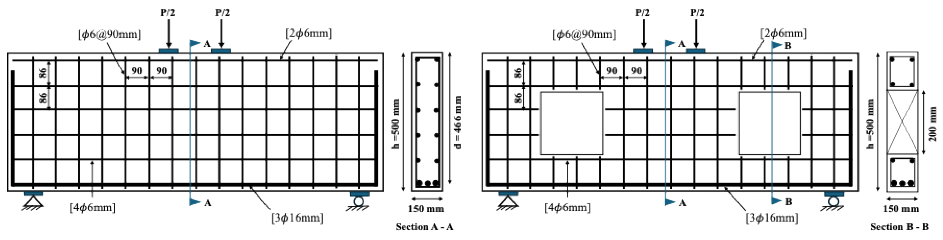
Figure 2.
Modeling of loading and boundary conditions.
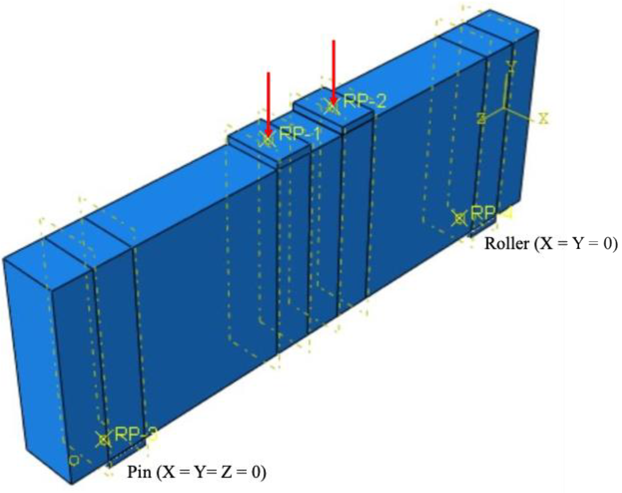
Figure 3.
Comparison of the experimental and numerical results.
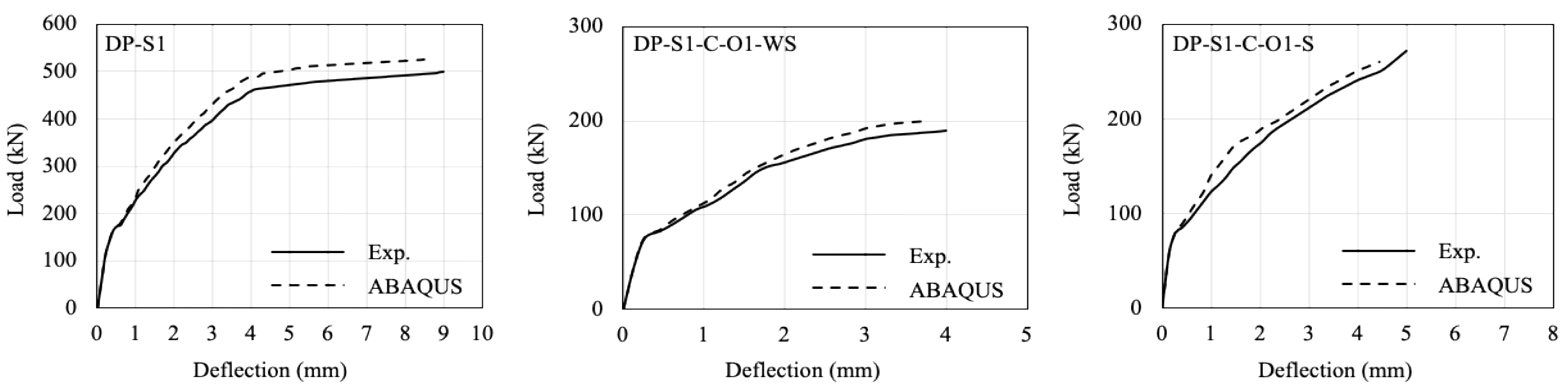
Figure 4.
Experimental vs. numerical failure patterns: a) DP-S11, b) DP-S1-C-O1-WS, and c) DP-S1-C-O1-S.
Figure 4.
Experimental vs. numerical failure patterns: a) DP-S11, b) DP-S1-C-O1-WS, and c) DP-S1-C-O1-S.
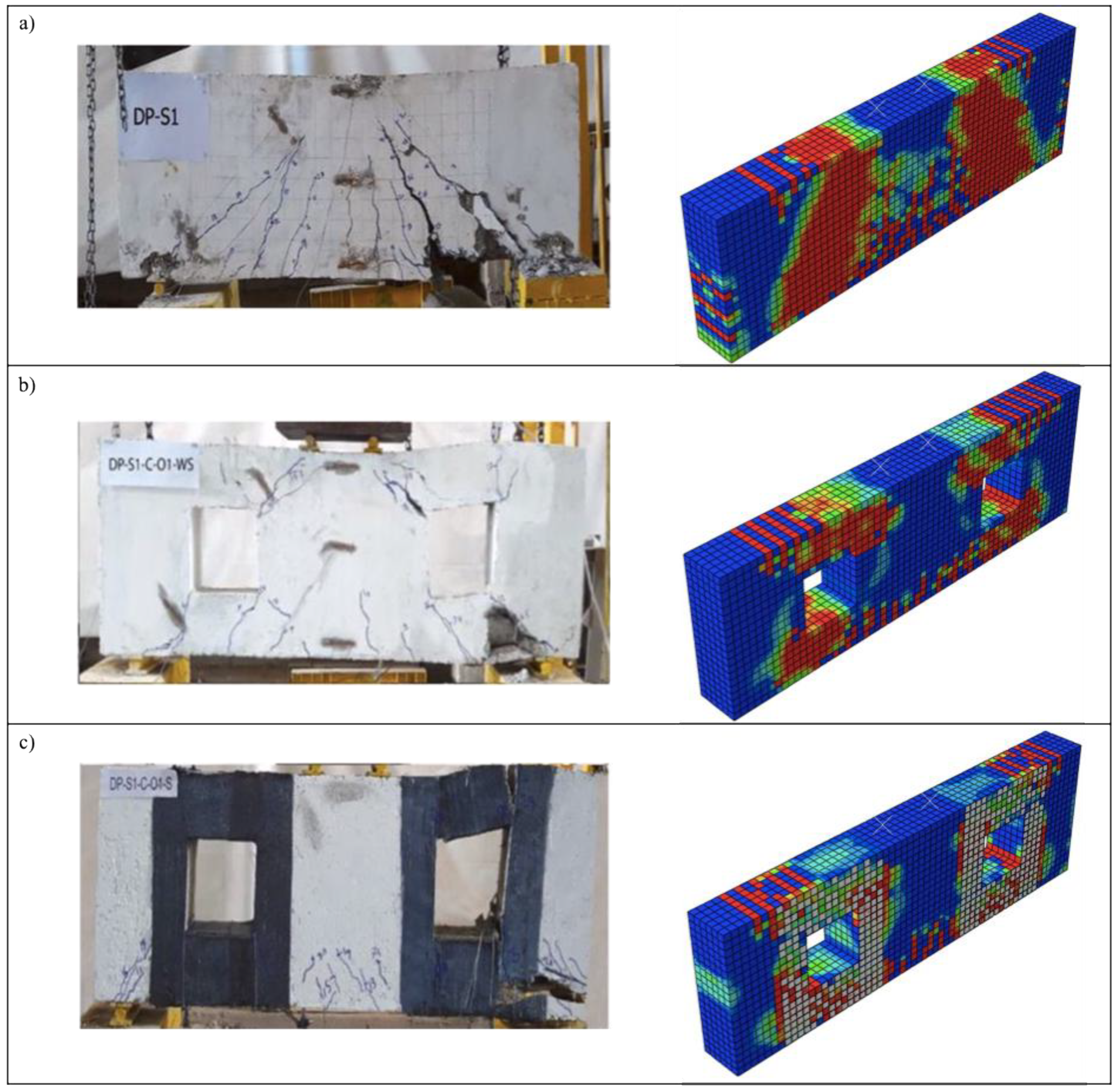
Figure 5.
Comparison of the numerical results: a) FEM of DP-S1-C-O1-WS with closed-end stirrup; b) FEM of DP-S1-C-O1-WS with open-ended stirrup.
Figure 5.
Comparison of the numerical results: a) FEM of DP-S1-C-O1-WS with closed-end stirrup; b) FEM of DP-S1-C-O1-WS with open-ended stirrup.
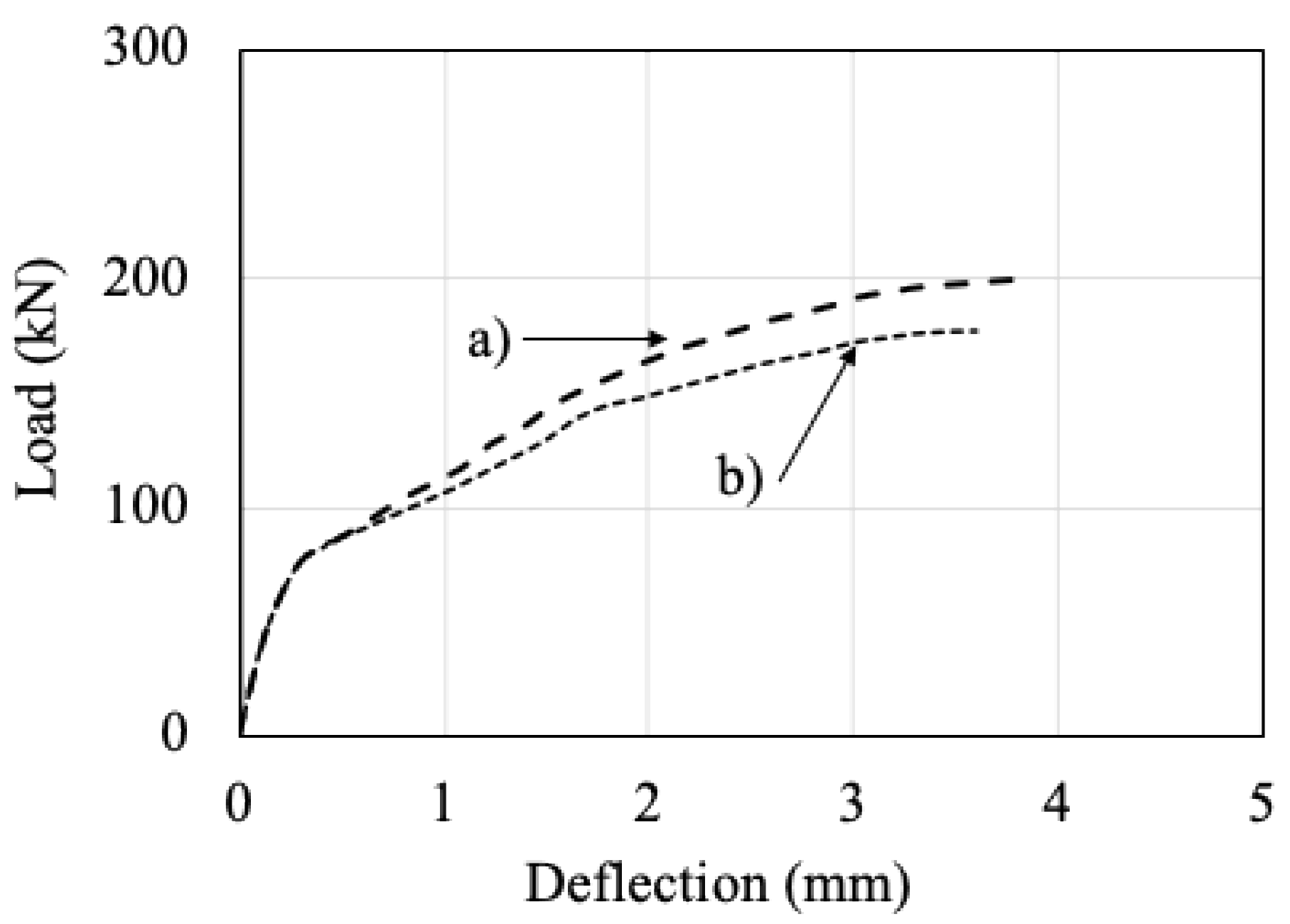
Figure 6.
Comparison of the numerical failure patterns: a) FEM of DP-S1-C-O1-WS with closed-end stirrup; b) FEM of DP-S1-C-O1-WS with open-ended stirrup.
Figure 6.
Comparison of the numerical failure patterns: a) FEM of DP-S1-C-O1-WS with closed-end stirrup; b) FEM of DP-S1-C-O1-WS with open-ended stirrup.
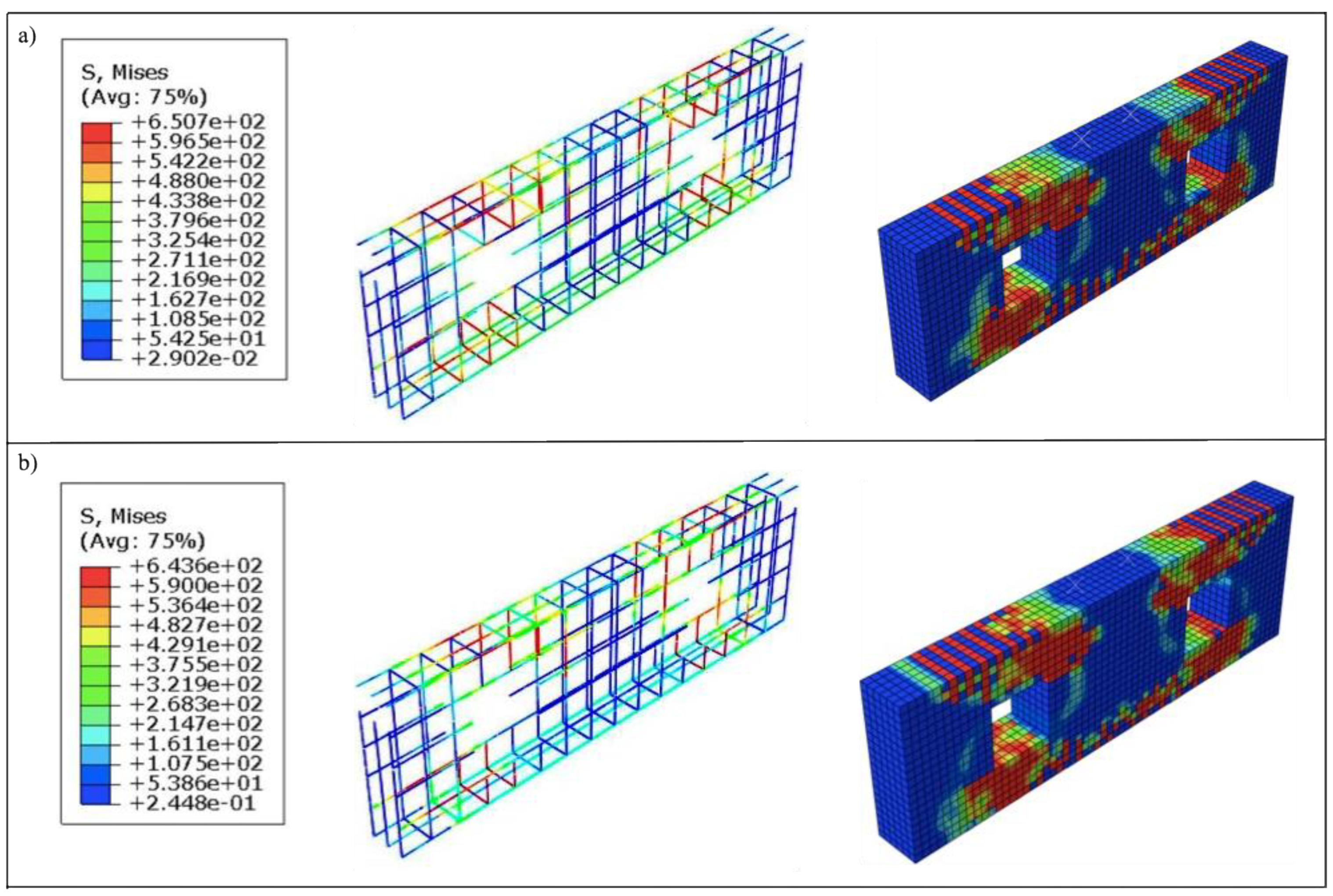
Figure 7.
Schematic of the locations and strengthening of web openings.
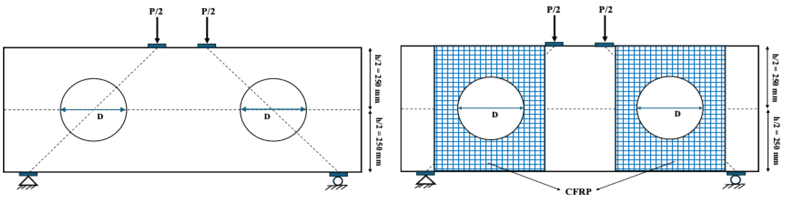
Figure 8.
Schematic showing the reinforcement bars that need to be cut to create the web openings.
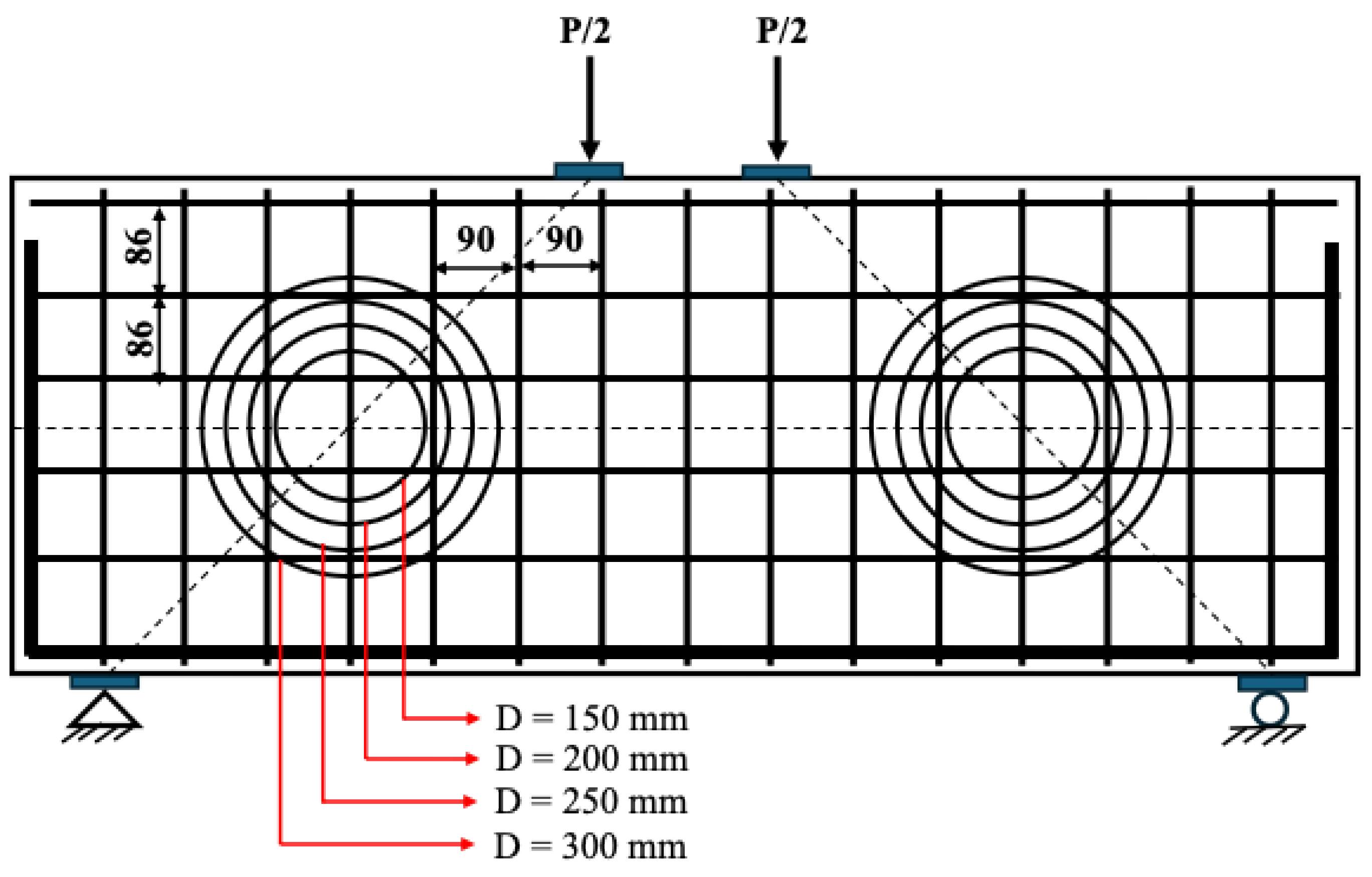
Figure 9.
Damage patterns for unstrengthened FEMs.
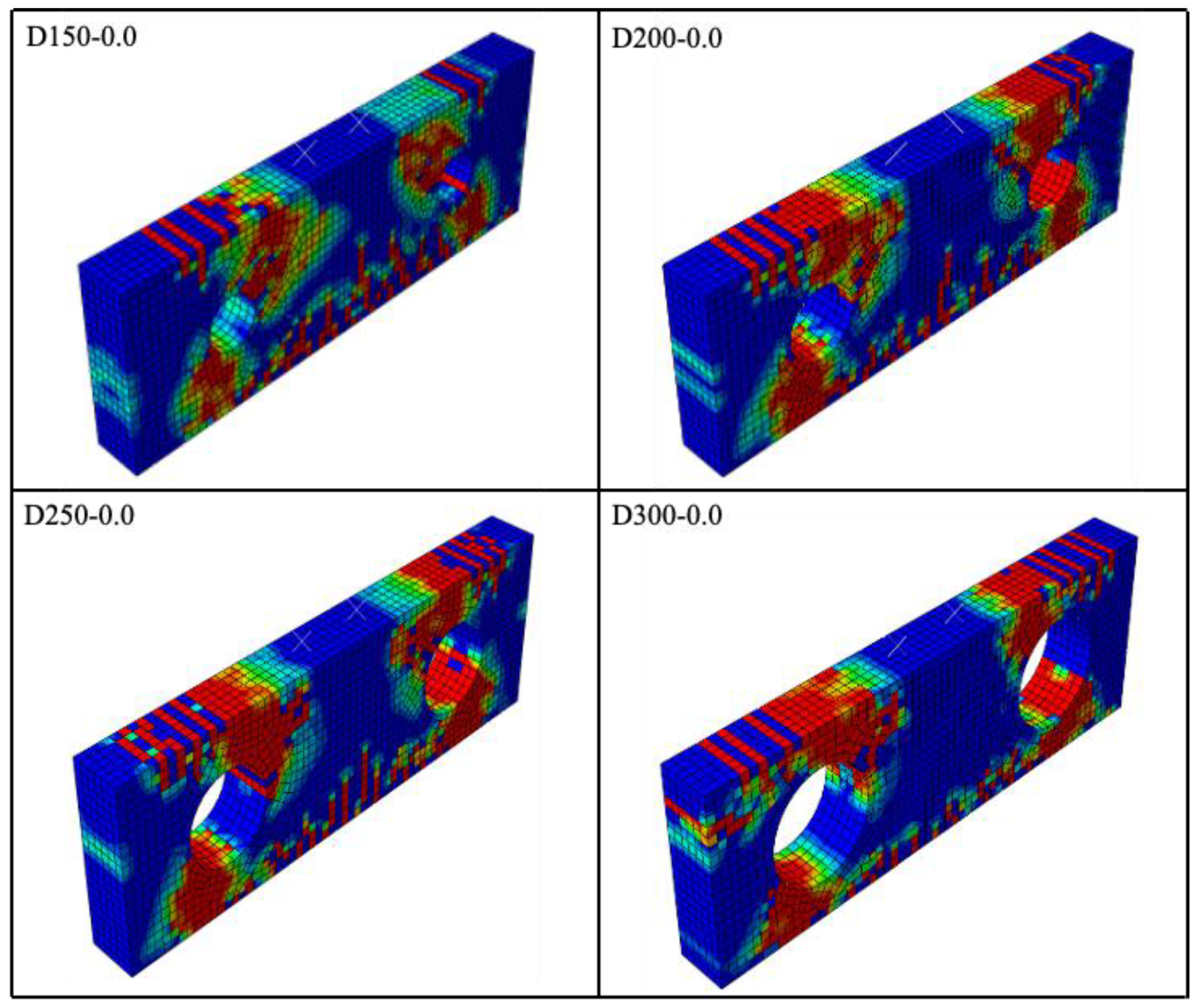
Figure 10.
Comparison of load-displacement curves for unstrengthened elements: a) DP-S_FEM, b) D150-0.0, c) D200-0.0, d) D250-0.0, e) D300-0.0.
Figure 10.
Comparison of load-displacement curves for unstrengthened elements: a) DP-S_FEM, b) D150-0.0, c) D200-0.0, d) D250-0.0, e) D300-0.0.

Figure 11.
Influence of the CFRP thickness on the load-displacement relationship.

Figure 12.
Influence of the CFRP thickness and web opening diameter on the load-carrying capacity and energy consumption capacity.
Figure 12.
Influence of the CFRP thickness and web opening diameter on the load-carrying capacity and energy consumption capacity.
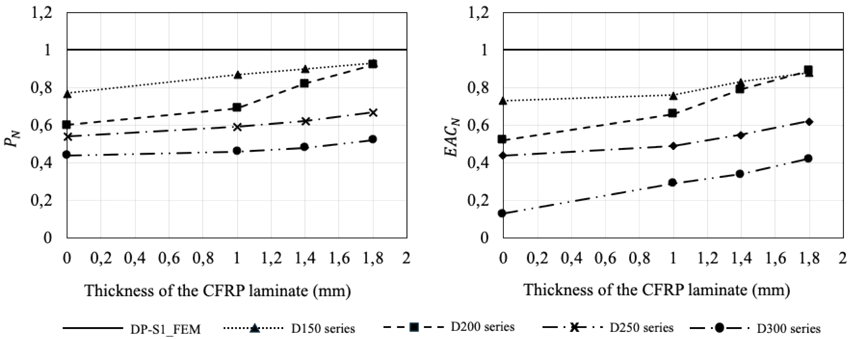

Table 1.
Mechanical properties of the reinforcements.
| Reinforcement | Measured Diameter (mm) |
Yield stress, (MPa) |
Ultimate stress, (MPa) |
Elongation (%) |
|---|---|---|---|---|
| ϕ6 | 5.5 | 623.96 | 685.5 | 8.5 |
| ϕ16 | 16 | 569.67 | 668.79 | 12.5 |
Table 2.
Concrete properties.
| (MPa) | (MPa) | Rupture stress, (MPa) |
Elastic modulus, (MPa) |
Poisson’s ratio |
|---|---|---|---|---|
| 27 | 3.1 | 3.5 | 24667 | 0.2 |
Table 3.
CDP parameters [29].
Table 3.
CDP parameters [29].
| Parameter | Elongation (%) |
|---|---|
| 36o | |
| 0.1 | |
| 0.16 | |
| 0.667 | |
| 0.00001 |
Table 4.
Results of the parametric study.
| Specimen | (kN) | (mm) | (kN) | (J) | |
|---|---|---|---|---|---|
| DP-S1-FEM | 525 | 8.50 | 1.00 | 3610.82 | 1.00 |
| D150-0.0 | 405 | 7.00 | 0.77 | 2634.78 | 0.73 |
| D150-1.0 | 460 | 8.27 | 0.87 | 2757.76 | 0.76 |
| D150-1.4 | 470 | 8.40 | 0.90 | 2981.59 | 0.83 |
| D150-1.8 | 488 | 8.45 | 0.93 | 3161.05 | 0.88 |
| D200-0.0 | 317 | 4.21 | 0.60 | 1895.68 | 0.52 |
| D200-1.0 | 365 | 8.20 | 0.69 | 2389.08 | 0.66 |
| D200-1.4 | 430 | 8.35 | 0.82 | 2857.94 | 0.79 |
| D200-1.8 | 485 | 8.42 | 0.92 | 3225.58 | 0.89 |
| D250-0.0 | 285 | 3.67 | 0.54 | 1573.67 | 0.44 |
| D250-1.0 | 310 | 7.29 | 0.59 | 1763.22 | 0.49 |
| D250-1.4 | 325 | 7.44 | 0.62 | 2001.79 | 0.55 |
| D250-1.8 | 351 | 7.49 | 0.67 | 2255.66 | 0.62 |
| D300-0.0 | 230 | 2.96 | 0.44 | 464.74 | 0.13 |
| D300-1.0 | 240 | 5.65 | 0.46 | 1053.21 | 0.29 |
| D300-1.4 | 252 | 6.00 | 0.48 | 1226.25 | 0.34 |
| D300-1.8 | 275 | 6.60 | 0.52 | 1530.71 | 0.42 |
Disclaimer/Publisher’s Note: The statements, opinions and data contained in all publications are solely those of the individual author(s) and contributor(s) and not of MDPI and/or the editor(s). MDPI and/or the editor(s) disclaim responsibility for any injury to people or property resulting from any ideas, methods, instructions or products referred to in the content. |
© 2025 by the authors. Licensee MDPI, Basel, Switzerland. This article is an open access article distributed under the terms and conditions of the Creative Commons Attribution (CC BY) license (http://creativecommons.org/licenses/by/4.0/).
Copyright: This open access article is published under a Creative Commons CC BY 4.0 license, which permit the free download, distribution, and reuse, provided that the author and preprint are cited in any reuse.


