
Submitted:
26 December 2025
Posted:
29 December 2025
You are already at the latest version
Abstract
The article considers issues related to improving the surface characteristics of titanium Gr2 using one of the lightest, cheapest and ecological methods - electrospark deposition (ESD) with low pulse energy and with ultradisperse electrodes TiB2-TiAl with nanosized additives of NbC and ZrO2. By means of profilometric, metallographic, XRD, SEM and EDS methods, the change in the geometric characteristics, composition, structure, micro- and nanohardness of the coatings as a function of the electrical parameters of the ESD regime has been studied. The results show that the use of TiB2-TiAl electrodes and low pulse energy allows the formation of dense, continuous and uniform coatings, demonstrating a significant reduction in roughness and inherent irregularities and structural defects of electrospark coatings, as well as the synthesis of newly formed wear-resistant phases and amorphous-nanocrystalline structures. The obtained coatings have crystal-line-amorphous structures, with newly formed intermetallic and wear-resistant phases with minimal defects, with roughness, thickness and microhardness, which can be controlled within the ranges Ra =1.8-3.5 µm, δ= 8-20 µm, HV=9-13 GPa, respectively. Energy pulse parameters have been defined to produce of coatings with a predetermined thickness and roughness, maximum increased hardness and with the most favorable characteristics in terms of abrasive and corrosion resistance.
Keywords:
local electric spark deposition (LESD)
; titanium
; roughness
; microhardness
; phase composition
; carbides
; borides
; nitrides
; amorphous
; nanostructures
1. Introduction
In recent years, due to their unique properties, titanium and its alloys have become increasingly attractive materials and are intensively used in almost all industrial sectors such as rocket and space technologies and aviation, shipbuilding, automotive, biomedical, energy, chemical and defense, household industries and many others [1,2,3]. However, the relatively low hardness of these alloys, their high chemical activity, their tendency to intense abrasive and adhesive wear and a variable coefficient of friction significantly limit and hinder their use in frictional units and mechanisms of machines [4,5,6] and many other applications. At the present stage, the main strategy for solving this problem is the use of surface modification methods, which are one of the cheapest and most effective ways to create surface layers with high mechanical and tribotechnical characteristics, combined with material economy, product cost reduction and the possibility of their repeated use. Due to the continuously growing interest in the industrial use of titanium alloys, improving their surface properties in order to expand their range of applications has become a current problem in titanium alloys research and an important research area worldwide. Researchers are constantly investigating and evaluating methods and coating materials to find the most suitable combinations between the properties of the coated surfaces and the most economical, safe and environmentally friendly methods used. Modern science and technology provide a variety of such methods [7,8,9,10,11,12], but the most popular of them, such as chemical and physical vapor deposition (CVD and PVD), galvanic, laser, electron beam, thermochemical deposition, ion-plasma nitriding, microarc oxidation and thermal spraying, cannot always meet all industrial requirements. They are not always applicable due to various limitations, such as their ability to process only certain materials, complex, energy-intensive and expensive equipment and technologies, high and excessive production costs, environmental pollution, unfavorable structural and thermal deformation of the base, as well as the inability to provide the necessary adhesion and thickness, or the necessary physicomechanical, tribological and corrosion properties of the coatings, their inability to produce modification of complex geometric contours, or the need for pre- and post-treatment of the coated surfaces.
In many cases, the application of most of the methods mentioned above, which are implemented through complex technologies and require high investments and costs, is not always economically viable and appropriate. Due to its simplicity and flexibility, electrospark deposition - ESD with its extremely low cost, easy and universal technology, simple, cheap, compact and portable equipment [13,14,15] has a number of advantages, allowing to overcome most of the limitations inherent in the above methods [16,17,18,19,20,21] and motivating its growing popularity, constantly expanding applications and its ever-widening distribution for surface strengthening of titanium surfaces. Its main advantages over the methods mentioned above noted by the authors are environmental safety; high efficiency at extremely low material and energy costs, universal and maximally simple technology, one of the strongest bonds of the coating with the substrate compared to other methods; low thermal effect and absence of heating and deformation of the laminated product; possibility of local processing of any surface, even of the most complex shape, leaving the rest of the surface untouched; ease of performing technological operations; rapid local heating and rapid cooling, which reduces the heat-affected zone and leads to the formation of surface layers with a fine-grained and even amorphous structure; possibility of applying a wide range of any electrically conductive materials and of changing the characteristics and properties of the coatings in a wide range through the energy parameters of the processing modes. Compared to laser ablation, CVD and PVD processes, thermal methods, ion-plasma nitriding, etc., the ESD method is much more economical and easier to implement and does not require vacuum chambers, complex and expensive equipment, as well as preliminary and subsequent treatments of the deposited surface.
The method is based on the process of electrical erosion in a gas environment and consists of transferring particles of the material from a coating electrode (anode) to the surface of the coated product (cathode) under the action of numerous short-term pulsed electric spark discharges, the duration of which is most often of the order of 10-6 – 10-5 s. According to data from many authors [13,14,16,17,21,22,23,24,25], the high intensity of the electric field - 107–109 W/cm2 (much higher than the critical intensity at which the electrodes melt), the pressure of the shock wave from the action of the electric spark, which reaches 2.106 - 7.106 MPa, and the high temperature of the electrode surface - 5.103 to 2.104 °C, cause explosive melting of microscopic particles of the electrode and partial local melting of microscopic areas of the substrate. The melted and evaporated from the electrode microparticles in mixed vapor, liquid and solid (softened) states accelerate in the discharge channel, and collide at high speed they collide with the surface of the locally melted microspot of the cathode and partially diffuse, forming a mixture of both materials and new compounds and phases resulting from their chemical interaction and from reactions with elements from the surrounding environment. The ratios between the phases transferred to the cathode and the size of the single portions of transferred anode material depend on the pulse energy and the type of anode and cathode materials. The extremely high cooling rate (105–106 °C/s) noted in the works [14,16,17,21,22,23,24,25] allows the formation of new ultradisperse, amorphous and nanoscale structures demonstrating unique tribological and corrosion efficiency.
Despite all its advantages, this method also has certain disadvantages that impede its further widespread adoption for improving the surface properties of titanium and its alloys and create a need for further research aimed at their removal. According to the cited researchers, these are the relatively small and uneven thickness of the coatings - most often from 5-6 to 40-50 µm, the relatively high roughness and unevenness of the surface, the presence of pores and cracks, residual tensile stresses and a decrease in fatigue strength in the surface layer, the difficulty of controlling the homogeneity of the coatings and the uniform distribution of the elements, as well as the relatively low productivity (2-6 min/cm2) and insufficient information on the choice of processing modes and electrode materials.
ESD on titanium and its alloys is most often performed at single pulse energies of 0.1-0.6 J, using a wide range of electrode materials - pure metals, alloys and mainly hardalloy compositions. In hardalloys electrodes, the presence of electrode material transferred from the solid phase is higher and the formed coatings usually have increased roughness compared to that of the base. Almost all authors report that increasing the thickness of the coatings is possible by increasing the pulse energy, but at the same time their roughness, unevenness and the amount of structural defects also increase, which adversely affects their tribological and corrosion characteristics. It is obvious that in order to obtain coatings with low roughness and fewer structural defects, it is necessary to use pulses with lower energy. However, in this case, the amount of transferred electrode material and the thickness of the coatings will have lower values. In response to this dilemma, a significant number of studies have emerged in recent years, focused on the development and use of electrode materials enabling the production of coatings with lower roughness and structural defects on titanium surfaces. Cadney et al. [23], Milligan et al. [24], Liu, et al. [26], Burkov et al. [27] use aluminum and aluminum alloys to obtain coatings with reduced roughness and structural defects and improved wear resistance, and coatings made of TiAl alloys [26,27] also demonstrated increased corrosion resistance. However, the metals and alloys used by the authors above do not provide sufficiently high hardness and wear resistance. In order to improve the characteristics and wear resistance of titanium surfaces, other researchers use various hard alloy compositions based on TiC and TiN -[28,29,30], WC-[22,31], TiB2 and ZrB2-[32,33,34,35] for electrodes. According to these authors, the hardness and wear resistance of titanium surfaces coated with hardalloy compositions significantly exceed of surfaces coated with metal alloys, but the increased roughness and structural defects of hard alloy coatings reduce the effect of their use and are unfavorable in terms of their corrosion resistance. As an alternative approach, the production of amorphous and nanostructured surfaces through ESD has emerged. The formation of amorphous-nanocrystalline and amorphous coatings by selecting appropriate electrodes and electrical parameters of the pulses is reported in references [16,17,21,22], as well as Cadney et al. [23], Milligan et al. [24], Burkov et al. [25], Xiang Hong et al. [28] E. A. Levashov et al. [30]. These and other authors report that the amorphous and nanostructured coatings they have obtained differ from those obtained with conventional electrodes in terms of improved physical and mechanical characteristics, with small structural defects, increased wear resistance and improved corrosion characteristics. Most of the electrodes used to form amorphous coatings, however, are made of various metal alloys, and despite the improved characteristics of the coatings, their hardness and wear resistance are usually lower than that of coatings obtained from hardalloys compositions. (For example, in the work [32] a 4-fold increase in the wear resistance of AlN–ZrB2 coatings is reported, in [33] with an electrode based on TiC-TiB2, a pulse voltage of 92 V and a frequency of 1500 Hz the authors report over 13 GPa microhardness of the coatings on Ti6Al4V, while with the metal electrodes used the microhardness of the coatings is most often up to 9-10 GPa). It is evident that the further enhancement of the ESD effect is associated with the development and use of more advanced electrode materials that ensure the production of coatings with a predominant amount of liquid phase transfer, the occurrence of exothermic chemical reactions in the interelectrode gap, strong adhesion to the titanium surfaces, higher microhardness and wear resistance combined with low roughness and minimal structural defects. A fundamentally new approach to the production of suitable electrodes was discovered with the development of high-temperature self-propagating synthesis (SHS) technology. By using SHS technology, the authors Levashov, Manakova, Zamulaeva, Kudryashov, et al. [30,31,36,37,38,39,40] created hardalloys electrodes from ultradisperse powders, dispersedly strengthened with nanosized additives and with them managed to achieve both higher microhardness and wear resistance than that of coatings obtained with metals and metal alloys, as well as a reduction in structural defects characteristic of hard alloy coatings. With these electrodes at relatively low pulse energy and pulse duration up to 60 µs, they produced multifunctional coatings with amorphous-nanocrystalline structures and a variety of unique properties, with higher physical, mechanical and tribotechnical properties, which increase the life of the coated surfaces by a factor of 2–5. These results outline a promising direction for improving the structure and properties of electrospark coatings. However, there is still no comprehensive data in the literature on the characteristics of these coatings on titanium surfaces.
In this context, the aim of this work is to investigate the possibility of using the ESD method on titanium with a TiB2-TiAl nano electrode created by SHS [37,38,39,40], by studying the relationships between the parameters of pulse discharges and the topography, composition and structure of the coated titanium surfaces and to define appropriate energy conditions for creating coatings with reduced roughness and structural defects and parallel local synthesis of new wear-resistant phases and amorphous-nanocrystalline structures with increased hardness, thus achieving further additional improvement of the operational properties of titanium surfaces.
2. Materials and Methods
2.1. Electrode Selection
An ultradisperse electrode, developed by self-propagating high temperature synthesis SHS with the composition TiB2-TiAl nano, (which will be called TiB2-TiAl for short), (74%Ti + 12%B + 14%Al) dispersedly reinforced with 7% nanosized ZrO2 and additives of NbC particles, created by the authors [37,38,39,40], was used to form coatings with amorphous and nanostructured phases and to increase the microhardness and wear resistance of the coated surfaces. In our previous works [41,42,43,44], the favorable influence of the TiB2-TiAl electrode on the composition and some properties of the coatings was established. Titanium borides (TiB, TiB2) have high physical and mechanical characteristics such as wear resistance, superhardness and low coefficient of thermal expansion, which makes them one of the most promising materials for use as a wear-resistant component of electrodes. High adhesion, hardness and wear resistance of hard alloy coatings based on TiB and TiB2 have been reported in [32,33,34,35]. However, the use of titanium borides is limited due to their high brittleness and resistance to electroerosion. This problem was solved by the authors [37,38,39,40] by adding a metallic binder TiAl, which leads to wetting of the wear-resistant solid phase. The intermetallic binary system Ti-Al has a low density, high strength and high temperature resistance and is designed to provide both high adhesion to the substrate and the formation of wear-resistant aluminum borides and oxides [23,24,25,26,27,30,38,39]. Nanosized additives have been introduced to act as modifiers in the coating formation process to improve the deposition process and coating quality, as well as to form a favorable combination of high hardness, oxidation resistance and low friction coefficient [38,39,40].
2.2. Substrate
Technical titanium Ti-Gr2 (AISI UNS R R56200 and R50400) was used as the substrate. In the initial studies for the initial selection of the parameters of the regimes, preliminary depositions were performed on sheet material with a thickness of 2 mm, and for the subsequent studies, plates with dimensions of 12x12x5 mm obtained by electrical discharge cutting (EDM) and subsequent grinding to a roughness Ra ≈ 2-2.5 μm were used.
2.3. Research Apparatus
In order to reduce the size of erosion craters on the substrate surface and obtain a smoother and more uniform layered surface with minimized surface defects, in this work a variation of the classical electrospark deposition contactless local electrospark deposition (LESD) [45] with low pulse energy – 0.005 to 0.045 J. was used, since this method produces dense and uniform coatings with low roughness and provides an acceptable combination of characteristics and properties suitable for simultaneously increasing wear resistance and corrosion resistance. The coatings were applied using a mechanized machine type “ELFA” - Figure 1 with a rotating electrode, automatic maintenance of the discharge distance and controlled deposition speed of 0.6 mm/s. The process control was implemented by changing the electrical parameters of the mode.
The studies were conducted with pre-optimized process parameters and pulse energy. Based on a comparison of the roughness, thickness and surface relief of the coatings deposited in 34 modes (Figure 2a) with different values of the pulse parameters in the range: (current = 11.2-24 A, Capacitance C=0.22-5 μF, Pulse duration Ti=5-20 μs and pulse frequency f= 5-20 kHz at pulse duty cycle 0.1. In the study, 5 modes were selected in the range of the lower limit of the pulse energy (pulse parameters), in which uniform coatings with a fine structure and a minimum thickness of ≈10 μm were obtained (Figure 2b); and upper limit - the maximum possible pulse energy (pulse parameters), which produce relatively uniform coatings with minimal irregularities and structural defects and with low transfer from the solid (softened) phase.
The pulse parameter values of the selected modes are shown in Table 1. The selected mode parameters are consistent with both our previous studies [41,42,43,44] and the data in the works [32,33,34,37,38,39,40] that use ESD technique with reduced pulse energy to prepare TiB–TiB2 coatings with uniform fine structure and higher heat resistance and wear resistance compared to coatings made of hardalloy electrodes based on titanium carbide. The coatings were deposited with three consecutive electrode passes.
2.4. Measurement Methodology.
Surface topography, microhardness, thickness, composition, structure and wear resistance were used as the main indicators to evaluate the properties of LESD modified titanium surfaces.
- The roughness parameters of the coatings (average roughness—Ra; root mean square rough-ness Rq; maximum profile height—Rt; the average value of the 5 highest protrusions and 5 deepest depressions of the profile within the basic length—Rz), were measured with the profilometer “AR-132B” (Shenzhen Graigar Technology, Co., Ltd., Shenzhen, China) according to the ISO 21920:2021 standard in two mutually perpendicular directions in five sections. The arithmetic average values, standard deviation and confidence interval were determined. The sharply different values were rejected using the Grubbs method.
- The thickness δ was measured with a dial indicator with an accuracy of 0.001 mm. The results are the arithmetic mean of 5 parallel measurements.
- Vickers microhardness (HV) was measured from above (on the top of the coating) after smoothing the surface irregularities. The hardness tester “Zwick 4350”- (Zwick Roell, GmbH & Co., KG, Ulm, Germany) equipped with a Vickers diamond prism indenter at a load of 0.2 N for a time of 10 s was used. The number of parallel measurements was 10. In order to eliminate the influence of the substrate, the measured hardness was calculated according to the method presented in [46].
- To obtain a more accurate assessment of the properties of the coatings, the universal hardness HU was also measured with a computer-controlled FISCHERSCOPE® H100 nanotester at a load of 300 mN with a Vickers diamond indenter and a penetration depth of 0.8-1.6 μm. The average values of the 10 measurements performed on each sample were taken.
- Microstructural, topographic morphological analyses and the distribution of elements of the coatings were performed with the metallographic optical microscope “Neophot 22” (Carl-Zeiss, Jena, Germany) and the scanning electron microscope (SEM-EDS) “EVO MA 10 Carl Zeiss” with a built-in X-ray energy-dispersive microanalyzer EDX system from “Bruker” (Bruker AXS, Karlsruhe, Germany).
- The phase composition was investigated with a Bruker D8 Advance X-ray diffractometer (Bruker AXS, Karlsruhe, Germany) in “Cu Kά” radiation.
3. Results and Discussion
This section may be divided by subheadings. It should provide a concise and precise description of the experimental results, their interpretation, as well as the experimental conclusions that can be drawn.
3.1. Coating Characterization – Roughness, Thickness δ, and Structure of Coatings
As can be seen from the profilometric results, the values of the roughness parameters of the coated samples are higher than those of the substrate and for the studied energy range vary within the limits of Ra = 1.8 – to 3.2 μm, and the thickness δ - from 9 to 19.5 μm. Within the range specified above, the roughness and thickness of the obtained coatings can be adjusted by the LESD modes. With an increase in energy (current I, capacitance C and pulse duration Ti) the roughness parameters and thickness of the coatings also increase, with their highest values being recorded for sample 1, i.e. at the highest used values of C, Ti and I (Figure 3a,b). The lowest roughness and thickness are recorded for sample 3, where the pulse energy is also the lowest. The strongest influence on the change in roughness and thickness of the coatings is exerted by the capacitance C and the duration of the pulses Ti, followed by the current I.
Figure 4 presents typical SEM images, at different magnifications, of the general view of the surface topography of the coated surfaces in the experimental modes, and Figure 5 shows the cross-sections of samples 1 and 4.
It is evident that the coatings form a structure with a specific relief on the titanium surface, formed mainly with the participation of the liquid phase. In this structure, the electroerosion craters and the smooth surface areas between them are distinguished, which are clearly visible at higher magnification (Figure 4, h,i,j,k,l). On the samples, convex areas (accumulations of incompletely melted electrode particles), glass-like smooth areas (Figure 4, h,i,j,k) and those formed by small particles with slight irregularities are distinguishable. It can be seen that the most uniform surface is the one of the coatings obtained at energy up to 0.015 J. In the coatings applied with the lowest pulse energy (lowest values of I, C, Ti) - (samples 2 and 3), the irregularities are smaller, the surface is smoother and more homogeneous, the structural elements that make them up are smaller in size, and microcracks are almost not detected. With increasing pulse energy (in the e-d-a direction - Figure 4 - samples 5,4,1 - Table 1) a gradual increase in the roughness and irregularities of the coatings is observed. At the highest used energy (I=16 A, С=4.4 µF and Ti=12 µs) – sample 1 - Figure 4a,k,l, the highest irregularities are observed, as well as single separate accumulations caused by the transfer of incompletely melted electrode particles, cavities and micropores clearly distinguishable in Figure 4g,k,l. At the next highest pulse energy sample 4 – the surface of the coating is more homogeneous and smooth, and micropores and irregularities are almost not observed (Figure 4,d,i). The inhomogeneous surface of the coatings is obvious. Within the same coating (Figure 4a,k,l) different areas with a predominant light or dark color are observed, which is expected considering the multicomponent composition of the electrode and the impossibility of its complete homogenization. The study also identified areas of defects such as pores and unmelted particles in the structure of the coatings, which are visible in Figure 4 g,l,k and Figure 5. Unmelted particles can adversely affect the adhesion of the coating and or serve as starting points for the development of microcracks and other defects. The topography of the coated surfaces is consistent with the data from the measurements of the roughness parameters and the thickness of the coatings – Figure 3, from which it is established that the highest values of the roughness parameters, as well as the thickness of the coatings up to 20 μm, were measured for sample 1 – Figure 3a and Figure 4a,k,l. In Figure 5, in cross-sections, the differences in the morphology of the coatings applied at the minimum and maximum pulse energy used can be seen.
From the microsection photographs it is seen that the layer differs from the substrate material in structure and grain size. Microscopic irregularities are observed in different places on the surface of the coatings. The interaction of the electrode and substrate melt leads to the formation of a transient interface layer tightly connected to the base, formed as a result of the diffusion penetration of the molten particles into the surface of the titanium base, their mixing with the titanium from the substrate and their rapid cooling, which suggests a strong metallurgical bond. In depth, this structure passes into the structure of the base material. While coatings applied at the minimum pulse energy used are dense and uniform, those applied at the maximum energy have almost twice the thickness (Figure 5b), but also more irregularities and the presence of rare cracks and cavities. Almost all researchers of the process explain the appearance of pores and irregularities as a result of surface tensile stresses, with the mechanical properties of the electrode material and the excessively high pulse energy used. With an increase in the pulse energy above certain limits, the proportion of the transferred material from brittle fracture increases sharply, which worsens the quality, uniformity, roughness and structural defects of the resulting coatings. In addition, the increased pulse energy leads to other negative effects such as overheating of the electrode, the appearance of a thermally affected sublayer, the appearance of cracks and defects in the coatings, from which it follows that in order to avoid the above-mentioned defects, the energy must be increased to certain limits, which, as shown by the data in the literature and those from our previous studies, are different and specific for each specific electrode material. Therefore, in order to obtain a dense layer without microcracks, it is necessary to maintain the level of pulse energy and the most influential and in this case pulse parameter - the capacitance C - below certain values. Based on the obtained data (Figure 2, Figure 3, Figure 4 and Figure 5) and the results of our previous studies [41,42,43,44] in the case of ESD with the TiB2-TiAl electrode, this level can be determined as C ≤ 2.2 µF. The SEM images shown in Figure 4 confirm that by ESD with the electrodes used and low pulse energy E= 0.013-0.025 J (samples 2-4, Table 1), the presence of microcracks and surface roughness are significantly reduced compared to those obtained in the works [28,29,32,33,34] in the case of ESD with a vibrating electrode. The TiB2-TiAl coatings obtained in this work have a smoother and more uniform surface than those obtained with classical hard alloy electrodes and indicate that by ESD it is possible to obtain smooth coatings almost without structural defects but with a smaller thickness.
3.2. Phase Composition and Microhardness of the Coatings
Figure 6 shows the diffractograms of LESD samples 2, 3 and 4, and Table 2 gives the phase composition of the coatings and the values of the angle 2θ at which the characteristic peaks of the corresponding phases are registered. The X-ray diffraction patterns of the coatings applied in the other selected modes – Table 1 are similar.
Since each of the registered characteristic peaks at a specific angle 2θ corresponds to several different phases, the table lists all available phases registered in the presence of at least three diffraction peaks.
As can be seen from Figure 6, the X-ray diffraction patterns of the coatings are similar and their phase composition is close. The main differences are in the intensity and width of the characteristic peaks of the phases. In all coatings, the main phases of the electrode TiB2, TiAl are observed, but new compounds are also registered that are not present in the electrode and substrate such as Ti3.2B1.6N2.4, TiB, TiN, TiN0.3, Ti (CN), TiC1-x. Moreover, the amount of TiB2 is much less than in the hard alloy electrode material, which indicates its dissociation (or transformation). Small amounts of Al2O3, TiC0.3N0.7, TiC1-x, Ti6O, Ti2O and traces of Ti3O, AlN, AlB, BN, Al2.86O3.45N0.55 are also observed. Each new phase has its own unique properties that directly affect the microstructure and properties of the coating. XRD results show that in the LESD process TiB2 is partially decomposed to TiB and Ti, and the formed titanium nitrides, carbides, oxides and sets of phases with a general composition Ti (N,C) are due to the reactions of both titanium from the electrode and that from the base with nitrogen, oxygen and carbon from the surrounding air. The short contact time of the particles with oxygen from the environment creates favorable conditions for minimizing oxides in the coating. Increasing the pulse energy leads to an increase in the amount of transferred material, an increase in the degree of partial decomposition of TiB2 and, accordingly, an increase in the amount of high-hard and newly formed phases and the degree of alloying of the layer, as well as that of titanium oxides, the amount of which in samples 1 and 5 reaches about 5-5.8 %. The structural maxima also broaden and shift relative to those of the substrate, which is most pronounced in the coatings in sample 4 - Table 1 (I16 A, C=2.2 µF, Ti= 12 µs, f=8.33 kHz) and is an indicator not only of the presence of internal stresses and solid solutions, but also of the refinement of the structure until reaching an amorphous state. The high cooling rate, which according to the authors [15,17,22,23,24,25,26] reaches 105–106 °C/s, undoubtedly allows the formation of amorphous phases on the substrate surface. Due to the lower pulse energy used in this work and the much shorter pulse duration of 8 and 12 µs, the transferred portions of molten electrode material are much smaller, the sizes of the molten cathode spot are also much smaller, which creates prerequisites for a higher cooling rate and with a high degree of probability it can be expected that coatings with a fine structure, nanocrystalline and more amorphous structures will be formed on the cathode than when using conventional hard alloy electrodes and the usual higher pulse energy and pulse duration used in the ESD process. The presence of “glass-like” zones (Figure 4,h,I,j,k) ) also indicates the occurrence of a certain partial “amorphization” of the coating. At higher pulse energy - samples 1 and 5 - (С=4.4 µF), the size and volume of the cathode spot increase, and the cooling rate of the melt decreases and, accordingly, the amount of glassy amorphous-nanocrystalline zones also decreases. However, the presence of peaks in the extended angular zones also suggests the presence of crystals. Table 3 shows the range of variation of the crystallite sizes of the main registered phases in the five modes used for LESD. As can be seen from the table, the crystallite sizes calculated by the Scherer formula for the different phases and modes are in the range of 6-87 nm, which indicates the presence of nanosized crystal structures in the layer and gives reason to conclude that with the studied TiB2-TiAl electrodes, coatings with an amorphous - nanocrystalline structure - metal nanosized - partially amorphous matrix, in which nanosized high-hard wear-resistant particles are embedded, were formed by LESD. The comparison of the phase composition of the coatings deposited with the experimental modes shows that in LESD with mode 4 the number and complex amount of carbide, nitride, boride and intermetallic phases are higher.
As can be seen from Figure 6, for the coatings obtained with a pulse energy of 0.025 J (sample 4 – I=16A, C=2.2 µF, Ti=12 µs), the broadening of the characteristic peaks at angles 2θ≈ 35-400 , 43-460 , 53-560 ,61-650 , 70-750 is the largest, therefore it can be expected that this coating has more amorphous phases than the other coatings. In the coatings obtained with this mode, the number and amount of high-hard phases and intermetallic compounds, the degree of amorphization and the surface hardness are higher than those of the coatings obtained with the other modes. Apparently, the pulse energy of 0.01-0.025 J at a capacity of C≤2.2 µF and Ti = 8 and 12 µs creates smaller sizes of the spot of the molten cathode and, consequently, a sufficiently high cooling rate of the mixed melt and obtaining coatings with an increased amount of amorphous phases, with reduced roughness, increased density and uniformity. Due to the presence of an amorphous-nanocrystalline structure and a reduced amount of structural defects, such as voids, irregularities and micropores, TiB2-TiAl coatings deposited in the used modes suggest a higher level of mechanical properties, exceeding the level of properties achieved on crystalline alloys currently used. Amorphous and nanostructured surfaces can be created in various ways - by hot isostatic pressing, SHS technology, laser, electron beam, CVD, PVD technologies, plasma thermal spraying, etc., but all of them require expensive equipment and high costs, which are not always economically viable. Due to its low cost and easy technology, the LESD process emerges as the technically and economically most advantageous alternative to the above methods for creating amorphous and nanoscale surfaces.
Figure 7 presents the elemental composition of the substrate, and Figure 8 shows the distribution of elements on a surface coated in mode 4 with high pulse energy - Table 1 in two different zones, marked on the SEM images with a green cross and the distribution map Figure 8c. As can be seen from the SEM images, Zone 1 is located in a low part (a recess) of the coating, and Zone 2 is localized on the surface of the accumulation caused by transferred incompletely melted electrode material. In both zones of the coating, the presence of the main elements of the electrode and the substrate, as well as the elements of the surrounding air environment N, O and C, was recorded. In all coatings, Ti from the substrate prevails (Figure 8). With increasing pulse energy, the amount of elements from the electrode material also increases at the expense of decreasing the amount of Ti (Figure 8 and Figure 9,a,b). As can be expected - the maximum amount of elements from the electrode is recorded in the coatings at the samples with the highest pulse energy 1,4,5 - Table 1. Oxygen is detected in the coatings, which is an indicator of oxidation in the process of spark discharges.
The comparison of the distribution in the two zones shows more than twice the amount of Al and B in zone 2, and a lower amount of Ti and N, which indicates a higher presence of electrode material. The carbon and oxygen content also differ, but the differences are relatively small. The higher amount of O2 in zone 2 indicates that in the transfer process the electrode material is oxidized to a greater extent than the cathode. The observed differences in the content of the elements prevent an accurate assessment of the distribution, as well as an accurate assessment of the differences in the content of individual elements in the composition of the samples coated in the different studied modes. The clearly expressed heterogeneity of the coating is confirmed by the distribution map – Figure 8 c. With such a variation in the composition, it can be expected that the mechanical properties will also vary. The presence of oxygen, nitrogen, carbon and boron in the composition of the samples confirms the data from the X-ray structural analysis and testifies to the formation of new phases in the LESD process - such as titanium and aluminum nitrides, carbides and oxides. Moreover, the distribution of oxygen repeats the distribution of both titanium and aluminum, which confirms the presence of titanium and aluminum oxides. However, the distribution of N and C repeats only that of Ti, which suggests the presence of titanium carbides, nitrides and carbonitrides. The data from the EDX mapping of the other studied samples are similar, with the difference that at higher energy parameters of the pulses the content of Al, O, N, C is also relatively higher, which corresponds to the larger portions of anodic material transferred to the cathode, but the heterogeneity of the coatings does not allow for an exact comparison. As can be seen from Figure 9 – EDX data for Sample 5, which was obtained at higher values of capacitance, but lower current I and pulse duration Ti, are similar, and the content of N, O, C, Al – Figure 9 b in areas with a structure similar to that of Figure 8 b is also similar.
Figure 10 shows the average values, as well as the minimum and maximum measured values of the microhardness HV, of the Universal nanohardness HU of the studied samples. For comparison, the values of the hardness and thickness of the coatings from the classical WC-Co8 electrodes, deposited in sample 4, are also given – Table 1.
From Figure 10 it can be seen that after LESD the average microhardness HV of the coatings significantly increases compared to that of the base 3.22 GPa and for the different modes is in the range 10.6 – 13.5 GPa, and the universal hardness HU – respectively in the range 9.2 - 11.6 GPa, exceeding that of the titanium substrate by a factor of 3 to 4.5. The microhardness obtained in the individual measurements varies in a very wide range (the lowest measured value is 7 GPa, and the highest 17.7 GPa), but the average values for the studied coatings are relatively close and are slightly higher, but comparable to the hardnesses obtained for the coatings from the WC-Co8 electrode in sample 4. The large differences in the individual measured values of micro- and nanohardness within the same coating are characteristic of ESD with composite electrodes and can be explained by the presence of the lower-hard plasticizing TiAl phase, the hard boride, carbide and nitride phases, the change in the initial chemical composition, the partial combustion of boron in the transfer process, the oxidation and dissociation of TiB2 and the formation of new phases with different hardness, as well as the uneven distribution of the high-hard phases in the layer, the presence of pores and inhomogeneity in the structure of the applied coatings and the influence of the base of soft titanium alloy on hardness. However, the higher content of the high-hard phases also determines the higher obtained hardness values, i.e. the observed trend is towards an increase in microhardness with increasing pulse energy, but a clear and unambiguous dependence and a correct assessment which does allow to establish of the influence of the pulse energy on microhardness on the pulse energy is not established.
An approximative comparison of the influence of the pulse energy and pulse parameters shows that the highest hardness HV and HU are demonstrated by the coatings deposited in mode 4 - (Sample 4), followed by those in mode 1 (Sample 1) – Table 1, whose composition is richest in high-hardness phases. The higher average and maximum values of HV and HU in sample 4 are obviously due to the better cohesive strength, the greater amount of amorphous-nanocrystalline structures and the relatively lower porosity of these coatings. The lowest values of HV and HU are observed in LESD with mode 5 (Sample 5), probably due to the greater amount of structural defects in this mode. In general, the differences in the average values of HV and HU of the studied samples are in a relatively narrow range up to ≈ 2.5 GPa. Moreover, the values of HV are slightly higher than those of the universal hardness HU, but the ratios between them are proportional. The metal bond as part of the coating material reduces the hardness of the coatings, but can provide high adhesion to the substrate and to serves as a matrix that firmly holds the particles of borides, carbides and nitrides and prevents their chipping off under load. A large scatter in the values of НV and HU is reported by almost all researchers. Our results are similar to those in most studies [17,18,19,25,28,33,34,35,37,38,39], where the microhardness of coatings from different electrode materials is most often reported at 8-12 GPa. The measured in this work microhardness values slightly exceed those obtained with conventional hard electrodes WC-Co8 - Figure 10, and those based on TiB2 obtained in the works [33,34,35], but the differences are relatively small and reach only ≈ 1.5 – 2 GPa.
The data obtained from these studies allow us to determine the range of pulse energy and pulse parameters, in which the amount of high-hardness compounds of the electrode material and the formed new carbides, borides, intermetallic compounds and amorphous-crystalline structures, as well as the geometric characteristics of the coatings, are combined in a compromise way. In the specified range, the most favorable from the point of view of the composition, structure and thickness of the coatings is mode 4 (Sample 4), and in terms of the roughness parameters and structural defects of the coatings - mode 3 (Sample 3). The summary of the results obtained shows that the use of a TiB2-TiAl electrode and contactless electrospark deposition LESD with pulse energy up to 0.025 J allows the creation of coatings from a predominantly liquid phase with better uniformity, lower roughness and porosity and higher microhardness compared to coatings obtained with conventional hard alloys and electrodes known in the literature.
4. Conclusions
By LESD with ultradisperse TiB2-TiAl electrodes and using low-energy pulses in the range I=11.2-16 A, C=0.5-2.2 µF, Ti=8-12 µs, dense and uniform coatings can be obtained with reduced roughness, minimal structural defects and with thickness, roughness and microhardness, that can be controlled through the energy parameters of the LESD mode in the ranges δ=9-20 µm, Ra=1.8-3.5 µm and HV = 9-13.5 GPa, respectively.
The results show that at a relatively low capacitance of up to 2.2 µF and pulses of 12 µs, a continuous and uniform layer with fewer defects and cracks with a thickness of up to 20 µm can be obtained.
The micro- and nanohardness of the coatings is 3-4.5 times higher than that of the titanium base, with the differences in the values of the coatings deposited in the used modes varying in the range of 1.5 -2.5 GPa. The highest microhardness is in LESD with a pulse energy of 0.025 J and pulse parameters I=16A, C=2.2 µF, Ti=12µs.
During the LESD process, a large number of newly formed wear-resistant phases and intermetallic compounds are synthesized in the coatings, as well as an increased amount of amorphous-nanocrystalline structures, improved micro- and nanohardness. The largest amount of amorphous-nanocrystalline regions is registered in the coatings in the mode with pulse energy E=0.025 J and current values I=16 A, capacitance C=2.2 µF, pulse duration Ti=12 µs and pulse frequency f= 8.33 kHz.
Based on the results of experimental studies, it can be stated that by using TiB2-TiAl electrodes by the LESD method with low pulse energy, it was achieved to obtain coatings with reduced surface defects, with improved topography, morphology, composition and structure, increased hardness as a result of obtaining new compounds and amorphous-crystalline structures and significantly improved quality of titanium surfaces. The results of the present study confirm the positive effect of coatings from TiB2-TiAl electrodes on the geometric characteristics, microhardness, composition and structure of coated titanium surfaces.
The obtained results create opportunities for preliminary selection of LESD modes to obtain coatings with the desired thickness, composition and roughness structure, to optimize the quality of the surface in order to create prerequisites for obtaining maximum triboeffect and increasing the operational properties corresponding to the type and requirements for the coated titanium surface.
In order to establish the influence of the improved characteristics of the coatings on their tribological and corrosion properties, it is necessary to conduct additional studies.
Author Contributions
Conceptualization, G.K., and T.P.; methodology, T.P., Y.S., V.M., A.N., K.P., and G.K.; validation, V.M., K.P., and A.N.; formal analysis, Y.S., B.T., and T.G.; investigation, V.M., Y.S., R.D., and K.P.; resources, A.N., K.P. and V.M.; data curation, R.M., Y.S., and B.T.; writing—original draft preparation, T.P., and V.M.; writing—review and editing, G.K. and R.D.; visualization, G.K., T.P., and K.P.; supervision, Y.S.; project administration, Y.S. All authors have read and agreed to the published version of the manuscript.
Funding
This work was accomplished with financial support from the European Regional Development Fund within the Operational Programme “Bulgarian national recovery and resilience plan”, procedure for direct provision of grants “Establishing of a network of research higher education institutions in Bulgaria”, and under Project BG-RRP-2.004-0005 “Improving the research capacity anD quality to achieve intErnAtional recognition and reSilience of TU-Sofia (IDEAS)”. The equipment for this study was funded by the European Regional Development Fund under “Research Innovation and Digitization for Smart Transformation” program 2021–2027 under the Project BG16RFPR002-1.014-0006 “National Centre of Excellence Mechatronics and Clean Technologies”.
Conflicts of Interest
The authors declare no conflicts of interest.
References
- Tomashov, N.D. Titanium and corrosion-resistant alloys based on it; Publisher: Metallurgy, Russia, 1985. (in Russian) [Google Scholar]
- Leyens, Ch.; Peters, M. Titanium and Titanium Alloys: Fundamentals and Applications; Wiley-VCH Verlag GmbH & Co. KGaA, 2003. [Google Scholar] [CrossRef]
- Gorynin, I.V.; Chechulin, B.B. Titanium in mechanical engineering; Publisher: Mashinostroenie, Moscow, 1990; in Russian. [Google Scholar]
- Gupta, M.K.; Etri, H.E.; Korkmaz, M.E.; et al. Tribological and Surface Morphological Characteristics of Titanium Alloys: a review. Archiv Civ. Mech. Eng. 2022, 22(72). [Google Scholar] [CrossRef]
- Philip, J.T.; Mathew, J.; Kuriachen, B. Tribology of Ti6Al4V: A review. Friction 2019, 7, 497–536. [Google Scholar] [CrossRef]
- Dong, H. Tribological properties of titanium-based alloys. In Surface Engineering of Light Alloys; Woodhead Publishing Series in Metals and Surface Engineering: Cambridge, UK, 2010; pp. 58–80. [Google Scholar] [CrossRef]
- Garbacz, H.; Wiecinski, P.; Ossowski, M.; Ortore, G.; Wierzcho´n, T.; Kurzydłowski, K.J. Surface engineering techniques used for improving the mechanical and tribological properties of the Ti6A14V alloy. Surface & Coating Technology 2008, 202, 2453–2457. [Google Scholar] [CrossRef]
- Zhang, L.-C.; Chen, L.-Y.; Wang, L. Surface Modification of Titanium and Titanium Alloys: Technologies, Developments, and Future Interests. Advanced Engineering Materials 2020, 22(5), 2070017, 1–37. [Google Scholar] [CrossRef]
- Grabarczyk, J.; Batory, D.; Kaczorowski, W.; Pązik, B.; Januszewicz, B.; Burnat, B.; Czerniak-Reczulska, M.; Makówka, M.; Niedzielski, P. Comparison of Different Thermo-Chemical Treatments Methods of Ti-6Al-4V Alloy in Terms of Tribological and Corrosion Properties. Materials 2020, 13(22), 5192. [Google Scholar] [CrossRef]
- Münz, W.-D.; Lewis, D.B.; Hovsepian, P.E.; Schonjahn, C.; Ehiasarian, A.; Smith, I.J. Industrial scale manufactured superlattice hard PVD coatings. Surf. Eng. 2001, 17(1), 15–27. [Google Scholar] [CrossRef]
- Nartita, R.; Ionita, D.; Demetrescu, I. Sustainable Coatings on Metallic Alloys as a Nowadays Challenge. Sustainability 2021, 13, 10217. [Google Scholar] [CrossRef]
- Martini, C.; Ceschini, L. A Comparative Study of the Tribological Behaviour of PVD coatings on the Ti–6Al–4V Alloy. Tribology International 2011, 44, 297–308. [Google Scholar] [CrossRef]
- Vizureanu, Petrică; Perju, Manuela-Cristina; Achiţei, Dragoş-Cristian; Nejneru, Carmen. Advanced Electro-Spark Deposition Process on Metallic Alloys. In Advanced Surface Engineering Research; Chowdhury, Mohammad Asaduzzaman, Ed.; IntechOpen: Publisher, 2018. [Google Scholar]
- Zhengchuan, Zh.; Guanjun, L.; Konoplianchenko, I.E. : A Review of the Electro-Spark Deposition Technology. Bull. Sumy Nat Agr Univ. Ser.: Mechanization and Automation of Production Processes 2022, 2(44), 45–53. [Google Scholar] [CrossRef]
- Barile, C.; Casavola, C.; Pappalettera, G.; Renna; Pappalettera, G.; Giovanni. Advancements in electrospark deposition (ESD) technique: A short review. Coatings. 2022, 12(10), 1536. [Google Scholar] [CrossRef]
- Zhang, Y.; Li, L.; Chang, Q. Research status and prospect of electro-spark deposition technology. Surf. Technol. 2021, 50, 150–161. [Google Scholar]
- Wang, J.; Zhang, M.; Dai, S.; Zhu, L. Research Progress in Electrospark Deposition Coatings on Titanium Alloy Surfaces: A Short Review. Coatings. 2023, 13, 1473. [Google Scholar] [CrossRef]
- Mikhailov, V.V.; Gitlevich, A.; Verkhoturov, A.; Mikhaylyuk, A. Electrospark alloying of titanium and its alloys, physical and technological aspects and the possibility of practical use. Short review. Surf. Eng. Appl. Electrochem. 2013, 49(5), 373–395. [Google Scholar] [CrossRef]
- Podchernyaeva, I.; Juga, A.I.; Berezanskaya, V.I. Properties of electrospark coatings on titanium alloy. Key Eng. Mater. 1997, 132, 1507–1510. [Google Scholar] [CrossRef]
- Penyashki, T.G.; Kamburov, V.V.; Kostadinov, G.D.; Kandeva, M.K.; Dimitrova, R. Possibilities and prospects for improving the tribological properties of titanium and its alloys by electrospark deposition. Surf. Eng. Appl. Electrochem. 2022, 58(2), 135–146. [Google Scholar] [CrossRef]
- Mulin, Y.I.; Verkhoturov, A.D.; Vlasenko, V.D. Electrospark alloying of surfaces of titanium alloys. Perspect. Mater. 2006, 1, 79–85. [Google Scholar]
- Tarelnyk, V.B.; Paustovskii, A.V.; Tkachenko, Y.G.; Konoplianchenko, E.V.; Martsynkovskyi, V.S.; Antoszewski, B. Electrode Materials for Composite and Multilayer Electrospark-Deposited Coatings from Ni–Cr and WC–Co Alloys and Metals. Powder Metall. Met. Ceram. 2017, 55, 585–595. [Google Scholar] [CrossRef]
- Cadney, S.; Goodall, G.; Kim, G.; Moran, A.; Brochu, M. The transformation of an Al based crystalline electrode material to an amorphous deposit via the electrospark welding process. J. Alloys Compd. 2009, 476, 147–151. [Google Scholar] [CrossRef]
- Milligan, J.; Heard, D.W.; Brochu, M. Formation of nanostructured weldments in the Al-Si system using electrospark welding. Appl. Surf. Sci. 2010, 256, 4009–4016. [Google Scholar] [CrossRef]
- Burkov, A.A. The effect of discharge pulse energy in electrospark deposition of amorphous coatings. Prot. Met. Phys. Chem. Surf. 2022, 58, 1018–1027. [Google Scholar] [CrossRef]
- Liu, Y.; Wang, D.; Deng, C.; Huo, L.; Wang, L.; Fang, R. Novel method to fabricate Ti–Al intermetallic compound coatings onTi–6Al–4V alloy by combined ultrasonic impact treatment and electrospark deposition. J. Alloys Compd. Interdiscip. J. Mater. Sci.Solid–State Chem. Phys. 2015, 628, 208–212. [Google Scholar]
- Burkov, A.A.; Chigrin, P.G. Synthesis of Ti–Al intermetallic coatings via electro spark deposition in a mixture of Ti and Al granules technique. Surf. Coat. Technol. 2020, 387, 125550. [Google Scholar] [CrossRef]
- Hong, X.; Feng, K.; Tan, Y.F.; Wang, X.; Tan, H. Effects of process parameters on microstructure and wear resistance of TiN coatings deposited on TC11 titanium alloy by electro spark deposition. Trans. Nonferrous Met. Soc. China 2017, 27, 1767–1776. [Google Scholar] [CrossRef]
- Podchernyaeva, I.A.; Lavrenko, V.A.; Berezanskaya, V.I.; Smirnov, V.P. Electrospark alloying of the titanium alloy VT6 with tungsten–free hard alloys. Powder Metall. Met. Ceram. 1996, 35, 588–591. [Google Scholar] [CrossRef]
- Levashov, Е.А.; Kudryashov, A.E.; Pogozhev, Yu.S.; Vakaev, P.V.; Zamulaeva, Е.I.; Sviridova, Т. А. Specific features of formation of nanostructured electrospark protective coatings on the OT4-1 titanium alloy with the use of electrode materials of the TiC-Ti3AlC2 system disperse-strengthe ned by nanoparticles. Russian Journal of Non-FerrousMetals 2007, 48(5), 362–372. [Google Scholar] [CrossRef]
- Levashov, Е.А.; Zamulaeva, Е.I.; A.E. Kudryashov, A.E.; Vakaev, P.V. Materials science and technological aspects of electrospark deposition of nanostructured WC-Co coatings onto titanium substrates. Plasma Processes and Polymers 2007, 4(3), 293–300. [Google Scholar] [CrossRef]
- Teplenko, M.A.; Podchernyaeva, I.A.; Panasyuk, A.D. Structure and wear resistance of coatings on titanium alloy and steels obtained by electro spark alloying with AlN–ZrB2 material. Powder Metall. Met. Ceram. 2002, 41, 154–161. [Google Scholar] [CrossRef]
- Gökçe, Mesut; Kayali, Yusuf; Talaş, Şükrü. The Ceramic Composite Coating (TiC+TiB2) by ESD on Ti6AL4V Alloy and Its Characterization. Ceramic Sciences and Engineering 2020, 3(1). [Google Scholar] [CrossRef]
- Shafyei, H.; Salehi, M.; Bahrami, A. Fabrication, microstructural characterization and mechanical properties evaluation of Ti/TiB/TiB2 composite coatings deposited on Ti6Al4V alloy by electro–spark deposition method. Ceram. Int. 2020, 46(10), 15276–15284. [Google Scholar] [CrossRef]
- Kovacik, J.; Baksa, P.; Emmer, S. Electro spark deposition of TiB2 layers on Ti6A14V alloy. Acta Metallurgica Slovaca 2016, 22(1), 52–59. [Google Scholar] [CrossRef]
- Manakova, O.S.; Kudryashov, A.E.; Levashov, E.A. On the application of dispersion–hardened SHS electrode materials based on (Ti, Zr)C carbide using electrospark deposition. Surf. Eng. Appl. Electrochem. 2015, 51, 413–421. [Google Scholar] [CrossRef]
- Kudryashov, A.E.; Levashov, E.A. Application of SHS-electrode materials in pulsed electrospark deposition technology, XV International Symposium on Self-Propagating High-Temperature Synthesis: Book of abstracts; IPCP RAS: Сhernogolovka, 2019; pp. 199–201. [Google Scholar] [CrossRef]
- Levashov, E.A.; Vakaev, P.V.; Zamulaeva, E.I.; Kudryashov, A.E.; Kurbatkina, V.V.; Shtansky, D.V.; Voevodin, A.A.; Sanz, A. Disperse-strengthening by nanoparticles advanced tribological coatings and electrode materials for their deposition. Surf. Coat. Technol. 2007, 201(13), 6176–6181. [Google Scholar] [CrossRef]
- Levashov, E.A.; Vakaev, P.V.; Zamulaeva, E.I.; Kudryashov, A.E.; Pogozhev, Yu.S.; Shtansky, D.V.; Voevodin, A.A.; Sanz, A. Nanoparticle dispersion-strengthened coatings and electrode materials for electrospark deposition. Thin Solid Films 2006, 515(3), 1161–1165. [Google Scholar] [CrossRef]
- Levashov, E.A.; Malochkin, O.Y.; Kudryashov, A.E. Influence of nano-sized powders on combustion processes and formation of composition, structure, and properties of alloys of the system Ti-Al-B. Journal of Non-Ferrous Metals 2003, 1, 54–59. [Google Scholar]
- Kostadinov, G.; Danailov, P.; Dimitrova, R.; Kandeva, M. Surface topography and roughness parameters of electrospark coatings on titanium and nickel alloys. Applied Engineering Letters 2021, 6(3), 89–98. [Google Scholar] [CrossRef]
- Penyashki, T.G.; Kostadinov, G.D.; Dimitrova, R.B.; et al. Improving Surface Properties of Titanium Alloys by Electrospark Deposition with Low Pulse Energy. Surface Engineering and Applied Electrochemistry 2022, 6, 580. [Google Scholar] [CrossRef]
- Penyashki, T.; Kostadinov, G.; Kandeva, M.; et al. Study of the Influence of Coating Roughness on the Properties and Wear Resistance of Electrospark Deposited Ti6Al4V Titanium Alloy. Tribology in Industry 2024, 46(1), 13–28. [Google Scholar] [CrossRef]
- Penyashki, T.; Kostadinov, G.; Kandeva, M. Surface Characteristics, Properties and Wear Resistance OF TIB2 BASED Hard-Alloy Coatings Obtained by Electrospark Deposition at Negative Polarity on Ti6Al4V Alloy. Tribology in Industry 2023, 45(4), 686–698. [Google Scholar] [CrossRef]
- Antonov, B. Device for Local Electric-Spark Layering of Metals and Alloys by Means of Rotating Electrode. US Patent № 3,832,514. 27 ( Aug 1974. [Google Scholar]
- Jönsson, B.; Hogmark, S. Hardness measurements of thin films. Thin Solid Films 1984, 114(3), 257–269. [Google Scholar] [CrossRef]
Figure 1.
Machine for LESD type "ELFA".
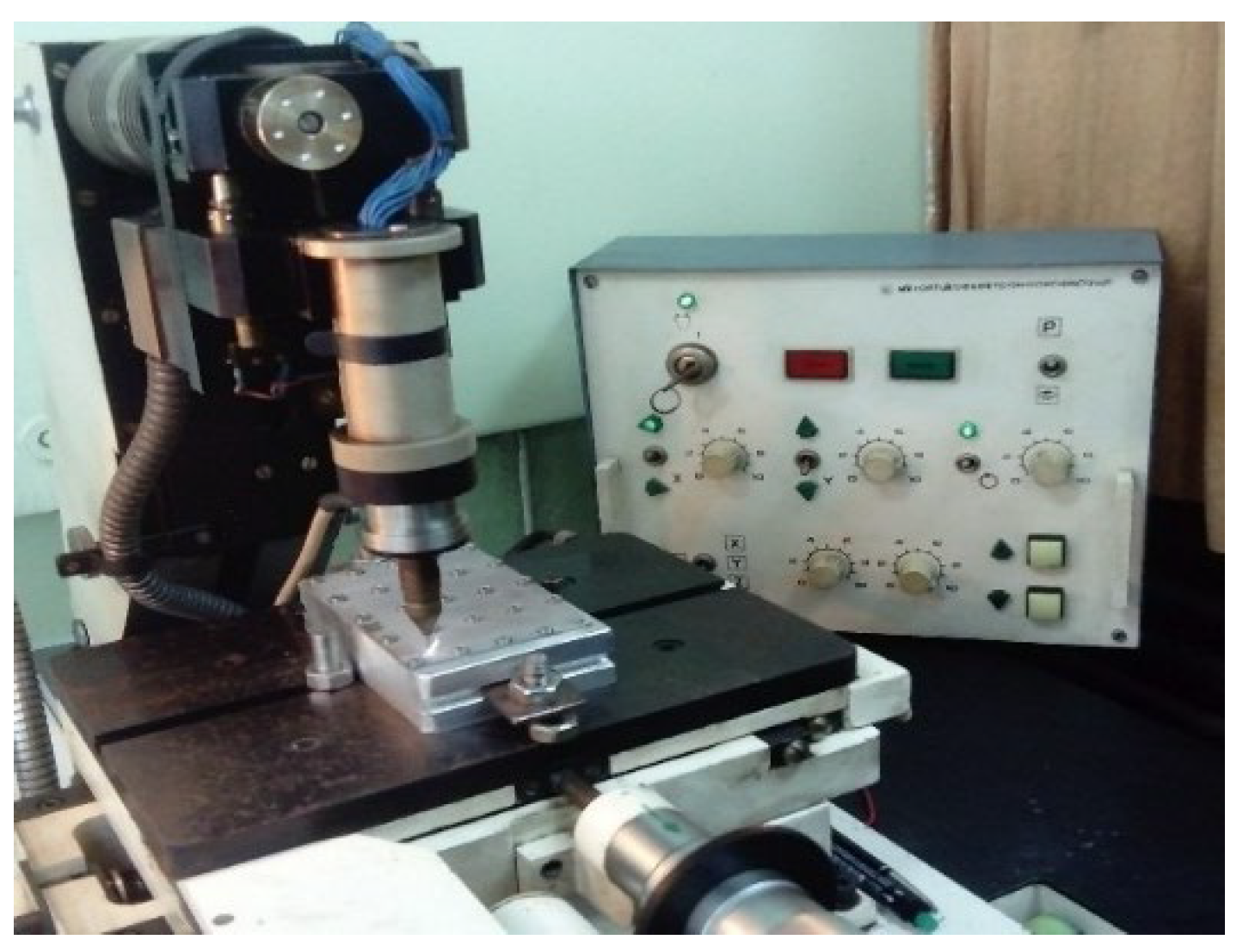
Figure 2.
General view of LESD coatings deposited with TiB2-TiAl electrode on Ti-Gr2 substrate.
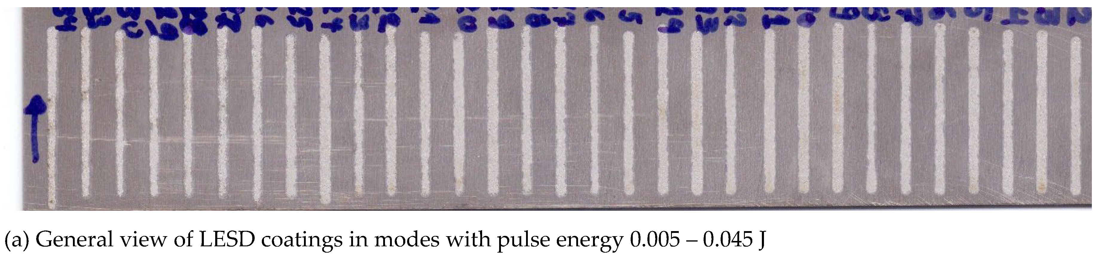
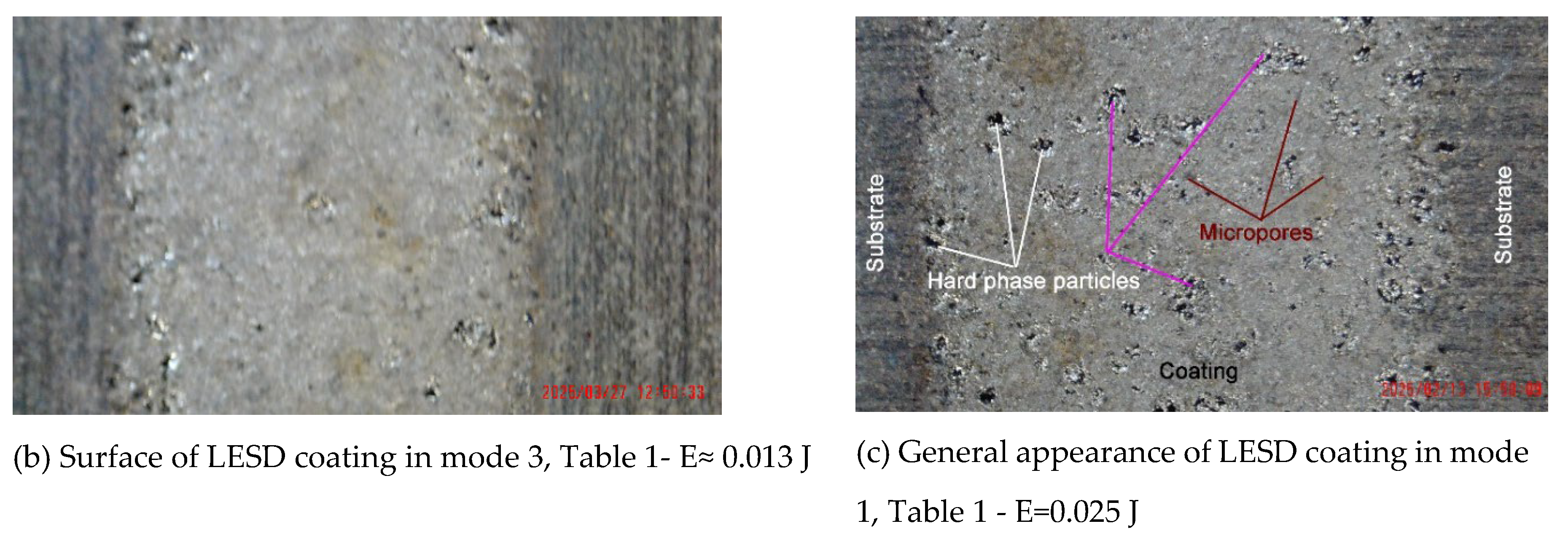
Figure 3.
Roughness and thickness of TiB2-TiAl nano coatings on Ti GR2 vs. the pulse energy (substrate Ra≈2.5 μm).
Figure 3.
Roughness and thickness of TiB2-TiAl nano coatings on Ti GR2 vs. the pulse energy (substrate Ra≈2.5 μm).
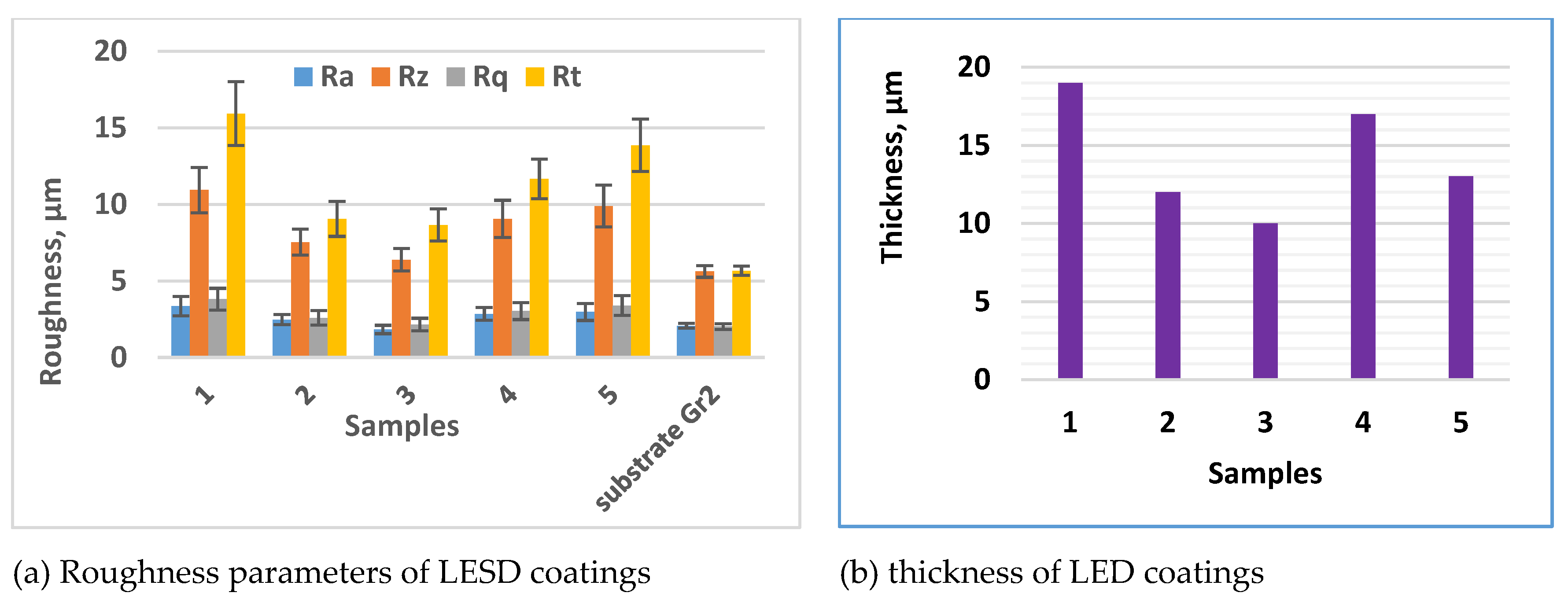
Figure 4.
SEM images of surface view on top of TiB2-TiAl nano coatings.
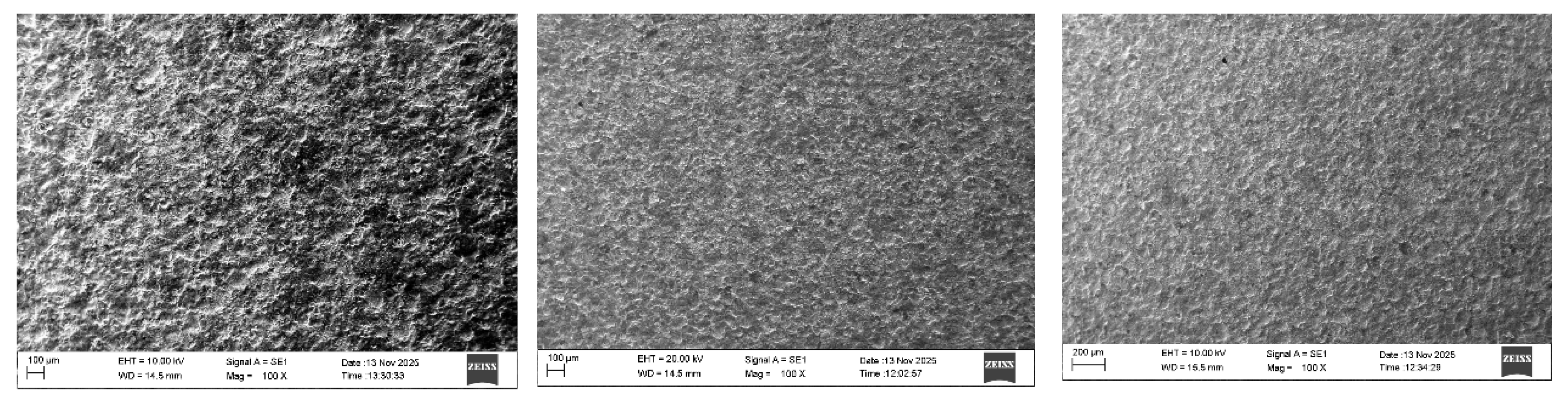
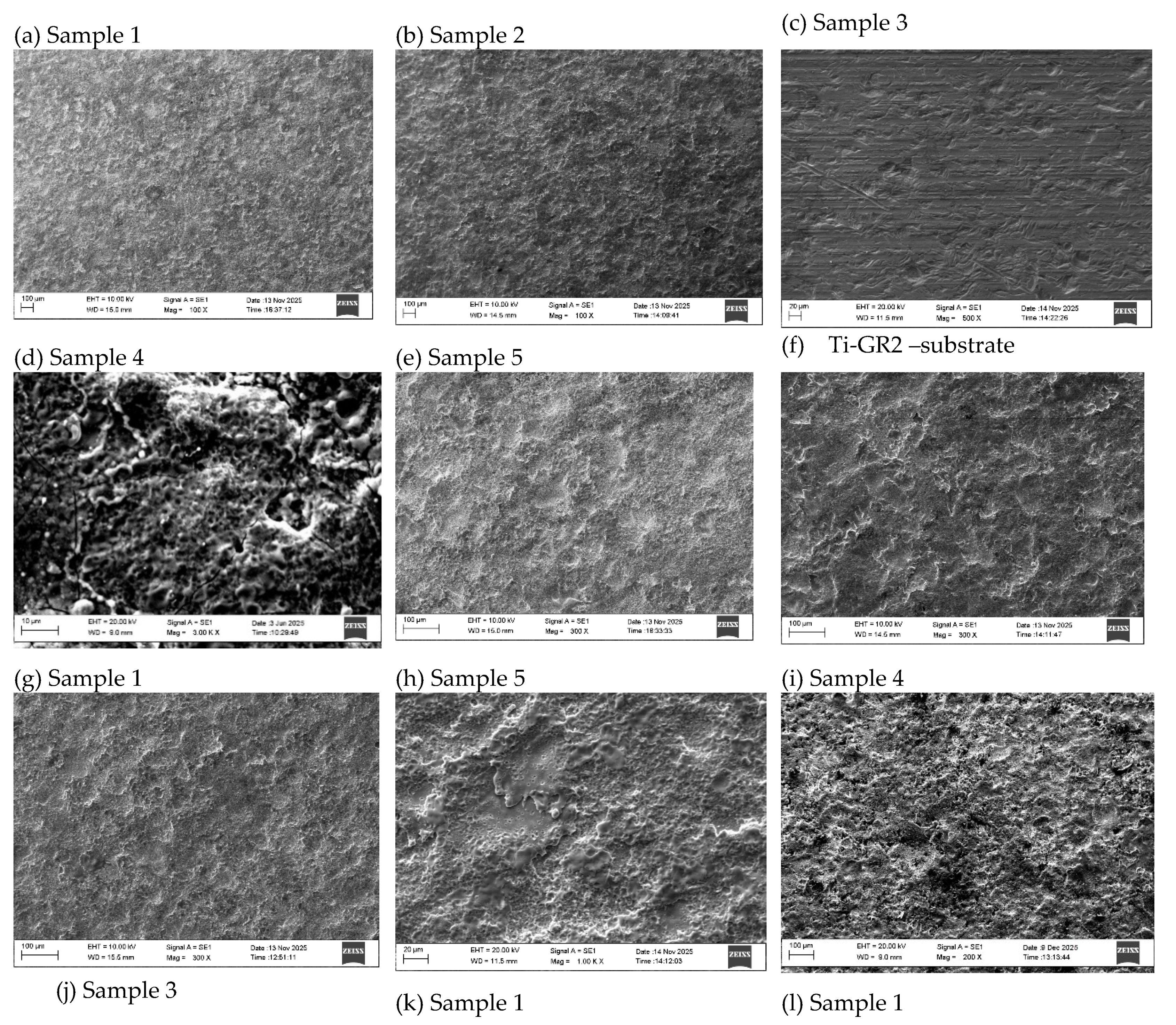
Figure 5.
Cross- section microphotographs of microstructure of coatings from TiB2-TiAl electrodes.
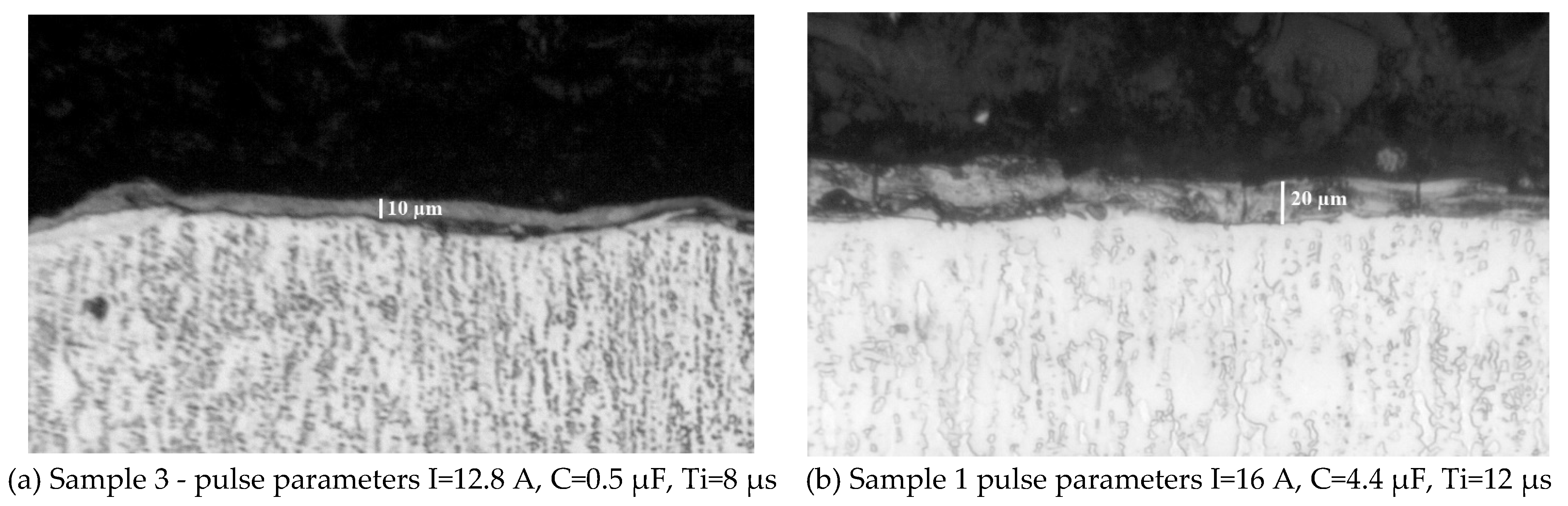
Figure 6.
XRD diffraction patterns of coatings from TiB2-TiAl electrode on at different pulse energy.
Figure 6.
XRD diffraction patterns of coatings from TiB2-TiAl electrode on at different pulse energy.
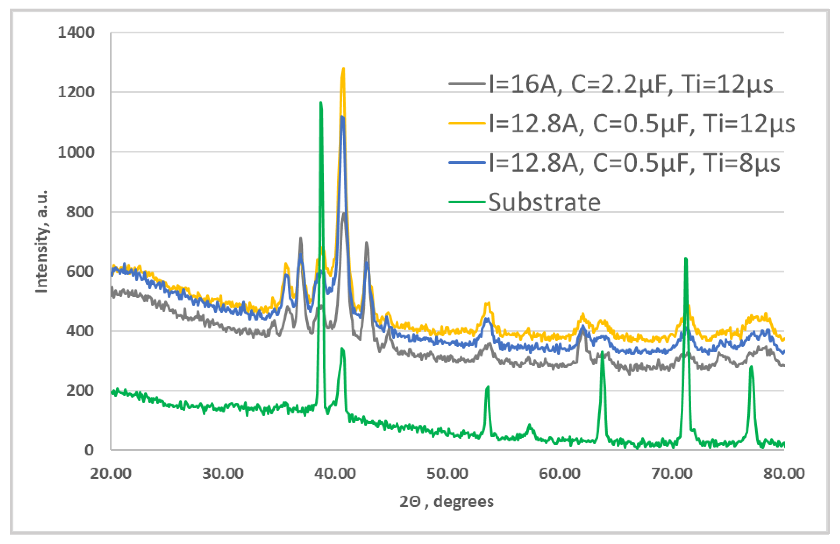
Figure 7.
The EDX spectrum of the Ti-GR 2 substrate.
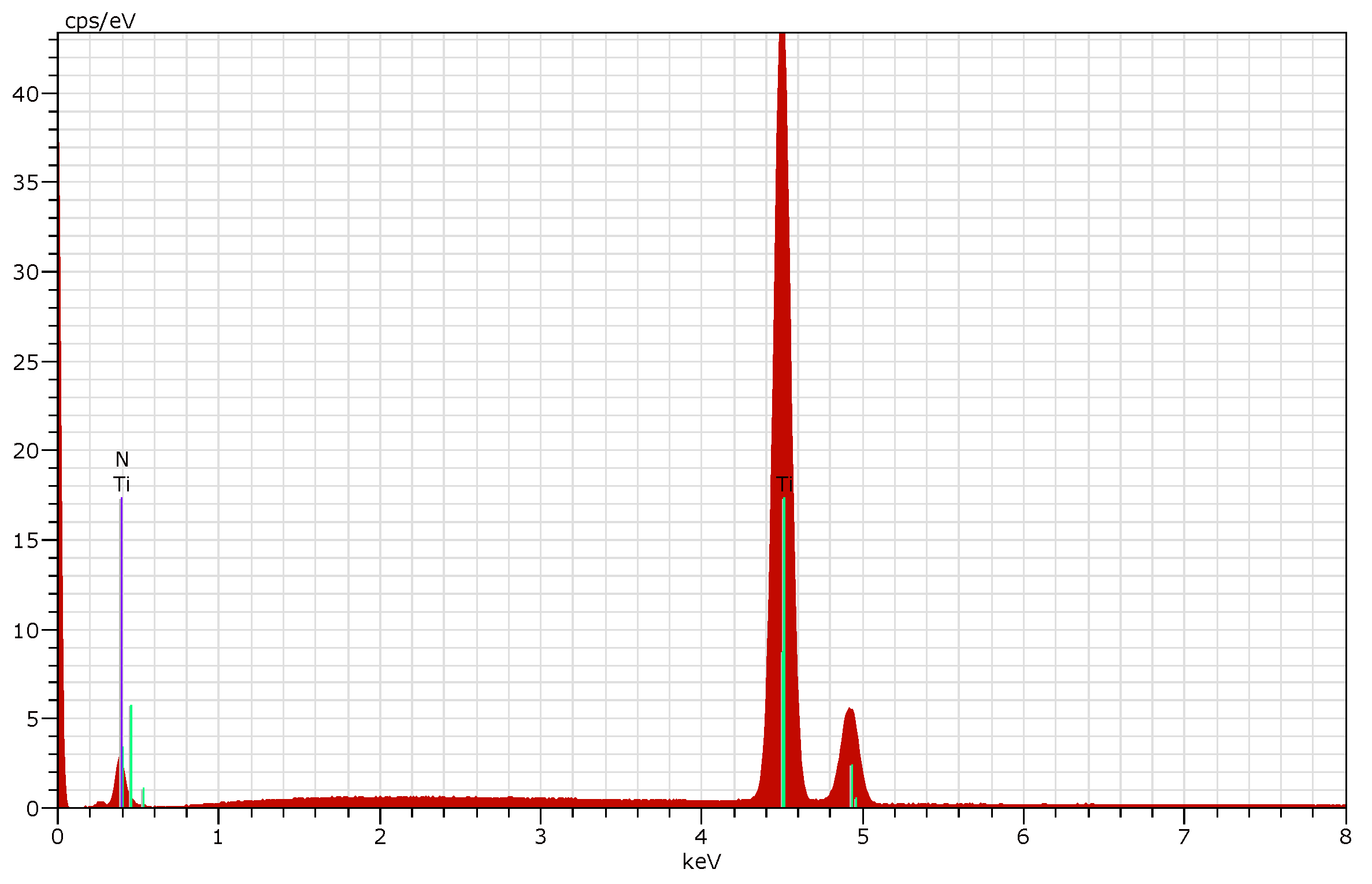
Figure 8.
EDX of coating TiB2-TiAl – Sample 4.
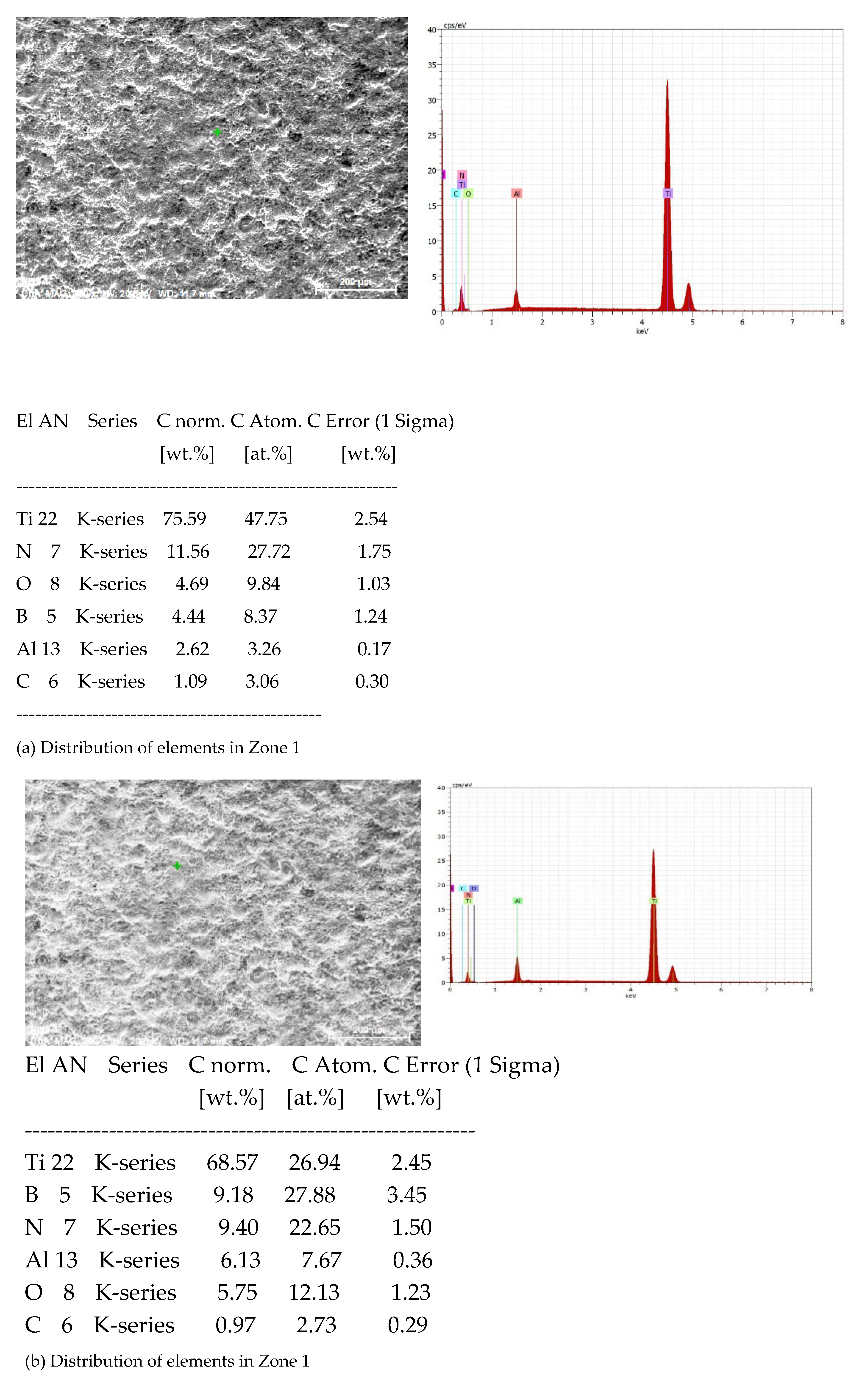
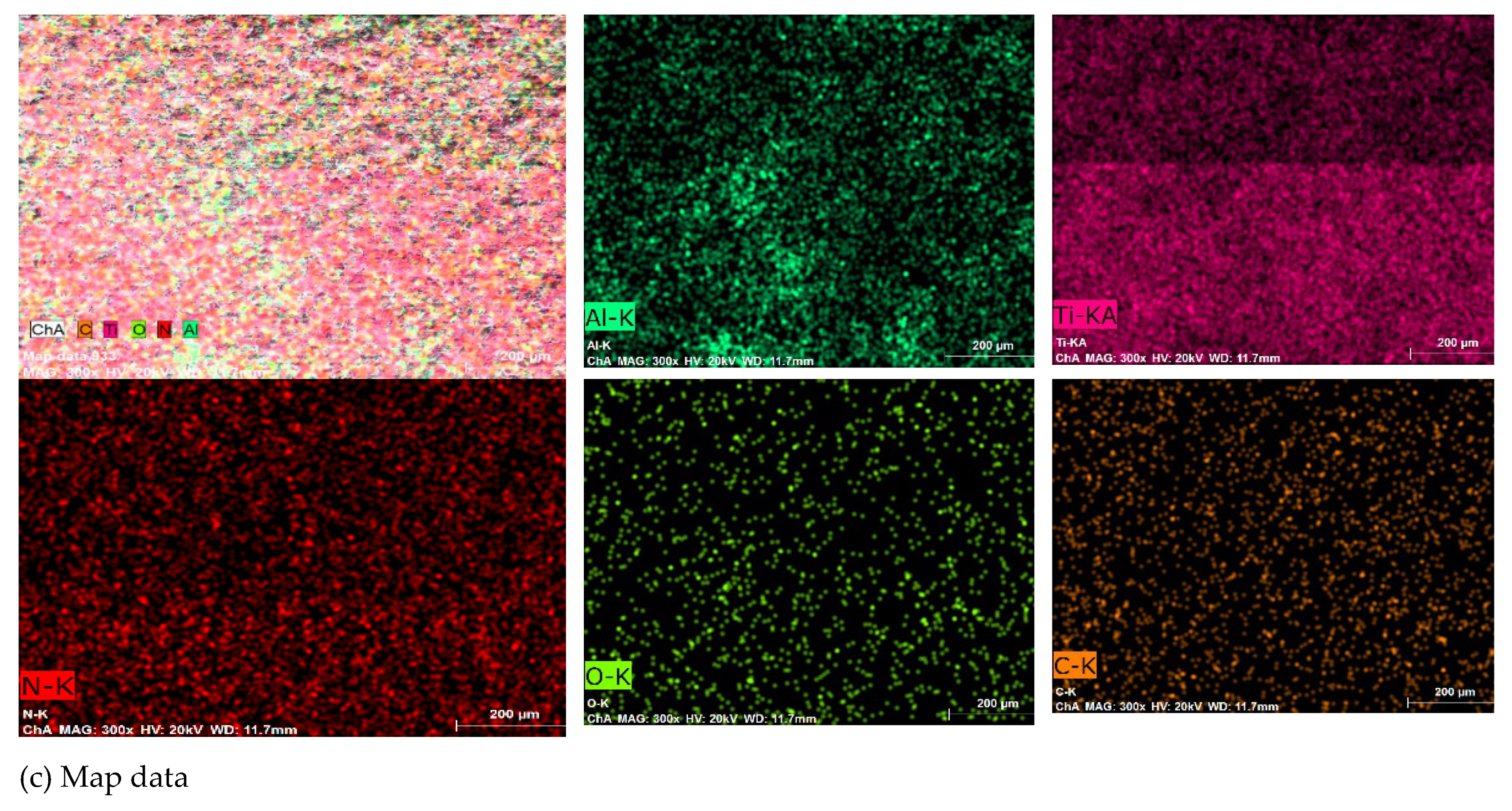
Figure 9.
EDX of TiB2-TiAl coating– Sample 5.
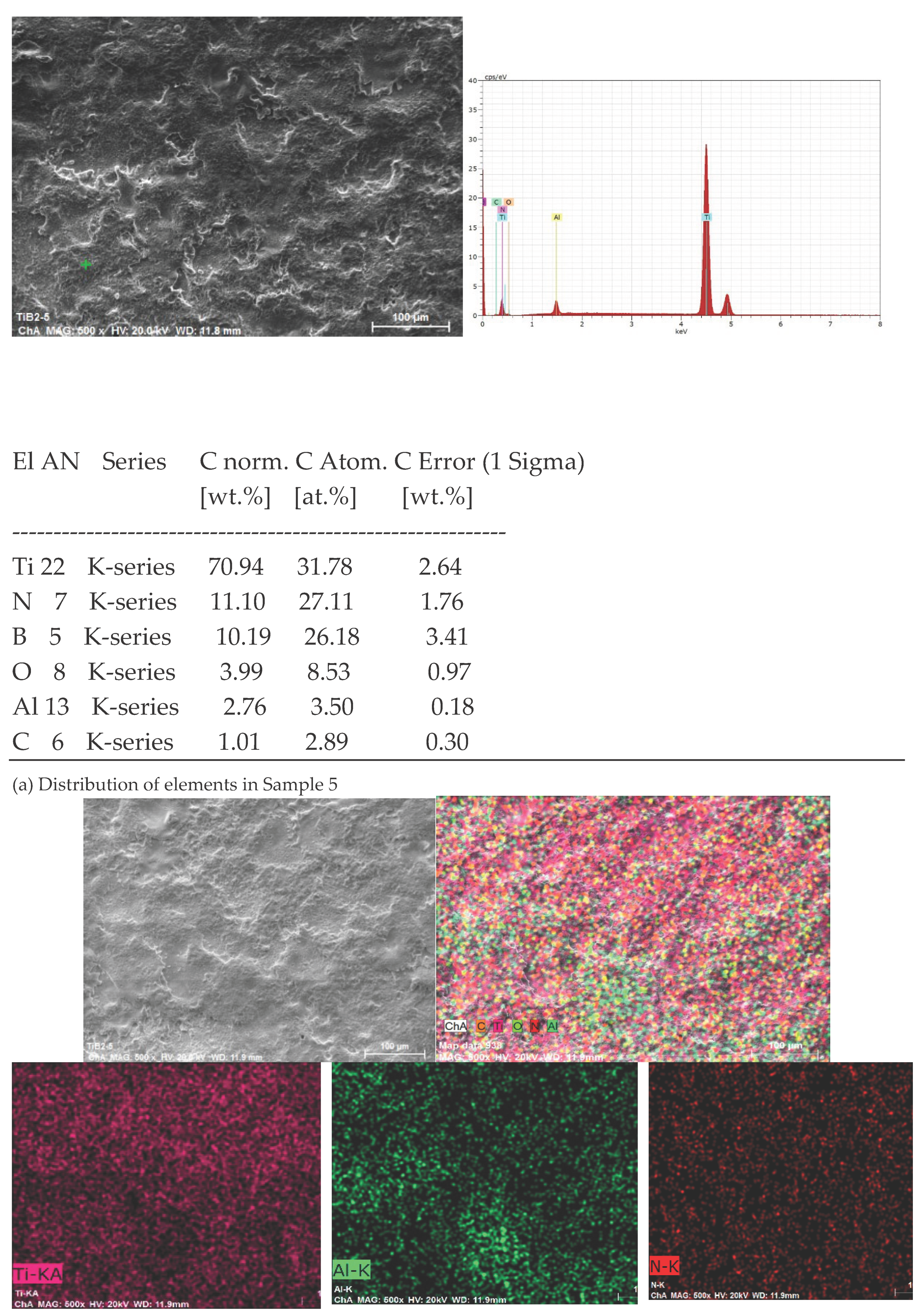
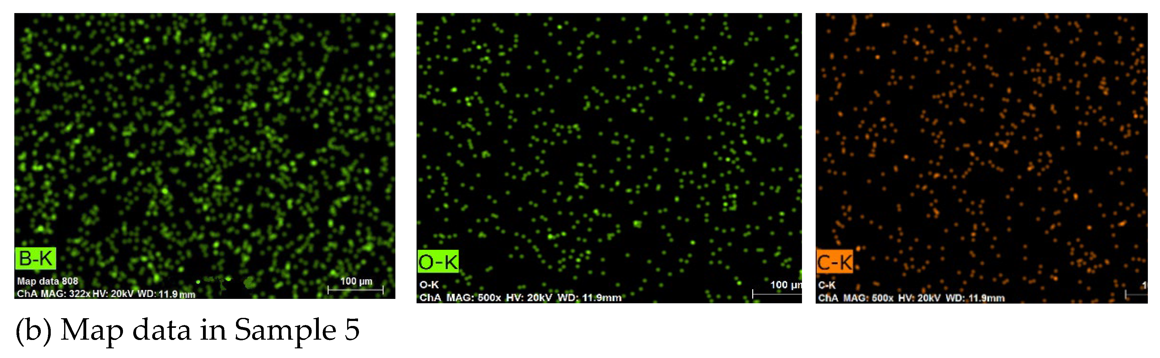
Figure 10.
Average, minimum and maximum values of microhardness HV, Universal hardness HU of LESD coatings from TiB2-TiAl electrode under different regimes.
Figure 10.
Average, minimum and maximum values of microhardness HV, Universal hardness HU of LESD coatings from TiB2-TiAl electrode under different regimes.
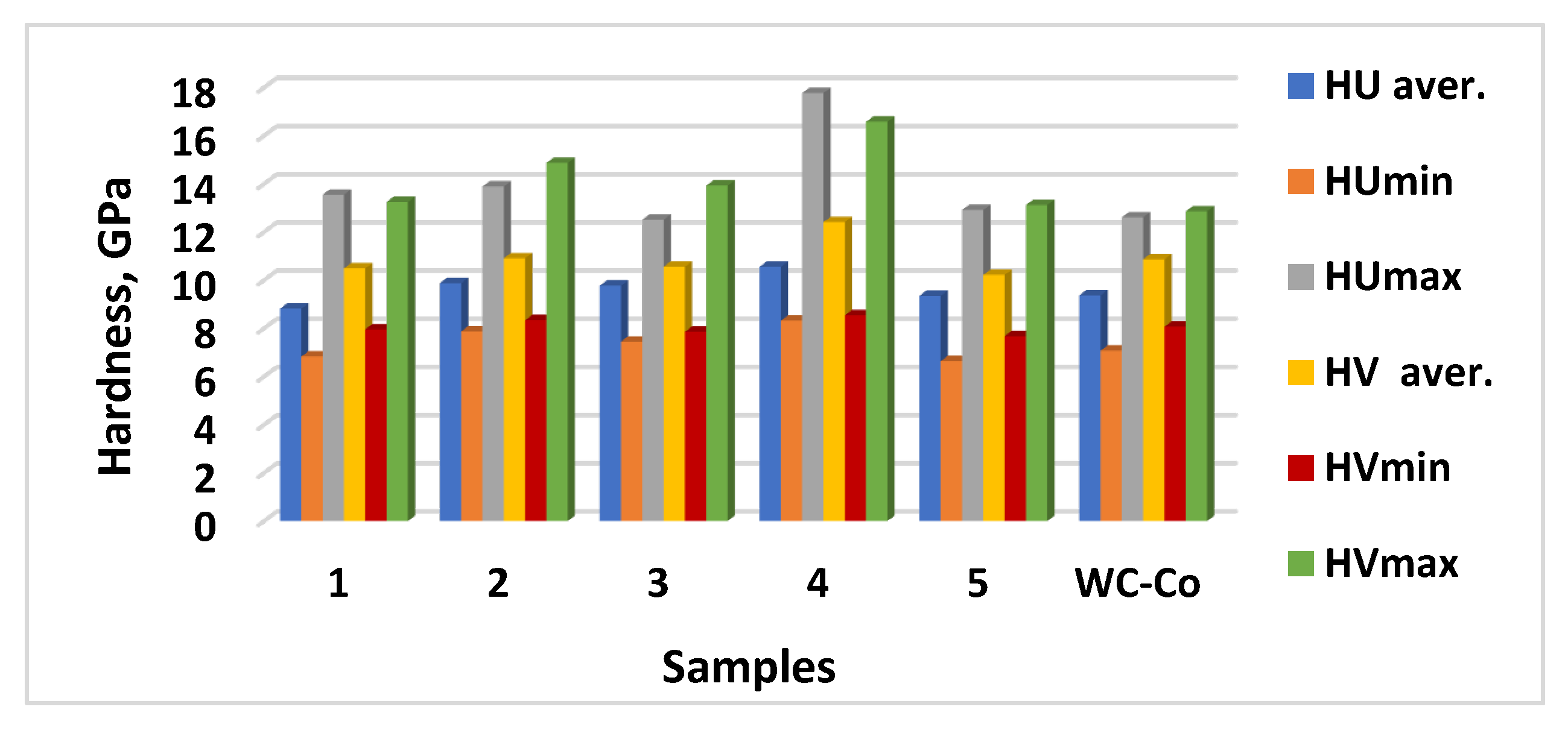

Table 1.
Parameters of the selected modes for LES.
| N | Designation | Current, I, A | Capacitance, C, μF | Pulse duration, Ti, μs | Frequency, f, kHz | Pulse energy, E, J | ||
|---|---|---|---|---|---|---|---|---|
| 1 | Sample 1 | 16 | 4,4 | 12 | 8,33 | 0,025 | ||
| 2 | Sample 2 | 11,2 | 0,5 | 12 | 8,33 | 0,013 | ||
| 3 | Sample 3 | 12,8 | 0,5 | 8 | 12,5 | 0,013 | ||
| 4 | Sample 4 | 16 | 2 | 12 | 8,33 | 0,02 | ||
| 5 | Sample 5 | 12,8 | 4,4 | 8 | 12,5 | 0,02 | ||
Table 2.
Phase composition of the coatings - samples 2,3 and 4.
| Main phases |
2θ0 |
Рhases in small amounts |
2θ0 |
Traces of phases |
2θ0 |
|---|---|---|---|---|---|
|
α-Ti |
35.38;38.5;40.2;53;63;70.8;74;76.2;77.2 | AlTi |
38.72;45.6;65.35;66.05;70.5;78.45;79.20 | Al,≈ | 38.5;44.7;65 |
|
AlTi3 |
26.33;31.12;35.65;38.8;39.4;40.8;43.05;53.8 | Ti6O |
34.9;37;38.4;40;52.5;70.1;75.6 | TiC0.7N0.3 | 35;42;61;72.9 |
| TiN | 36.95;42.95;62.2;74.5;78.5 | Ti3O |
37.8;39.9;52.1;62.5;69.6;75.3 | AlN | 20.5;33.2;36.2;38.1;59.4;61;66;70; 71.8;72.7 |
|
TiB2 |
27.7;33.38;34.2;44.6;56.9;61.1;67.9;72;78.6 | TiC0.3N0.7 |
36.5;74.5 | AlB | 21.5;23.3;36.8 |
|
TiN0.3 |
35;37.5;39.5;52.2;62.5;69.2;75.5;77 | Al2O3 |
19.5;32.1;35.65;37.6;39.2;43.05;44.5;45.6;50;56.7;60.5;66.8;71.4;75.3;78.55 | BN | 43.1;74;76 |
|
TiB |
37.05;42.95;62.25;78.5 | Ti2O |
33.6,35.65;38.45;40.7;53;63.7;70.5;76.6;77.15;78.5 | Al2.86O3.45N0.55 | 32;37.5;45.8;66.5;69.5 |
|
Ti3.2B1.6 N2.4 (Ti4N3B2)0.8 |
33.36;37;42.95;62.25;74.5;78.5 | TiC1-x | 35.9;41.7;60.3;72.2 | Al3Ti |
25.5;33.5;39.5;42.2;46;48;55;65.8;66.6;70;75.3 |
Table 3.
Range of crystallite sizes of the phases in the LESD coatings of TiB2-TiAl electrodes deposited under the regimes from Table 1.
Table 3.
Range of crystallite sizes of the phases in the LESD coatings of TiB2-TiAl electrodes deposited under the regimes from Table 1.
| Рhases | α-Ti | TiN | TiN0.3 | TiC0.3N0.7 | TiB2 | TiB | Ti3.2B1.6N2.4 | Al3Ti | Ti3O | Ti2O | Al2O3 | TiC1-x | AlN | AlTi |
|---|---|---|---|---|---|---|---|---|---|---|---|---|---|---|
|
Crys tallite size, nm |
26-87 | 13-66 | 31- 46 |
6 - 51 | 15- 78 | 14-55 | 31-53 | 26- 49 |
17-44 | 33- 40 |
22- 76 | 10-44 | 14-37 | 22-49 |
Disclaimer/Publisher’s Note: The statements, opinions and data contained in all publications are solely those of the individual author(s) and contributor(s) and not of MDPI and/or the editor(s). MDPI and/or the editor(s) disclaim responsibility for any injury to people or property resulting from any ideas, methods, instructions or products referred to in the content. |
© 2025 by the authors. Licensee MDPI, Basel, Switzerland. This article is an open access article distributed under the terms and conditions of the Creative Commons Attribution (CC BY) license (http://creativecommons.org/licenses/by/4.0/).
Copyright: This open access article is published under a Creative Commons CC BY 4.0 license, which permit the free download, distribution, and reuse, provided that the author and preprint are cited in any reuse.


