
Submitted:
26 December 2025
Posted:
29 December 2025
You are already at the latest version
Abstract
Optical amplification and spatial multiplexing technologies have important applications in quantum communication, quantum networks, and optical information processing. In this paper, based on the non-reciprocal amplification of a pair of co-propagating conjugate four-wave mixing (FWM) signals induced by a one-way pump field in a double-Λ-type hot atomic system, we demonstrate a spatially multiplexed multiple FWM processes by introducing a counter-propagating collinear pump field. This configuration enables simultaneous amplification of bidirectional four-channel FWM signals. Furthermore, when the injected signal and pump beams are modulated to Laguerre-Gaussian beams carrying different optical orbital angular momentum (OAM), the OAM of the pump beam is transferred to each amplified field. Through the tilted lens method, we experimentally demonstrate that the OAM of the amplified signal light remains identical to that of the original injected signal light. In contrast, the OAM of the other three newly generated FWM fields are governed by the angular momentum conservation law of their respective FWM processes, which enables the precise manipulation of the OAM for the other generated amplified fields. Theoretical analysis of the dynamical transport equation for the density operator in light-matter interaction processes fully corroborates the experimental results. These findings establish a robust framework for developing OAM-compatible optical non-reciprocal devices based on complex structured light.
Keywords:
multiple four-wave mixing
; optical amplification
; orbital angular momentum
; vortex beam
; hot atoms
1. Introduction
Optical amplification and spatial multiplexing technologies play a crucial role in overcoming the limits of information transmission capacity and enhancing information processing speed [1,2,3]. These technologies have wide-ranging applications in quantum communication and photonic quantum networks. A major challenge lies in achieving multi-channel and high-efficiency optical signal amplification while preserving the quantum properties of high-dimensional information encoding and signal transmission [4]. Orbital angular momentum (OAM), which corresponds to orthogonal spatial modes with different topological charges, theoretically offers infinite-dimensional information encoding resources. OAM-based spatial multiplexing technology can construct high-dimensional Hilbert spaces, providing a critical physical foundation for high-capacity quantum communication, parallel quantum computing, and complex quantum state simulation and manipulation [5,6,7,8]. However, traditional optical amplification technologies face challenges such as gain imbalance and mode crosstalk when simultaneously amplifying multiple channels and preserving OAM modes [9,10]. These limitations constrain their applicability to complex quantum systems requiring high-dimensional and high-fidelity operation.
Four-Wave Mixing (FWM) is a parametric process originating from the third-order nonlinear polarization of media, exhibiting unique characteristics including low noise, phase sensitivity, tunable bandwidth, and the capacity to generate quantum-correlated photon pairs [11,12,13]. As such, it has become a core nonlinear technology for achieving near-noiseless optical amplification [14,15], all-optical wavelength conversion [16,17], all-optical quantum gate operations [18,19], and deterministic quantum light sources [20,21]. However, traditional FWM systems driven by a single pump field face fundamental limitations in channel number scalability and OAM mode integration, which fall short of meeting the evolving demands of photonic quantum information technology for higher-dimensional and more complex architectures [22,23]. In recent years, significant advancements have been achieved in FWM utilizing alkali metal atoms (such as rubidium and cesium). The incorporation of electromagnetically induced transparency (EIT) enables the formation of highly coherent dark states near atomic resonance transition frequencies while simultaneously enhancing nonlinear optical responses. This breakthrough has opened new avenues for developing high-efficiency and low-noise FWM processes [24,25,26,27]. The applications of FWM have expanded from initial single-channel optical amplification [28,29,30] and correlated photon pair generation to the production of multiple correlated light beams through cascaded or parallel FWM configurations [31,32]. Nevertheless, most research efforts have predominantly focused on intensity or frequency multiplexing approaches [33,34], with comparatively limited attention devoted to the cooperative amplification and precise spatial mode manipulation of light fields.
As a prototypical multi-level system, the double-Λ atomic energy level configuration demonstrates pronounced nonlinear optical phenomena and exceptional controllability under the coherent interaction of multiple light fields, thereby serving as an ideal platform for realizing efficient multi-channel FWM processes [35,36,37]. By introducing coupling fields and control fields at distinct transition energy levels, the atomic system enables the construction of dual or multiple EIT windows. This not only effectively suppresses the linear absorption of probe light across multi-frequency channels but also concurrently enhances the third-order nonlinear susceptibility in the vicinity of multiple resonant frequency points, thereby facilitating the realization of multi-channel optical amplification based on FWM [38,39]. Moreover, the system opens a new avenue for the parallel processing and coherent manipulation of multi-dimensional photon quantum states, including those carrying OAM [40,41,42].
In this study, we propose and implement a four-channel optical amplification transmission scheme utilizing multiple FWM in a double-Λ cesium atomic system. Under the action of a single pump field, the nonreciprocal amplification (NRA) of co-propagating dual FWM fields is achieved by accounting for the Doppler effect of thermal atoms. Subsequently, by introducing a counter-propagating collinear pump field, a spatially multiplexed multi-FWM process is established, enabling bidirectional four-channel FWM signal amplification. Furthermore, we use spiral phase plates (SPP) to modulate the signal and pump beams to high-order Laguerre-Gaussian (LG) beams carrying different OAM quantum numbers, then experimentally and theoretically investigate the transfer characteristics of OAM among various FWM fields driven by the double counter-propagating pump fields. This scheme not only surpasses the channel number limitations of conventional FWM techniques but also significantly enhances spatial multiplexing capacity through the integration of OAM degrees of freedom. It thereby provides a novel approach for constructing high-capacity, multi-dimensional optical quantum information processing systems.
2. Experimental Setup and Results Analysis
The energy level diagrams of the atoms are shown in Figure 1 (a). A double-Λ atomic system includes two ground states |1⟩ and |2⟩ and one excited state |3⟩. This system can be realized in the D1 line of the 133Cs atoms with |6S1/2, F=4⟩, |6S1/2, F=3⟩ and |6P1/2, Fʹ=4⟩ acting as states |1⟩, |2⟩ and |3⟩, respectively. The frequency difference between the two lower levels is δ≈9.192 GHz. The two transitions |1⟩→|2⟩ and |1⟩→|3⟩ are simultaneously driven by two strong counter-propagating pump fields (forward pump field PF and backward pump field PB with same frequency ωP) with different single-photon detunings Δ=ωP –ω31 and Δ-δ. The transition |3⟩ to |2⟩ is also coupled by a weak signal light S with frequency ωS and detuning ΔS=ωS –ω32. The multiple FWM can be satisfied when ΔS =Δ, that is, while S is being amplified, three new FWM fields are simultaneously generated, which denoted as C, S′ and C′.
The schematic diagram of our experimental setup is shown in Figure 1 (b). We use two continuous frequency-tuned diode lasers, each shaped to fundamental mode Gaussian beam (TEM00) by optical fibers, as the strong pump beam and the weak signal beam, respectively. The strong pump beam is divided into two parts, PF and PB, which are reflected to the L=25 mm-long Cs cell with vertical polarization through two Glan-Taylor prisms (GT1 and GT2, with the extinction ratio of 105:1) in a collinear opposite direction. The weak signal beam S is reflected by a beam splitter (TS, with reflectivity 1%), and is then passed through the Cs cell with horizontal polarization to overlap with the PF at a small angle θ (θ≈0.23°). The e−2 beam widths of PF, PB and S at the center of the cell are approximately 0.69 mm, 0.68 mm, and 0.49 mm, respectively. The cell temperature is stabilized at Tcell=100 °C. The forward FWM fields S and C are detected by PD1 and PD2, and the backward FWM field S′ and C′ are detected by PD3 and PD4, respectively.
Figure 2 shows the normalized transmission spectra under different pumping conditions. When only the forward PF and S are injected into the Cs cell, the forward FWM process occurs due to the phase-matching relation is achieved in this forward Doppler-free configuration, which satisfies the condition of nonreciprocity amplification [43,44,45]. At the two-photon resonance (e.g., ΔS =Δ≈1.1 GHz), S is amplified, and a newly forward conjugate beam C is created in the same direction of its symmetry with the PF field, as shown by the red and blue curves in Figure 2 (a). At this time, no backward beams can be detected by PD3 and PD4, as shown by the light blue and green lines in inset of Figure 2 (a). Furthermore, when both PF and PB are present, multiple FWM processes occur simultaneously (see Figure 1). Along the opposite directions of the S and C, two new FWM beams denoted S′ and C′ are generated at the two-photon resonance, as shown the light blue and green curves in Figure 2 (b). The optical gain Gi of the FWM process is defined as the ratio of the output power Pi to the input signal power PS0 [46], i.e., Gi = Pi/PS0 (i=S, C, S′ and C′). By comparing Figure 2(a) and 2(b), it can be seen that on the basis of forward FWM (only PF injected), when the PB is introduced, the gain of the forward FWM fields GS increases from 1.5 to 3, while GC increases from 1.2 to 3.9. At this time, the gain of new generate backward FWM fields GS′ ≈2.3, and GC′ ≈1.8.
Actually, the four-channel optical amplification of Figure 2(b) is the result of the mutual superposition and enhancement of multiple FWM processes which include four interactions processes between light and atoms, as shown in Figure 3. The first FWM process (named FWMf) is induced under the action of forward PF and S fields [see Figure 3(a1)]: The atom initially in the ground state |1⟩ first absorbs a forward pump photon PF and is stimulated to the excited state |3⟩, and then emits a forward signal photon S and jumps to another ground state |2⟩. Immediately after, the atom absorbs a forward pump photon PF and is stimulated to the excited state |3⟩, and finally emits a forward conjugate photon C, and finally jumps back to the ground state |1⟩. FWMf can be described as (A and E represent the absorption and emission of the atom, respectively), with energy conservation relation 2ωP=ωS+ωC and phase matching relation 2kPF=kS+kC, see Figure 2 (b1). When considering the backward PB, the forward amplified S and generated C can respectively serve as seed beam, interacting with the two counter-propagating pump fields (PF and PB) to generate two additional FWM processes, named as FWMS and FWMC, as shown in Figure 3 (a2) and (a3). The interaction process of FWMS can be expressed as with 2ωP=ωS+ωS′ and kPF+kPB=kS+kS′ [see Figure 3 (b2)], and that of FWMC can be expressed aswith 2ωP=ωC+ωC′ and kPF+kPB=kC+kC′ [see Figure 3 (b3)]. Finally, the newly generated S′(C′) and PB contribute the backward FWM (named as FWMb) expressed as with 2ωP=ωS′+ωC′ and 2kPB=kS′+kC′ , as shown in Figure 3 (a4) and (b4).
If the fundamental Gaussian optical fields injected into the Cs vapor cell are replaced by vortex beams carrying lℏ OAM (l is the OAM quantum number), the topological charge can also be transferred into the generated FWM beams through multiple phase-matched FWM interaction which in accordance with the principle of OAM conservation [9,10]. That is, the rules should be 2lPF=lS+lC for FWMf, lPF+lPB =lS+lS′ for FWMS, lPF+lPB =lC+lC′ for FWMC and 2lPB=lS′+lC′ for FWMb. Furthermore, to validate this inference, we employed spiral phase plate (SPP, which includes one vortex phase plate and two quarter-wave plates) to modulate PF, PB, as well as S into Laguerre-Gaussian (LG) beams [see Figure 1 (b)], respectively, and observed the output pattern of the four amplified FWM fields by a camera.
When the injected S is modulated to LG01 mode with lS=1, and the two counter-propagating pump beams PF and PB are both in the TEM00 mode (lPF=lPB=0), the four output FWM fields in both forward and backward directions exhibit LG01 modes, while the modes of PF and PB remain unchanged, as shown the top in Figure 4 (a) and (b). Using the tilted lens method [47,48],the OAM quantum numbers of the forward amplified FWM fields are: lS=1 and lC=-1, see the bottom in Figure 4 (a), and those of the backward generated FWM fields are lS′=-1 and lC′=1, see the bottom in Figure 4(b). Obviously, the experimental results demonstrate that all the four FWM processes adhere to the angular momentum conservation principle.
Actually, in each complete four-wave mixing process, while atoms absorb two pump photons and emit a pair of conjugate photons, OAM is simultaneously transferred from the pump photons to the amplified photons, in which the topological charge number transferred to each four-wave mixing light field depends on the original topological charge number of the injected signal light. Taking lPF=1, lPB=0 as an example, when the pattern of the injected S is TEM00, it is found that the OAM quantum number of the amplified S contains unchanged with lS=0, and that of the generated C is modulated to lC=2 according to angular momentum conservation in FWMf, as shown in Figure 5 (a). At the same time, the backward generated S′ (C′) is changed to LG01 with lS′=1 (lC′=-1) by the process of FWMS (FWMC), as shown in Figure 5(b). As for the FWMb, the angular momentum conservation is also satisfied. Similarly, for the case of lPF=0, lPB=1, the forward S and C are the same OAM quantum number with lS= lC=0, and those of the backward S′ and C′ are the same with lS′=lC′=1, as shown in Figure 5(c) and (d).
3. Theoretical Simulation of OAM Transfer
In order to quantitatively describe the dynamic behavior of OAM conversion in the multiple FWM processes, here we give the theoretical simulation using semiclassical approach. See Figure 1(a), under the condition of two counter-propagating pump fields, the Hamiltonian of the system can be shown as:
where ћ is the reduced Planck constant, Ωi=μEi/ ћ (i=PF, PB, S, C, S′, C′) denotes the Rabi frequency of each field in multiple FWMs, and h.c. represents the Hermitian conjugate term. By inserting the Hamiltonian from Equation (1) into the Liouville–von Neumann equation (see Appendix A (A1)), and using the rotating wave approximation (see Appendix A. (A2a)-(A2d)), we obtain the zero-order coupled equations (see Appendix A. (A3a)-(A3i)) and the first-order coupled equations (see Appendix A. (A4a)-(A4g)) for the density matrix elements. we then derive the expressions for the atomic coherence terms ,,and under the first-order approximation of the four output optical fields. AS(S′), AC(C′), BS(S′) and BC(C′) are the parameters and their expressions see Appendix B.
Combining with the coupled Maxwell-Bloch equations describing the propagation of optical fields in the medium [49], the evolution equations for the four output optical fields along the propagation direction z of the medium are derived as:
where η=3N0λГ/4π is the coupling constant (N0 is atomic number density, λ is wavelength, and Г is attenuation coefficient). When numerically solving the above evolution equations, the initial conditions are set as: ΩS(z=0)=ΩS0, and ΩC (z=0)=0, ΩS′(C′) (z=L)=0
To compare with the three different combinations of input OAM topological charges verified experimentally (the experimental configurations are shown in Figure 4 and Figure 5), we conducted corresponding theoretical simulations and obtained the intensity and phase patterns of the four output optical fields. First, for the first topological charge configuration: lS=1 and lPF=lPB=0, Figure 6 (a1)-(a4) show that the intensity distributions of all four output fields exhibit typical annular structures with a phase singularity (dark core) at the center of the ring, indicating they are all vortex beams. The core criterion for the topological charge of OAM can be characterized by the azimuthal evolution of the helical phase distribution: a phase variation of 2π corresponds to a topological charge l=1 when rotating counterclockwise around the optical axis for a full cycle, whereas a phase variation of -2π corresponds to l=-1 when rotating clockwise for a full cycle. As shown in Figure 6 (b1)-(b4), the topological charges of the output S and C’ satisfy: lS=lC′=1, and the topological charges of the output fields S’ and C satisfy: lC=lS′=-1.
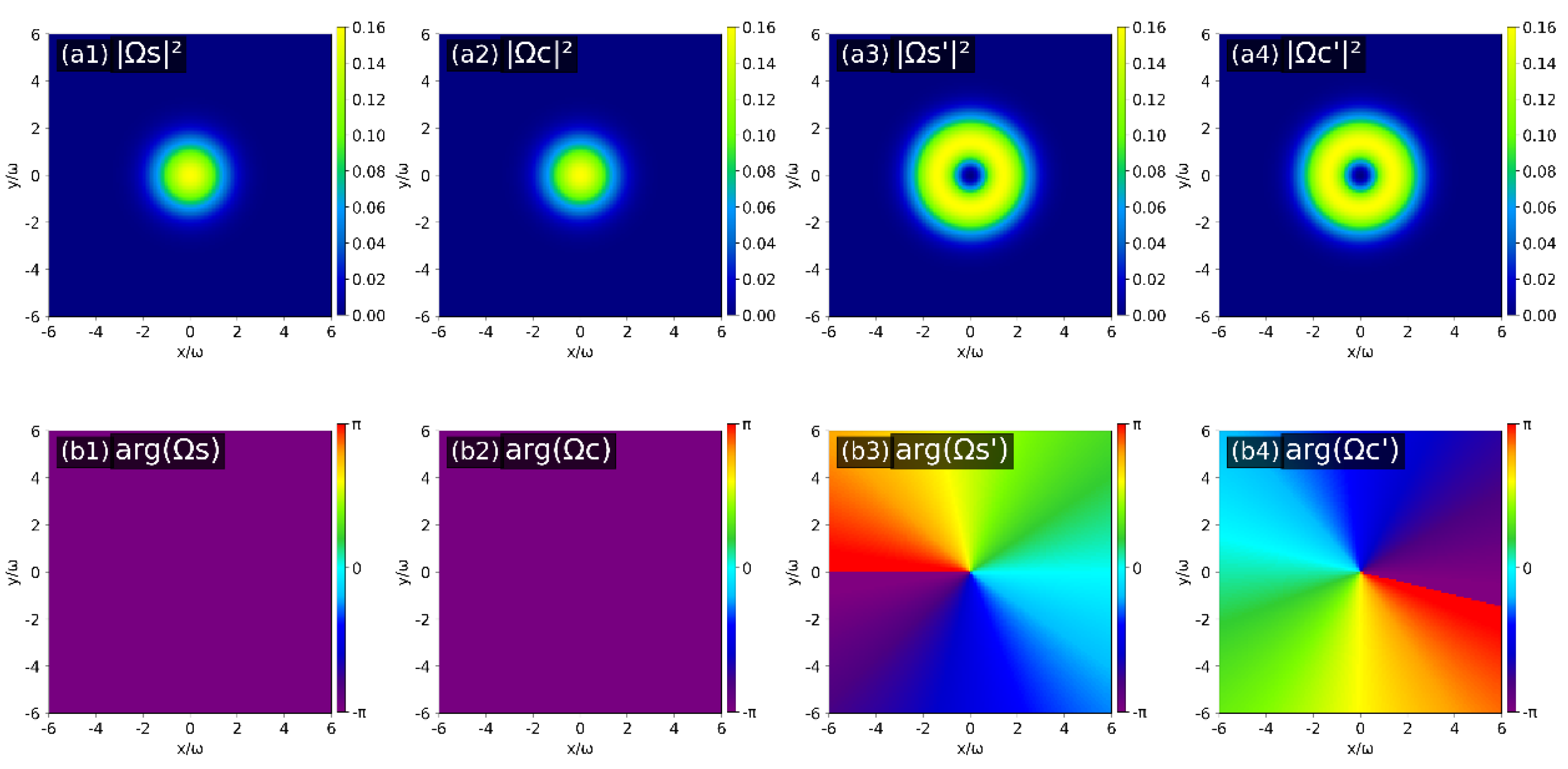
Similarly, considering the second topological charge configuration (lPF=1, lS=lPB =0) and the third topological charge configuration (lPB=1, lS=lPF=0), the results are shown in Figure 7 and Figure 8, respectively. By combining the helical characteristics of the phase distributions and the phase evolution rule around the optical axis, the OAM topological charges of the four output fields under the two configurations are obtained as follows: for the second case: lS=0, lC=2, lS′=1 and lC′=-1; for the third case: lS=lC=0, lS′=lC′=1.
The above three theoretical simulations are agree well with the experimental results, and demonstrate that in our multiple FWM processes, whether it’s FWMf or FWMS, when an atom absorbs a pump photon and emits a signal photon S, it always transfers the same topological charge as the initial injected signal photon. Then, in accordance with the law of angular momentum conservation, the topological charge of the newly generated conjugate photon C or S′ is determined. Furthermore, the topological charge of C′ can also be determined by FWMC or FWMb. Based on our experimental scheme, while achieving four-fold spatial multiplexing optical amplification, the OAM of each newly generated FWM signal can be effectively controlled by modulating the topological charge of the two counter-propagating pump fields.
4. Conclusions
In this research, a scheme of four-channel optical amplification is experimentally demonstrated based on the multiple-stimulated FWM processes in hot Cs atoms. With the action of a single pump field, the necessary condition for the generation of dual-channel conjugate NRA signals is the establishment of FWM in the same direction and break in the opposite direction. However, a pair of optical amplified signals can be generated in the opposite direction by introducing a counter-propagating pump field. Based on this, when the signal and pump lights are modulated into higher-order LG beams carrying OAM to participate in the FWM process, the transfer and conservation of OAM among various amplified FWM fields are verified, which achieves OAM transfer in higher dimensions. These results pave the way for realizing complex structured light non-reciprocal devices by modulating OAM. Since optical non-reciprocal devices such as optical isolators, circulators, and phase shifters are fundamental units of all-optical communication, this conclusion holds potential applications for achieving high-capacity optical communication and high-dimensional signal processing.
Data availability
Data underlying the results presented in this paper are not publicly available at this time but may be obtained from the authors upon reasonable request.
Disclosures
The authors declare no conflicts of interest.
Author Contributions
Conceptualization, X.L. and H.-T.Z.; methodology, D.W. and J.-X.Z.; software, Y.-X.F. and R.M.; validation, D.S. and Y.-X.F.; formal analysis, X.L. and D.W.; investigation, X.L. and R.M.; resources, B.-D.Y. and H.-T.Z.; data curation, X.L. and H.-T.Z.; writing—original draft preparation, X.L.; writing—review and editing, H.-T.Z. All authors have read and agreed to the published version of the manuscript.
Appendix A. Bloch Equation
The evolution of the system is given by the Liouville–von Neumann equation [29,30]:
and the density matrix elements in the rotating frame are:
After applying the Rotating Wave Approximation (RWA), the zero-order coupled equations for the density matrix elements are as follows:
Here the complex decay rates are defined as ,,and. We define that,,In a similar way, the first-order coupled equations for the density matrix elements are as follows:
and
Appendix B. Coefficients of Equations (2a)–(2d)
The coefficients Ai and Bi of the expressions in Equations (2a)–(2d) are given by
References
- Pan, X.; Yu, S.; Zhou, Y.; Zhang, K.; Zhang, K.; Lv, S.; Li, S.; Wang, W.; Jing, J. Orbital-angular-momentum multiplexed continuous-variable entanglement from four-wave mixing in hot atomic vapor. Phys. Rev. Lett. 2019, 123, 070506. [Google Scholar] [CrossRef]
- Zhang, K.; Wang, W.; Liu, S.; Pan, X.; Du, J.; Lou, Y.; Yu, S.; Lv, S.; Treps, N.; Fabre, C.; Jing, J. Reconfigurable hexapartite entanglement by spatially multiplexed four-wave mixing processes. Phys. Rev. Lett. 2020, 124, 090501. [Google Scholar] [CrossRef]
- Kawasaki, A.; Brunel, H.; Ide, R.; Suzuki, T.; Kashiwazaki, T.; Inoue, A.; Umeki, T.; Yamashima, T.; Sakaguchi, A.; Takase, K.; Endo, M. Real-time observation of picosecond-timescale optical quantum entanglement towards ultrafast quantum information processing. Nat. Photonics 2025, 19, 271. [Google Scholar] [CrossRef]
- Fan, Y.R.; Luo, Y.; Guo, K.; Wu, J.P.; Zeng, H.; Deng, G.W.; Wang, Y.; Song, H.Z.; Wang, Z.; You, L.X.; Guo, G.C. Optimized quantum entanglement network enabled by a state-multiplexing quantum light source. [CrossRef]
- Liu, S.; Lou, Y.; Jing, J. Orbital angular momentum multiplexed deterministic all-optical quantum teleportation. Nat. Commun. 2020, 11, 3875. [Google Scholar] [CrossRef]
- Li, S.; Pan, X.; Ren, Y.; Liu, H.; Yu, S.; Jing, J. Deterministic generation of orbital-angular-momentum multiplexed tripartite entanglement. Phys. Rev. Lett. 2020, 124, 083605. [Google Scholar] [CrossRef] [PubMed]
- Chen, Y.; Liu, S.; Lou, Y.; Jing, J. Orbital angular momentum multiplexed quantum dense coding. Phys. Rev. Lett. 2021, 127, 093601. [Google Scholar] [CrossRef]
- Yang, X.; Wang, C.; Wang, J.; Cao, M.; Chen, Y.; Chang, H.; Dong, R.; Zhang, S.; Wei, D.; Zhang, P.; Li, F. Efficient multiplexed quantum memory with high-dimensional orbital angular momentum states in cold atoms. Adv. Photonics 2025, 7, 056010. [Google Scholar] [CrossRef]
- Wen, T.; Gao, S.; Li, W.; Tu, J.; Li, J.; Xiao, Y.; Gao, H.; Chen, Y.; Zhao, J.; Du, C.; Liu, W. Orbital angular momentum mode-multiplexed amplification and transmission based on a ring-core erbium-doped fiber. J. Lightwave Technol. 2023, 41, 2116. [Google Scholar] [CrossRef]
- Gao, X.; Yu, Z.; Yao, J.; Mu, X.; Shi, Y.; Lai, P.; Li, B.; Song, Q. Discontinuous orbital angular momentum metasurface holography. Nat. Commun. 2025, 16, 10688. [Google Scholar] [CrossRef]
- Wang, H.; Zhang, Y.; Zhang, X.; Zhao, C.; Jin, S.; Jing, J. Multi-way noiseless signal amplification in a symmetrical cascaded four-wave mixing process. Photonics 2022, 9, 229. [Google Scholar] [CrossRef]
- Feng, L.T.; Cheng, Y.J.; Qi, X.Z.; Zhou, Z.Y.; Zhang, M.; Dai, D.X.; Guo, G.C.; Ren, X.F. Entanglement generation using cryogenic integrated four-wave mixing. Optica 2023, 10, 702. [Google Scholar] [CrossRef]
- Zhao, P.; Shekhawat, V.; Girardi, M.; He, Z.; Torres-Company, V.; Andrekson, P.A. Ultra-broadband optical amplification using nonlinear integrated waveguides. In Nature; 2025; pp. 1–6. [Google Scholar]
- Choi, S.-K.; Vasilyev, M.; Kumar, P. Noiseless optical amplification of images. Phys. Rev. Lett. 1999, 83, 1938. [Google Scholar] [CrossRef]
- Kocsis, S.; Xiang, G.Y.; Ralph, T.C.; Pryde, G.J. Heralded noiseless amplification of a photon polarization qubit. Nat. Phys. 2013, 9, 23. [Google Scholar] [CrossRef]
- Li, M.; Yin, P.; Liu, Z.; Dong, F.; Sui, L.; Ma, W.; Wang, T. Enhanced four-wave mixing in borophene-microfiber waveguides at telecom C-band. Appl. Opt. 2022, 61, 1261. [Google Scholar] [CrossRef]
- Sankar Rao, D.G.; Fathima, M.S.; Manjula, P.; Swarnakar, S. Design and optimization of all-optical demultiplexer using photonic crystals for optical computing applications. J. Opt. Commun. 2024, 44, s197. [Google Scholar] [CrossRef]
- O’Brien, J.L.; Pryde, G.J.; White, A.G.; Ralph, T.C.; Branning, D. Demonstration of an all-optical quantum controlled-NOT gate. Nature 2003, 426, 264. [Google Scholar] [CrossRef]
- Li, X.; Wu, Y.; Steel, D.; Gammon, D.; Stievater, T.H.; Katzer, D.S.; Park, D.; Piermarocchi, C.; Sham, L.J. An all-optical quantum gate in a semiconductor quantum dot. Science 2003, 301, 809. [Google Scholar] [CrossRef]
- Cogan, D.; Su, Z.E.; Kenneth, O.; Gershoni, D. Deterministic generation of indistinguishable photons in a cluster state. Nat. Photonics 2023, 17, 324. [Google Scholar] [CrossRef]
- Chen, C.; Yan, J.Y.; Babin, H.G.; Wang, J.; Xu, X.; Lin, X.; Yu, Q.; Fang, W.; Liu, R.Z.; Huo, Y.H.; Cai, H. Wavelength-tunable high-fidelity entangled photon sources enabled by dual Stark effects. Nat. Commun. 2024, 15, 5792. [Google Scholar] [CrossRef]
- Liu, W.; Ma, R.; Zeng, L.; Qin, Z.; Su, X. Quantum beam splitter for orbital angular momentum of light: quantum correlation by four-wave mixing operated in a nonamplifying regime. Opt. Lett. 2019, 44, 2053. [Google Scholar] [CrossRef]
- Prajapati, N.; Super, N.; Lanning, N.R.; Dowling, J.P.; Novikova, I. Optical angular momentum manipulations in a four-wave mixing process. Opt. Lett. 2019, 44, 739. [Google Scholar] [CrossRef]
- Ham, B.S.; Shahriar, M.S.; Hemmer, P.R. Enhanced nondegenerate four-wave mixing owing to electromagnetically induced transparency in a spectral hole-burning crystal. Opt. Lett. 1997, 22, 1138. [Google Scholar] [CrossRef]
- Wu, Y.; Yang, X. Highly efficient four-wave mixing in double-Λ system in ultraslow propagation regime. Phys. Rev. A 2004, 70, 053818. [Google Scholar] [CrossRef]
- Li, H.C.; Ge, G.Q.; Zubairy, M.S. High-efficiency four-wave mixing beyond pure electromagnetically induced transparency treatment. Opt. Lett. 2019, 44, 3486. [Google Scholar] [CrossRef] [PubMed]
- Chang, K.F.; Wang, T.P.; Chen, C.Y.; Chen, Y.H.; Wang, Y.S.; Chen, Y.F.; Chen, Y.C.; Yu, I.A. Low-loss high-fidelity frequency beam splitter with tunable split ratio based on electromagnetically induced transparency. Phys. Rev. Research 2021, 3, 013096. [Google Scholar] [CrossRef]
- Hamedi, H.R.; Ruseckas, J.; Juzeliūnas, G. Exchange of optical vortices using an electromagnetically induced transparency based four-wave mixing setup. 2018. [Google Scholar] [CrossRef]
- Verma, O.N.; Pandey, R.K.; Yadav, R.R.; Patel, A. Efficient transfer of spatial intensity and phase information of arbitrary modes via four-wave mixing in an atomic vapor. Phys. Rev. A 2022, 106, 053713. [Google Scholar] [CrossRef]
- Thachil, J.A.; Patel, C.R.; Verma, O.N.; Kumar, A. Self-healing of orbital angular momentum in bright twin light beams generated via four-wave mixing. Phys. Rev. A 2024, 110, 053520. [Google Scholar] [CrossRef]
- Qin, Z.; Cao, L.; Wang, H.; Marino, A.M.; Zhang, W.; Jing, J. Experimental generation of multiple quantum correlated beams from hot rubidium vapor. Phys. Rev. Lett. 2014, 113, 023602. [Google Scholar] [CrossRef]
- Li, W.; Li, C.; Niu, M.; Luo, B.; Ahmed, I.; Cai, Y.; Zhang, Y. Three-mode squeezing of simultaneous and ordinal cascaded four-wave mixing processes in rubidium vapor. Ann. Phys. 2021, 533, 2100006. [Google Scholar] [CrossRef]
- Hui, Z.Q.; Zhang, J.G. Design of optical time-division multiplexed systems using the cascaded four-wave mixing in a highly nonlinear photonic crystal fiber for simultaneous time demultiplexing and wavelength multicasting. J. Opt. 2015, 17, 075702. [Google Scholar] [CrossRef]
- Lian, J.-S.; Li, S.-G.; Zhang, Y.-Y.; Liu, Q.; Feng, Z.-K.; Wang, G.-Y. Experimental studies of two sets of four-wave mixing processes in a single-zero-dispersion microstructured fiber by the same pump. Acta Phys. Sin. 2016, 65, 214205. [Google Scholar]
- Hao, X.; Li, J.; Yang, X. Mid-infrared efficient generation by resonant four-wave mixing in a three-coupled-quantum-well nanostructure. Opt. Commun. 2009, 282, 3339. [Google Scholar] [CrossRef]
- Wang, G.; Cen, L.; Qu, Y.; Xue, Y.; Wu, J.H.; Gao, J.Y. Intensity-dependent effects on four-wave mixing based on electromagnetically induced transparency. Opt. Express 2011, 19, 21614. [Google Scholar] [CrossRef]
- Trinh, D.A.; Adwaith, K.V.; Branco, M.; Rouxel, A.; Welinski, S.; Berger, P.; Goldfarb, F.; Bretenaker, F. Modulation transfer protocol for Rydberg RF receivers. Appl. Phys. Lett. 2024, 125, 150501. [Google Scholar] [CrossRef]
- Ficek, Z. Quantum interference in atomic and molecular systems. Mod. Nonlinear Opt. 2001, 119, 79. [Google Scholar]
- Liu, Y.; Xiang, Q.A.; Yang, X.Y.; Yuan, J.B.; Tang, S.Q.; Wang, X.W.; Song, Y.J. Tunable single-photon transport in a multi-mode waveguide via a Λ-type emitter. arXiv 2025, arXiv:2511.22840. [Google Scholar]
- Huss, A.F.; Korsunsky, E.A.; Windholz, L. Phase control of electromagnetically induced transparency in a double-Λ system. J. Mod. Opt. 2002, 49, 141. [Google Scholar] [CrossRef]
- Salah, A.; Thabet, L.E.; El-Shahat, T.M.; El-Wahab, N.A.; Edin, M.G. A double Λ-five-level moving atom interacting with a two-mode field in the presence of damping and nonlinear Kerr medium. Mod. Phys. Lett. A 2022, 37, 2250030. [Google Scholar] [CrossRef]
- Wang, D.; Zhang, Y.; Bian, M.; Liu, J.; Huang, L.; Zhou, H.; Zhang, J. Multiple phase-matched resonant four-wave mixing processes in a single hot 133Cs vapor cell via a spatially structured two-beam pump. Opt. Continuum 2025, 4, 1092. [Google Scholar] [CrossRef]
- Wang, H.; Zhang, Y.; Li, M.; Ma, D.; Guo, J.; Zhang, D.; Zhang, Y. Scanning nonreciprocity spatial four-wave mixing process in moving photonic band gap. Laser Phys. 2017, 27, 035402. [Google Scholar] [CrossRef]
- Lin, Z.; Yang, H.; Xu, F.; Qi, Y.; Niu, Y.; Gong, S. Optical nonreciprocity based on the four-wave mixing effect in semiconductor quantum dots. Nanomaterials 2025, 15, 380. [Google Scholar] [CrossRef] [PubMed]
- Liu, X.; Artoni, M.; La Rocca, G.; Wu, J. Optical unidirectional transport and directional blockade in cold atoms via non-Hermitian four-wave mixing. Photonics 2025, 12, 521. [Google Scholar] [CrossRef]
- Friis, S.M.; Begleris, I.; Jung, Y.; Rottwitt, K.; Petropoulos, P.; Richardson, D.J.; Horak, P.; Parmigiani, F. Inter-modal four-wave mixing study in a two-mode fiber. Opt. Express 2016, 24, 30338. [Google Scholar] [CrossRef]
- Vaity, P.; Banerji, J.; Singh, R.P. Measuring the topological charge of an optical vortex by using a tilted convex lens. Phys. Lett. A 2013, 377, 1154. [Google Scholar] [CrossRef]
- Luo, M.; Zhang, Z.; Shen, D.; Zhao, D. Orbital angular momentum of the vortex beams through a tilted lens. Opt. Commun. 2017, 396, 206. [Google Scholar] [CrossRef]
- Meng, C.; Shui, T.; Yang, W.X. Coherent transfer of optical vortices via backward four-wave mixing in a double-Λ atomic system. Phys. Rev. A 2023, 107, 053712. [Google Scholar] [CrossRef]
Figure 1.
(a) Energy levels of the D1 line of 133Cs atom involved in multiple FWM in a double-Λ scheme. Δ is the one-photon and two-photon detuning, and the ground-state energy splitting is δ≈9.192 GHz. (b) Schematic for the experimental setup. HWP, half wave plate; PBS, polarizing beam splitter; GT1 and GT2, Glan–Taylor splitter with extinction ratio 105:1; L1 and L2, planoconvex lens with focal length f1=750 mm and f2=500 mm; TS, beam splitter with reflectivity of 1%; M, 45° mirror; SPP, spiral phase plate; BL, beam block; PD1-PD4, photo detectors.
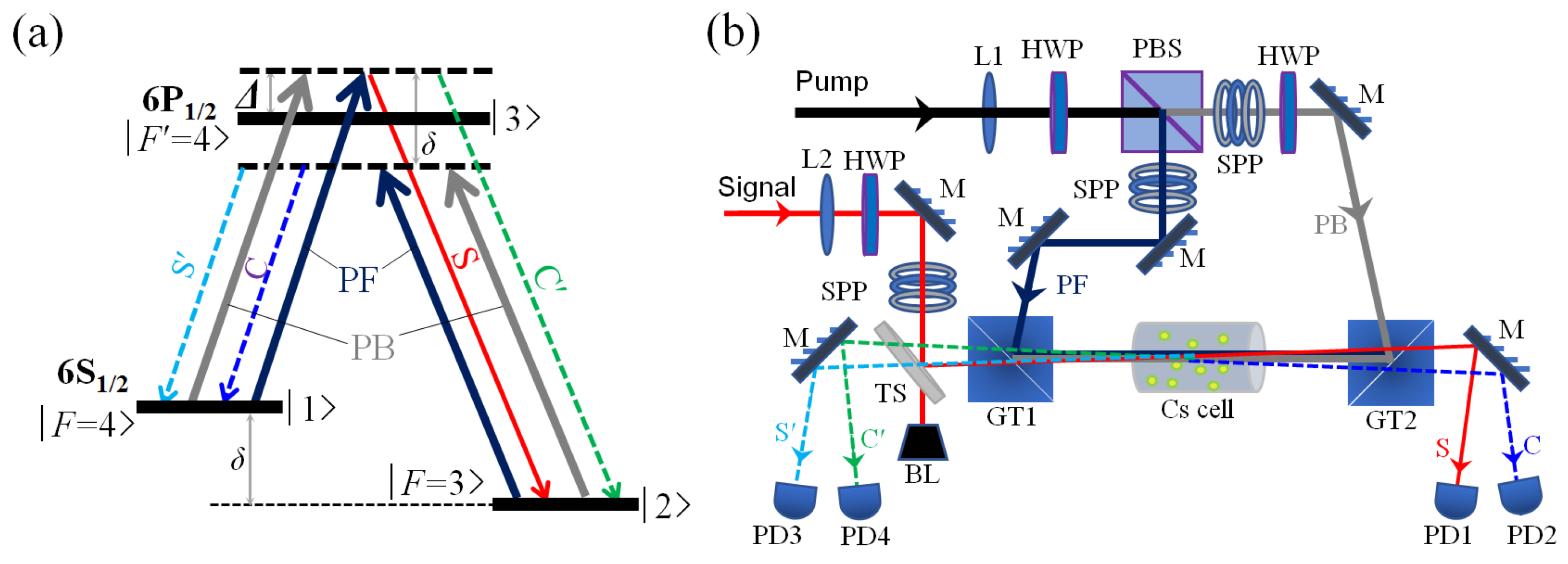
Figure 2.
(Color online) The normalized transmission spectra detected by PD1-PD4 versus signal detuning ΔS with different pump excitation: (a) only the forward pump PF (PPF=250 mW, PPB=0); (b) both PF and PB are present (PPF=250 mW, PPB=200 mW). The experimental parameters are: PS0=200 μW, Tcell=100 °C, and Δ=1.1 GHz.
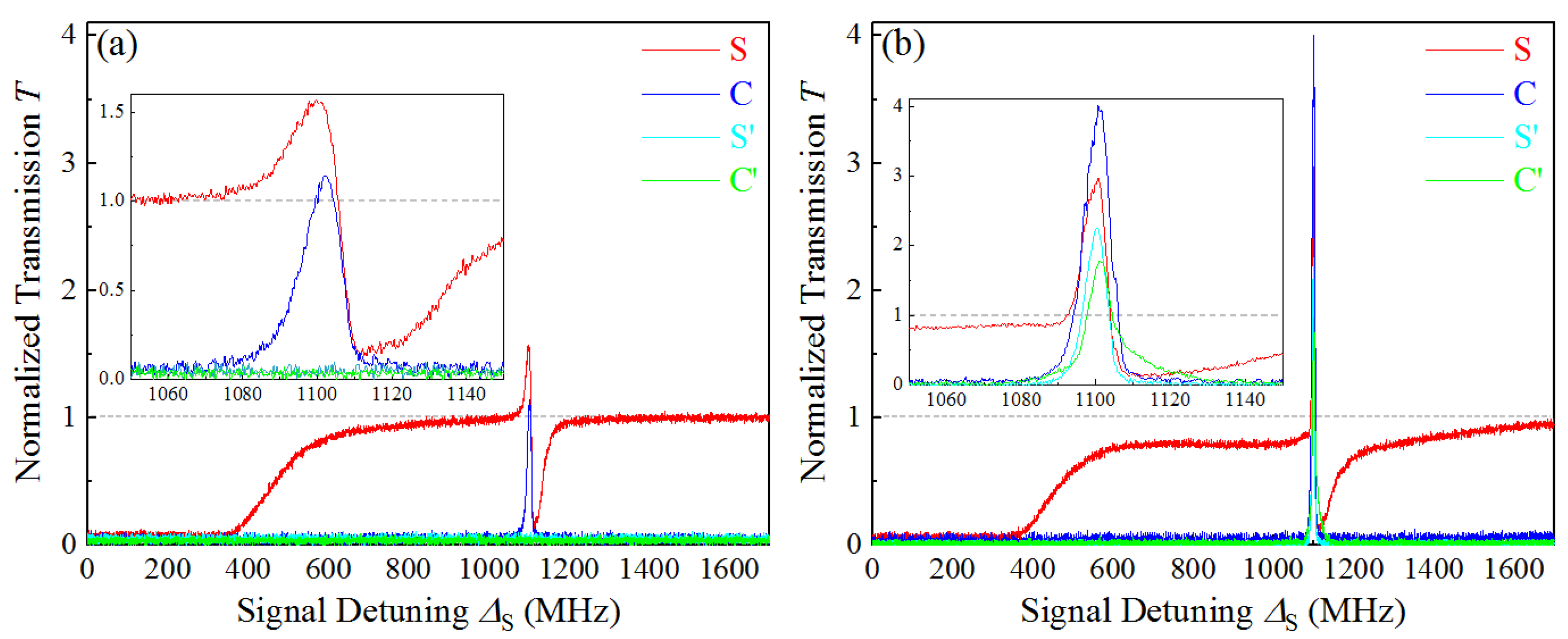
Figure 3.
The energy-level transition schemes (a1-a4) and corresponding phase-matching diagrams (b1-b4) of the multiple FWM interactions induced by the two counter-propagating pump fields. k is the wave vector of the beam in atomic medium.
Figure 3.
The energy-level transition schemes (a1-a4) and corresponding phase-matching diagrams (b1-b4) of the multiple FWM interactions induced by the two counter-propagating pump fields. k is the wave vector of the beam in atomic medium.
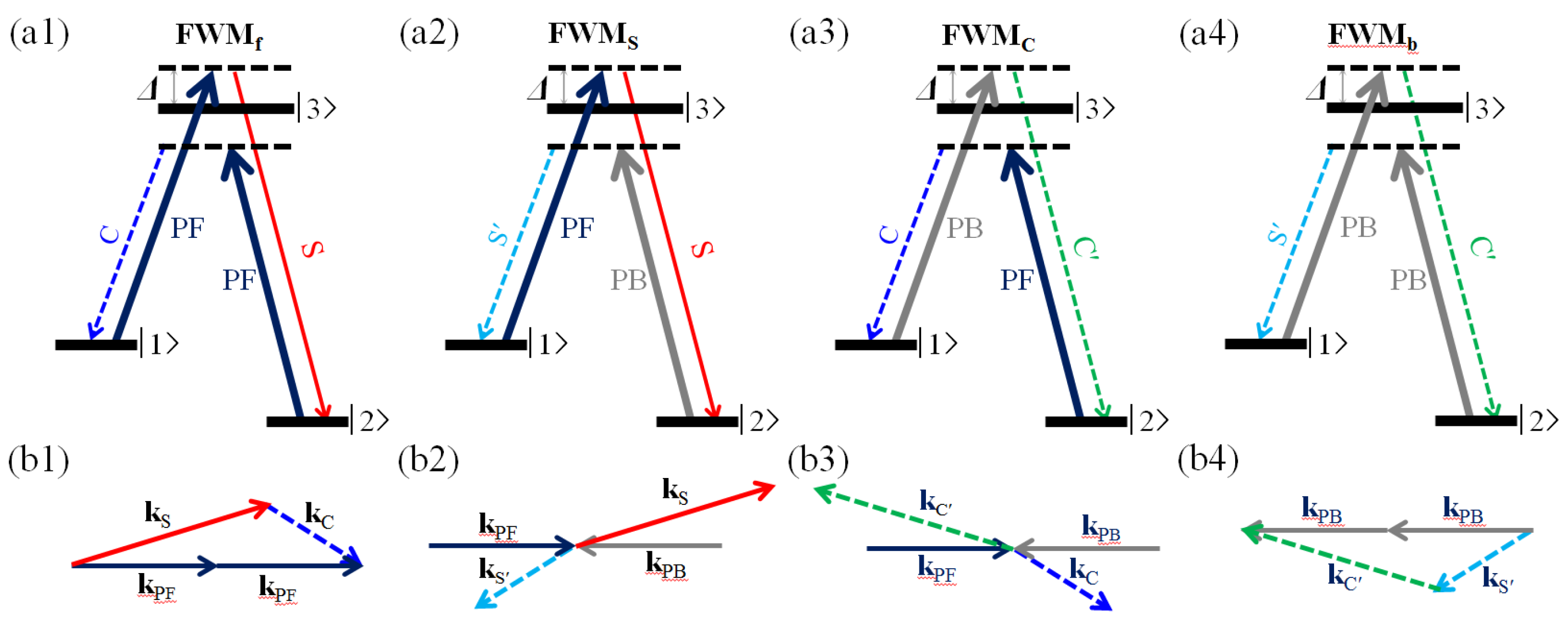
Figure 4.
The patterns of the (a) forward output beams and the (b) backward output beams captured by a camera when the OAM quantum numbers of input beams are: lS = 1, and lPF=lPB= 0. The single photon detuning is ΔS =Δ=1.1 GHz. The other parameters are same as in Figure 2.
Figure 4.
The patterns of the (a) forward output beams and the (b) backward output beams captured by a camera when the OAM quantum numbers of input beams are: lS = 1, and lPF=lPB= 0. The single photon detuning is ΔS =Δ=1.1 GHz. The other parameters are same as in Figure 2.
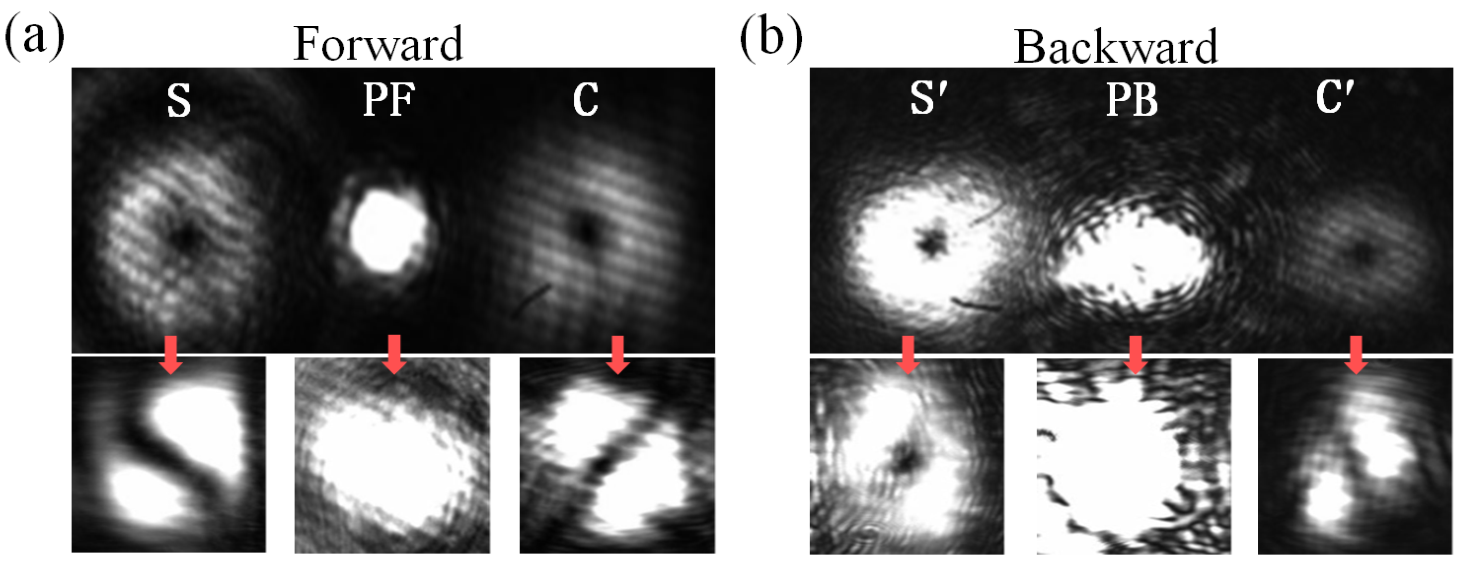
Figure 5.
The patterns of the forward and backward output beams when modulating the OAM quantum numbers of the pump beams: (a), (b) lPF = 1, and lS = lPB = 0; (c), (d) lPB = 1, and lS = lPF = 0. The other parameters are same as in Figure 4.
Figure 5.
The patterns of the forward and backward output beams when modulating the OAM quantum numbers of the pump beams: (a), (b) lPF = 1, and lS = lPB = 0; (c), (d) lPB = 1, and lS = lPF = 0. The other parameters are same as in Figure 4.
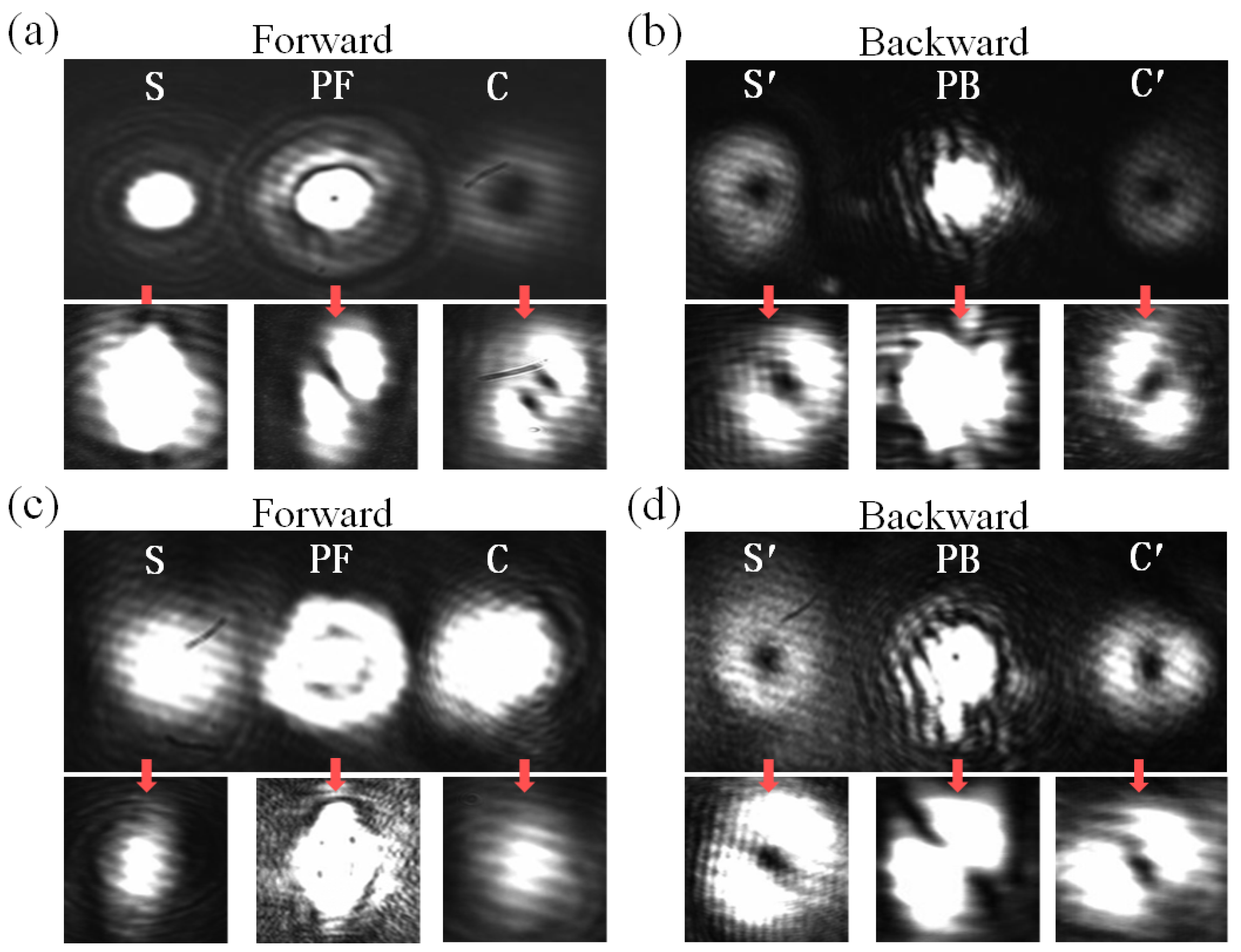
Figure 6.
Intensity patterns (a1-a4) and phase patterns (b1-b4) of the four output optical fields (ΩS(C) (z=0), ΩS′(C′) (z=L)) when lS =1and lPF = lPB =0.
Figure 6.
Intensity patterns (a1-a4) and phase patterns (b1-b4) of the four output optical fields (ΩS(C) (z=0), ΩS′(C′) (z=L)) when lS =1and lPF = lPB =0.
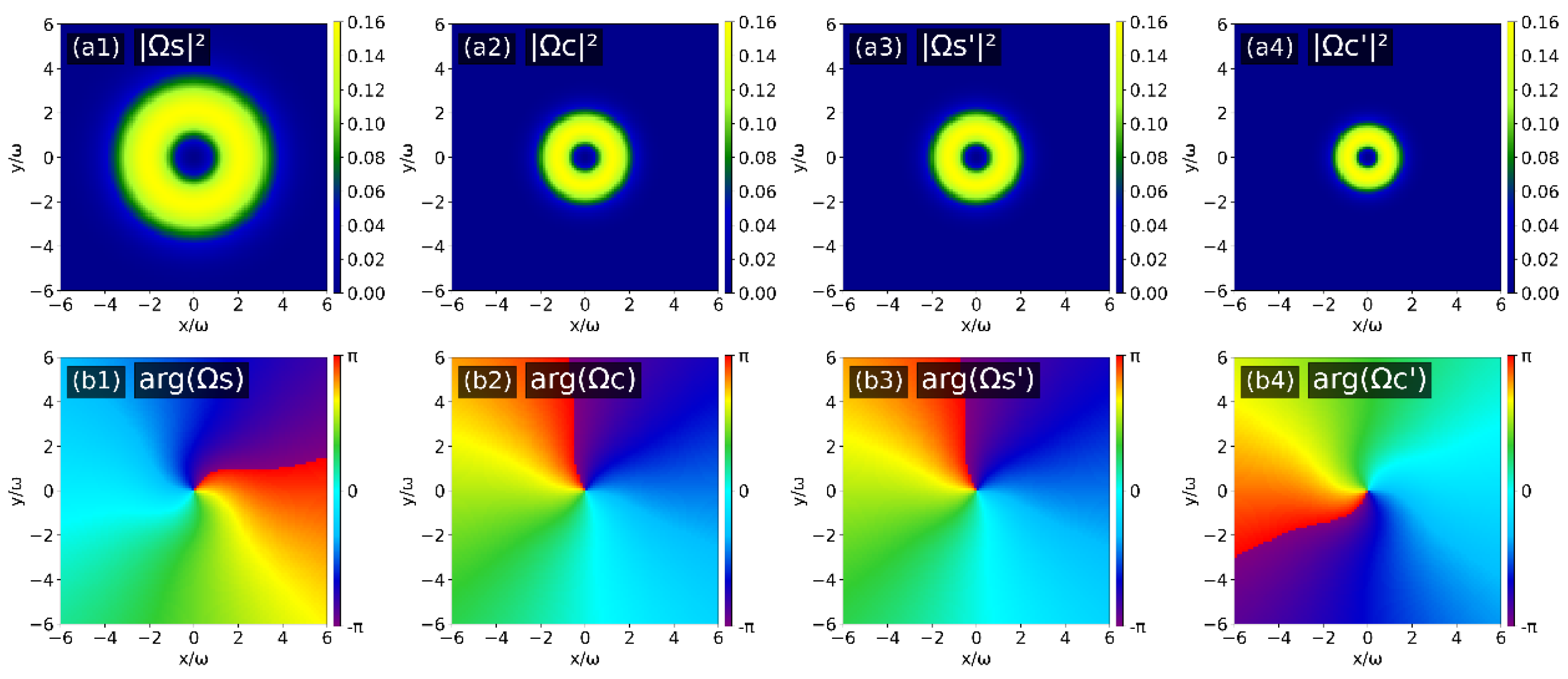
Figure 7.
Intensity patterns (a1-a4) and phase patterns (b1-b4) of the four output optical fields (ΩS(C) (z=0), ΩS′(C′) (z=L)) when lPF =1 and lS = lPB =0.
Figure 7.
Intensity patterns (a1-a4) and phase patterns (b1-b4) of the four output optical fields (ΩS(C) (z=0), ΩS′(C′) (z=L)) when lPF =1 and lS = lPB =0.
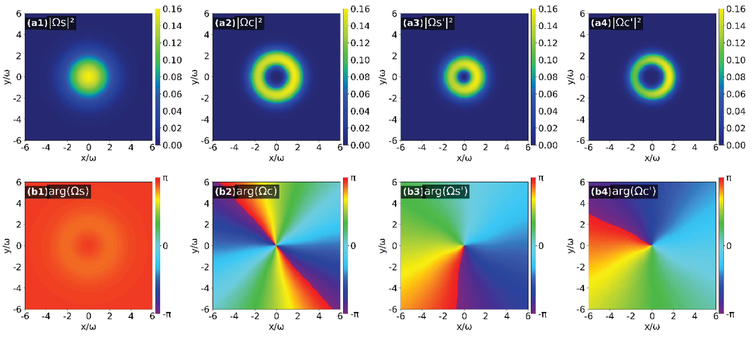
Figure 8.
Intensity patterns (a1-a4) and phase patterns (b1-b4) of the four output optical fields (ΩS(C) (z=0), ΩS′(C′) (z=L)) when lPB =1 and lS = lPF =0.
Figure 8.
Intensity patterns (a1-a4) and phase patterns (b1-b4) of the four output optical fields (ΩS(C) (z=0), ΩS′(C′) (z=L)) when lPB =1 and lS = lPF =0.
Disclaimer/Publisher’s Note: The statements, opinions and data contained in all publications are solely those of the individual author(s) and contributor(s) and not of MDPI and/or the editor(s). MDPI and/or the editor(s) disclaim responsibility for any injury to people or property resulting from any ideas, methods, instructions or products referred to in the content. |
© 2025 by the authors. Licensee MDPI, Basel, Switzerland. This article is an open access article distributed under the terms and conditions of the Creative Commons Attribution (CC BY) license (http://creativecommons.org/licenses/by/4.0/).
Copyright: This open access article is published under a Creative Commons CC BY 4.0 license, which permit the free download, distribution, and reuse, provided that the author and preprint are cited in any reuse.


