Submitted:
24 December 2025
Posted:
25 December 2025
You are already at the latest version
Abstract
This study presents the first atomistic modeling investigation of Additive Friction Stir Deposition (AFSD), providing detailed insights into thermomechanical and microstructural evolution at the nanoscale. Molecular dynamics simulations using the Large-scale Atomic/Molecular Massively Parallel Simulator (LAMMPS) were employed to capture the complex interplay of rotation, translation, and frictional heating during aluminum deposition. The aluminum system was modeled using an Embedded Atom Method potential with periodic boundary conditions, enabling realistic representation of material flow and layer formation. Comprehensive atomistic diagnostics revealed that severe plastic deformation is highly localized at the tool-substrate interface, with elevated shear strain concentrated beneath the rotating feedstock. Analysis of atomic coordination numbers demonstrated significant lattice distortion in the interfacial region, while dislocation structure characterization identified defect clustering associated with plastic strain accumulation. Voronoi tessellation-based analyses quantified heterogeneous atomic packing, free-volume generation, and cavity formation, correlating spatially with regions of intense deformation. These results show that AFSD promotes metallurgical bonding through confined interfacial mixing while preserving substrate integrity. The atomistic framework developed here establishes a foundation for understanding deformation mechanisms, optimizing process parameters, and predicting microstructural evolution in solid-state additive manufacturing, offering insights complementary to experimental observations at macroscopic scales.
Keywords:
additive friction stir deposition
; molecular dynamics simulation
; microstructural evolution
; severe plastic deformation
1. Introduction
Friction Stir Welding (FSW) emerged in the early 1990s as a solid state joining technique that uses frictional heat and mechanical stirring to bond materials without reaching their melting point. The process employs a rotating tool that generates localized heating through friction while applying severe plastic deformation to the workpiece [1,2,3,4,5,6]. This combination softens the material and creates a metallurgical bond between adjacent parts. FSW proved particularly effective for joining aluminum alloys that are difficult to weld using conventional fusion methods, avoiding issues such as porosity, hot cracking, and solidification defects. The success of FSW in producing high quality joints with minimal distortion and superior mechanical properties motivated researchers to explore extensions of the underlying principles to other manufacturing applications.
Additive Friction Stir Deposition (AFSD) represents a direct adaptation of FSW principles to additive manufacturing. Instead of joining two separate pieces, AFSD uses a rotating hollow tool to push a consumable feedstock rod onto a substrate, depositing material layer by layer. The rotating tool generates frictional heat at the interface while imposing severe plastic deformation on the softened feedstock. Material transfers from the feedstock to the substrate, building up three dimensional components through successive deposition passes. AFSD operates entirely in the solid state, avoiding the thermal gradients, residual stresses, and microstructural coarsening associated with fusion based additive techniques [7,8,9,10,11]. The process enables fabrication of large scale components from high strength aluminum alloys, titanium alloys, and other materials that are challenging to process using powder bed or directed energy deposition methods.
Industrial adoption of AFSD has grown rapidly, yet fundamental understanding of the process remains limited. Experimental characterization provides valuable data on temperature fields, deposition rates, and final microstructures, but direct observation of interfacial phenomena during processing is challenging [12,13,14,15]. The deformation zone beneath the tool experiences extreme conditions including strain rates exceeding 103 per second, temperatures approaching the solidus, and complex three dimensional material flow. Conventional characterization techniques cannot resolve the atomic scale mechanisms governing material transfer, interfacial bonding, and defect formation during deposition. Macroscopic models based on continuum mechanics provide useful predictions of temperature and stress fields but lack the resolution to capture dislocation dynamics, grain boundary evolution, and local structural transformations that determine final material properties.
Atomistic modeling offers a direct approach to investigate deformation mechanisms at length and time scales inaccessible to experimental methods. Molecular dynamics simulations explicitly track individual atoms, computing forces from interatomic potentials and integrating equations of motion to evolve the system. This approach naturally captures plastic deformation through dislocation nucleation and motion, structural phase transformations, and interfacial phenomena without imposed constitutive assumptions. Atomic scale resolution enables quantification of local strain fields, coordination environments, and defect structures throughout the deformation process. Recent advances in computational power and interatomic potential development have made it feasible to simulate systems containing millions of atoms under realistic processing conditions, bridging the gap between quantum mechanical calculations and continuum models.
This work presents the first atomistic investigation of AFSD using molecular dynamics simulations. The study focuses on aluminum deposition to establish baseline understanding of fundamental mechanisms. Simulations reproduce the essential features of AFSD including tool rotation, feedstock feeding, frictional heating, and material deposition. Detailed analysis of atomic trajectories, strain fields, coordination numbers, and defect structures reveals how severe plastic deformation at the tool substrate interface enables material transfer and metallurgical bonding. Results provide direct evidence of deformation localization, dislocation activity, and free volume generation that underlie successful solid state deposition. The atomistic framework developed here establishes a foundation for predicting microstructural evolution and optimizing process parameters in AFSD and related solid state manufacturing technologies.
2. Methodology
An atomistic simulation framework was developed to study the Additive Friction Stir Deposition (AFSD) process show in Figure 1 using the Large-scale Atomic/Molecular Massively Parallel Simulator (LAMMPS) [16] depicted in Figure 2. The simulations were carried out in three dimensions under metal units with periodic boundary conditions in the lateral directions and a free surface along the build direction, enabling realistic material flow and deposition. Aluminum was modeled using an FCC lattice with a lattice constant of 4.05 Å, and atomic interactions were described through an Embedded Atom Method (EAM) alloy potential suitable for aluminum systems. The computational domain consisted of a rigid substrate and a cylindrical feedstock positioned above it, representing the consumable rod used in AFSD. The substrate occupied the lower region of the simulation box, while the feedstock was initialized as a vertical cylinder extending above the substrate.
To capture the mechanical and thermal behavior during deposition, atoms were categorized into substrate, feedstock, and deposited material based on their type, with dynamic group definitions used to track oxide layers, core tracer atoms, and the evolving interface region. The bottommost substrate layers were fully constrained to emulate a rigid backing plate, while the remaining substrate atoms were allowed to respond dynamically. Initial velocities corresponding to 300 K were assigned to all atoms except the fixed boundary. Temperature control was applied using Nosé–Hoover thermostats, with separate thermal ramps for the substrate and feedstock to reproduce differential heating during processing. A timestep of 1 fs was used to ensure numerical stability given the high strain rates and temperatures involved.
The AFSD process was emulated by superimposing rotational, translational, and downward feed motions on the feedstock atoms. Rotation corresponding to 300 rpm was imposed via body forces derived from angular velocity, while linear traverse and feed velocities controlled lateral movement and material deposition, respectively. Frictional heating at the tool–substrate interface was modeled by dynamically identifying atoms within a predefined contact zone and applying a localized heat flux when contact occurred. Deposition was represented by converting feedstock atoms to deposited material once they crossed a specified height threshold, allowing continuous buildup of material over multiple deposition cycles. This conversion was performed iteratively to mimic steady-state deposition.
Extensive atomistic diagnostics were employed to analyze the evolving microstructure and thermomechanical response. Per-atom quantities such as potential energy, kinetic energy, stress tensor components, coordination number, centro-symmetry parameter, common neighbor analysis, displacement, and Voronoi volumes were computed throughout the simulation. Spatially resolved temperature fields were obtained using three-dimensional binning, and time-averaged quantities were recorded to assess steady-state behavior. Multiple dump files tracked oxide evolution, tracer motion, and interface characteristics. Following active deposition, a controlled cooldown stage using Langevin dynamics reduced the system temperature to ambient conditions. The final atomic configuration was written to a data file, and global metrics such as atom counts, average coordination number, and centro-symmetry parameter were evaluated to quantify the final deposited structure and its structural integrity.
3. Results and Discussion
3.1. Atomic Strain analysis
The localized shear strain observed beneath the feedstock arises from the combined effects of tool rotation, axial feeding, and frictional heating, as implemented in the molecular dynamics model. The local atomic shear strain is computed from the deviatoric component of the strain tensor is computed using Equation 1.
where denotes the deviatoric strain tensor. Figure 3 shows that elevated values of are concentrated near the tool–substrate interface and directly beneath the rotating feedstock. The concentration of strain at the tool–substrate interface indicates the formation of a severe plastic deformation zone, which is a prerequisite for metallurgical bonding and material transfer in AFSD. The limited penetration of high shear strain into the bulk substrate suggests that deformation is efficiently confined, reducing excessive subsurface damage while promoting interfacial mixing. These atomistic observations provide direct evidence of the mechanisms responsible for layer formation in AFSD, complementing experimental interpretations based on macroscopic force and temperature measurements.
3.2. Local Atomic Coordination Analysis
Figure 4 shows the spatial evolution of the atomic coordination number during tool engagement. The local coordination number of atom is defined using Equation 2.
where is the interatomic distance is the cutoff radius and is the Heaviside function. Atoms in the undeformed regions of the substrate and feedstock maintain coordination values close to those of the initial crystalline lattice. A pronounced reduction in is observed at the tool–substrate interface, as seen in Figure 4(a–c). The three-dimensional view (Figure 4(d)) confirms that coordination loss is spatially confined to a narrow interfacial zone beneath the tool.
3.3. Dislocation Structures Analysis
Figure 5 shows the spatial distribution of atomic clusters and defect structures formed during AFSD. Clusters are identified by grouping atoms based on local structural similarity and connectivity. The observed clustering behavior is associated with the accumulation and interaction of dislocations generated by severe plastic deformation. As deformation progresses, dislocations nucleate and interact, leading to the formation of stable defect structures. The local defect density can be qualitatively related to plastic strain accumulation using Equation 3.
where is the local plastic shear strain and is the Burgers vector magnitude. The confinement of defect clusters to the interfacial region suggests that AFSD promotes localized strain accommodation through dislocation activity, enabling material mixing and bonding while limiting damage to the surrounding substrate.
3.4. Voronoi-Based Local Atomic Volume
Figure 6 shows the spatial distribution of local atomic environments quantified using Voronoi tessellation. Each atom is assigned a Voronoi polyhedron, whose volume and face count characterize its local neighborhood. The effective coordination number can be expressed using Equation 4.
where is the number of faces of the Voronoi polyhedron associated with atom . Most atoms in the bulk substrate and feedstock exhibit uniform Voronoi coordination consistent with the initial crystalline structure. Localized deviations in Voronoi coordination are observed beneath the rotating feedstock, as seen in Figure 6(a–c), indicating heterogeneous atomic packing in the interfacial region.
The localized increase and spread in atomic volume reflect dilation and packing inefficiency caused by intense shear deformation and atomic rearrangement as depicted in Figure 7. Variations in atomic volume correlate spatially with regions of high displacement magnitude and reduced coordination, indicating that plastic flow in AFSD is accompanied by transient local free-volume generation. This localized volumetric heterogeneity facilitates atomic mobility and interfacial mixing while preserving dense packing in the surrounding substrate. A qualitative relationship between atomic volume and deformation can be expressed using Equation 5.
Figure 8 presents the cavity radius field computed from Voronoi tessellation. For each atom , the cavity radius is defined as the radius of the largest empty sphere that fits within the local Voronoi polyhedron computed using Equation 8.
where denotes the Voronoi cell of atom . The results show that most atoms in the bulk substrate exhibit small cavity radii characteristic of dense crystalline packing. A localized increase in is observed beneath the feedstock and at the interface (Figure 8(a–c)), with the three-dimensional view (Figure 8(d)) confirming that free-volume accumulation is confined to the active deformation zone.
4. Conclusion
This study presents the first atomistic modeling investigation of Additive Friction Stir Deposition using molecular dynamics simulations. The computational framework successfully captured the essential thermomechanical processes during aluminum deposition, including tool rotation, frictional heating, and severe plastic deformation at the tool substrate interface. Atomic scale analysis revealed that shear strain localizes beneath the rotating feedstock, creating a confined deformation zone that facilitates material transfer while preserving the integrity of the surrounding substrate.
Detailed characterization of microstructural evolution demonstrated significant reduction in atomic coordination numbers at the interface, indicating lattice distortion and disorder induced by intense plastic flow. Dislocation structure analysis identified defect clustering in regions experiencing severe deformation, consistent with the high strain rates imposed during processing. Voronoi tessellation based metrics quantified heterogeneous atomic packing, free volume generation, and cavity formation, all spatially correlated with the active deformation zone. These findings confirm that AFSD achieves metallurgical bonding through localized interfacial mixing driven by severe plastic deformation under solid state conditions.
The atomistic framework developed here provides a foundation for understanding deformation mechanisms in AFSD at length and time scales inaccessible to experimental characterization. Future work will extend these simulations to investigate multi-layer deposition, thermal cycling effects, and processing of alternative alloy systems. Integration of atomistic insights with continuum scale models will enable optimization of process parameters for improved mechanical properties and deposition efficiency in solid state additive manufacturing applications.
References
- Du, Y.; Mukherjee, T.; Mitra, P.; DebRoy, T. Machine learning based hierarchy of causative variables for tool failure in friction stir welding. Acta Materialia 2020, 192, 67–77. [Google Scholar] [CrossRef]
- Chadha, U.; Selvaraj, S.K.; Gunreddy, N.; Sanjay Babu, S.; Mishra, S.; Padala, D.; Shashank, M.; Mathew, R.M.; Kishore, S.R.; Panigrahi, S.; Nagalakshmi, R. A survey of machine learning in friction stir welding, including unresolved issues and future research directions. Material Design & Processing Communications 2022, 2022, 2568347. [Google Scholar] [CrossRef]
- Du, Y.; Mukherjee, T.; DebRoy, T. Conditions for void formation in friction stir welding from machine learning. npj Computational Materials 2019, 5, 68. [Google Scholar] [CrossRef]
- Maleki, E. Artificial neural networks application for modeling of friction stir welding effects on mechanical properties of 7075-T6 aluminum alloy. IOP Conference Series: Materials Science and Engineering, 2015, November; IOP Publishing; Vol. 103, p. 012034. [Google Scholar]
- Kulkarni, N.; Mishra, R.S.; Yuan, W. Friction stir welding of dissimilar alloys and materials; Butterworth-Heinemann, 2015. [Google Scholar]
- Soni, V.; Menchaca, R.L.; Davis, D.; Kumar, N.N.; Gonzalez, M.; Awasthi, P.; Haridas, R.S.; Loukus, A.; Weiss, D.; Mishra, R.S.; Vasudevan, V.K. Process-specific design strategy enables exceptional as-deposited strength-ductility synergy in novel Al–Ce alloys via additive friction stir deposition (AFSD). Journal of Materials Research and Technology 2025, 35, 1889–1900. [Google Scholar] [CrossRef]
- Sharma, A.; Jain, R.; Agrawal, P.; Mukherjee, S.; Gumaste, A.; Davis, D.F.; Haridas, R.S.; Mishra, R.S. Enhanced thermal stability in additive friction stir deposited ODS IN9052 Al alloy. Acta Materialia 2024, 279, 120284. [Google Scholar] [CrossRef]
- Yu, H.Z.; Mishra, R.S. Additive friction stir deposition: a deformation processing route to metal additive manufacturing. Materials Research Letters 2021, 9, 71–83. [Google Scholar] [CrossRef]
- Korgancı, M.; Bozkurt, Y. Recent developments in additive friction stir deposition (AFSD). J. Mater. Res. Technol 2024, 30, 4572–4583. [Google Scholar] [CrossRef]
- Zhang, X.; Li, Y.; Zhu, S.; Han, H.; Chen, T.; Zhou, Y.; Chen, L. Microstructure and mechanical properties of AFSD-formed 6061-7075 dissimilar aluminum alloys. Journal of Alloys and Compounds 2025, 182894. [CrossRef]
- Zhu, N.; Hickok, T.; Fraser, K.A.; Yu, D.; Chen, Y.; An, K.; Brewer, L.N.; Allison, P.G.; Jordon, J.B. Neutron diffraction analysis of residual stress distribution in the lubricant-free TR-AFSD AA7075 repair coupled with SPH simulations. Journal of Advanced Joining Processes 2025, 11, 100283. [Google Scholar] [CrossRef]
- Dong, X.; Zhou, M.; Geng, Y.; Han, Y.; Lei, Z.; Chen, G.; Shi, Q. Recent advances in additive friction stir deposition: a critical review. Materials 2024, 17, 5205. [Google Scholar] [CrossRef] [PubMed]
- Wen, Q.; Wan, L.; Zhang, Z. Interfacial Bonding Mechanism of Al–Fe Dissimilar AFSD Cladding Components. Metallurgical and Materials Transactions A 2025, 1–13. [Google Scholar] [CrossRef]
- Shao, J.; Samaei, A.; Xue, T.; Xie, X.; Guo, S.; Cao, J.; MacDonald, E.; Gan, Z. Additive friction stir deposition of metallic materials: Process, structure and properties. Materials & Design 2023, 234, 112356. [Google Scholar] [CrossRef]
- Robinson, T.W.; Williams, M.B.; Rao, H.M.; Kinser, R.P.; Allison, P.G.; Jordon, J.B. Microstructural and mechanical properties of a solid-state additive manufactured magnesium alloy. Journal of Manufacturing Science and Engineering 2022, 144, 061013. [Google Scholar] [CrossRef]
- Thompson, A. P.; Aktulga, H. M.; Berger, R.; Bolintineanu, D. S.; Brown, W. M.; Crozier, P. S.; in 't Veld, P. J.; Kohlmeyer, A.; Moore, S. G.; Nguyen, T. D.; Shan, R.; Stevens, M. J.; Tranchida, J.; Trott, C.; Plimpton, S. J. LAMMPS - a flexible simulation tool for particle-based materials modeling at the atomic, meso, and continuum scales. Comp Phys Comm 2022, 271, 10817. [Google Scholar] [CrossRef]
Figure 1.
Schematic illustration of the Additive Friction Stir Deposition (AFSD) process. A rotating hollow tool drives the feedstock downward onto the substrate, generating frictional heat and severe plastic deformation. The softened material is deposited layer by layer behind the tool, forming consolidated deposited layers metallurgically bonded to the substrate.
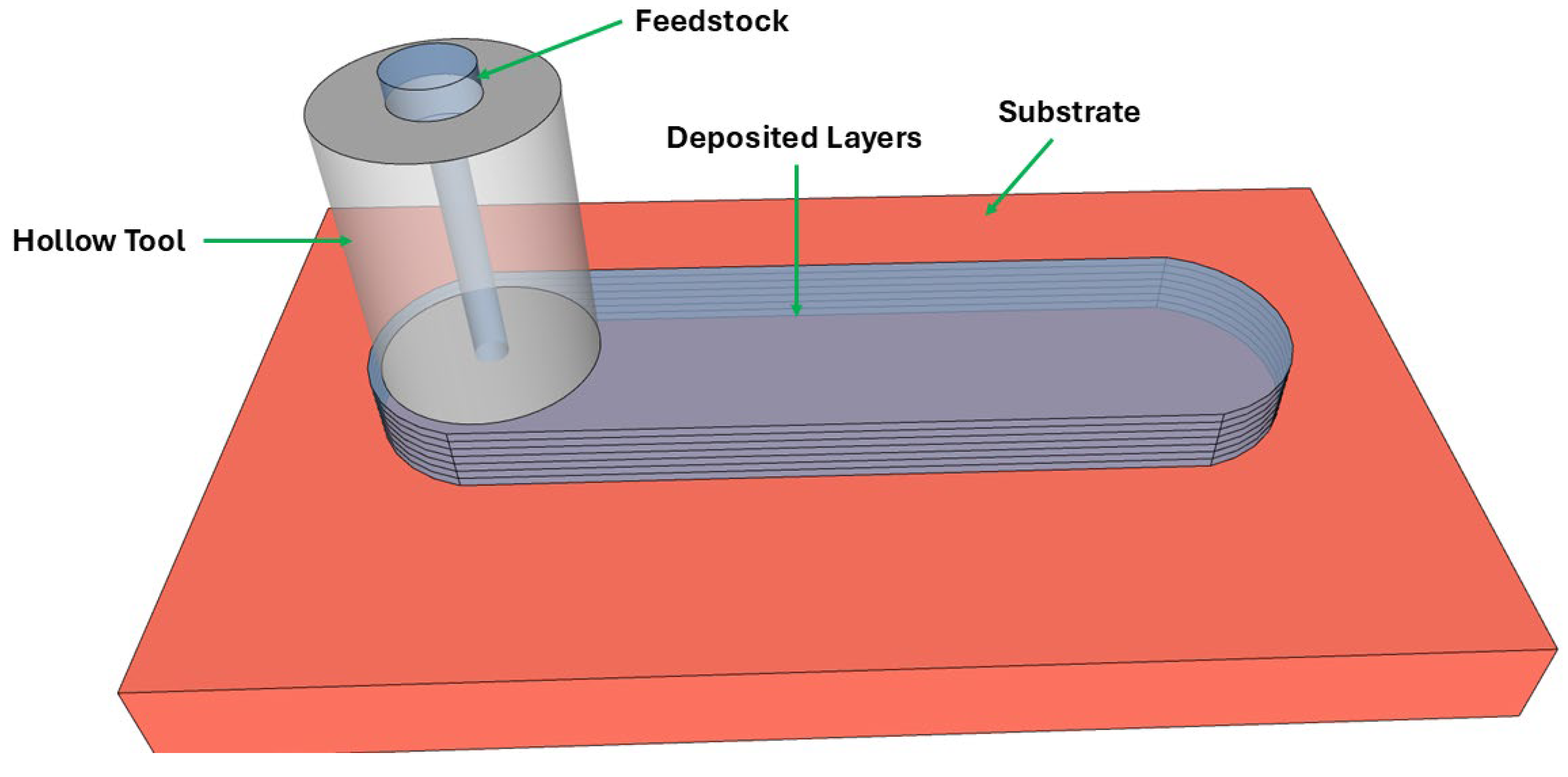
Figure 2.
Atomistic views of the AFSD simulation showing the aluminum substrate (red), cylindrical feedstock (blue), and interfacial contact atoms (yellow). Top, side, oblique, and perspective views illustrate initial alignment, tool engagement, and three-dimensional geometry of the deposition process.
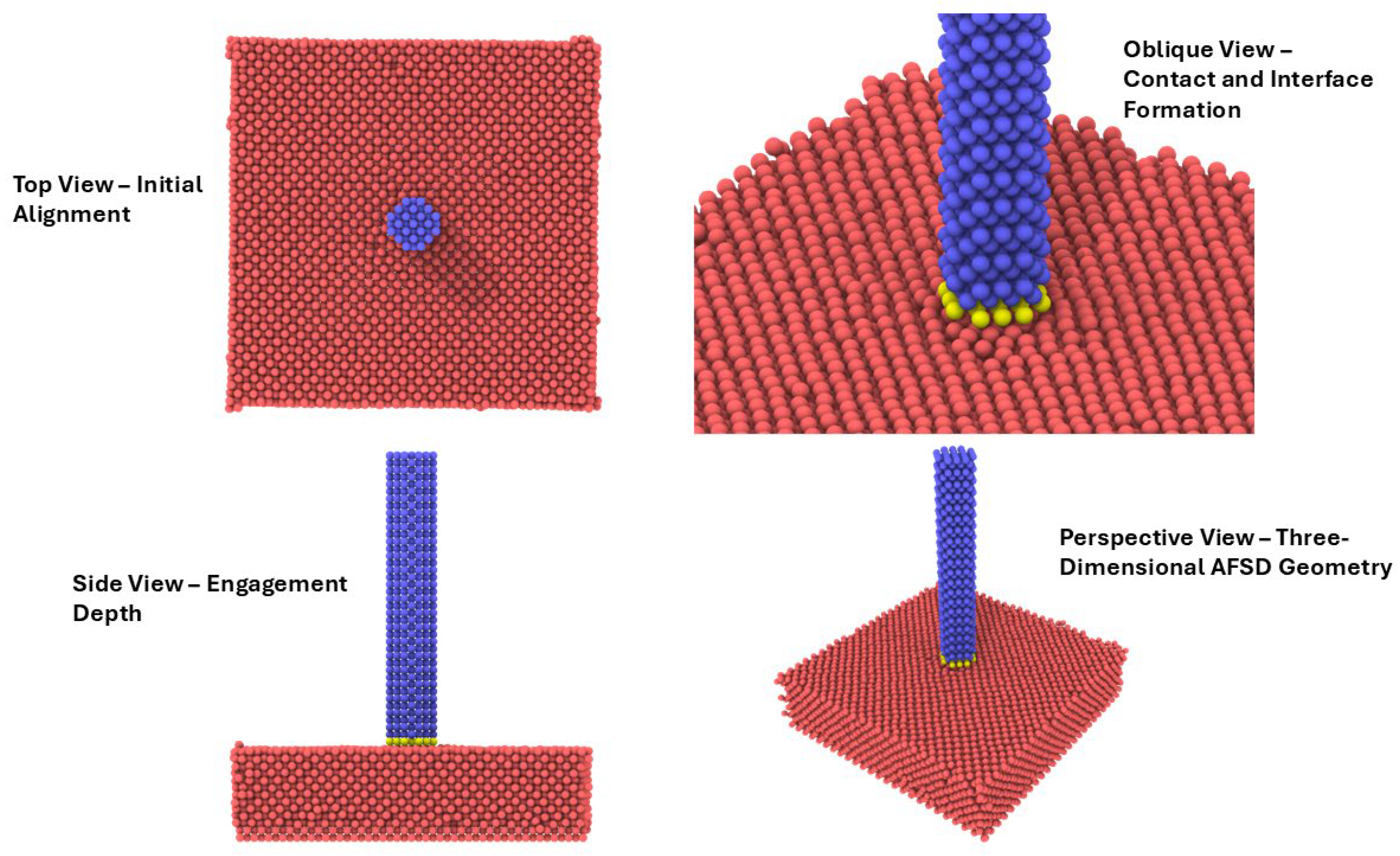
Figure 3.
Spatial distribution of atomic shear strain during the early stages of additive friction stir deposition (AFSD), visualized from molecular dynamics simulations. The aluminum substrate is shown together with the cylindrical feedstock, and atoms are colored according to the local atomic shear strain. Four complementary views are presented: (a) top view highlighting the radial distribution of strain beneath the tool, (b) oblique view emphasizing strain localization at the tool–substrate interface, (c) side view illustrating strain penetration into the substrate and feedstock, and (d) three-dimensional perspective view of the evolving deformation field. Elevated shear strain is concentrated near the interface and beneath the rotating feedstock, indicating the onset of severe plastic deformation and interfacial mixing that precedes material deposition.
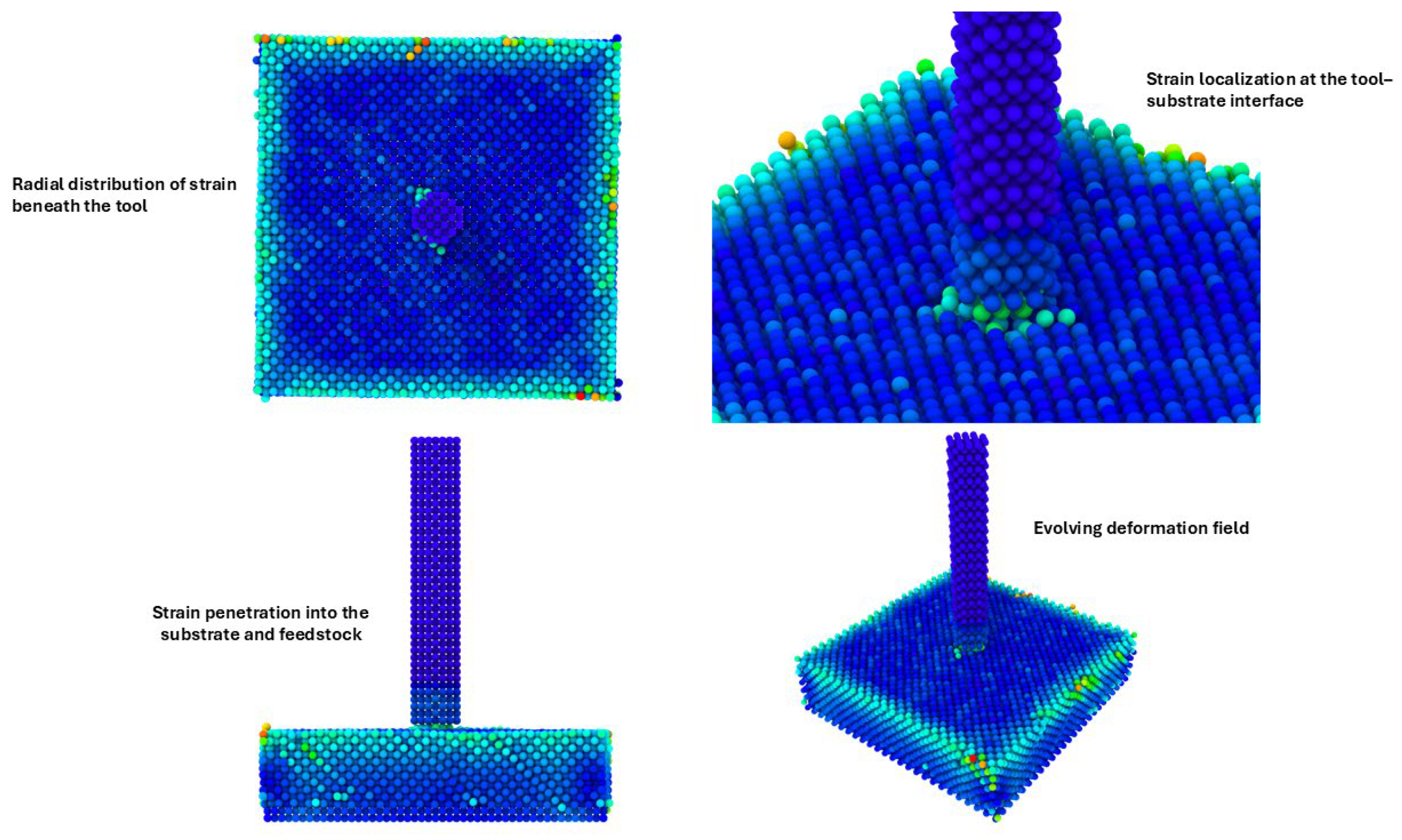
Figure 4.
Atomic coordination number distribution during tool–substrate interaction in additive friction stir deposition (AFSD), obtained from molecular dynamics simulations. Atoms are colored according to their local coordination number. Four views are shown: (a) top view illustrating spatial variations in coordination beneath the tool footprint, (b) oblique view highlighting coordination changes at the feedstock–substrate interface, (c) side view showing coordination gradients within the substrate and feedstock, and (d) three-dimensional perspective view of the evolving atomic structure. Regions of reduced coordination are concentrated near the tool–substrate interface, indicating local lattice distortion and disorder associated with severe plastic deformation and material mixing.
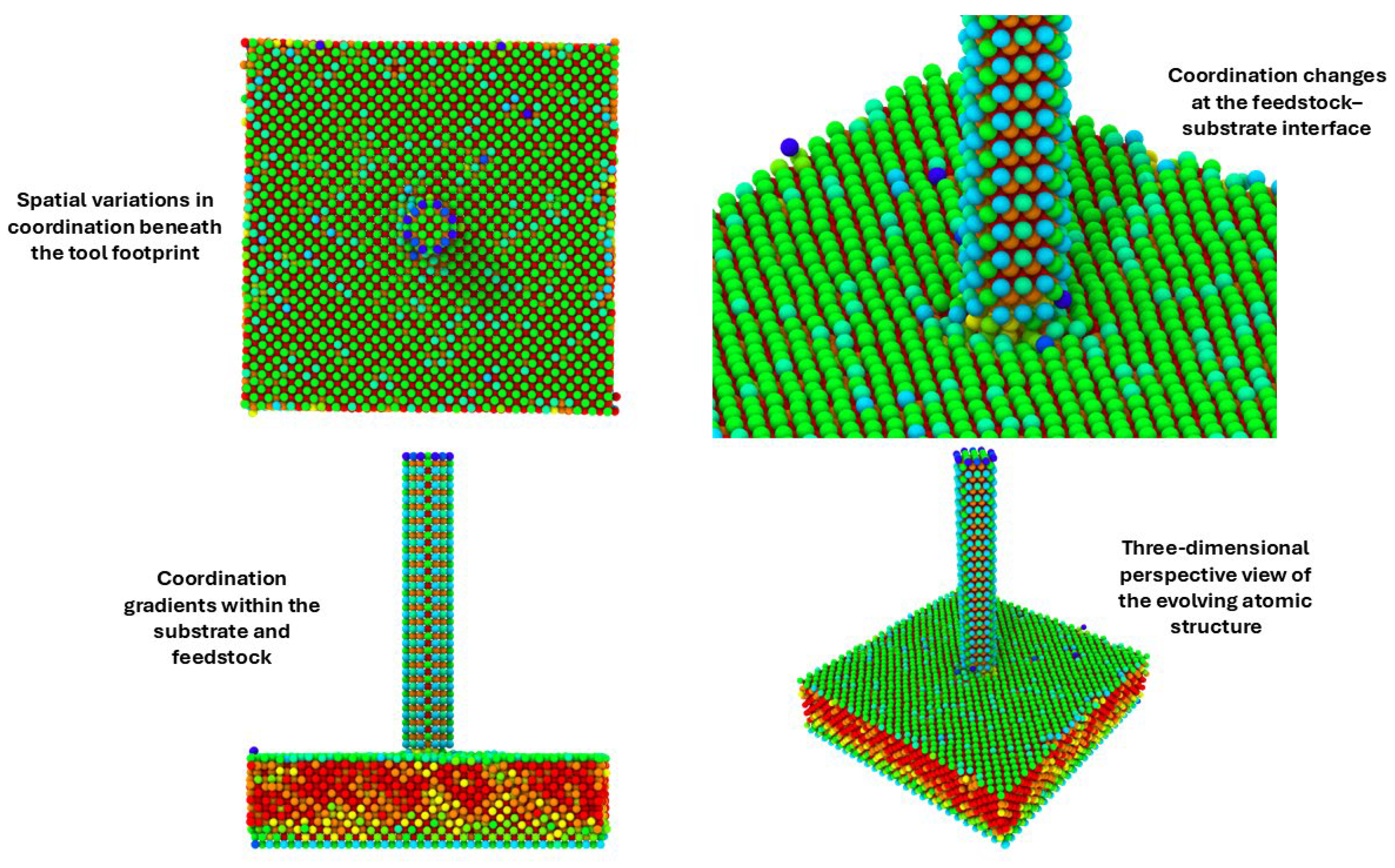
Figure 5.
Atomic cluster and dislocation structure during AFSD at an advanced stage of tool engagement. Atoms are colored by cluster membership, highlighting regions of defect aggregation and structural rearrangement. Views include (a) top, (b) oblique, (c) side, and (d) three-dimensional perspective representations. Defect clusters are concentrated near the tool–substrate interface and within the upper substrate region beneath the feedstock.
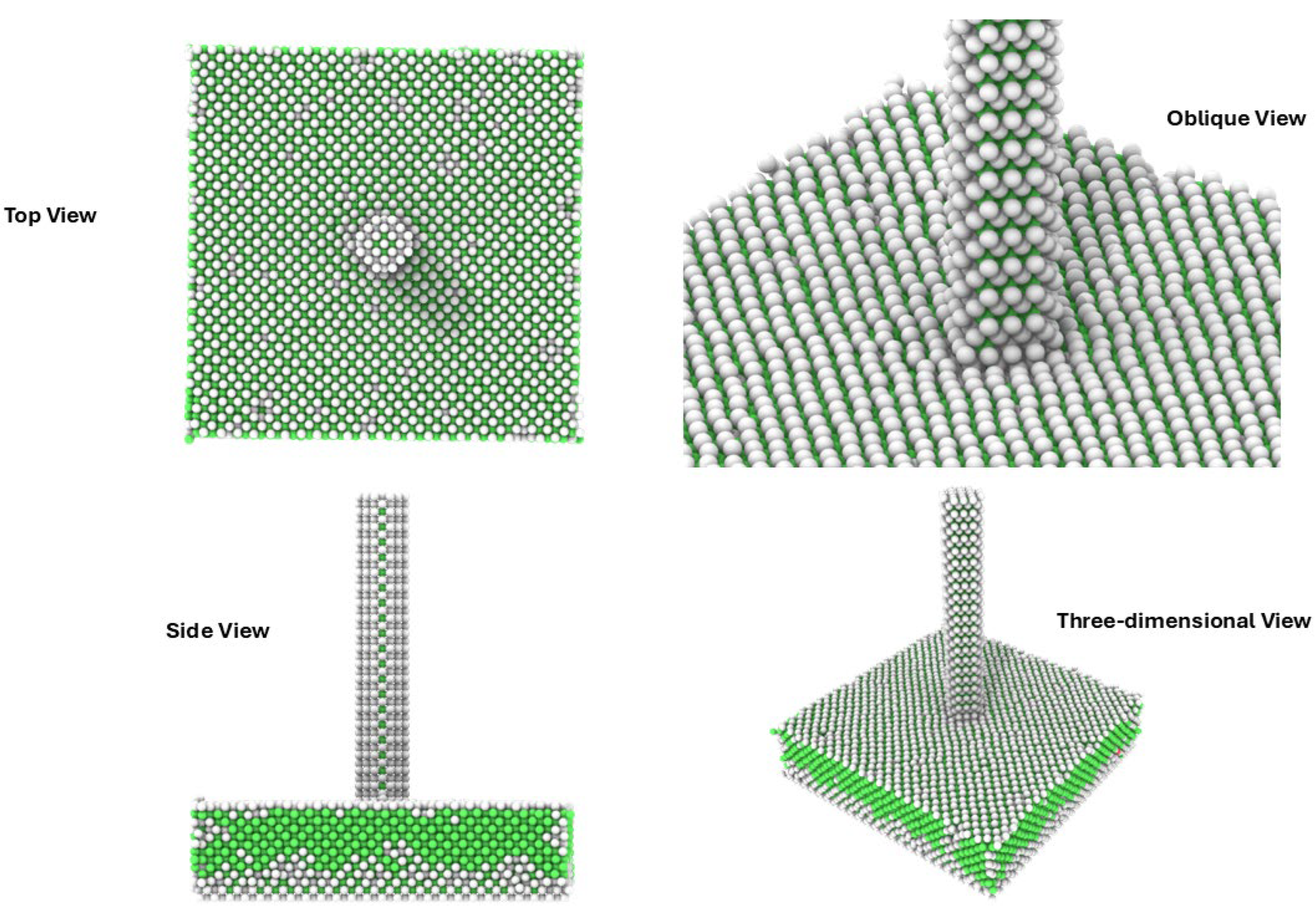
Figure 6.
Voronoi-based local atomic coordination distribution during AFSD at an advanced stage of tool engagement. Atoms are colored according to their Voronoi-derived coordination environment, shown in (a) top, (b) oblique, (c) side, and (d) three-dimensional perspective views. Variations in coordination are localized near the tool–substrate interface, indicating heterogeneous atomic environments induced by severe plastic deformation.
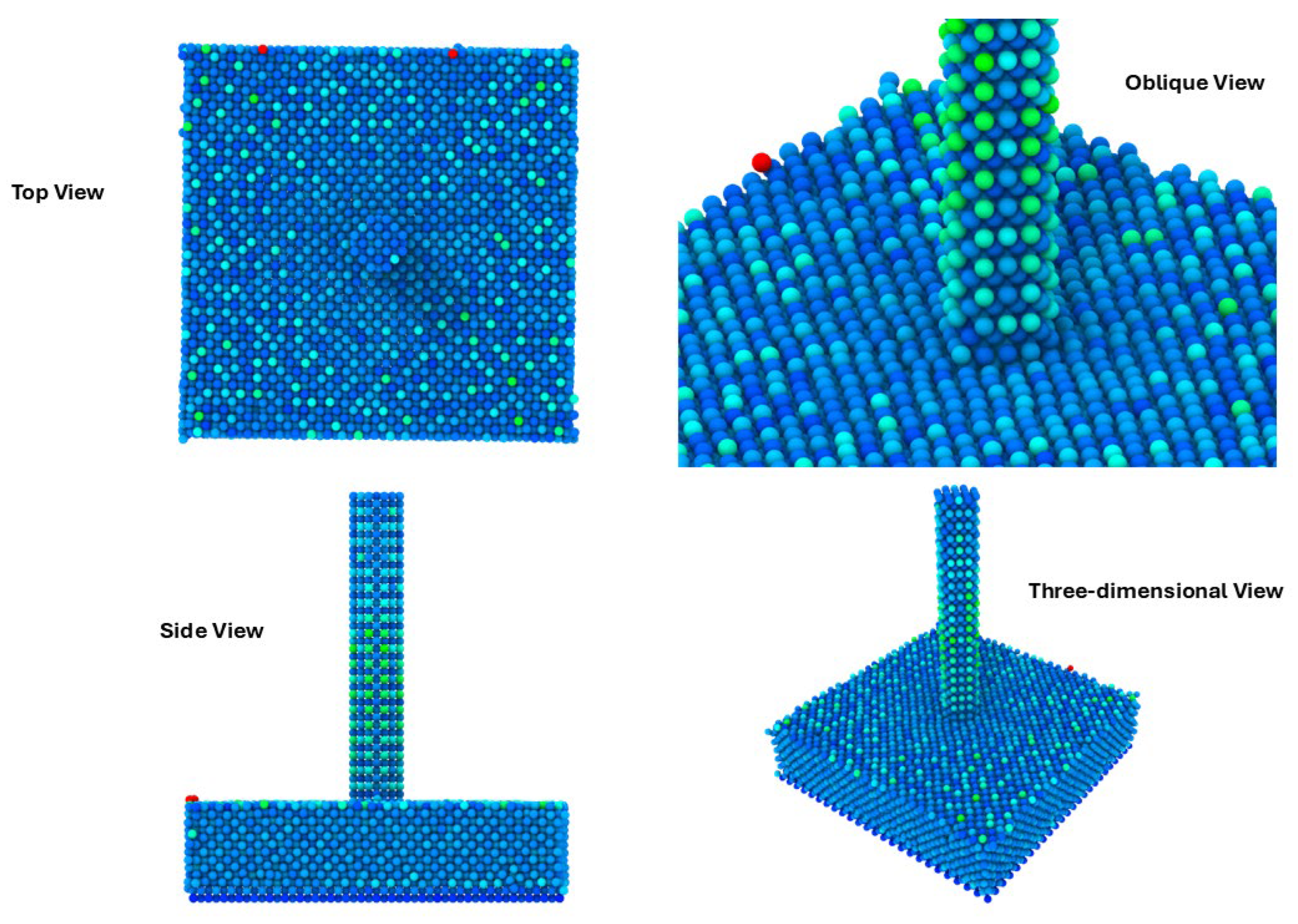
Figure 7.
Atomic volume distribution during AFSD at an advanced stage of tool engagement. Atoms are colored according to their local atomic (Voronoi) volume, shown in (a) top, (b) oblique, (c) side, and (d) three-dimensional perspective views. Localized variations in atomic volume are observed beneath the rotating feedstock and at the tool–substrate interface, indicating heterogeneous atomic packing induced by severe plastic deformation.
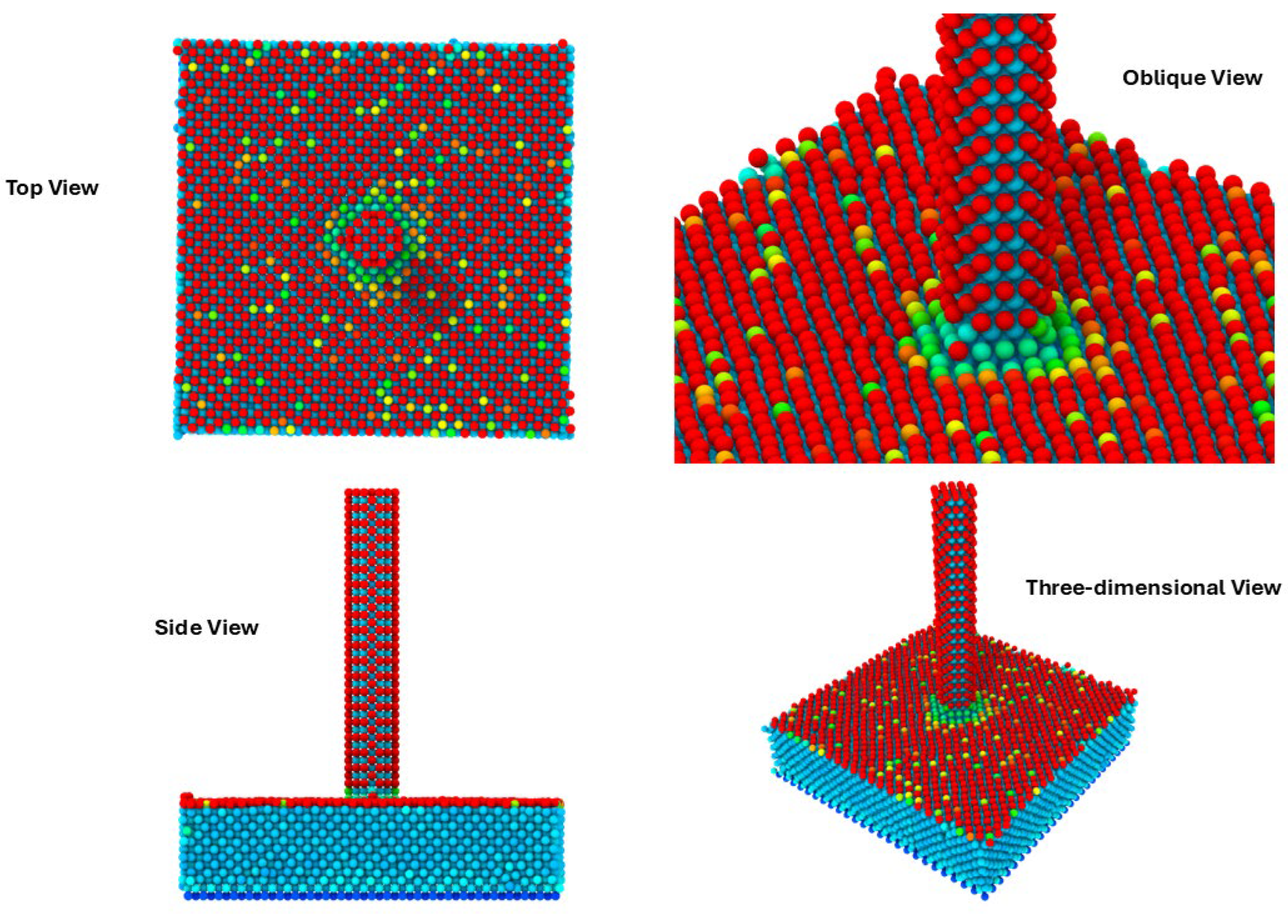
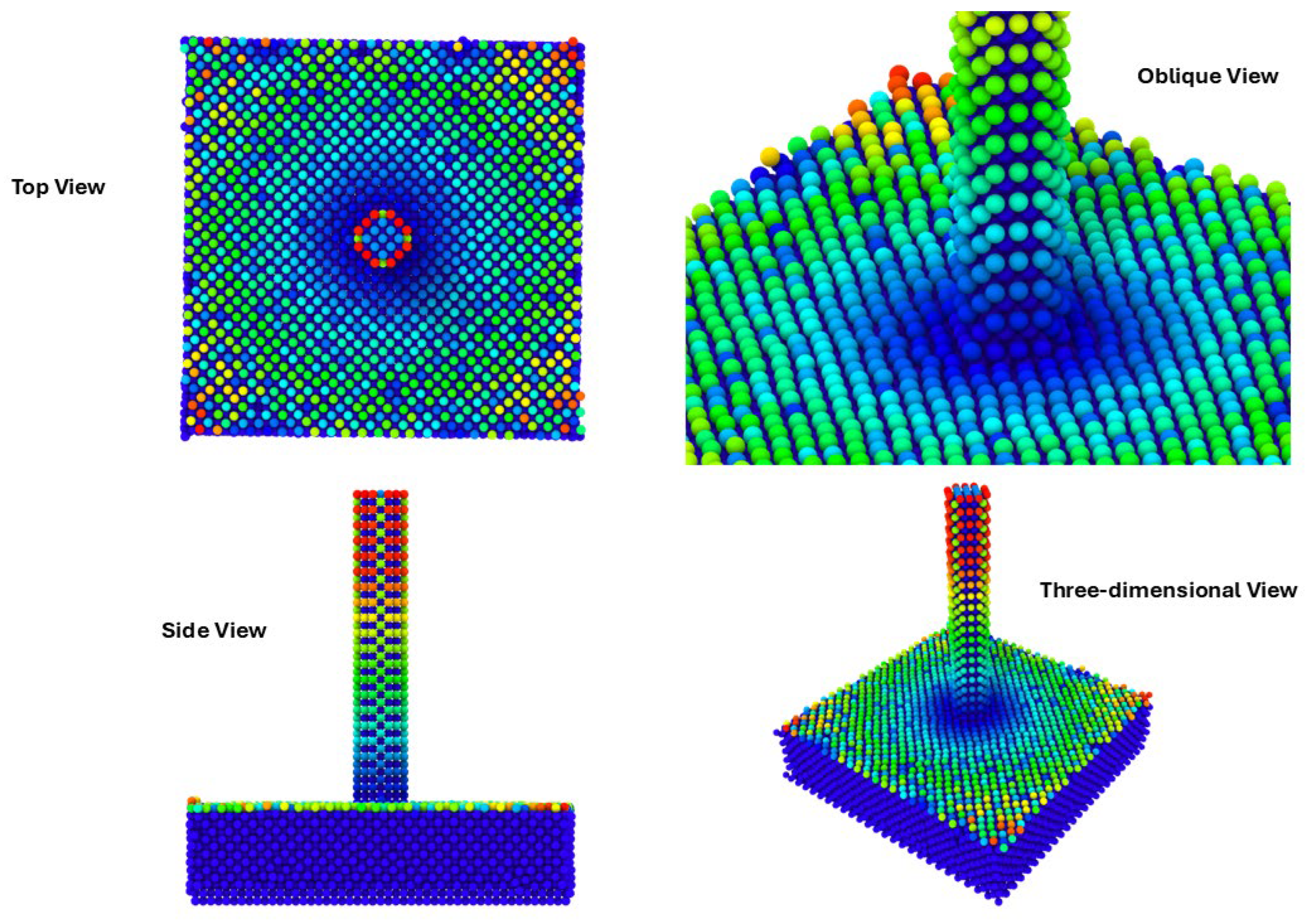
Figure 8.
Spatial distribution of cavity radius during AFSD at an advanced stage of tool engagement. Atoms are colored according to their local cavity radius, shown in (a) top, (b) oblique, (c) side, and (d) three-dimensional perspective views. Elevated cavity radius values are localized beneath the rotating feedstock and at the tool–substrate interface, indicating regions of local dilatation and free-volume accumulation.
Disclaimer/Publisher’s Note: The statements, opinions and data contained in all publications are solely those of the individual author(s) and contributor(s) and not of MDPI and/or the editor(s). MDPI and/or the editor(s) disclaim responsibility for any injury to people or property resulting from any ideas, methods, instructions or products referred to in the content. |
© 2025 by the authors. Licensee MDPI, Basel, Switzerland. This article is an open access article distributed under the terms and conditions of the Creative Commons Attribution (CC BY) license (http://creativecommons.org/licenses/by/4.0/).
Copyright: This open access article is published under a Creative Commons CC BY 4.0 license, which permit the free download, distribution, and reuse, provided that the author and preprint are cited in any reuse.


