1. Introduction
Six-axis industrial robotic arms are widely deployed in intelligent manufacturing scenarios such as assembly, welding, and material handling, demanding comprehensive requirements for high-speed, high-response, and high-stability motion planning and control accuracy. However, during actual operation, traditional trajectory control methods based on static models struggle to ensure end-effector execution precision due to multi-source errors including flexible structure deformation, load disturbance, joint backlash, and thermal expansion, often resulting in path deviation and response lag. Existing research primarily focuses on compensating for single error sources or offline optimization, failing to meet real-time control demands under dynamic conditions. To address this, this paper proposes a real-time trajectory correction method based on multi-source error estimation. By integrating lightweight computation strategies with a high-frequency communication platform, it constructs a high-precision control system suitable for industrial environments. Experimental validation demonstrates its enhanced path stability and task completion capabilities.
1.1. Multi-Source Error Modeling And Control Problem Analysis
1.1.1. Six-Axis Robotic Arm System Modeling and Error Source Classification
System modeling of a six-axis industrial robotic arm requires a unified representation integrating its kinematics, dynamics, and flexible structural characteristics. Under the conventional D-H modeling framework, each joint is described by the position vector
, with the corresponding end-effector position and orientation derived through the forward kinematic function
. However, under multi-source disturbances, significant deviations exist between the ideal model and the actual trajectory [
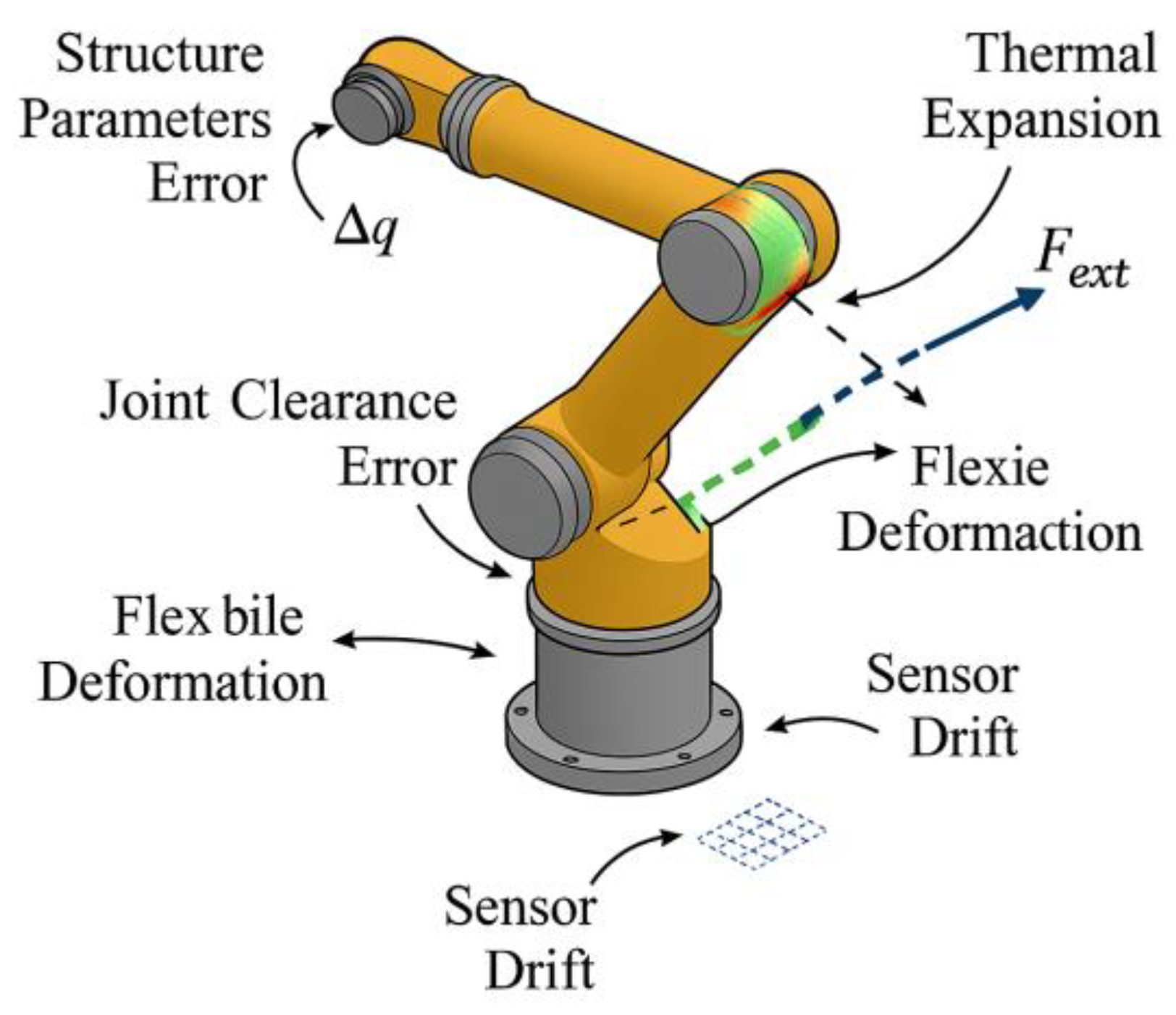
1]. Primary error sources can be categorized into six types: structural parameter errors, joint backlash errors, thermal expansion deformation, load disturbance response errors, flexible arm segment coupling offset, and sensor measurement drift (see
Figure 1). Among these, flexible errors can be modeled as additional disturbance terms:
where `
` denotes the structural stiffness matrix and `
` represents the external end-effector load. Thermal error sources can be calculated using the temperature field `
` and the material thermal expansion coefficient `
` to determine the displacement effect `
`. Additionally, environmental disturbances and installation errors often introduce nonlinear disturbance terms that cannot be neglected.
1.2. Analysis of Error Influence Mechanisms on Trajectory Accuracy
Multi-source errors exhibit significant cumulative effects and nonlinear coupling characteristics on the end-effector trajectory accuracy of six-axis robotic arms. Structural errors introduce initial pose offsets; joint backlash generates deadband hysteresis during reverse motion; flexible deformation causes dynamic path fluctuations; and thermal expansion alters segment lengths, interacting with inertial responses under load. These disturbances collectively compromise trajectory stability. The trajectory deviation can be defined as the transformation residual between the actual end-effector pose and the ideal pose , decomposed into a translation deviation vector and a rotational disturbance [
2]. To further quantify their impact, a perturbation-based mapping relationship can be formulated:
where
represent the Jacobian matrices for joint error, flexible disturbance, and thermal expansion, respectively, and
denote the corresponding error vectors. These parameters are derived through calibrated structural testing and sensor fusion. This formulation shows that multiple error sources influence the end-effector through different mechanical pathways, forming a tightly coupled disturbance field. The nonlinear nature of this coupling often leads to compensation instability under unmodeled or dynamic disturbances, posing a major challenge to traditional static planning methods.
1.3. Control Accuracy Constraints and Real-Time Requirements
High-precision control systems must maintain trajectory stability and end-effector positioning accuracy even when error propagation is amplified. Their performance is bounded by system bandwidth, feedback cycle duration, sampling resolution, and actuator dynamics. The servo loop of a six-axis robotic arm typically operates via the EtherCAT industrial bus, with a control cycle of 0.25 ms and jitter constrained to less than 20 μs. Within this time frame, all control processes must execute, including sensor acquisition, error estimation, trajectory correction, and command issuance [
3]. To prevent performance degradation due to delay accumulation, the system must adhere to a strict command computation window. The control error threshold is defined as:
Where
represents the ideal trajectory point,
denotes the actual execution point, and
indicates the number of trajectory interpolation points per cycle. Additionally, to ensure numerical stability under strong disturbances, the system introduces saturation constraints and damping logic at the control command layer to prevent signal overflow and response oscillations. If the cycle deadline is violated, real-time compensation lags, leading to amplified tracking errors, as shown in
Table 1.
2. Design Of Real-Time Motion Planning And Multi-Source Error Compensation Methods
2.1. System Control Architecture and Modular Process Design
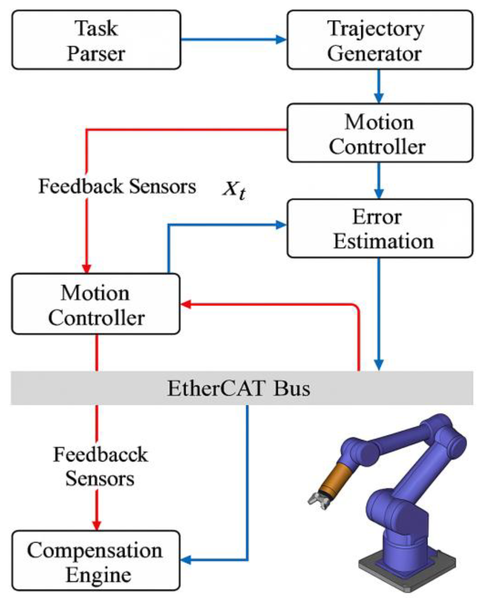
The real-time motion planning system under multi-source error compensation requires a control architecture featuring clear hierarchical levels, closed-loop data pathways, and high-frequency coordination capabilities. The overall system structure comprises five core modules: task analysis and initial trajectory generation unit, error perception and modeling module, online trajectory correction module, control command generator, and low-latency execution platform [
4]. Structurally, the controller employs a cyclic process with the state tensor
as input. At each time step
, the following computational steps must be completed:
Here,
represents the predicted joint pose for the next control cycle,
denotes the state update function based on the joint kinematic-dynamic model, and
signifies the error estimation correction quantity. The central control scheduler integrates error model outputs, path correction interpolation, and command generation logic. It issues closed-loop motion commands via the EtherCAT bus within a 0.25ms cycle (see
Figure 2). All modules in the architecture support parallel decoupling, enabling simultaneous online error sensing from multiple sources and compensatory control.
2.2. Multi-Source Error Estimation Model Construction
The multi-source error estimation model requires collaborative modeling and temporal estimation of errors originating from structural, thermal, force, flexibility, and installation disturbances under dynamic operating conditions. The system achieves error factor identification and quantification by constructing a state-extended observation vector
that fuses sensor data with structural model predictions [
5]. To address the coupling and non-Gaussian distribution characteristics of various error sources, a multi-channel extended Kalman filter (MEKF) is introduced for dynamic estimation of state disturbances. Its state update equation is:
where
is the error estimate at time
,
is the gain matrix, and
is the measurement mapping matrix. To address thermal errors caused by nonlinear flexible disturbances and temperature gradients, the model incorporates an error offset compensation function
, where
is the thermal expansion coefficient and
is the flexible Jacobian matrix. The overall model supports multi-channel parallel processing, enabling the output of multidimensional error estimates within the control cycle to drive downstream trajectory correction modules for online compensation.
2.3. Design of Online Trajectory Correction Algorithm
The online trajectory correction algorithm must possess high-frequency update capability, low computational complexity, and sensitive error response to adapt to path deviations caused by multi-source disturbances under dynamic operating conditions. Based on the desired trajectory
and the current estimated error
, the algorithm constructs an incremental correction strategy. It utilizes multi-scale B-spline interpolation functions to generate continuously differentiable correction path segments
, satisfying continuity and real-time constraints [
6]. The trajectory correction objective function is defined as:
where
is the error estimation input,
is the smoothness adjustment coefficient, the first term controls correction accuracy, and the second term constrains curvature discontinuities. The algorithm achieves coupled optimization of error response and trajectory structure within each interpolation cycle. An incremental update mechanism avoids historical reconstruction operations, enhancing computational efficiency.
2.4. Control Command Generation and Real-Time Issuance Mechanism
The control command generation process must complete trajectory data fusion, joint state calculation, and command formatting within each communication cycle to ensure high synchronization and executability of the output signal. Based on the corrected target trajectory
, the system employs the inverse kinematics mapping function
to compute the target joint pose vector
. This is combined with desired velocity and acceleration to construct the complete servo command vector:
where
represent first- and second-order derivatives, approximated using the three-point difference method or spline interpolation. All control commands are dispatched to the drive node via the EtherCAT bus at a 0.25 ms cycle. To mitigate real-time load fluctuations, the system employs a dual-buffered transmission mechanism, establishing a latch area between the main loop and bus synchronization clock to ensure command queues are scheduled in timestamp order [
7]. The control scheduler dynamically monitors command response status and execution residuals. Upon detecting execution deviation (
), it immediately triggers dynamic compensation commands to correct the error, ensuring the closed-loop response performance of the control chain converges stably within the error threshold.
3. Experimental Validation and Performance Evaluation
3.1. Experimental Platform Setup and Task Scenario Design
The experimental platform is built around an ABB IRB1200 six-axis industrial robotic arm equipped with absolute encoders, providing a 1.44 m working radius and 0.02 mm repeatability. The control system adopts an EtherCAT-based synchronous communication platform, with the master station running a real-time Linux system featuring a high-speed control kernel and a custom trajectory interpolation interface [
8]. A high-precision six-axis force sensor is used for end-effector force monitoring, while thermocouple arrays and inertial units capture dynamic responses and thermal disturbances in flexible arm segments. Data acquisition runs at 2 kHz with a fixed 0.25 ms control cycle. Task scenarios include fastener insertion, frame alignment, and flexible card positioning, covering multi-segment spatial curves and compound rotations. A disturbance simulation module enables dynamic adjustment of load and environmental conditions to evaluate compensation robustness under high-dynamic operation. The platform supports parallel algorithm deployment and repeated experiments, ensuring reliable assessment of control accuracy and compensation performance.
3.2. Comparative Analysis of Path Accuracy and Error Compensation Effectiveness
To evaluate the improvement of trajectory accuracy through multi-source error compensation strategies, statistical analysis was conducted on path tracking data from 600 sets of different load and mounting deviation conditions. The control group employed traditional trajectory planning based on calibrated models, while the experimental group incorporated multi-source error estimation and online correction mechanisms [
9].
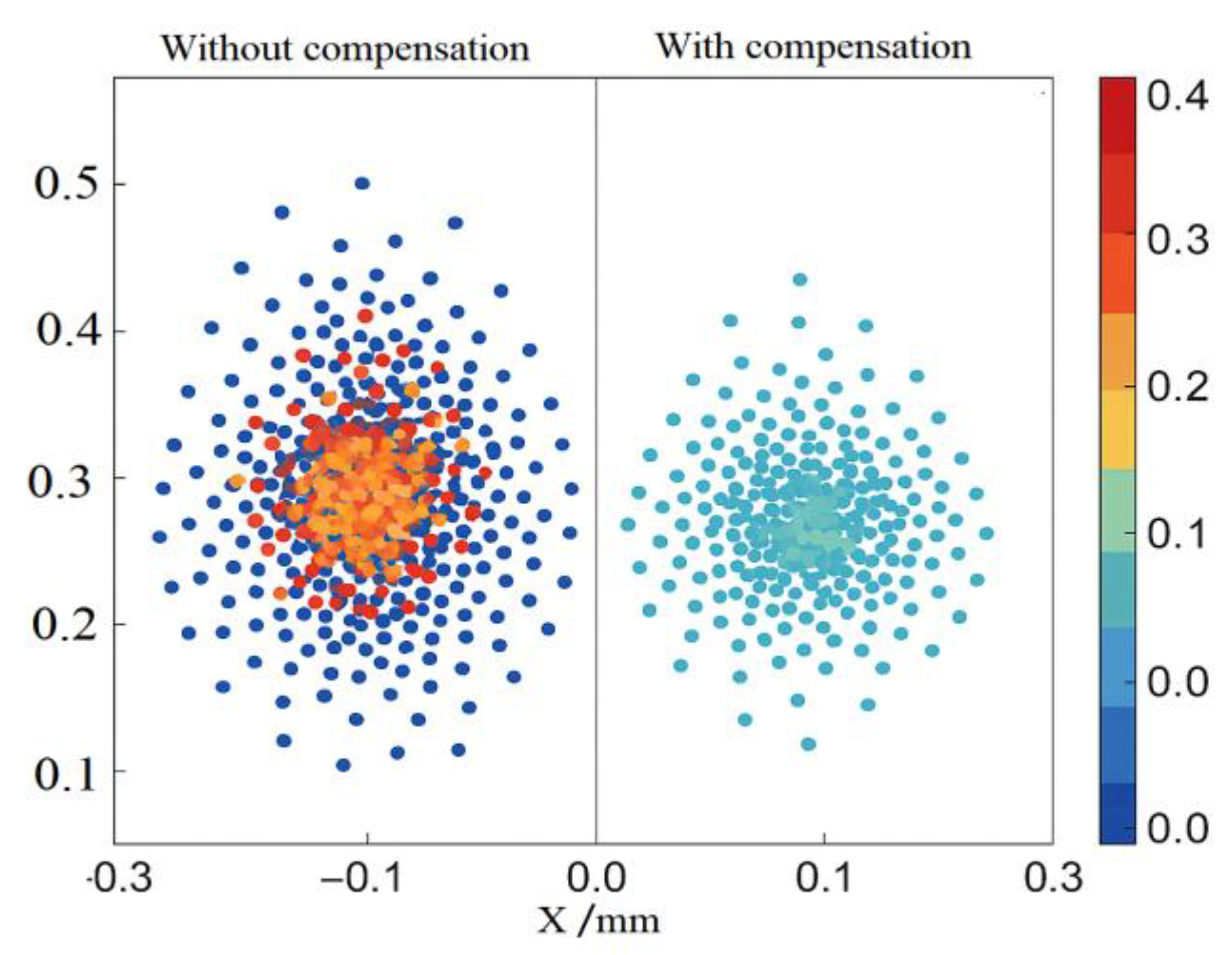
Figure 3 comparison data shows that after error compensation, the trajectory error distribution converged significantly. The central region shifted from a red-orange high-amplitude zone to a blue-green low-amplitude zone, with the overall peak deviation decreasing by approximately 40%. Increased contour density indicates enhanced trajectory stability, and the error tensor distribution became more uniform. Spatial deviations were concentrated within ±0.2 mm, demonstrating the compensation strategy's significant corrective effect under dynamic operating conditions.
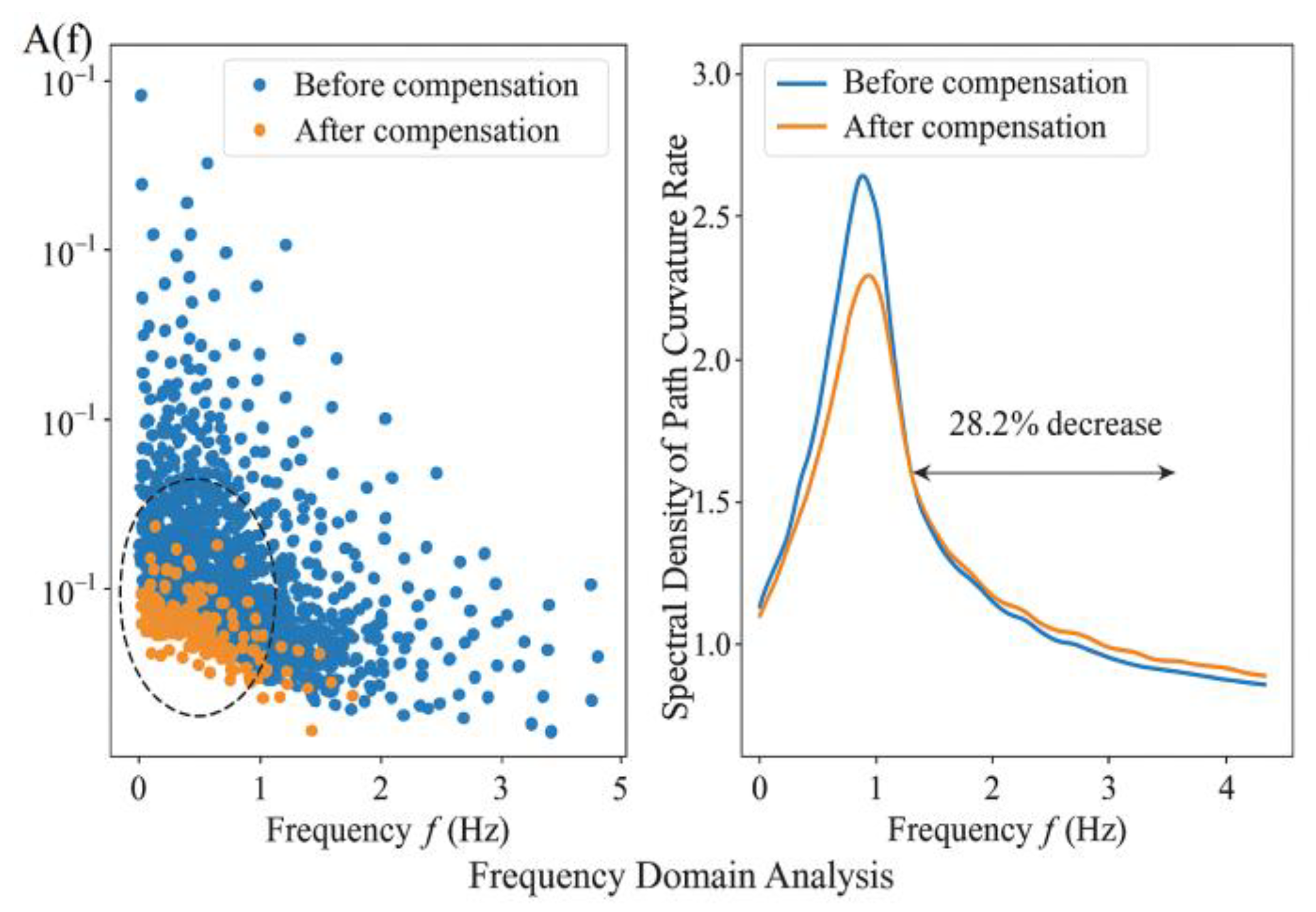
Frequency domain analysis further reveals (see
Figure 4) that the amplitude of high-frequency disturbances in the trajectory significantly decreases after error compensation. The average power spectral density of path curvature variation rate decreases by 28.2%, demonstrating simultaneous enhancements in path smoothness and control stability. Multidimensional data comparisons indicate that this algorithm exhibits excellent trajectory stability and error suppression capabilities under dynamic conditions, possessing strong potential for engineering applications.
3.3. Task Completion Rate and Control Response Performance Evaluation
To validate the impact of the multi-source error compensation mechanism on overall system control performance, experiments were conducted across three typical task scenarios: irregular part insertion, precision hole alignment, and flexible component positioning. These scenarios encompassed varying load amplitudes, trajectory complexities, and force control requirements. Each task group was executed 200 times under random disturbance conditions, with task completion rate, trajectory execution residual, and command response delay recorded [
10]. Results indicate that without compensation, the average overall task completion rate was 89.3%, with primary failures stemming from end-effector deviation exceeding limits and unstable flexible rebound control. After implementing the compensation strategy, the task completion rate increased to 95.7%, with the most significant improvement observed in high-dynamic tasks. Regarding control response, the compensation mechanism reduced the average end-effector tracking error within the cycle from 0.41 mm to 0.24 mm. Simultaneously, command response delay was controlled within 0.18 ms, falling below the upper limit of the EtherCAT control cycle. This validates the compensation logic's engineering applicability in both real-time performance and stability. The dynamic error convergence process exhibited exponential decay, indicating the control system possesses excellent disturbance suppression capability and tracking convergence characteristics.
3.4. Algorithm Complexity and Execution Efficiency Testing
The real-time adaptability of the trajectory correction algorithm directly determines the system's stability and deployability within high-frequency control cycles. To quantify the algorithm's execution load under actual operating conditions, runtime delay, memory consumption, and concurrent task response rates were measured. The algorithm's core module employs a combined optimization of sliding window interpolation, dynamic error projection, and curvature smoothing terms, with a theoretical computational complexity approximating , where represents the number of trajectory nodes within the current window. Experimental data indicates that on a standard industrial controller configuration (Intel Core i7–8700T, 8 GB RAM), the average computational time per cycle is 0.102 ms—significantly lower than the 0.25 ms EtherCAT communication cycle—with maximum latency not exceeding 0.138 ms. Memory usage remains stable below 18.4 MB, showing no abnormal heap growth or garbage collection delays. Under multi-task concurrent simulation, the algorithm maintained a 93.6% in-cycle response rate without control blocking. Test results demonstrate that this modified algorithm exhibits excellent resource control capabilities and real-time performance in high-frequency scheduling scenarios, making it suitable for deploying time-sensitive multi-source compensation control tasks.
4. Conclusions
The proposed multi-source error compensation mechanism for high-precision trajectory control achieves systematic integration of control architecture, error modeling, trajectory correction algorithms, and execution logic. This holistic framework effectively improves both path accuracy and response efficiency across complex operational scenarios. Experimental validations confirm its stability and adaptability under dynamic disturbances and real-time constraints.
However, the current approach has several limitations. It relies on pre-calibrated stiffness, thermal, and flexibility parameters, which may limit its adaptability in variable production contexts. Additionally, the algorithm is primarily designed for single-arm systems; its performance in multi-robot collaborative tasks with coupling dynamics remains unverified. Furthermore, the compensation logic does not yet incorporate autonomous learning or online adaptation capabilities for unknown disturbance distributions.
Future research should address these limitations by exploring adaptive error modeling techniques, self-evolving compensation strategies, and real-time task coordination frameworks for multi-agent systems. Incorporating reinforcement learning–based policies and domain adaptation mechanisms could further enhance the system’s generalization to unstructured or dynamically changing industrial environments.
Conflicts of Interest
The authors declare no conflict of interest.
References
- Zheng, X.; Dwyer, V. M.; Barrett, L. A.; Derakhshani, M.; Hu, S. Rapid vital sign extraction for real-time opto-physiological monitoring at varying physical activity intensity levels. IEEE Journal of Biomedical and Health Informatics 2023, 27, 3107–3118. [Google Scholar] [CrossRef] [PubMed]
- Duan, J; Gong, X; Zhang, Q; et al. A digital twin–driven monitoring framework for dual-robot collaborative manipulation. The International Journal of Advanced Manufacturing Technology 2023, 125, 4579–4599. [Google Scholar] [CrossRef]
- Wang, X; Liu, C; Chen, Y; et al. Hand–eye matrix estimation via motion similarity: a novel multi-source fusion method for eye-to-hand calibration in robotics. Measurement Science and Technology 2025, 36, 046213. [Google Scholar] [CrossRef]
- Cai, J; Ding, H; Wang, P; et al. Digital Twin-Based Intelligent Monitoring System for Robotic Wiring Process. Sensors 2025, 25, 5978. [Google Scholar] [CrossRef] [PubMed]
- Zhu, Z; Zhu, W; Huang, J; et al. An intelligent monitoring system for robotic milling process based on transfer learning and digital twin. Journal of Manufacturing Systems 2025, 78, 433–443. [Google Scholar] [CrossRef]
- Liu, J; Huang, X; Deng, Y; et al. Robotic Positioning Accuracy Enhancement via Memory Red Billed Blue Magpie Optimizer and Adaptive Momentum PSO Tuned Graph Neural Network. Machines 2025, 13, 526. [Google Scholar] [CrossRef]
- Xu, J; Tao, M; Gao, M; et al. Assembly precision design for parallel robotic mechanism based on uncertain hybrid tolerance allocation. Robotic Intelligence and Automation 2023, 43, 23–34. [Google Scholar] [CrossRef]
- Guo, F; Bao, Q; Liu, J; et al. Assembly Quality Control Technologies in Forced Clamping and Compensation Processes for Large and Integrated Aeronautical Composite Structures. Machines 2025, 13, 159. [Google Scholar] [CrossRef]
- Wu, H; Yang, J; Huang, S; et al. A Pareto-Optimal-Based Fractional-Order Admittance Control Method for Robot Precision Polishing. Fractal and Fractional 2024, 8, 489. [Google Scholar] [CrossRef]
- Urrea, C; Domínguez, C. Fault Diagnosis in a Four-Arm Delta Robot Based on Wavelet Scattering Networks and Artificial Intelligence Techniques. Technologies 2024, 12, 225. [Google Scholar] [CrossRef]
|
Disclaimer/Publisher’s Note: The statements, opinions and data contained in all publications are solely those of the individual author(s) and contributor(s) and not of MDPI and/or the editor(s). MDPI and/or the editor(s) disclaim responsibility for any injury to people or property resulting from any ideas, methods, instructions or products referred to in the content. |
© 2025 by the authors. Licensee MDPI, Basel, Switzerland. This article is an open access article distributed under the terms and conditions of the Creative Commons Attribution (CC BY) license (http://creativecommons.org/licenses/by/4.0/).