Submitted:
24 December 2025
Posted:
24 December 2025
You are already at the latest version
Abstract
We presented a high-precision endoscopic shape sensing method using only two calibrated outer cores of a multicore fiber Bragg grating (MC-FBG) array. By leveraging the geometric relationship between two non-collinear outer cores and the central core, the approach determines curvature and bending angle without multiple outer-core measurements, reducing computational complexity and error propagation. Experimental results demonstrate that the proposed method achieves maximum relative reconstruction errors of 1.62% and 2.81% for 2D circular and 3D helical shapes, respectively. Furthermore, arbitrary endoscopic configurations such as α-loops and N-loops are accurately reconstructed, validating the robustness of the method under realistic clinical conditions. This work provides a resource-efficient and high-fidelity solution for endoscopic shape sensing, with strong potential for integration into next-generation image-guided and robot-assisted surgical systems.
Keywords:
fiber Bragg gratings
; 3D shape sensing
; wavelength-division multiplexing
; multi-core fiber
1. Introduction
Three-dimensional (3D) shape sensing is reshaping endoscopy for minimally invasive surgery. Conventional systems provide only two-dimensional (2D) views with limited depth cues, complicating navigation through tortuous anatomy [1,2,3]. By reconstructing the 3D configuration of endoscope in real time-position, curvature and tip pose-shape sensing restores spatial awareness, enables precise lesion localization and instrument guidance, and reduces iatrogenic injury. Continuous shape monitoring also flags excessive bending or looping that can increase patient discomfort and procedural risk, while data-driven feedback supports operator training and helps standardize performance [4,5,6]. When integrated with image guidance or robotic platforms, it enables closed-loop control and more reliable, efficient workflows [7,8,9,10]. Together, these capabilities mark a decisive step toward intelligent, data-driven endoscopy.
Established methods (e.g., electromagnetic tracking [11,12,13], image-based techniques [14,15,16]) provide partial solutions but have limitations including interference, tissue deformation, motion blur, and complex calibration; by contrast, fiber-optic shape sensing (FOSS) enables continuous, high-precision, real-time endoscope shape reconstruction, making it a promising alternative [17,18]. The principle of the FOSS is to convert multi-channel strain measurements from fully/quasi distributed sensors into 3D curvature, and then recover the 3D spatial coordinates of the sensing fiber via a shape-reconstruction algorithm. For short-range applications (from tens of centimeters to tens of meters), the distributed strain sensing approaches are optical frequency-domain reflectometry (OFDR) [25,27] and wavelength-division multiplexing (WDM) [4,7,17]. OFDR systems achieve distributed, high-spatial-resolution strain measurements along the fiber—up to tens of micrometers—by beat-frequency detection; however, the need for an expensive tunable laser source (TLS) limits their practical deployment. In contrast, WDM systems estimate strain from shifts in the Bragg wavelength of a fiber Bragg grating (FBG) array. By precisely controlling the FBG spacing during fabrication, spatial resolutions of a few millimeters to a few centimeters can be obtained. As a more mature and cost-effective demodulation scheme, WDM is well suited for use as an auxiliary modality for endoscopic navigation [4]. For fiber-optic shape sensors, configurations based on fiber bundles [21,22] or on bonding multiple fibers to an elastic substrate (e.g., nickel-titanium, NiTi, wire) [23,24] offer high sensitivity; however, they involve complex packaging and exhibit pronounced geometric mismatch, which can compromise reconstruction accuracy. In contrast, MCF has compact core layout and well-defined geometry, enables accurate 3D shape sensing. Current MCF-based shape-sensing fibers typically employ three or more outer cores surrounding a central core [25,26], and estimate curvature magnitude and bending direction using the apparent-curvature method (ACM). Nevertheless, each outer-core channel is subject to strain-measurement error; therefore, using an excessive number of outer cores can degrade sensing accuracy and increase computational complexity, which is undesirable for real-time, high-precision endoscopic shape sensing. Meng et al. [27] proposed a shape-reconstruction strategy based on projecting the curvature vector onto the directions of two outer cores, which substantially reduces the required number of cores and simplifies the system. However, the method does not calibrate the geometric parameters of the outer cores (i.e., core spacing and core angles); consequently, its shape-reconstruction error is comparable to that of multi-outer-core configurations that use the ACM.
To overcome limitations of conventional MCF-based shape sensing, we propose a method that employs only two outer cores arranged non-collinearly with the central core in an MC-FBG array, together with precise geometric calibration of these two cores. Leveraging the underlying geometry, we derive analytical expressions for the curvature magnitude and bending angle specific to this two-outer-core configuration. The calibration compensates for manufacturing tolerances and packaging-induced deviations in core spacings and angles, thereby reducing systematic bias in the strain-to-curvature mapping. Building on these components, our reconstruction pipeline accurately recovers both 2D and 3D standard shapes and provides a uniform basis for comparing alternative outer-core layouts. Overall, the proposed architecture delivers high accuracy with lower hardware complexity and computational burden, making it well suited for real-time, high-precision, and resource-efficient endoscopic shape sensing.
2. Sensing Principle
The main principle of MC-FBG array-based shape sensing is to derive key 3D curve parameters (i.e., curvature and bending angle) from the discrete strain of multiple outer cores, then reconstruct 3D spatial coordinates iteratively via the moving frame method. According to the Euler-Bernoulli beam theory [30], the strain in the outer core i of a MCF (as shown in Figure 1a) can be expressed as:
where is the curvature, is the core spacing of the ith outer core, denotes the bending angle, represents the angular of the ith outer core relative to the local x-axis, and is the small torsion angle introduced during fabrication, which can be compensated through calibration. denotes the strain experienced by the central core, accounting for both temperature and axial strain.
In conventional seven-core fiber, the outer cores are typically arranged in geometries such as regular hexagon, equilateral triangle (the most common), rectangle, or right triangle, as illustrated in Figure 1b. When the geometric parameters are assumed to take their theoretical values, the apparent curvature method [25] can be used to compute the curvature and bending angle from the measured strains of multiple outer cores. However, since only and are unknowns in Equation (1), two independent equations are sufficient to determine them. As reported in [28], the accuracy of shape reconstruction is largely influenced by strain measurement errors; hence, using a greater number of outer cores introduces more sources of error. In addition, the internal geometric parameters of the MCF after packaging can be calibrated using our previously reported method [29] to reduce measurement errors in curvature and bending angle. Therefore, a shape sensing and reconstruction method based on two calibrated outer cores can effectively reduce computational complexity while improving measurement accuracy.
Taking two outer cores i and j arranged non-collinearly with the central core in MCF as an example (as illustrated in Figure 1c), the projection of the curvature on the line connecting each outer core to the central core can be expressed as:
As shown in Figure 1d, a geometric relationship can be established in the right triangle:
Accordingly, based on the cosine law, the curvature magnitude can be derived as:
and the bending angle is given by:
Thus, the projections of the curvature in the local Cartesian coordinate system can be expressed as:
To enhance the effective spatial resolution, and are interpolated using cubic splines to yield and , with representing the arc length of the curve.Subsequently, the Bishop frame [25] is adopted as the moving frame for reconstruction, in which the unit tangent vector T and two mutually orthogonal normal vectors N1 and N2 satisfy the following relationship:
By integrating the iteratively computed unit tangent vectors, the 3D spatial coordinates along the shape sensor can be reconstructed as:
3. Experiments and Results
3.1. Experimental Setup
As shown in Figure 2, the 3D shape-sensing system based on an MC-FBG array comprises an endoscope (CONCEMED Co., Ltd.) integrated with a fiber-optic shape sensor, a fan-in/fan-out (FIFO; OPTOWEAVE Co., Ltd.) device for the MCF, a seven-core MCF (YOFC Co., Ltd.) with a core spacing of 41.5 µm and a regular hexagonal outer-core layout, an eight-channel FBG interrogator (Wuhan Smart Fiber Co., Ltd.; wavelength range 1522–1572 nm; sampling rate 100 Hz; wavelength resolution 1 pm), and a host PC. The 3D shape sensor was fabricated by packaging the MC-FBG array as described in our previous work [29]; characterization results for the MC-FBG array are provided in Section 3.2. The FIFO connects the shape sensor to the interrogator, which demodulates the Bragg wavelengths, whereas the PC executes the 3D shape-reconstruction algorithm.
3.2. Testing and Calibration
Prior to curvature interpolation, the locations of all sensing points and the two outer-core geometric parameters (i.e., core spacing and core angles) are identified through experimental characterization and geometric calibration of the MC-FBG array. The reflection spectrum of core 1 measured by the FBG interrogator is shown in Figure 3a. Each core in the MC-FBG array contains 27 FBGs. The Bragg-wavelength spacing between the first five FBGs is approximately 3 nm (e.g., 3.23 nm between #1 and #2), whereas that of the remaining FBGs is about 1.5 nm (e.g., 1.41 nm between #5 and #6). Concurrently, the axial spatial distribution of core 1 was characterized using OFDR (IF-LAB laboratory), as shown in Figure 3b. Each FBG length was set to 5 mm to mitigate the influence of non-uniform strain during sensing [31]. The array has a total length of 1235.91 mm; the spacing between adjacent FBGs is ~25 mm for the first five sensors (e.g., #3–#4: 24.99 mm) and ~50 mm for the subsequent ones (e.g., #15–#16: 49.61 mm). This combined wavelength and spatial layout prevents spectral overlap between neighboring FBGs in the highly bendable distal segment of the endoscope. A notably larger gap (~100 mm) is observed between #7 and #8 in Figure 3b due to a missing FBG during fabrication; nonetheless, as evidenced by the shape-sensing and reconstruction results in Section 3.3, this irregularity had negligible impact on overall performance.
According to Equation (1), the core spacing and relative core angle of the two outer cores can be calibrated based on the cosine dependence of Bragg wavelength shifts on bending angles. Figure 3c shows the raw data and cosine fits for cores 2 and 4 at the 1st sensing point, yielding , , and .Similarly, for the 27th sensing point, the calibrated parameters are , , and . These results indicate that the MCF outer-core geometric parameters deviate slightly from their nominal specifications; therefore, calibration is necessary to obtain accurate estimates of curvature and bending angle.
3.3. Standard Shape Sensing
To evaluate the accuracy of the proposed two-core-based shape sensing method, both 2D and 3D standard shapes were reconstructed using three different outer-core configurations: the equilateral triangle, the regular hexagon, and the two-core configuration with a 120° core separation. For the 2D case, a circular arc with a radius of 300 mm was adopted. As shown in Figure 4a1–4a2, without geometric calibration the deviations of the estimated curvature and bending angle from the theoretical values (3.3 × 10⁻³ mm−1 and 0 rad) are comparable across the three configurations considered, confirming that the proposed non-collinear two-outer-core scheme already yields valid estimates. After calibration, the deviations for the two-outer-core case decrease markedly, demonstrating the effectiveness of the calibration procedure. This improvement is also evident in the reconstruction results: as shown in Figure 4a3, the calibrated two-outer-core scheme produces a 2D curve visibly closer to the ground truth than the other three configurations; the quantitative error analysis in Figure 4a4 and Table 1 indicates a maximum relative error (, where denotes the reconstructed position and the ground-truth position; denotes the arc length)of only 1.62%. A similar conclusion holds for a 3D shape—specifically, a left-handed cylindrical helix with a base radius of 100 mm and a pitch of 50 mm—see Figure 4b1–4b4; the maximum relative error is only 2.81%. These results show that shape sensing using two calibrated outer cores in an MC-FBG array effectively improves reconstruction accuracy while maintaining low hardware complexity.
3.4. Arbitrary Shape Sensing
During conventional endoscopic interventions, only the distal tip is visualized, making shaft looping difficult to anticipate; consequently, reconstructing common loop types is necessary. To demonstrate the applicability of the proposed method to realistic endoscopic shape sensing, we reconstructed three commonly occurring loops formed within the body—the α-loop, the reversed α-loop, and the N-loop. The reconstructed shapes closely matched the corresponding endoscopic images (Figure 5a–5c). In addition, arbitrary 3D shapes were reconstructed with similarly high fidelity (Figure 5d). These results confirm that the proposed method can accurately capture endoscope configurations under realistic clinical conditions.
4. Conclusions
In this work, we present a lightweight approach to endoscopic 3-D shape sensing that uses only two non-collinear outer cores, geometrically referenced to the center core of a MC-FBG array. By exploiting inter-core geometric constraints, we derive closed-form expressions for curvature and bending angle and introduce parameter calibration to suppress systematic bias and error propagation, thereby achieving high-accuracy reconstruction with minimal hardware and algorithmic complexity. On canonical shapes, the method attains maximum relative position errors of 1.62% for a 2-D circular arc and 2.81% for a 3-D helix, outperforming uncalibrated multi-outer-core baselines; on clinically relevant configurations (α-, reverse-α-, and N-loops), reconstructions closely match the actual endoscope geometry, demonstrating robustness and practical applicability. These results highlight the method’s effectiveness in providing a low-resource, high-precision solution for practical endoscopic shape sensing applications.
Author Contributions
Conceptualization, Chujie Tu and Bo Xia; methodology, Chujie Tu and Bo Xia; software, Chujie Tu, Xiangpeng Xiao and Jialei Zuo; validation, Chujie Tu, Bo Xia and Weiliang Zhao; formal analysis, Chujie Tu and Bo Xia; investigation, Chujie Tu and Bo Xia; resources, Weiliang Zhao; data curation, Bo Xia and Chujie Tu; writing—original draft preparation, Chujie Tu and Bo Xia; writing—review and editing, Zhijun Yan, Yan He and Weiliang Zhao; visualization, Chujie Tu and Bo Xia; supervision, Zhijun Yan and Yan He; project administration, Zhijun Yan; funding acquisition, Zhijun Yan. All authors have read and agreed to the published version of the manuscript.
Funding
This work was supported by the Concept Validation Project of the Hubei Optics Valley Laboratory under Grant OVL2025YZ006.
Data Availability Statement
The original contributions presented in this study are included in the article. Further inquiries can be directed to the corresponding author.
Conflicts of Interest
The authors declare that the research was conducted in the absence of any commercial or financial relationships that could be construed as a potential conflict of interest.
References
- Z. Fu et al., “The Future of Endoscopic Navigation: A Review of Advanced Endoscopic Vision Technology,” in IEEE Access, vol. 9, pp. 41144-41167, 2021.
- R. Wei et al., “Absolute Monocular Depth Estimation on Robotic Visual and Kinematics Data via Self-Supervised Learning,” in IEEE Transactions on Automation Science and Engineering, vol. 22, pp. 4269-4282, 2025.
- Z. Chen et al., “Data-Driven Methods Applied to Soft Robot Modeling and Control: A Review,” in IEEE Transactions on Automation Science and Engineering, vol. 22, pp. 2241-2256, 2025.
- M. Jang, H. J. Jeon, B. K. Kim, H. Moon, B. Keum and J. Kim, “Real-Time Three-Dimensional Endoscope Shape Monitoring Using Long and Twist-Suppressed Fiber Bragg Grating Sensors,” in IEEE/ASME Transactions on Mechatronics.
- B. J. Spier, M. Benson, P. R. Pfau, G. Nelligan, M. R. Lucey, and E. A. Gaumnitz, “Colonoscopy training in gastroenterology fellowships: Determining competence,” Gastrointestinal Endoscopy, vol. 71, no. 2, pp. 319–324, Feb. 2010.
- Gangwani MK, Haghbin H, Ishtiaq R, et al. Single versus second observer vs artificial intelligence to increase the adenoma detec tion rate of colonoscopy: a network analysis. Dig Dis Sci 2024;69 (04):1380–1388.
- Y. Lu et al., “Autonomous Intelligent Navigation for Flexible Endoscopy Using Monocular Depth Guidance and 3-D Shape Planning,” 2023 IEEE International Conference on Robotics and Automation (ICRA), London, United Kingdom, 2023, pp. 1-7.
- J. W. Martin, B. Scaglioni, J. C. Norton, V. Subramanian, A. Arezzo, K. L. Obstein, and P. Valdastri, “Enabling the future of colonoscopy with intelligent and autonomous magnetic manipulation,” Nature machine intelligence, vol. 2, no. 10, pp. 595–606, 2020.
- H.-E. Huang, S.-Y. Yen, C.-F. Chu, F.-M. Suk, G.-S. Lien, and C.-W. Liu, “Autonomous navigation of a magnetic colonoscope using force sensing and a heuristic search algorithm,” Scientific reports, vol. 11, no. 1, pp. 1–15, 2021.
- Centurelli, L. Arleo, A. Rizzo, S. Tolu, C. Laschi and E. Falotico, “Closed-Loop Dynamic Control of a Soft Manipulator Using Deep Reinforcement Learning,” in IEEE Robotics and Automation Letters, vol. 7, no. 2, pp. 4741-4748, April 2022.
- Dürrbeck C, Schuster S, Sauer BC, et al. Localization of reference points in electromagnetic tracking data and their application for treatment error detection in interstitial breast brachytherapy. Med Phys. 2023; 50: 5772–5783.
- Li, W., Ma, Q., Liu, C. et al. Intelligent metasurface system for automatic tracking of moving targets and wireless communications based on computer vision. Nat Commun 14, 989 (2023).
- Mehta AC, Hood KL, Schwarz Y, Solomon SB. The evolutional history of electromagnetic navigation bronchoscopy: State of the art. Chest. 2018;154(4):935–947.
- N. Keetha et al., “SplaTAM: Splat track & map 3D Gaussians for dense RGB-D SLAM,” in Proc. IEEE/CVF Conf. Comput. Vis. Pattern Recognit., 2024, pp. 21357–21366.
- Yasunaga, H. Saito and S. Mori, “User-in-the-Loop View Sampling with Error Peaking Visualization,” 2025 IEEE International Conference on Image Processing (ICIP), Anchorage, AK, USA, 2025, pp. 1151-1156. [CrossRef]
- X. Ma, X. Wu, L. Zhang and S. Shen, “Enhancing SplaTAM Performance Through Dynamic Learning Rate Decay and Optimized Keyframe Selection,” 2024 IEEE International Conference on Robotics and Biomimetics (ROBIO), Bangkok, Thailand, 2024, pp. 1972-1977.
- Weiliang Zhao, Xiangpeng Xiao, Jialei Zuo, Zhengqi Sun, Hanlin Liu, Yijie Zhang, Minming Zhang, Zhijun Yan, Qizhen Sun, “DFBG-based shape sensor for large-curvature reconstruction,” Proc. SPIE 13639, 29th International Conference on Optical Fiber Sensors, 136398D (22 May 2025).
- Jiang Q, Li J, Masood D (2023), “Fiber-optic-based force and shape sensing in surgical robots: a review”. Sensor Review, Vol. 43 No. 2 pp. 52–71.
- Y. Meng et al., “Multicore Fiber Shape Sensing Based on Optical Frequency Domain Reflectometry Parallel Measurements,” in Journal of Lightwave Technology, vol. 42, no. 10, pp. 3909-3917, 15 May15, 2024. [CrossRef]
- Erin S. Lamb, Zhou Shi, Tristan Kremp, David J. DiGiovanni, and Paul S. Westbrook, “Shape sensing endoscope fiber,” Optica 11, 1462-1467 (2024).
- Y. Lv, H. Li, Z. Yang, Z. Yan, J. Zang, and Q. Sun, “Highly Accurate 3D Shape Sensing Based on Special Fiber OFDR System Assisted with ICP Algorithm,” in 27th International Conference on Optical Fiber Sensors, Technical Digest Series (Optica Publishing Group, 2022), paper Tu1.7.
- Y. Lv, H. Li, Z. Yang, Z. Yan, J. Zang, and Q. Sun, “Highly Accurate 3D Shape Sensing Based on Special Fiber OFDR System Assisted with ICP Algorithm,” in 27th International Conference on Optical Fiber Sensors, Technical Digest Series (Optica Publishing Group, 2022), paper Tu1.7.
- N. Nguyen, M. Parker, O. C. Kara and F. Alambeigi, “Toward Distributed Fiber Optic Shape Sensing of Continuum Manipulators: A Cost-effective and Simple Manufacturing of Sensor Assembly,” 2022 IEEE Sensors, Dallas, TX, USA, 2022, pp. 1-4.
- M. Tavangarifard, W. R. Ovalle and F. Alambeigi, “Single-Fiber Optical Frequency Domain Reflectometry (Ofdr) Shape Sensing of Continuum Manipulators With Planar Bending,” 2025 IEEE International Conference on Robotics and Automation (ICRA), Atlanta, GA, USA, 2025, pp. 838-843.
- J. P., et. al, “Shape sensing using multi-core fiber optic cable and parametric curve solutions,” Opt. Express 20, 2967-2973 (2012).
- Cailing Fu, Shuai Xiao, Yanjie Meng, Rongyi Shan, Wenfa Liang, Huajian Zhong, Changrui Liao, Xiaoyu Yin, and Yiping Wang, “OFDR shape sensor based on a femtosecond-laser-inscribed weak fiber Bragg grating array in a multicore fiber,” Opt. Lett. 49, 1273-1276 (2024).
- Y. Meng et al., “Shape Sensing Using Two Outer Cores of Multicore Fiber and Optical Frequency Domain Reflectometer,” in Journal of Lightwave Technology, vol. 39, no. 20, pp. 6624-6630, Oct.15, 2021.
- Li S, Hua P, Ding Z, Liu K, Yang Y, Zhao J, Pan M, Guo H, Zhang T, Liu L, Jiang J, Liu T. Reconstruction error model of distributed shape sensing based on the reentered frame in OFDR. Opt Express. 2022 Nov 21;30(24):43255-43270.
- W. Zhao et al., “Twist-Compensation and Self-Calibration Method for High Accuracy DFBG-Based Shape Sensing,” 2025 Optical Fiber Communications Conference and Exhibition (OFC), San Francisco, CA, USA, 2025, pp. 1-3.
- Bauchau, O.A., Craig, J.I. (2009). Euler-Bernoulli beam theory. In: Bauchau, O.A., Craig, J.I. (eds) Structural Analysis. Solid Mechanics and Its Applications, vol 163. Springer, Dordrecht.
- Aydin Rajabzadeh, Richard Heusdens, Richard C. Hendriks, and Roger M. Groves, “Calculation of the Mean Strain of Smooth Non-Uniform Strain Fields Using Conventional FBG Sensors,” J. Lightwave Technol. 36, 3716-3725 (2018).
Figure 1.
(a) Schematic of the cross-sectional configuration of a seven-core fiber. (b) Typical configurations of four commonly used outer-core arrangements. (c) Schematic diagram illustrating the principle of the two selected outer cores. (d) Geometric relationship diagram for curvature analysis.
Figure 1.
(a) Schematic of the cross-sectional configuration of a seven-core fiber. (b) Typical configurations of four commonly used outer-core arrangements. (c) Schematic diagram illustrating the principle of the two selected outer cores. (d) Geometric relationship diagram for curvature analysis.
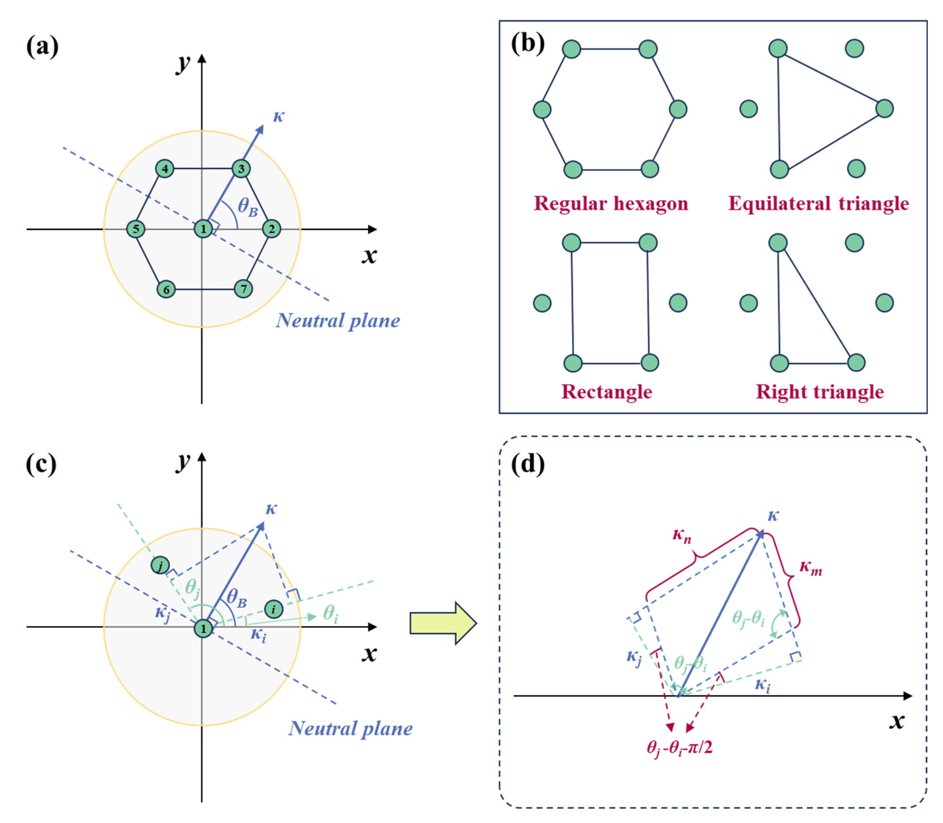
Figure 2.
Schematic diagram of endoscope shape sensing experimental setup.
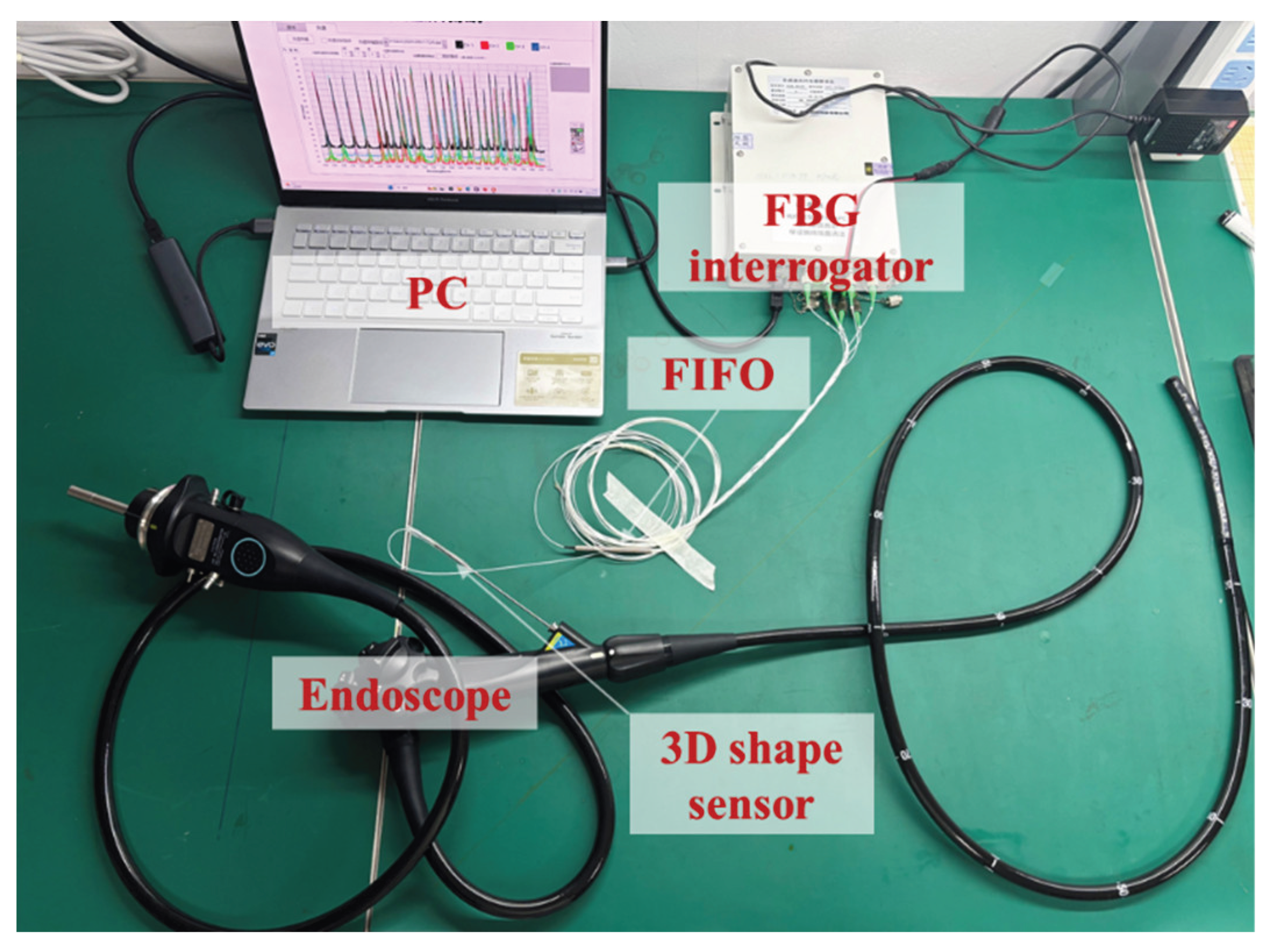
Figure 3.
(a) Reflection spectrum of core 1 in the MC-FBG array. (b) Spatial distribution of core 1 within the MC-FBG array. (c) Geometric parameter measurement results at the 1st sensing point. (d) Geometric parameter measurement results at the 27th sensing point.
Figure 3.
(a) Reflection spectrum of core 1 in the MC-FBG array. (b) Spatial distribution of core 1 within the MC-FBG array. (c) Geometric parameter measurement results at the 1st sensing point. (d) Geometric parameter measurement results at the 27th sensing point.
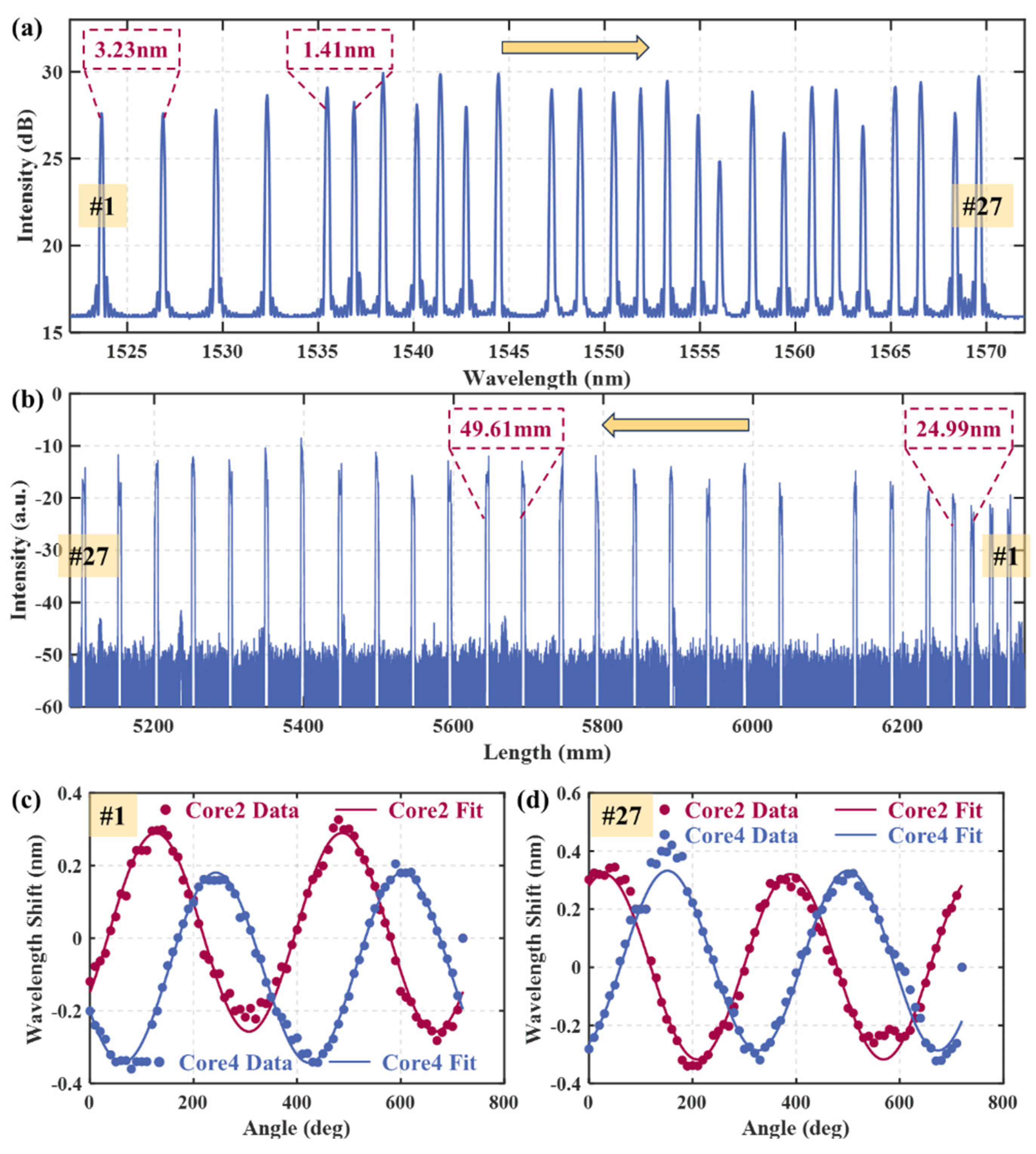
Figure 4.
(a1)- (a4) show the curvature, bending angle, shape reconstruction, and error analysis results obtained using different outer-core configurations for the 2D circular-arc measurement. (b1)- (b4) show the corresponding results for the 3D helical measurement.
Figure 4.
(a1)- (a4) show the curvature, bending angle, shape reconstruction, and error analysis results obtained using different outer-core configurations for the 2D circular-arc measurement. (b1)- (b4) show the corresponding results for the 3D helical measurement.
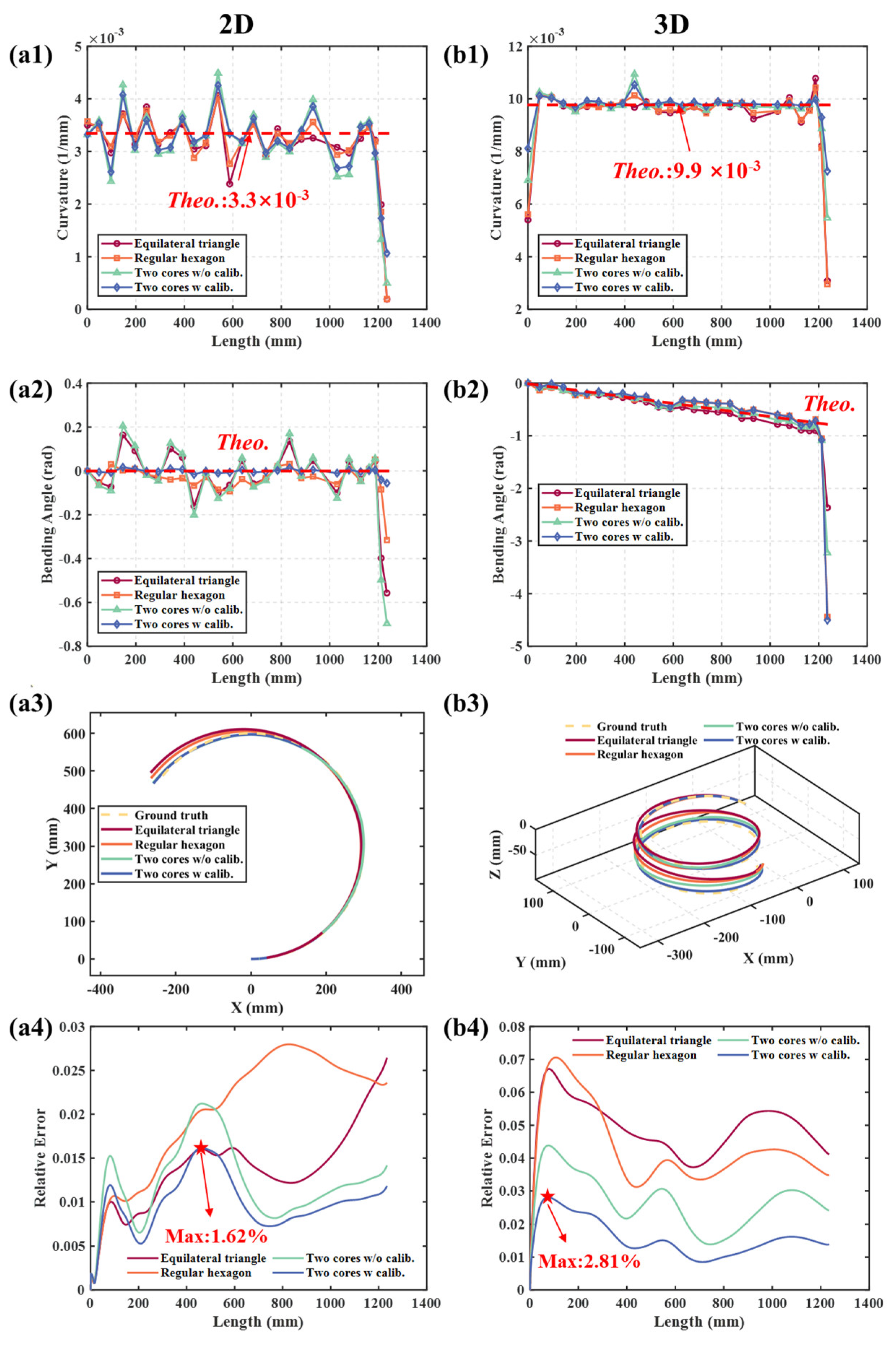
Figure 5.
(a1-d1) Real images of endoscope shapes. (a2-d2) Corresponding reconstructed shapes using two outer cores for the “α” loop, reversed “α” loop, “N” loop, and an arbitrary 3D shape.
Figure 5.
(a1-d1) Real images of endoscope shapes. (a2-d2) Corresponding reconstructed shapes using two outer cores for the “α” loop, reversed “α” loop, “N” loop, and an arbitrary 3D shape.
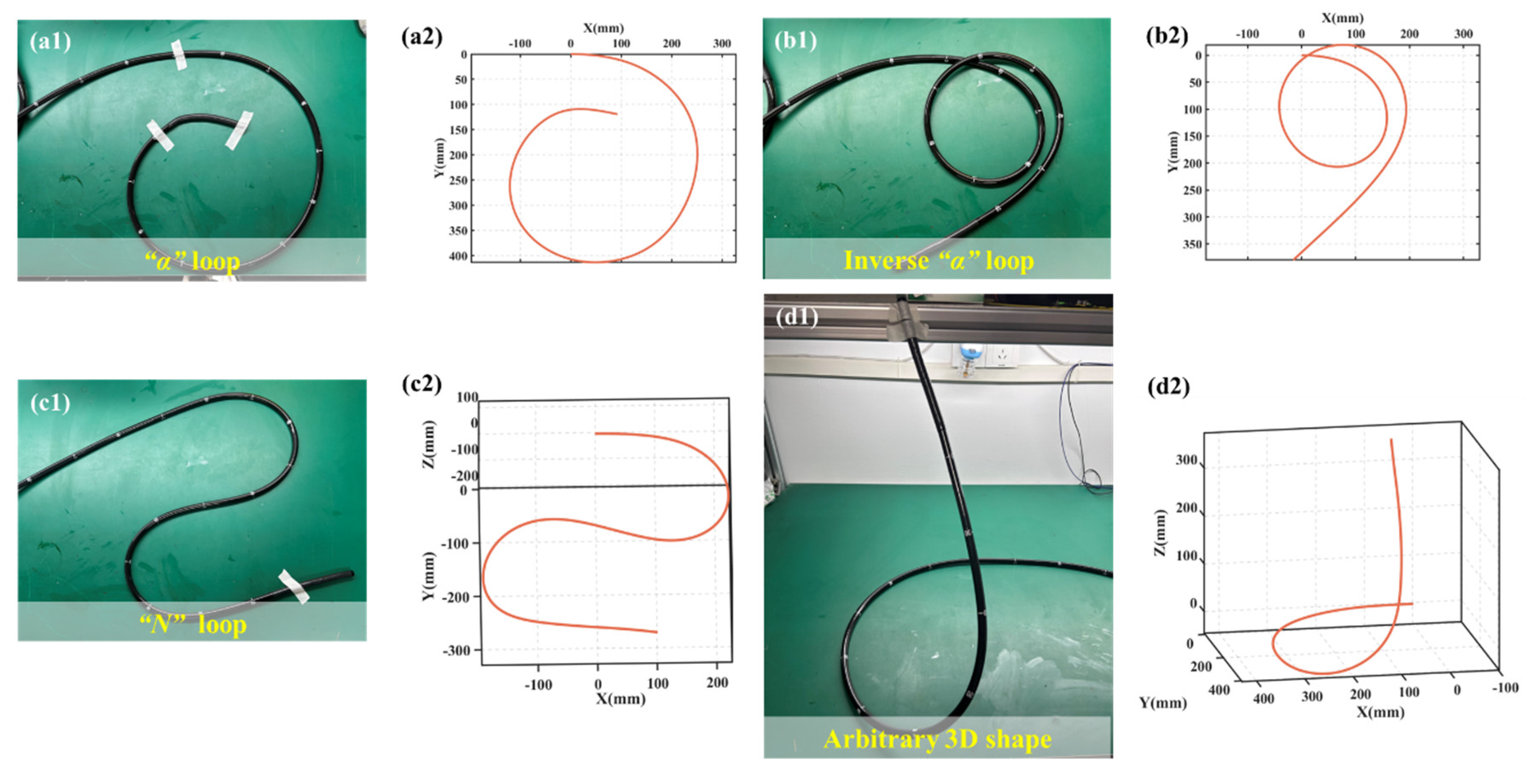

Table 1.
Shape-reconstruction error under the four configurations.
| Dimension | Configuration |
Absolute error (mm) |
Relative error (%) |
| 2D | Equilateral triangle | 32.66 | 2.64 |
| Regular hexagon | 29.15 | 2.80 | |
| Two cores w/o calib. | 17.52 | 2.12 | |
| Two cores w calib. | 14.60 | 1.62 | |
| 3D | Equilateral triangle | 50.78 | 6.71 |
| Regular hexagon | 40.03 | 7.06 | |
| Two cores w/o calib. | 29.78 | 4.38 | |
| Two cores w calib. | 17.16 | 2.81 |
Disclaimer/Publisher’s Note: The statements, opinions and data contained in all publications are solely those of the individual author(s) and contributor(s) and not of MDPI and/or the editor(s). MDPI and/or the editor(s) disclaim responsibility for any injury to people or property resulting from any ideas, methods, instructions or products referred to in the content. |
© 2025 by the authors. Licensee MDPI, Basel, Switzerland. This article is an open access article distributed under the terms and conditions of the Creative Commons Attribution (CC BY) license (http://creativecommons.org/licenses/by/4.0/).
Copyright: This open access article is published under a Creative Commons CC BY 4.0 license, which permit the free download, distribution, and reuse, provided that the author and preprint are cited in any reuse.


