
Submitted:
16 December 2025
Posted:
24 December 2025
You are already at the latest version
Abstract
The determination of the actual series and sequence impedances, including the reduction factor of a certain HV or EHV distribution cable line, as well as the resulting screening factor of its sheaths and surrounding metal installations, including its inductive influence on any of the surrounding metal installations, is not possible by calculations alone. Considering the inductive influence of surrounding metal installations on the values of these quantities is possible only by the method that includes the test measurements during a simulated ground fault in the supplied substation. However, such measurements presuppose putting at least one HV substation and its feeding line out of service. That is why electricity distribution companies rarely allow such measurements, i.e., only immediately before the commissioning of a newly built HV substation or during a periodical overhaul. In this paper, it is demonstrated that these characteristics of cable lines can also be determined based on the results of synchronous measurements performed permanently in the substations at their ends. In this way, the need to perform a simulated ground fault and corresponding test measurements in HV distribution substations is practically disаpear, and the necessary characteristics can be obtained whenever a need for them appears.
Keywords:
power deliver
; reactance
; reactive energy
; transfer capacity
; inductive coupling
; actual reduction factor
; ground fault
; substation
; grounding system
; effective cable sheath
; induced current
; screening effect
; safety conditions
; normal operation
1. Introduction
The problem of determining the favorable inductive influence of surrounding metal installations on the relevant characteristics, during normal operation, as well as in fault conditions, of power lines passing through urban and/or suburban areas, was considered for a long time as an unsolvable one in the professional and scientific public. The main reason for this was the objective limitations, i.e., the impossibility of collecting all relevant data concerning many, known and unknown, underground metal installations situated in the immediate vicinity of these lines. The possibility of determining the actual impedances and other characteristics of power distribution lines appeared for the first time with the appearance and development of contemporary synchrophasor measurement technology. The idea of representing alternating electrical quantities using phasors first appeared back in 1893 in the research publications of the American scientist Ch. P. Steinmetz [1]. Almosa century later, in 1988, Dr A.G. Phadke and J. S. Thorp from Virginia Polytechnic Institute invented the Phasor Measurement Unit (PMU). The prototypes were built later in the same institute [2]. This was soon followed by the progressively increasing use of PMU in power systems, especially for monitoring transmission lines, and it played a significant role in preventing catastrophic failures. Also, a very large number of research papers have been published before achieving the current level of very diverse and valuable applications of this tool. For illustration purposes, some of them have been discussed in review papers [3,4]. So that developed methods based on the synchrophasor measurement can be classified on: Two-Point (Dual-PMU), and Single-Point (Pseudo-Two Point) methods. In addition to these, some methods are not based on synchronous measurements (PMUs or µPMUs). They can be classified as: Multi-Measurement Regression, Probabilistic, and Data-Driven Methods.All these methods have enabled great progress in monitoring and controlling the operation of large distribution systems. A fundamental application is the sufficiently accurate estimation of line impedance parameters (resistance and reactance). The values of these impedances are important for fault location, state estimation, adaptive protection, and Volt-VAR optimization. In order to regulate the application of synchrophasor measurements in modern distribution systems, appropriate technical standards have been developed that require a certain level of accuracy of the quantities that define the phasors of alternating voltages and currents [5,6].
By using the results of synchronous measurements of voltages and currents at the ends of an HV or EHV cable line, the actual impedances of a cable line under normal operation and fault conditions can be determined directly, that is, by using Ohm's low, in each concrete case, e.g. [7]. Certainly, such a way of determining enables taking into consideration the influence of all relevant factors and parameters, including the inductive influence of surrounding metal installations. However, in this way, it is not possible to gain insight into the magnitude of influence and significance of individual relevant factors and parameters. In addition, the cable line characteristics thus obtained in many cases were significantly different from those that could be obtained by the scientific methods known at the time. Because of that, the characteristics of power distribution lines determined in that way are without the necessary scientific foundations. Only based on the results of experimental investigation [8] and the developed methodology versions [8,9,10,11,12], it becomes possible to gain an insight into the factors and parameters that influence the obtained results of synchronous measurements in each concrete case.
One of the effects considered in inductive interaction, the inductive influence of power lines on different nearby metal installations, has been a research subject over six decades. As a result, hundreds of papers, including national and international direrectives [14] have been published. It was necessary to enable determining this influence in different practically possible conditions and circumstances. However, the developed methods were applicable only in a relatively small and limited number of practical cases. That is mainly the case where a scenario of the right-of-way is relatively simple and where all relevant data are available. However, even in such cases, the problem can be so complex that its solution is impossible without the corresponding software and the possibility of modern computers, e.g., [22,23].
The papers [8,9,10,11,12] show that the favorable effects of the mentioned interaction are so pronounced that it can be said that Tesla's alternating currents in urban conditions are significantly more favorable from the standpoint of:
- -
- Magnitude of potentially dangerous touch voltages within and in the vicinity of the supplied HV substations,
- -
- Magnitude of inductive influence of a feeding line on the surrounding metal installations, and
- -
- Power delivery, thanit was known and utilized before.
The previous versions of the mentioned methodology were based on the intro ducedequivalent cable line sheath, which replaces, from the standpoint of its inductive influence, all surrounding metal installations, including all three metal sheaths of the considered cable line [9,10,11]. This equivalent conductor is defined by two relevant parametersthatare necessary to determine in each concrete case. One of them is its longiturinal resistance, while the other is its mean radius. Somewhat later, it is shown that this equivalent conductor/sheath can be substituted by an equivalent sheath, but defined by onlyone relevant parameter. That is its longitudinal resistance [12]. By introducing these so-called effective sheaths into the previously developed methodology, it is achieved that the considered cable line remains unchanged as seen from the outside. Thanks to this, the determinations of all the effects of the inductive interaction between one cable line and the surrounding metal installations are reduced to the simplest cases, which are solvable using standard and well-known calculation procedures [13,14,15,18]. At this, it is taken into consideration that HV and EHV cable lines are, as a rule, with applied cross-bonding [16].
In this paper, it is shown that by using the results of synchronous measurements, as well as the concept of effective sheaths, it is possible to determine the actual characteristics of that line in ground fault conditions, as well as its inductive influence on any of the surrounding metal installations during normal ope ration and during ground fault conditions. Thanks to this, the results of the simulated ground fault and corresponding test measurements can be substituted with results of synchronous measurements easily accessible at any time. This is especially important because the surrounding metal installations cannot be considered as something that will be there the same forever. Over time, old and outdated metal installations are abolished, and new ones with the same or a similar function are introduced. For example, nowadays there is a very pronounced tendency to replace steel water pipes with plastic pipes. Those changes can significantly affect the actual reduction factor of the feeding cable line, that is, the safety conditions within and in the vicinity of the supplied HV substations and the magnitude of inductive influence of an HV or EHV cable line. Therefore, it is a very desirable possibility of timely information about the current value of the reduction factor of each HV or EHV distribution cable line and about its inductive influence.
This methodology enables determining the series and sequential impedances, as well as the actual reduction factor of HV and EHV cable lines and their inductive influence on any of the surrounding metal installations.
It differs from present methods based on synchrophasor measurements because it enables determining the sequential impedances of lines by using measurementresults obtained during normal operation. As these results are, as a rule, more accurate and can be obtained at any time, this fact means a certain advantage for the presented methodology in comparison to the present methods. Most importantly, however, the here developed methodology allows for the determination of the actual reduction factor of the power cable line and its inductive influence on any of the surrounding metal installations. This is not possible by using any of the known methods based on synchronous measurements. In view of this, it can be said that the methodology presented here significantly expands the otherwise wide field of applications of synchrophasor measurements, that is, PMUs and micro -PMUs. Finally, in comparison with its version based on the test measurements during a simulated ground fault, the presented methodology can be applied at any time.
The presented methodology is quite accurate when the input data on voltages and currents at the ends of a cable line under normal operating conditions are also accurate.
2. Problem Description
Electric power distribution networks delivering electrical energy to large urban agglomerations contain, inter alia, a larger number of HV and EHV cable lines passing through urban and/or suburban areas. These areas are, as is well known, also possess-ed of various other metal installations typical of urban environments. Distribution cable lines, together with them, share the same space strictly determined by the width of streets and sidewalks along which they are laid. Because of such a strictly defined and narrow space, a fluctuating magnetic field created by currents in cable line conductors induced a certain electro-motive force in each of the surrounding metal installations. In this way,each of the surrounding metal installations grounded at its ends, together with the ground as a common return path, spontaneously forms one electrical circuit, while all of them, including those formed by the conductors of the inducing cable line, together form a spaciousand complex electrical circuit with many inductively and conductively coupled elements. Each of the induced currents creates its own fluctu0 ating magnetic field, which acts in such a way that it reduces the currents in all other elements of this large and complex circuit. As a result, the intensity of the spacious electromagnetic field that is formed around and along each power distribution cable line is also reduced. As a final effect, the need to produce reactive energy and its transmission through the transmission network and the HV and EHV cable lines themselves, as well as the losses of electrical energy caused by its transmission, are reduced. Of course, this effect is very favorable because, to the extent that the transmission of reactive energy is reduced, transmission capacities are released that can be used for increased transmission of useful active energy.
During a ground fault in an HV distribution substation, large currents and raised potentials appear at places where they normally do not exist. At the place of a ground fault, the fault current leaves the phase conductor and returns to the power system by using all available paths. Because of that, a ground-fault current in an HV distribution substation divides into many smaller current flows. However, for the practice in contemporary power-distribution companies, only two fractions of the total ground fault current are of great importance. One of them is dissipated into the surrounding earth through the grounding system of the supplied substation, while the other is induced in the metal installations surrounding the feeding line.
The currents induced in the surrounding metal installations reduce the fraction of the ground fault current dissipated through the grounding system of the supplied substation into the surroundding earth that produces all potential and potential differences (touch and step voltages) relevant for safety conditions within and in the vicinity of this substation. Thus, without correctly determining the value of this current, it is not possible to put the grounding problem of any HV substation into realistic frameworks and find adequate solutions in each concrete case.
However, the voltages and currents induced in the surrounding metal installations during a ground fault as well as during normal operation can cause, in the first case, an electric shock to the workers who maintain the metal installations and other people that may gate in touch with them; whereas in the second case they can be a threat to the integrity of cathodic protection equipment, pipeline coating, or pipeline steel, including their temporary or lasting dysfunction. Also, the voltages and currents induced by an HV or EHV cable line can cause interference to neighboring communication and control systems. Therefore, the permissible magnitude of voltages induced in surroundding metal installations is strictly determined by the corresponding technical standards, e.g. [20].
For correct protection from the undesirable consequences, it is necessary to determine as much as possible the exact values of the induced voltages and currents, as well as all factors affecting them. However, when we wanted to do this, it was necessary to know all elements of the complete spontaneously formed electrical circuit and all their relevant parameters. However, usually, only that was known about the surrounding metal installations was the following:
- Their structure and spatial disposition are different from case to case,
- Some of them are in direct and continuous contact with the earth,
- By a mandatory applied TN (terra-neutral) grounding system in the LV networks and consumer installations,
- Some of them are interconnected and grounded at certain places, mainly in each of the buildings arrangedalong the streets,
- Most of them are, through metal sheaths of MV cable lines, conductively connected to the substationgrounding electrodes at the ends of HV and EHV distribution lines,
- Some of their sections are not at the same distance or completely in parallel in relation to the considered cableline and in relation to some other of the surrounding metal installations.
Therefore, the problem under consideration can also be treated as a problem of the deficiency of many relevant but unknown data about surrounding metal installations. To gain a more complete insight into the problem we will, for a moment, assume the surrounding metal installations do not exist and that the single-core cables belonging to the considered cable line are laid in the flat formation that, in the general case, from the standpoint of their positions, is shown in Figure 1.
The used notation has the following meaning:
- d – distance between two adjacent single-core cables, and
- rsh – mean radius of the cable sheaths.
For our idea of the spatial position of the metal sheaths of a cable line to be complete, i is necessary to know that contemporary HV and EHV cable lines have applied the cross-bonding [18]. One such cable line can be presented during a ground fault by the equivalent circuit shown in Figure 2.
The used notation has the following meaning:
- A (B) – supply (supplied) substation,
- If – ground fault current when the fault occurs in the supplied substation,
- I1, I2, and I3, - currents induced in the cable line sheaths along corresponding line sections.
The electrical circuit that is spontaneously formed around and along one HV or EHVdistribution cable line during an actual or simulated ground fault in a supplied sub-stationencompasses a certain number of known and unknown metal installations typical of an urbanenvironment. By certain simplifications and idealizations, this circuit can be, according to[11], presented as shown in Figure 3.
Although complete from the standpoint of the number of surrounding metal install ations, thepresented equivalent circuit is not without any idealizations and approximationsof the actualelectrical circuit. First, it has been disregarded that some of these installationsaregrounded at each of the buildings arranged along the same streets as the consideredHV cableline. However, this fact is not of importance to the considered problem because theinduced currents circulate only in the axial direction through these installations. The situation is similar to the one that we havewhen one determines the reduction factor of an overhead line equipped with one or two ground wires. In that case, one does not take into considerationthe fact that the ground wires are grounded at each line tower,e.g.,, [13].
The used notation has the following meaning:
- Uph– phase voltage,
- Un0, Un1, Un2, …, UnN – voltages induced in an arbitrary (n-th) circuit (installation) by the currents in allother circuits presented in Figure 3,
- If – ground-fault current through one of the phase conductors of the considered cable line,
- Ie – currents dissipated into the earth through the grounding system of supplied substation B,
- I1 – current through the sheath of the single-core cable carrying current It,
- I2, I3 – currents through the sheaths of the other two single-core cables,
- I4, I5, …, In, …, IN – currents induced in the individual metal installations,
- Zph – self-impedance of the phase conductor of the considered cable line,
- Z1, Z2, Z3 – self-impedances of the metal sheaths of the considered cable line,
- Z4, Z5, Z6, …, ZN – self-impedances of the individual metal installations,
- ZA(ZB) – impedance of the grounding system of the supply (supplied) substation, and
- N – an arbitrarily large number representing the total number of surrounding metal installations, including the cable line sheaths.
Then, in practice, usually, each of the surrounding metal installations has some sections that are not in parallel in relation to the considered HV cable line and in relation to some other of the surrounding metal installations. Furthermore, in the presented equivalent circuit, the metal installations that are laid along only one section of the considered cable line have not been shown. However, these facts are not relevant in the procedure of the methodology development, as will be seen in the next section.
Also, the soil around and along an HV cable line is normally heterogeneous, but whenwecalculate the self and mutual impedances presented in Figure 3, we assume that it is homogeneous and that its resistivity is equal to its equivalent resistivity. Besides that, as it is wellknown, none of the existing methods enable us to measure the equivalent soil resistivity inurban conditions. It can only be approximately estimated based on the main geological characteristics of the soil surrounding the considered HV cable line, e.g. [10]. Fortunately, the favorable fact is that, according to (1)and (2), these impedances are only slightly dependent on equivalent soil resistivity. At this, it is important to know that for the necessary calculations, a value of equivalent soil resistivity that is somewhat lower than the one approximately estimated. In this way, we are obtainingfinal results that are slightly less favorable from the standpoint of HV line power transfercapacity [10] and slightly on the side of increased safety when determining the actual reduction factor of a cable line [11] and its inductiveinfluence on the surrounding metal installations [9].
By disregarding the inductive influence of metallic installations surrounding an HV orEHV cable line at determining the ground fault currents in the HV substation(s) leadstoground fault currents whose values are somewhat lower than the actual ones [10]. However, taking into account the influence of surrounding metal installations was not possible by usingthe well-known calculation procedure, e.g., [18]. It can be made only by using the method based on the corresponding test measurements during the simulated ground fault in the supplied substation [10]. However, to apply this method, one or even two HV substations needed to be out of service, which, as is known, is possible only in rare situations foreseen by there gular maintenance of the HV distribution networks.
Also, the reduction factor of HV or EHV cable lines can be determined by Using analytical expressions given in [15]. However, by using these analytical expressions, it is not possible to take into account the inductive influence of the surrounding metal installations. This was not possible even using methods based on the capabilities of modern computers [19].
The value of the reduction factor obtained without taking into account the inductive influence of the surrounding metal installations can be, depending on the degree of urbanization of the surrounding area, several times larger than the actual one [8]. Since all potential and all potential differences, including step and touch voltages on the grounding system of the supplied substations, are proportional to this factor, this fact dramatically changed our earlier perception of the magnitude of the grounding problem with these substations. Therefore, determining the actual reduction factor puts the grounding problems of HV distribution substations into realistic frameworks that enables easy and economical solutions, solutions that are in accordance with the real needs in each specific case.
Determining the actual reduction factor of the feeding cable line is possible by using the methodology based on the test measurements during a simulated ground fault in a newly built HV substation, prepared for putting into operation. However, in the design stage of an HV substation, its feeding cable line is usually not completely constructed, and this fact represents a certain practical difficulty in determining the actual reduction factor at that relevant moment. Possibility of overcoming this problem were considered in [11], and, inter alia, itis suggested that the formation of a database on the values of the reduction factor for all existing cable lines in a certain urban area. The creation of such a database would be significantly facilitated by using the presented methodology version based on synchronous measurements.
In cases where there are no transits HV substations between the HV supply one transit and the supplied substation, the value of the actual reduction factor allows us to correctly periodically test the safety conditions within and in the vicinity of a supplied substation. However, when there is at least one transit substation between the supply HV substation and the supplied one due to a practical problem (interrupting the electricity supply to a large number of consumers), it is not possible to obtain permission to perform the necessary test measurements, so we can not obtain the value of the actual reduction factor in these cases. Therefore, in such cases we are forced to make a preliminary assess ment of safety conditions, which in some criticalcases may be insufficient for a definitive assessment concerning safety conditions in the supplied substation [21].
In addition, forming a file with data on the values of the actual reduction factor Of all existing cable lines belonging to a certain HV or EHV cable network, with the aim of a more accurate assessment of the reduction factor in the design stage of future substations, requiresa relatively long time. With the present procedure for obtaining permission for the necessary test measurements, the complete formation of such a file would take many years and perhaps even several decades in the case of huge cities, so-called megalopolises existing in the contemporary world.
One version of the methodology based on test measurements also enables solving the problem of inductive influence in the most complex cases where an HV and EHV cable line is laid along the same streets as many other metal installations typical of urban surroundings. However, when thenumber of these installations is greater, the inductive influence of a cable line on each of them, seen individually, is smaller. Quantitative analysis based on the experimental investigations [8] shows that in the areas of an average degree of urbanization, the induced currents and voltages in any of the surrounding metal installations during normal operation, as well asduring a ground fault in the supplied substation (critical place [9]), is because of the screening effect of other surrounding metal installations, multiple times smaller than would be. Thus, just by taking into account this effect, it becomespossible to put this problem in a realistic framework and find an adequate solution in eachspecific case. Since the actual induced voltages areless than previously possibleto know,it practically means that in many concretecases, the used protection measures against too high (dangerous and/or harmful) induced voltages or currents are redundant.
The practical problem in the application of this methodology version appeared because, to determine any of the unknown induced currents, it is necessary to determine separately the corresponding equivalent sheath of the considered cable line. That pact call means that it is necessary to perform the test measurements with a simulated ground fault for each of the surrounding metal installations.
All considered problems are even more difficult to solve in practice since the surrounding metal installations do not belong to the electrical distribution company, so these companies cannot count on their favorable effects once and forever. Therefore, it is very important to have the possibility of timely determination of the effects of the relevant hanges concerning the surrounding metal installations. Any more significant reduction in the number of surrounding installations may be a reason for repeating some of these easurements. However, such measurements in an HV or EHV distribution network are practically possible only during periodic testing of safety conditions in the supplied substation or during major renovations in that substation, which most frequently means once every five or more years. That is making the present version of the methodology for determining the currents in surrounding metal installations is almost inapplicable in practical conditions.
3. Theoretical Foundations
3.1. Equivalent Sheath
The possibility of introducing the concept of an effective sheath is considered here through a different approach to the problem considered. This approach is based on the electromagnetic theory foundations. Namely, each of the cable lines passing through an urban and/or suburban area can be considered as a spontaneously formed transformer of huge dimensions. By using this analogy, each HV or EHV cable line during a ground fault in the supplied substation (Figure 3) can be presented with certain idealizations and approximateons in the way shown in Figure 4.
The used notation has the following meaning:
- Fr – resultant magnetic flux through the ”primary winding” and
- G – ground.
For obtaining as small as possible number of unknown quantities, the equivalent conductor, substituting all cable line sheaths and all surrounding metal installations from the standpoint of their inductive influence, is imagined as a cylinder around and along the phase conductor with a ground fault current, on the whole line length, as shown in Figure 5.
The relevant parameters of the equivalent sheath, the longitudinal resistance R'eq, and the mean radius req are determined under the condition that the current If and one of the induced currents, I1 (Figure 3), have to remain unchanged after introducing this substitution. According to Figure 4 and Figure 5, this condition is also satisfied if the resulting mag netic flux through the ”primary winding” (the surface closed by the considered phase conductor and the earth as a common return path), Fr, remains unchanged after introdicing this conductor. Also, based on Figure 4 and Figure 5, it is not difficult to see that the equivale ent conductor can be determined for any, including the irregular geometric shape and spatial position of an individual ”secondary winding” (metal installation), as well as for any of their total number, N. Thus, this data was not necessary in the analytical procedure of methodology development, as well as for its application. All relevant data are cumulatively taken into account through the value of the current If and one of the induced currents accessible for the necessary measurement (I1, I2, and I3 in Figure 1). In other words, when we know these currents, or the resultant flux, Fr, it does not matter what geometric shape the current contours have that form individual metal installations with the ground as a return conductor (conductive media). It also does not matter whether any of the metal installationsis laid along the entire length of the cable line or along only one of its sections.
Based on the determined values of the relevant parameters of the introduced equivalent sheath (R'eq and req), we can determine the actual reduction factor of the considered cable line [8,11]. According to Figure 5, for this to be done, we can use the analytical express ion related to the reduction factor of the line consisting of only one single-core cable. By using this expression (e.g. [11]), we have that the actual reduction factor of the considered cable line is:
where
- ra – actual reduction factor of the considered cable line.
This factor takes into account the inductive influence of surrounding metal installations. Once it has been determined by using the procedure presented in [11], the relevant parameters of the equivalent sheath that replaces the surrounding metallic installations from the standpoint of their inductive influence can also be determined only by calculations.
The favorable effects considered have been enabled by the metal installations that surround HV and EHV cable lines in urban conditions, regardless of our need for more efficient electric power delivery. The only thing that we must do is to determine as accurately as possible their inductive influence, i.e., parameters of the equivalent sheath that substitutes all of them, R'eq and req. When these parameters are known, a variety of the mentioned problems become solvable because in the whole surrounding, only the considered cable line with significantly improved and known relevant characteristics exists. Thanks to this, it becomes possible to fully utilise the fact that Tesla's alternating currents, because of the surrounding, known and unknown, metal installations, are more favorable for delivering electricity in urban than in rural conditions.
3.2. Effective Sheaths
Based on (1), it is important to note that the number of combinations of paramet ersR’eq and req that give the same value of ra is infinitely large. In other words, by an unlimited increase in freely chosen value for parameter req, we can obtain an unlimited number of combinations of parameters req and R'eq satisfying (1), that is, an unlimited number of equivalent but mutually different sheaths. This can be seen only based on Figure 4, assuming that the resulting flux, Fr, remains unchanged for each of the newly deter ined equivalent sheaths. This fact enables us to perform one more simplification of the complete equivalent circuit of an HV or EHV distribution cable line (Figure 3). This simplification enables solving the problem considered here. Namely, by imagining that the radius of one of an unlimited number of equivalent sheaths is equal to the radius of the actual sheath of the considered cable line (req= rsh), we obtain the equivalent cable sheath which is, seen from outside, identical to the considered actual one. Such an equivalent sheath is defined only with its longitudinal resistance, R'ef = R'eq(req = rsh). It can be obtained by using (1) and the previously determined value of the actual cable line reduction factor. To distinguish this equivalent sheath from many other equivalent sheaths obtained for different freely chosen mean radius req, this sheath was named the effective cable sheath [12].
The effective sheath, in comparison with the equivalent sheath (Figure 5), has a smaller mean radius. Also, its longitudinal resistance is represented by a complex number. It can be defined as a cable line sheath that, after being introduced, does not change the appearance and spatial position of the considered actual cable sheath. However, ins tead of the actual, it has an effective (apparent) longitudinal resistance. Through the value of this fictive parameter, the inductive influence of all three sheaths of the considered line and all surrounding metal installations spontaneously act as its neutral conductors(Figure 3) is taken into account.
Once the equivalent sheath of a certain cable line has been determined, we can transform it into three effective sheaths, one for each of the phase conductors [12]. In this way, an arbitrarily large number of unknown but relevant data on the constructive characteristics and spatial position of the surrounding metal installations is reduced to only one unknown quantity, the longitudinal resistance of these sheaths. For solving the problems here considered, it is of decisive significance that the external appearance of the actual cable line in this way remains the same.
4. Determination of Effective Sheaths
By introducing the concept of effective sheaths of HV and EHV cable lines [12] each cable line, including the surrounding metal installations, can be presented in Figure 6.
The used notation has the following meaning: URA, USA, UTA, URB, USB, and UTB – voltages of the phase conductors R, S, and T on the receiving and sending ends of the presented cable line, IRA, ISA, ITA, IRB, ISB, and ITB – currents in the phase conductors at both ends of the presented cable line.
By introducing the effective sheaths, the appearance of the cable line seen from outs ide remains unchanged, and the determination of the relevant characteristics of one distribution cable line is reduced to the simplest and well-known case. We have such a case under the unreal assumptions that there are no other metal installations in the entire environment and that cross-bonding is not applied to the considered cable line [18].
Since HV and EHV cable lines are with applied cross-bonding, the induced currents in each sheath of the cable line cancel each other out, so that induced currents in the cable line sheaths practically do not exist. The same case is with the capacitive currents in each sheath. As a result, the currents in the actual sheaths of the cable line are negligibly small, so the presence of these sheaths when it comes to their inductive influence can be disregarded. This means that the effective sheaths of the cable line with applied cross-bonding represent, during normal operation, the substitution only for the surrounding metal installations from the standpoint of their inductive influence.
Embedding modern technologies and systems for synchronized measurements in large power distribution systems, it has become possible to obtain data on voltage and current phasors at both ends of an HV or EHV cable line at the same instant, e.g. [7]. Assuming that we obtained these data for a certain cable line, we can determine the selfimpedance of the effective sheaths using the following system of equations:
where
- IRB, ISB, and ITB – currents in the phase conductors in the supplied substation B,
- ΔUR, ΔUS, and ΔUT – voltage drops along individual phase conductors due to currents IRB,
- ISB, and ITB, respectively.
- ΔUCR, ΔUCS, and ΔUCT – voltage drops along individual phase conductors due to the corresponding capacitive currents,
- I1, I2,and I3 – currents in the effective sheaths of the cable line that correspond to the phase conductors R,S, and T, respectively,
- Zph – self-impedance of the phase conductors,
- Zeff1, Zeff2, and Zeff3 – self-impedance of the effective sheaths of the cable line that correspond to the phase conductors R, S, and T, respectively,
- Zrs (Zsr), Zrt (Ztr), and Zst (Zsr) – mutual impedance between the individual phase conductors,
- Z12 (Z21), Z13 (Z31), and Z23 (Z32) – mutual impedance between the individual effective sheaths of theconsidered cable line,
- Zr1 (Z1r), Zr2 (Z2r), and Zr3 (Z3r) – mutual impedance between phase R and the effective sheaths of theindividual single-core cables,
- Zs1 (Z1s), Zs2 (Z2s), and Zs3 (Z3s) – mutual impedance between phase S and the effective sheaths of theindividual single-core cables,
- Zt1 (Z1t), Zt2 (Z2t), and Zt3 (Z3t) – mutual impedance between phase T and the effective sheaths of theindividual single-core cables.
- Voltage drops ΔURAB, ΔUSAB, and ΔUTAB are determined by:
ΔUR=URA–URB;ΔUS=USA–USB; ΔUT=UTA–UTB
Since the capacitive currents at the beginning of the lines are equal to zero and Sincethey increase linearly with the length of the line, voltage drops ΔUCR, ΔUCS, and ΔUCTare determined by:
However, these capacitive currents are relatively small in practical conditions. For example, on one 110 KV cable line, 4.2 km long in the distribution network of Beograd, measurements made on only one phase conductor at both ends showed that this curent is significantly less than one percent of the current through this phase conductor at the beginning of the line. Besides, based on the analysis performed, e.g., in [10], these capacitive currents in the phase conductors of a cable line do not influence the currents induced in the surrounding metal installations. The longitudinal impedance of any of the phase conductors that we will denote in general as Z′ph is, according to [13], determined by:
Whereas the longitudinal mutual impedance between the phase conductor and its metal sheath, denoted in general asZ′m, is determined by:
The longitudinal mutual impedance between the sheaths of two adjacent single-core cables laid in a flat formation and denoted in general as Z′m1 is determined by:
Whereas the longitudinal mutual impedance between sheaths of the cables laid in outside positions (Figure 1) and denoted as Z′m2 is determined by:
where
- R'ph– longitudinal resistance of the phase conductor (Ω/km),
- rph– radius of the phase conductor (m),
- rsh – mean radius of the single-core cable sheaths (Figure 1),
- d – distance between two adjacent single-core cables (Figure 1),
- ω – angular network frequency: 2πf,
- µ0– magnetic permeability of vacuum: 4π∙10–7 Vs/Am, and
- µr – relative magnetic permeability of the phase conductor.
Since surrounding metal installations in urban areas act as additional neutral conductors of power distribution lines (Figure 3), the longitudinal self-impedance of an arbitrary, n-th, surrounding metal installation with a cylindrical form is, according to [13], determinedby:
Whereas in the case of installations with a full metal cross-section, it is:
The longitudinal mutual impedance between two arbitrary, n-thand m-th, surrounding metal installations is:
where
- R′n – longitudinal resistance of an arbitrary, n-th, surrounding metal installation, (Ω/km),
- rn– mean radius of an arbitrary, n-th, surrounding metal installation (m),
- dnm – the distance between two arbitrary, n-th and m-th, surrounding metal installations (m),
- µr – relative magnetic permeability of the metal that is used for the considered (n-th) installation.
The equivalent earth penetration depth is determined by:
where
- ρ – equivalent soil resistivity along and around the considered cable line (Ωm), and
- f – power network frequency.
Based on the results of synchronous measurements, the known quantities in (2) are: URA, USA, UTA, URB, USB, UTB, IRA, ISA, ITA, IRB, ISB, and ITB, whereas based on the introduced effective sheaths, the known quantities are also all presented mutual impedances. Thus, the only unknown quantities are currents in the effective cable sheaths, or I1, I2, and I3, as well as resistances of the effective sheaths, or Reff1, Reff2, and Reff3 that represent a fictive quantity expressed by a complex number [12]. Accordingly, by solving the system of equations (2), all unknown quantities can be determined.
By determining the effective sheaths (Reff1, Reff2, and Reff3), the inductive influence of an arbitrarily large number of surrounding metal installations grounded at both ends is taken into consideration by only one fictitiously changed parameter of a considered HV or EHV cable line. At this, the constructive characteristics and spatial position of these installations do not have to be known to us at all. The same can be said for the metal sheaths of the considered cable line. Also, it does not matter whether cross-bonding is applied or not and whether the cross-bonding is perfectly implemented so that there are no induced currents at all through the sheaths, or some small induced currents circulate through them. All relevant data on the surrounding metal installations are implicitly involved through the measured values of the currents in the phase conductors. In other words, the returned inductive influence from all induced currents is included through the data on the measured values of these currents. This enables us to continue further procedure of determining the characteristics of the considered cable line as if this line exists in the entire environment, that is, as if the surrounding metal installations do not exist.
During normal operation conditions, an unbalanced current pass through the phase conductors and leaves them through the grounded neutral point(s) in the supplied HV substation. It passes through the grounding system of this substation, and its further path toward the sources in the power system continues through the earth and surrounding metal installations. The distribution of this current between the earth and the surrounding metal installations must remain unchanged by the introduction of the effective sheaths. Since the analytical expression for the calculated reduction factor of cable line is known, e.g.,[13], this condition can be defined by:
where
- rmi– reduction of the unbalanced current through the grounding system by the currents through theeffective sheaths, or only through the surrounding metal installations,
- R'eff – longitudinal effective resistance.
Also, when we determine the currents I1, I2, and I3 by solving the system of equations (2), the condition defined by equation (13) can be defined in another way, i.e., by:
By applying this methodology, the sum of the currents through the phase conductors is determined based on the measurement of these currents at the line end, whereas he sum of the currents through the effective sheaths is a result of the calculations performed by (2).
The parameter of the cable lines, denoted as rmi can be defined as the ratio of the current that is dissipated through the grounding system of the supplied substation into the surrounding earth and the unbalanced current that passes through the phase conductors of the feeding line in normal operating conditions. If this parameter is smaller, the intensity of a fluctuating magnetic field around and along the feeding line during normal operation conditions is smaller. As a result, we have a very desirable increase in the transfer capacity of the feeding line, as well as a reduction of the feeding cable line red uction factor and inductive influence on some of the surrounding metal installations duringnormal operation of the cable line. All these effects enable us to find easy and economical solutions to the grounding problem of the supplied HV substations, accurately determine and utilize the actual transfer capacity of the feeding cable lines, and achieve adequate protection of the surrounding metal installations in certain critical cases.
5. Relevant Characteristics of Cable Lines
a. Actual Series Impedance
Since the single-core cables are in a relatively small distance from each other and since cross-bonding is, as a rule, applied, it is quite realistic to assume that the effective values of resistance Reff1, Reff2, and Reff3 are approximately equal. Therefore, when we, according to the previously presented analytical procedure, determine these resistances, we can, with a slight approximation, adopt that only one of them refers to all three effective sheaths and denote it as Reff. To obtain the considered line transfer capacity that is slightly on the side of increased security, the resistance whose effective value is the largest (i.e., the smallest inductive influence from the surrounding metal installations) is selected. Based on that, the longitudinal self-impedance of all three effective sheaths is, according to [12], determined by:
- ReR′eff – real part of the longitudinal resistance of the effective sheath, R′eff,
- Im R′eff – imaginary part of the longitudinal resistance of the effective sheath, R′eff.
When we obtain the value of impedance Z'eff, we can determine the parameters of one equivalent sheath, which substitutes all three effective sheaths, in fact, all surrounding metal installations. These parameters are, according to [12], determined by:
By using this equivalent conductor/sheath, the cross-section of the cable line modified in this way can be presented as shown in Figure 7.
Based on Figure 7, the mutual impedance between the introduced equivalent sheath and any of the cable line conductors is, according to [12], determined by:
Whereas the self-immediateness of this conductor is:
By using (17) and (18), it is possible to determine the mutual impedances between the equivalent sheath and each of the phase conductors, as well as the self impedance of the introduced equivalent conductor. According to this, the self and mutual impedances of all conductors shown in Figure 7, can be considered as known quantities.
Once we have determined all these impedances, the further procedure for determining the actual series impedance of an HV or EHV cable line is reduced to solving a 4 x 4 primitive impedance matrix (Figure 7). After that, we can determine the actual value of power transfer capacity of the considered line, as is shown in [10,17]. This is the value that takes into account the favorable inductive influence of the surrounding metal installlations.
A quantitative analysis of the influence of the surrounding installations on the transfer capacity of 110 kV distribution cable lines is presented in [10].This beneficial effect is significantly greater for lines with applied cross-bonding than for lines without cross-bonding [17]. Nevertheless, cross-connection is mandatory because the elimination of currents through the sheaths reduces cable heating, which increases the so-called cable ampacity, i.e., the current that can be tolerated through the phase conductors [20].
Of course, if cross-bonding was not applied to the cable line in question, the equivalentsheath determined in this way would include the inductive influence of the actual sheaths, as well.
5.2. Actual Sequences Impedances
In this case, the previously presented matrix for determining the series impedance of theconsidered cable line cannot be used for determining its direct, inverse, and zero sequence impedances, including a ground fault current in the supplied substation, as in the case of a cable line with no cross-bonding [17,18]. As in the case of a cable line with no applied cross-bonding, when a ground fault occurs in the supplied substation, in addition to the currents that are induced in the surrounding metal installations, we also have currents induced in the actual sheaths of the considered cable line. Thus, instead of the cross-section presented in Figure 7, we now have the cross-section with the presented actual cable line sheaths as shown in Figure 8.
According to Figure 8, to determine the actual characteristics of a cable line during a ground fault, we need to determine the effective sheaths of the cable line that include the inductive influence of the surrounding metal installations, including also the inductive influence of the cable line's actual sheaths.
To simplify the analytical procedure for determining the ground fault current in the supplied substation, we can replace all three actual sheaths with only one equivalent sheath. According to e.g. [12], the relevant parameters of this conductor are determined by:
Then, if we assume that the ground fault current passes through the phase conductor denoted by R, we have that the self-impedance of this equivalent sheath is, according to [13], determined by:
Whereas the mutual impedance between this equivalent sheath and phase conductor R is:
Thus, we obtain two equivalent sheaths. Both can be replaced by only one equivalent sheath. Its parameters are determined from the condition that the current induced init is equal to the sum of the currents induced in these two equivalent sheaths. The following system of equations defines this condition:
where
- If – ground fault current through the phase conductor R,
- Ish – part of the ground fault current through the metal sheaths of the cable line,
- Imi – part of the ground fault current through the surrounding metal installations,
- Zsheqr– self impedance of the equivalent sheath substituting cable line sheaths,
- Zmieq– self impedance of the equivalent sheath, substituting surrounding metal installations,
- Zsheqr(Zmieqr) – mutual impedance between the phase conductor Rand the equivalent sheathsubstituting cable linesheaths (metalinstallations),
- Zshmi– mutual impedance between two equivalent sheaths,
- Zeq – self impedance of the equivalent sheath, substituting all surrounding metal installations, includingthe cable line sheaths, and
- Zeqr – mutual impedance between the equivalent sheath, substituting all surrounding metal installations, including the cable line sheaths, and the phase conductor R.
In the given system of equations, the unknown quantities are If, Ish, Imi, Zeqr, and Zeq. As this system of equations is valid for any value of current, If we can temporarily assume that it is known to us and that it is, for example, equal to 1 kA. Also, as any equivalent sheath can be substituted with some other equivalent sheath having an arbitrarily chosen radius [10,12], we can adopt that its radius is equal to the radius of the equivalent sheath that replaces the surrounding metal installations from the standpoint of their inductive influence (req = rmieq). By using in sucha way adopted req, the above system of equations becomes solvable because the unknown quantities are only: currents Ish, and Imi, as well as longitudinal resistance, R’eq. Then, solving the modified (20) allows us to deter mine the relevant parameters of the only one equivalent sheath (R’eq, and rmieq) that replaces all actual sheaths and all surrounding metal installations of a considered cable line. In this way, the problem of determining the sequential impedances of a certain HV or EHV cable line is reduced to solving a 4 x 4 matrix (Figure 7). Accurate determination of these impedances allows us to correctly set the protection relays of a certain cable line. The method presented here is somewhat more accurate than other methods based on synchronous measurements because it uses the results obtained under normal operating conditions.
Also, the ground fault current in the supplied HV substation is somewhat elevated due to the influence of surrounding metal installations, which reduce the zero-sequence impedance of the feeding line. However, this elevation has no practical significance from the standpoint of safety conditions because of the inductive influence of the surrounding metal installations on the distribution of this ground fault current is much more favorable.
However, when we considered an HV substation at the design stage, the anticipated value of the ground fault current was necessary primarily for the appropriate selection of conductors that would carry this current. These conductors must be able to withstand the thermal stresses they will be exposed to during a ground fault without sustaining damage. This ground fault current is typically determined based on studies and analyses of the development of the entire energy system over the next twenty years and more.
5.3. Actual Reduction Factor and Resulting Screening Factor
During a ground fault in the supplied substation, a part of the ground fault current is also induced in the actual sheaths of a cable line and participates in the distribution of this current. Because of that, at determining the actual reduction factor of a cable line, the inductive influence of its actual sheaths should also be taken into account. Based on the parameters of only one equivalent sheath determined by using (22), the considered cable line can be represented during a ground fault by the equivalent cable line model with a cross-section shown in Figure 9.
The analytical expression for the reduction factor of a cable line and screening factor of its sheath for the cable line consisted of only one single-core cable, as presented in Figure 9, is known, e.g., [9]. By using this expression, we obtained:
where
- kr – resulting screening factor of cable line sheaths, including all surrounding metal installations,
- R'eq – longitudinal resistance of the equivalent sheath,
- req – mean radius of the equivalent sheath equals the radius of an equivalent sheath, substituting all surrounding metal installations, according to (22).
In the case where the supplied substation is supplied through one or more transit substations, the actual reduction factor must be determined for the entire feeding line. That means for its determination, we must use the voltages and currents measured in terminal substations. Using the present methodology, it becomes possible only by putting at least two HV distribution substations out of service.
Once we have determined the resulting screening factor, the voltage induced during a ground fault in some designed metal installation that has yet to be laid along the considered cable line is, according to [14], determined based on the following expression:
where
- Zph(N+1) – mutual impedance between the phase conductor and a just-laid installation.
The analogous analytical procedure can also be used in the case of HV overhead lines if there are other metal installations, such as other electric power lines, gas pipelines, or railways, laid along them or along some of their sections. Of course, due to the large distances between overhead lines and them, the inductive influence of the surrounding metal installations in the case of these lines is not pronounced to a significant extent.
5.4. Currents Induced in any of the Surrounding Metal Installations
5.4.1. During a Ground Fault
In this case, we will simplify the problem to the extreme if we replace the actual sheaths and surrounding metal installations with just one effective sheath. By introducing the effective sheath, the external appearance and spatial position of the single-core cable with a ground fault current remain unchanged and can be presented as shown in Figure 10.
Based on Figure 10, we can write the following equation:
where
- Z 'eff - longitudinal self-impedance of the introduced effective sheath,
- Z’effph – longitudinal mutual impedance between the phase and the introduced effective sheath.
- Ii – the total induced current, or
The longitudinal impedance Zeff and Zeffph are determined by expressions (6) and (15), respectively.
In (25), the unknown quantities are currents If and Ii, as well as impedance Zeff. However, in solving practical problems, the value of the current If is usually known in advance. It is determined based on the separately performed analysis/study of the future development of the whole power system. It represents a value that can be actual in twenty or more years. Therefore, it should be assumed that the value of the anticipated ground fault current considers all relevant factors and parameters with acertain reserve on the side of enlarged security.
Additionally, immediately before the commissioning of each newly built HV substation, test measurements are performed to verify safety conditions within and in the vicinity of the supplied substation, e.g., [15]. To obtain a correct estimation it is necessary to determine the actual reduction factor of the feeding line [11]. Then, the total current, induced in the surrounding metal installations, including the actual sheaths of the feeding line, can be determined by:
where
- ra – actual reduction factor of the considered cable line.
When we know currents If and Ii, we can determine the ground faultcurrent fraction Ie that is important for safety conditions within and in the vicinity of the supplied substation. Like the current Ii, this ground fault current fraction cannot be determined in urban areas. However, as shown in Figure 3, it can be determined by:
Also, when we have determined currents If and Ii, we can, by using (25), demine the longitudinal impedance of the introduced effective sheath, Z'eff. When we must determine the current induced in some surrounding metal installation, it goes without saying that all constructive data about this installation, including its spatial position, is known. In such cases, the introduced effectivesheath does not include the installation for which we want to determine the inducedcurrent. According to that, the current induced in an arbitrary m-th installation can be determined by using the following system of equations:
where
- Zm – self-impedance of the m-th surrounding metal installation,
- Z0m – mutual impedance between the phase conductor with current If, and the m-th installation,
- Zmeff(m) – mutual impedance between the effective sheath and the m-thinstallation,
- Im – current induced in the m-th installation, and
- Ii(m) – the total induced current reduced for current Im.
By using the concept of the effective sheath, in addition to reducing the total number of unknown quantities, it is achieved that the impedances Zmph and Zmeff(m) are mutually equal and determined by (15). Since the current Ii is already known (27), the only unknown quantities in (29) are currents Ii(m) and Im. Thus, by solving (29), we can determine the current induced in any of the surrounding metal installations.
As can be seen, many relevant data about other surrounding metal installations, including their total number (Figure 3)are not necessary for the determination ofanyof the induced currents. The whole problem is reduced to the simplest case, where one has one inducing single-core cable and only one induced metal installation.
5.4.2. During Normal Operation
In contemporary HV and EVN cable lines, cross-bonding is mandatory[16]. As a result, the currents induced in their sheaths during normal operation cancel each other, the introduced equivalent sheath replaces only the surrounding metalinstallations. To determine its relevant parameters can be used in the calculation procedurepresented in Section5. However, the mean radius of this equivalent sheath islarge, often greater than 10 meters[10]. To avoid a possible error in determining the mutual impedance between it and the installation in which the inductive influence is to be determined, this equivalent cable sheath must be transformed into a corresponding only one effective sheath and determined separately for each of the single-core cables. Further procedure in this case is presented in the previous Section5.4.1. Finally, the total current induced in a certain installation can be determined bysuperposing all three currents induced by the currents in each of the cable line phaseconductors, that is, by the standard calculation procedure, e.g. [9,14].
From a mathematical point of view, it can be said that based on the presented analytical procedure, any of the unknown currents in the system of equations (2) with an arbitrarily large number of unknown quantities can be easily determined. Using this methodology becomes possible to compensate for a deficiency of an arbitrarilylarge number of relevant, but unknown, data points. Of course, it should be mentioned that this method was developed on a specificcase where the coefficients Zmn and Znm (m Є [1, N], n Є [1, N], m ≠ n) are equal. Therefore, it is valid only for such a system of equations.
6. Quantified Effects of Surrounding Metal Installations
a. Actual Reduction Factor of Cable Lines
The presented methodology enables simple and economical solutions for the grounding problem of HV substations located in urban and suburban areas. For that, it is necessary to form a database of the values of the actual reduction factors of the existing HV and EHV cable lines. This task becomes significantly easier and can be performed in a short time by using the here-presented methodology.
The experimental investigation [8] performed in 2006 in the 110 kV distribution network of Beograd shows that the actual reduction factors of the considered cable lines are 2.04, 3.03, and 5.17 times smaller in relation to their values obtained without taking into account the surrounding metal installations. These results put the whole grounding problem of HV distribution substations in a realistic framework, and dramatically changed our earlier perception of the magnitude of this problem. In general, this leads to simple and more economical solutions for the grounding problem of HV substations located in urban or suburban areas. Certainly, greater effects can be expected in critical cases where, because of high soil resistivity and/or a high short-circuit current level, special measures (e.g. bare copper wire laid in the same trench as the feeding cable line or/and in the same trench as the outgoing MV cable lines, counterpoises, etc.) are considered indispensable to meet the strictly prescribed safety conditions within and in the vicinity of the supplied substation, e.g. [15].Certainly, the largest economic effects can be expected there, where, because of difficult conditions for solving the grounding problem of the supplied substation, a strict requirement for the application ofexpensive MV cables acting as long grounding electrodes (cables with an uncoveredmetal sheath) still exist. For example, such a requirement was for a long time in the distribution company of Beograd, because of the high level of ground-fault currents.
Besides, the presented methodology eliminates the need for preliminary testing and assessment of the safety conditions in cases where it is not possible to obtain permission for performing a simulated ground fault and the foreseen measurements. The research results presented in [21] show that forming the current test circuit only on the linesection between a supplied and transit substation can lead to completely incorrect conclusions concerning the safety conditions in the supplied HV substations. Namely, by using the previously practiced testing procedure in these cases, the prescribed safety criteria can be considered satisfied, although that is not the case, i.e., although too high potential differences and human life losses are possible. The actual reduction factor of a feeding line must include the inductive influence of the surrounding metal installations laid along the entire length of this line.
Based on the analyses and results in [8,11], it is realistic to assume that solving the problem of grounding distribution substations will not require burying bare copper conductors in the ground. The steel reinforcement of the foundation of the building in which the substation is situated and the grounding effects of the metal sheaths of the outgoing MV cables will be sufficient in a huge number of cases. These elements of the grounding system of HV substations located in urban areas exist independently of our need to solve this problem; it is only necessary to estimate and use their spontaneous grounding effects [15].
6.2. Reduction of the Inductive Influence on any of the Surrounding Installations
The presented methodology enables solving the most complex cases of inductive influence that can be encountered in practice. These are the cases when an HV or EHV cable line passes through urban and/or suburban areas, where there are many other, known and unknown, metal installations encompassed by their fluctuating magnetic field. The quantitative analysis performed in [9] shows that in the areas of an average degree of urbanization, the value of the induced voltage in any of the surrounding metal installations during normal operating conditions of the considered 110 kV cable lines are reduced by 70 % and 81% as a consequence of the screening effects of all other surrounding metal installations. When a ground fault current passes through these lines, the induced voltages in any of the surrounding metal installations are reduced for the same reason, by 51% and 64%, respectively. Thus, by using this method, we put each concrete problem in the realistic frameworks, and since the induced voltages are significantly less than it was possible to know before, in many critical cases, we can avoid unnecessary protection measures against too high (dangerous and harmful) induced voltages or currents. Certainly, this methodology can also be applied in simpler cases, which are solvable with some of the present methods, that is, with the methods applicable and sufficiently accurate only then, when all relevant data are known. Besides higher accuracy, the advantage of the here presented methodology over these is that its application does not require the collection of large amounts of input data, which is the case with methods based on the possibilities of modern computers, e.g., [22,23].
6.3. Elevated Transfer Capacity of HV and EHV Distribution Cable Lines
The methodology version presented in [12,22] enabled taking into account the favorable effects of the surrounding metal installations on the transfer characteristics of cable lines with applied cross-bonding, the most common case in the contemporary HV and EHV distribution networks. The quantitative analysis presented in these papers shows that the transfer capacity of two 110 kV feeding cable lines with the same constructive characteristics, but laid through different urban areas with an average degree of urbanization is larger by 32.85% and 39.02%, because of the inductive influence of surrounding metal installations. The final effects are similar to the ones that could be obtained by the technical measure known as compensation of reactive energy. Namely, due to the reduction of the series impedances of HV or EHV cable lines, production, as well as the transfer of useless reactive energy through the whole transmission network and these lines are also reduced.
By using the presented methodology, we can prevent HV and EHV networks from being oversized and avoiding or postponing investments in the very expensive new cablelines and substations. Their high cost, as is well-known, is one of the main reasons whyoneadopts the contemporary concept of distribution line development, known asthe ”smart grids”.
6.4. Reducing Energy Losses in Transmission Networks and HV and EVN Cable Lines
This effect occurs due to the reduced need for the production and transmission of reactive energy through the transmission network, as well as HV and EVN distribution cables. Due to the reduced transmission of useless reactive energy, the heating of the cables is reduced, and their transfer capacities are increased from the standpoint of the maximum permissible heating, that is, the so-called ampacity of the cables. The reduction of energy losses in transmission networks and HV and EVN cable lines occurs due to the very existence of surrounding metal installations, so this useful effect is used spontaneously, that is, without our involvement in any sense, but it is certainly, very useful and desirable.
6.5. Reducing Currents Induced in Cable Line Sheaths
In the case of cable lines with applied cross-bonding, this effect occurs only in the case of a ground fault in the supplied substation, whereas in cable lines, where this technique is not applied; it also occurs in normal operation. In that case, this redaction reduces the heating of the cables and thus increases, to a certain extent, their ampacity.
7. Methodology Verification
For the verification of this method, it is necessary to know in advance the inductive influence of the surrounding metal installations, that is, the parameters R'mieq and rmieq. Then, we can determine the value of the longitudinal resistance of the effective sheaths by using (13), and determine voltages and currents at the ends of the adopted line under normal operating conditions by using (2). Of course, to obtain verification, we will treat these voltages and currents as if they were obtained by synchrophasor measurements. Then we will again use (2), but this time to determine the longitudinal resistance of the effective sheaths by treating it as an unknown quantity. If the value determined in this way matches the value initially adopted as input data, one can conclude that the presented method is completely accurate.
The verification is performed by using the relevant data of a hypothetical cable line. However, these data were adopted so that they are within the range that is practically possible. The term hypothetical is used because one assumes that we know the exact value of the equivalent resistance of the soil surrounding the adopted cable line. However, for well-known reasons, it is not possible in urban conditions. Because of that, we are forced to adopt a rough estimate and use it as such in all necessary calculations. Certainly, this practice would lead to discrepancies between the input data and the final results if we were to use the actual line for verification. The problem arises because we could also consider this mismatch as a consequence of the inaccuracy of the tested methodology. Therefore only when we perform the verification by using the unreal assumption that we know the exact value of equivalent specific soil resistivity, can we be sure that the verification is performed properly. After that, we can know that any error that may occur in solving practical problems can be attributed only to certain arbitrariness in the assessment of equivalent soil resistance and/or possible inaccuracies in synchrophasor measurements [5,6]. In accordance with this, let us assume 110 kV cable line five kilometers long, constructed by cable type XHE 94-A, and with the applied cross-bonding. The phase conductors of these cables are made of aluminum, having a cross-section of 1000 mm2, and in the standard design, their sheaths are made of copper strings, having a total cross-section of 95 mm2, and a mean diameter of 91 mm. Also, we will assume that the distance between the single-core cables, d, is one meter and the power-network frequency is 50 Hz, whereas the equivalent soil resistivity of the relevant urban area is equal to 50 Ωm.
Additionally, we will assume that the equivalent sheath, substituting all surrounding metal installations from the standpoint of their inductive influence, has relevant parameters, whose values are the following: R’'mieq = 0.05 Ω/km and rmieq = 8m. These values were obtained for an actual cable line by experimental investigations performed in the distribution 110 kV network of Belgrade [8].
Finally, for obtaining the values of the voltages and currents at the ends of the adopted cable line, we will assume that the line is connected to a sourceof infinite power and that the total load at the end of the line equals 100 MVA, whereas the power factors have the values 0.99, 0.96, and 0.94 for phase conductors R, S, and T, respectively.
For the adopted data, by using the presented analytical expressions and the system of equations (2), we can form the following primitive matrix of impedances of the cable line considered:
where the presented impedances have the following values:
- Zph = (0.3935 + j3.382) Ω,
- Zeff1= Zeff2 = Zeff3 = (1.508 + j3.1005) Ω,
- Zrs = Z sr = Zst = Zsr= Z12 = Z21 = Z23 = Z32 = Zr2 = Z2r =Zs1 = Z1s = Zt2 = Z2t = Zs3 = Z3s = (0.2465 +j3.0385) Ω,
- Zrt = Ztr = Z13 = Z31 = Zr3 = Z3r = Zt1 = Z1t = (0.2465 + j1.821) Ω,
- Zr1 = Z1r = Zs2 = Z2s = Zt3 = Z3t = (0.2465 + j3.0095) Ω.
By using this primitive matrix and analytical procedure presented in [17], the following series impedance of the adopted cable line is obtained:
Using this value of the series impedance for further calculations, we obtain the following values for currents through individual phase conductors:
Ir = (524.87 – j74.78) A; Is = (- 378.00 – j395.00) A, and Ir = (97,45 – j549.80) A,
Whereas the voltage drops along the individual phase conductors are:
ΔUR - ΔUCR = (0.238 + j0.506) kV; ΔUS - ΔUCS = (0.420 + j0.478) kV and ΔUT - ΔUCT = -(0.637 +j0.211) kV
Then, using these results as input data for equations (2), we obtain the value of the longitudinal resistance of the effective sheaths, R’eff = (0.2525 + j0.0182) Ω/km. Finally, byusing (16), we obtain that parameters R'mieq and rmieq have values identical to the ones we adopted as input data necessary for this verification.
As they do not differ from those we previously adopted as necessary input data, it can be said that the presented method was verified as quite accurate.
Additionally, as shown, the quantitative analysis performed by varying the degree of load asymmetry through phase conductors does not affect the results of applying the method. This also, in a certain way, proves the validity of the method because the inductive influence of the surrounding metal installations depends only on their constructive characteristics and spatial position for a certain value of equivalent soil resistivity along and around the considered cable line. Finally, the successful verification of the method further confirms the most important fact on which the entire methodology is based. By introducing effective sheaths instead of real ones and instead of all surrounding metal installations, it is possible if the resulting magnetic flux through the contour formed by the phase conductors and the ground as the return conductor remains unchanged, e.g., [12].
The presented verification is the best possible one for the following reasons. Voltages and currents at the ends of the lines are determined for the same value of the equivalent soil resistance as the equivalent conductor that replaces the surrounding metal installations from the standpoint of their inductive influence. This is not possible in the case of verification on one real cable line. The value of the equivalent soil resistivity along and around one actual cable line is not known exactly. We are forced to estimate it approximately based on the main geological characteristics of the surrounding soil. Also, for such verification, the results of test measurements with simulated ground fault current would be needed, but for such measurements, as already mentioned, the opportunity arises very rarely, that is, once in five or more years for each specific HV distribution substation (according to internal rules of electric power distribution companies). Then, the results of these test measurements cannot be considered exact, so they cannot serve as abasis for verifying the accuracy of the method presented here.
8. General Considerations
The application of the presented methodology enables taking into consideration the electromagnetic interactions between cable lines and surrounding metal installations in determining:
- the actual transfer capacity of any HV or EHV distribution cable line,
- the actual reduction factor of any HV or EHV distribution cable line,
- the somewhat more accurate value of the total ground fault current in the supplied substations,
- the actual inductive influence of power lines on any of the surrounding metal installations,
- correct testing of safety conditions in all HV substations located in urban areas, and
- total current induced in surrounding metal installations during normal operation
Over a hundred years since the massive use of Tesla's alternating currents began, a methodology has been developed that demonstrates these currents are even more advantages for delivering electrical energy because of metal installations, which in urban areas exist in the immediate vicinity of power cable lines. By applying this methodology, the beneficial effects of the electromagnetic interaction between these installations and a certain cable line can be determined in each specific case. The only adverse effect of the surrounding metal installations is a slight increase in the ground fault current in the supplied substation [10]. This should also be taken into account, especially at setting the protection relays. All favorable effects of surrounding metal installations are more pronounced when the cable line passes through areas with a higher degree of urbanization, that is, there, where our needs for such effects are greater. Also, they are more pronounced when the specific soil resistivity of the surrounding soil is higher, that is, there, where our needs for such effects are greater.
The solution to the problems considered was reached by introducing into the well-known calculation procedure, the concept of the effective metal sheath(s) of the considered distribution cable lines. The concept of the effective sheaths enables taking into consideration the inductive influence of all known and unknown surrounding metal installations by using the results of synchronous measurements at the ends of these cable lines. These measurements are enabled by contemporary synchrophasor technology and telecommunication systems embedded into large electric power networks to continuously monitor, control, and protect them, e.g. [7].
The presented methodology is developed by introducing the specific equivalent sheath defined with only one unknown parameter into the analytical procedure developped under the unreal assumption that the surrounding metal installations do not exist [14]. These sheaths were named the effective sheaths, and they are identical, seen from the outside, to the actual sheaths of the considered cable line. However, their longitudinal resistance is such that the inductive influence of all surrounding metal installations, including all three actual sheaths of the considered cable line, is encompassed through it. The value of this parameter is expressed by a complex number, which, of course, does not correspond to the physical nature of this parameter of electrical conductors. The introduction of such a sheath reduces the number of unknown quantities concerning the surrounding metal installations, which enables the solution of the problems considered.
From the standpoint of the considered electromagnetic phenomenon, the effect of the introduced effective sheath is as if the actual cable line sheaths were laid in soil with lower equivalent soil resistance compared to the soil in which the phase conductors of the considered cable line are laid, and as if their longitudinal resistance is lower. In other words, the inductive influence of surrounding metal installations on the actual sheaths of HV and EHV cable lines is equivalent to a certain decrease in their longitudinal resistances as well as the equivalent resistivity of the surrounding soil [12].
In the analytical procedure used to develop the presented methodology, there are no approximations or simplifications that could affect its accuracy. Thus, any inaccuracy that may arise in its application can only be a consequence of the inaccuracy of input data.
Like other methods based on synchronous measurements, the presented method logy can be used to determine theseries and sequential impedances of distribution lines. Compared to these methods, the methodology presented here has a slightly higher accuracy in determining sequential impedances because it is based on measurement results in normal operating conditions. Its main advantage over these methods, however, is that it also enables the determination of the actual reduction factor of cable lines as well as their impact on surrounding metal installations. This is not the case with the aforementioned methods, so it can be said that the application of this methodology expands the field of application of synchronous measurements.
Compared to the methodology based on test measurements during a simulated ground fault, the methodology presented here has the advantage that it can be applied at any time, i.e. when there is a need for its application, and that its application does not require the engagement of people trained in these measurements. Also, by using the presented methodology, it is possible to determine the actual ground fault current and its actual distribution (reduction factor of the feeding cable line) in supplied HV substations and to form for the designers of future HV substations a very useful file with the data about the value of the actual reduction factor of HV and EHV distribution cable lines of a certain urban area in a relatively short time.
With the aim of more efficient delivery of electrical energy, of course, the favorable effects of the surrounding metal installations are welcome and should be used as much as possible. However, the surrounding metal installations do not belong to the electrical distribution companies, so these companies cannot count on their favorable effects permanently. Over time, old and outdated metal installations are abolished, and new ones with the same or a similar function are introduced. For example, nowadays there is a very pronounced tendency to replace steel water pipes with plastic ones. Those changes can significantly affect the actual reduction factor of the feeding cable line, that is, the safety conditions within and in the vicinity of the supplied HV substations, as well as voltages induced in the surrounding metal installations. Therefore, in the event of a reduction in the number of surrounding metal installations, it is necessary for electricity distribution companies to be aware of the effects of these changes on time, which in critical cases may mean repeated necessary measurements. However, this is not possible with the application of the previous version of this methodology because determining these effectsrequires performing appropriate test measurements during a simulated ground fault in the supplied substation. Such measurements in an HV or EHV distribution network are practically possible only on rare occasions during periodic testing of safety conditions in thesupplied substation or during major renovations in this substation, which most frequently means once every five or more years.
Since the value of the equivalent soil resistivity in urban conditions can only be approximately estimated, the problem of certain arbitrariness in its determination in engIneering practice is effectively overcome by adopting these values of the equivalent soil resistivity that givesfinal results on the side of increased safety. That means that for the necessary calculations, the adopted value of the equivalent soil resistivity should be somewhat lower than the roughly estimated one when we determine the transfer capacity andreduction factor of a certain cable line, as well as its inductive influence [9,10,11]. When it comes to the accuracy of the contemporary synchrophasor measurements, they are nowso accurate that they can be used directly for calculations [5,6].
It should also be mentioned that by applying this methodology, due to the differnt spatial positions of individual phase conductors in relation to the surrounding metal installations, slightly different longitudinal resistance values of the effective sheaths can be obtained. When determining someone of the favorable effects of the surrounding metal installations, this means that we should adopt for further calculation the effective sheath in which the inductive influence of surrounding metal installations is the smallest.
The presented methodology can be applied immediately, that is, without any investments in the new embedded systems and new equipment, as well as in specialeducated personnel for the operation and maintenance of these systems and equipment.
Of course, the same effects also exist with distribution overhead and MV cable lines, but in that case, they are less pronounced and are not of such importance for practice in modern electrical transmission and distribution.
The favorable effects considered have been enabled by the metal installations that surround HV and EHV cable lines in urban conditions, regardless of our need for more efficient electric power delivery. The only thing that we must do is to determine as accurately as possible their inductive influence, i.e., parameters of the equivalent sheath that substitutes all of them, R'mieq and rmieq. When these parameters are known, the mentioned variety of problems can be efficiently solved by using here methodology presented. By using it, it becomes possible to assess and make full utilization of the fact that Tesla's alternating currents, because of surrounding metal installations, are more favorable for delivering electricity in urban areas rather than in rural areas.
9. Conclusions
The paper presents a methodology that, based on results of synchronized measurements of voltage and current at the ends of an HV or EHV cable line during normal operation, enables the determination of its series and sequential impedances, including the actual reduction factor of these lines, as well as the inductive influence on any of the surrounding metal installations. All of these are possible at any time and without any test measurements, which were not possible with the earlier version of the presented method logy, based on the test measurements during a simulated ground fault.
Additionally, the presented methodology enables considering the influence of all relevant factors and parameters, including those that are partially or completely unknown to us. Thus, the analytical procedure presented here represents the final stage in the development of the methodology for determining the effects of electromagnetic interaction between power distribution lines and metal installations that surround them in urban conditions.
Funding
This research received no external funding.
Conflicts of Interest
The authors declare no conflicts of interest.
References
- Zhang, L.; Lei, Y. Dissemination of the Phasor Method in Electrical Engineering in China. IEEE Transactions on Education 2014, 57, 20–24. [Google Scholar] [CrossRef]
- Phadke, G. Synchronized phasor measurements-a historical overview. IEEE/PES Transmission and Distribution Conference and Exhibition, Yokohama, Japan; 2002; 1, pp. 476–479. [Google Scholar] [CrossRef]
- Dusabimana, E.; Yoon, S. A Survey on the Micro-Phasor Measurement Unit in Distribution Networks. Electronics 2020, 9, 305. [Google Scholar] [CrossRef]
- Pattanaik, V.; Malika, B. K.; Panda, S.; Rout, P. K.; Sahu, B. K.; Samanta, I. S.; Bajaj, M.; Blazek, V.; Prokop, L. A critical review on phasor Measurement Units installation planning and application insmart grid environment. Research in Engineering 2024, 24, 103559. [Google Scholar]
- IEEE Std. C37.118.1-2011; IEEE Std. for Synchrophasor Measurements for Power Systems. December 2011.
- IEEE C37.118 IEEE Std C37.118.1a -2014; Standard for Synchrophasor Measurements for Power Systemsˮ.
- Pegoraro, P. A.; Brady, K.; Castello, P.; Muscas, C.; von Meier, A. Line Impedance Estimation Based on Synchrophasor Measurements Power Distribution Systems. IEEE Transactions on Instrumentation and Measurements 2024, 68, 100201013. [Google Scholar] [CrossRef]
- Popović, Lj. M. Influence of Metal Installations Surrounding the Feeding Cable Line on the Ground Fault Current Distribution in Supplied Substations. IEEE Transactions on Power Delivery 2008, 23, 2583–2590. [Google Scholar] [CrossRef]
- Popović, Lj. M. Inductive Influence of HV Cable Lines in Urban and Suburban Areas. ElectricalPower System Research 2019, 176. [Google Scholar] [CrossRef]
- Popović, Lj. M. Inductive influence of surrounding metal installations on power transfer capacity of HV cable lines with applied cross-bonding. International Journal of Electrical Power & Energy Systems 2020, 120, 104963. [Google Scholar] [CrossRef]
- Popović, Lj. M. Determining the Actual Reduction Factor of Distribution Cable Lines with Applied Cross-bonding. Facta Universitatis Series: Electronics and Energetics 2023, 36, 449–464. [Google Scholar] [CrossRef]
- Popović, 12. Lj. M. Effective metal shields of high voltage distribution cable lines. International Journal of Applied Power Engineering(IJAPE) 2023, 12, 451~462. [Google Scholar] [CrossRef]
- IEC Int. Std. 60909-3Short-Circuits Currents in Three-Phase A.C. System-Part 3: Currents During Two Separate Simultaneous Line-to-Earth Short Circuit and Partial Short-Circuit Flowing Through Earth, Ed. II ed; 2003.
- CCITT Directives concerning the protection of telecommunication lines against harmful effects from electric and electrified railway lines. ITU: Geneva, 1990; 13.
- IEEE Guide for Safety in AC Station Grounding. IEEE Std. 80 2000.
- IEEE Guide for Bonding Shields and Sheaths of Single-Conductor Power Cables Rated 5 kV through 500 kV. IEEE Standard 575–2014.
- Popović, 17. Lj. Transfer characteristics of electric-power lines passing through urban and suburban areas. International Journal ofElectrical Power & Energy Systems 2014, 56, 151–158. [Google Scholar]
- Kersting, W. H. Distribution System Modeling and Analysis, 1st ed; CRC Press LLC: Washington, D.C., 2002; Volume ch. 4, pp. 77–108. [Google Scholar]
- Benato, R.; Sesa, D. S.; Guglielmi, F. Ground Return Behavior in High Voltage Alternating Current Insulated Cables. Energies 2014, 7, 8116–8131. [Google Scholar] [CrossRef]
- NACE Standard Recommended Practice SPO177-2007; Mitigation of Alternating Current and Lightning Effects on Metallic Structure and Corrosion Control Systems. 2007.
- Popović, 21. Lj. M. Preliminary testing and assessment of safety conditions of HV substations located in urban areas. Electric Power System Research 2021, 195, 107111. [Google Scholar] [CrossRef]
- Christoforidis, G.C.; Labridis, P.D.; Dacopoulos, P.S. Inductive influence on pipeline buried in multilayer soil due to magnetic field from nearby power lines. IEEE Transactions on Electromagnetic Compatibility 2005, 47, 254. [Google Scholar] [CrossRef]
- Bortels, L.; Docaninck, J.; Pineiro, J.I.; Munteanu, C.; Topa, V. A general applicable model for AC predictive and mitigationtechniques for pipeline networks induced by HV power lines. IEEE Transactions on Power Delivery 2005, 21, 210. [Google Scholar] [CrossRef]
Figure 1.
Single-core cables laid in a flat formation [10].
Figure 1.
Single-core cables laid in a flat formation [10].
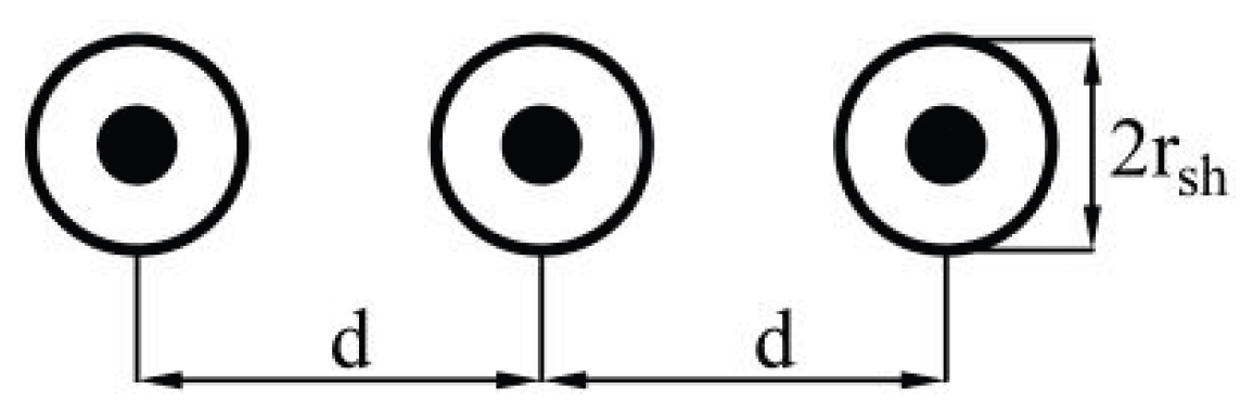
Figure 2.
Equivalent circuit of the cable line with cross-bonding [21].
Figure 2.
Equivalent circuit of the cable line with cross-bonding [21].
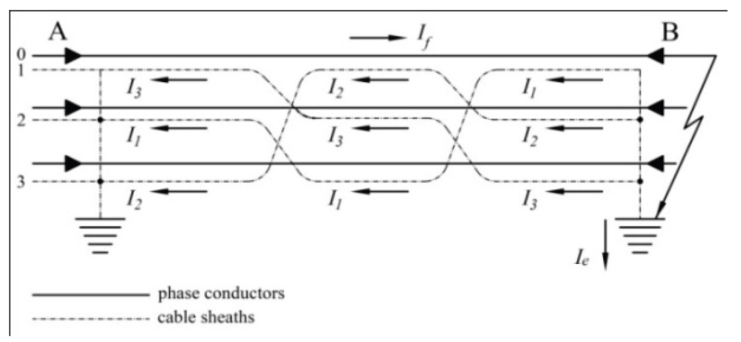
Figure 3.
Complete equivalent circuit of an HV or EHV cable line [10].
Figure 3.
Complete equivalent circuit of an HV or EHV cable line [10].
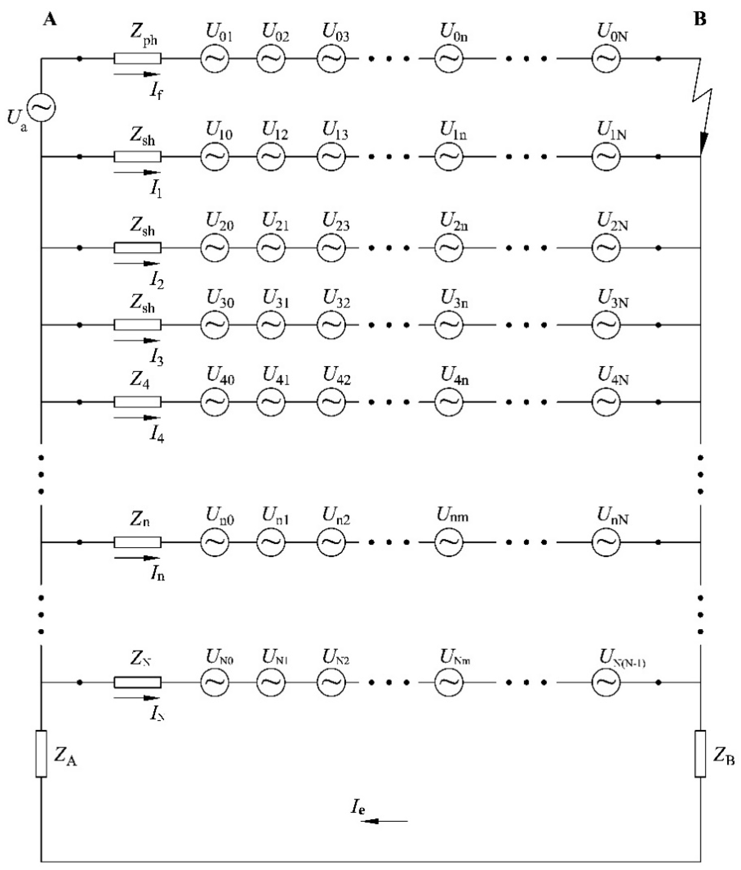
Figure 4.
Cable line during a ground fault presented as a specific transformer [10].
Figure 4.
Cable line during a ground fault presented as a specific transformer [10].
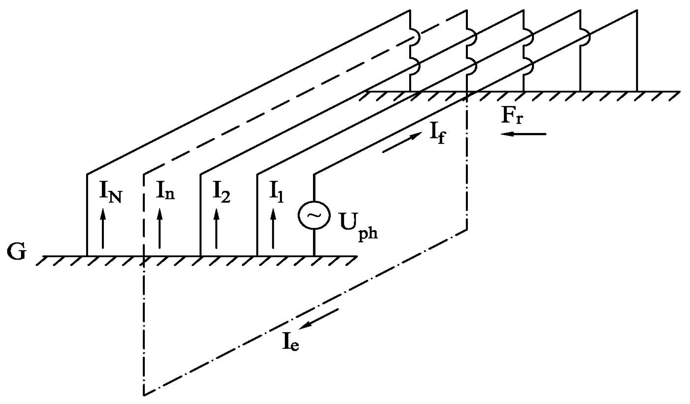
Figure 5.
Equivalent sheath and a phase conductor with current If.
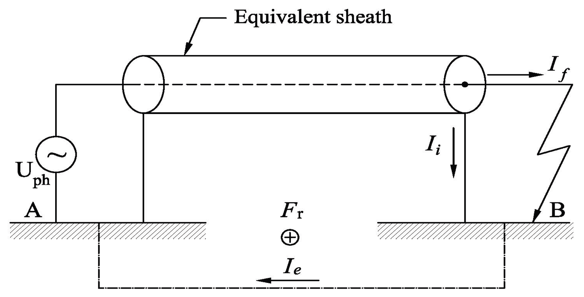
Figure 6.
Measured quantities at the cable line terminals.
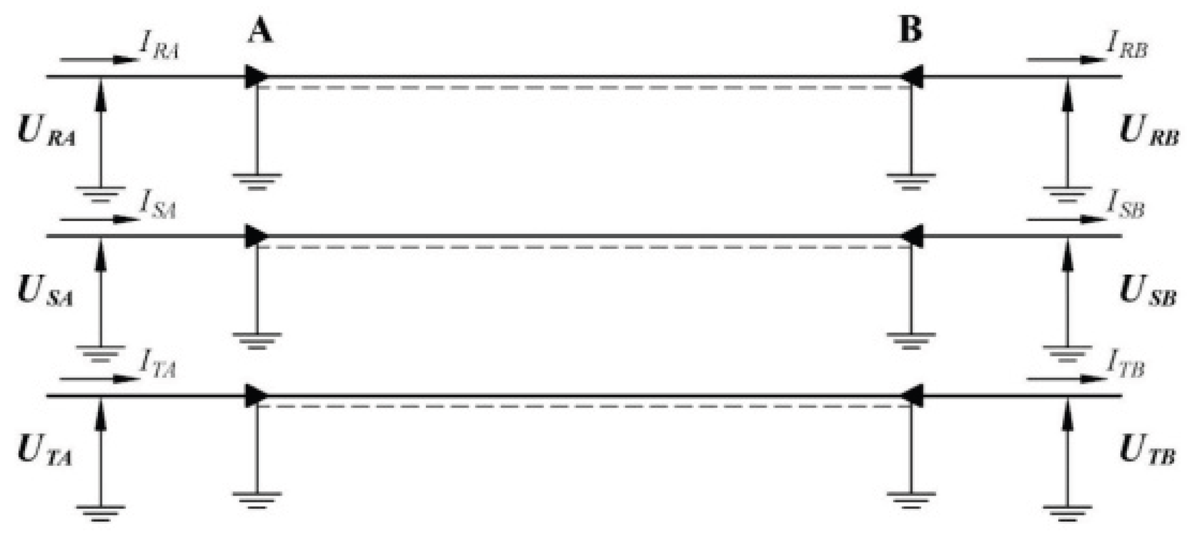
Figure 7.
Cross-sectionof a cable line with one equivalent sheath (conductor).
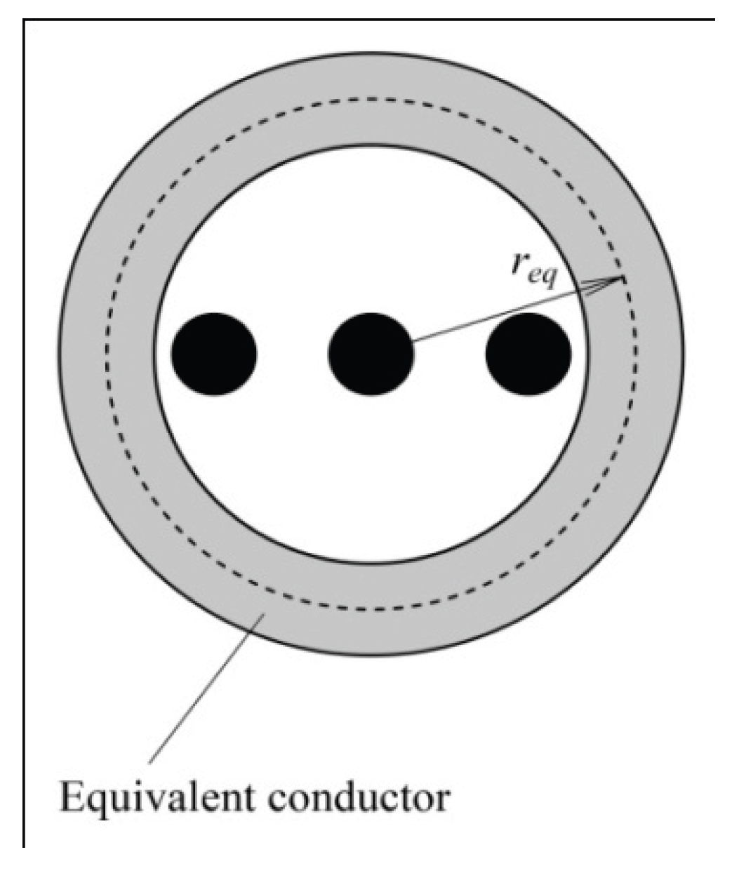
Figure 8.
Cross-section of the cable line completed with actual sheaths [10].
Figure 8.
Cross-section of the cable line completed with actual sheaths [10].
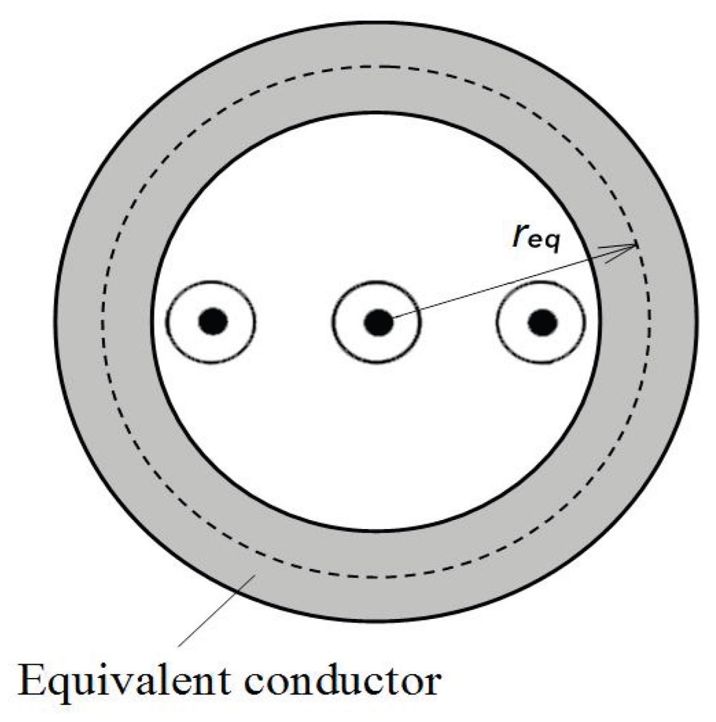
Figure 9.
Phase conductor with current If, and its equivalent sheath.
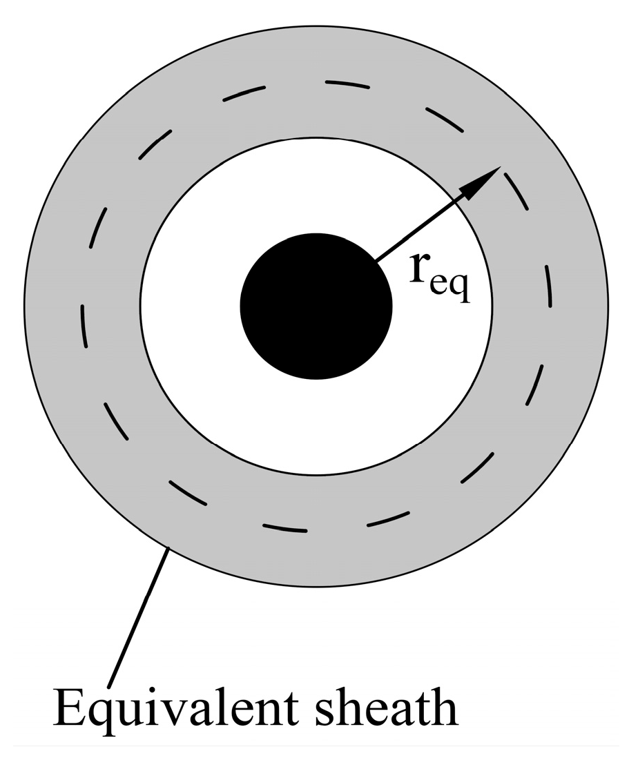
Figure 10.
Cable line with one effective sheath during a ground fault.
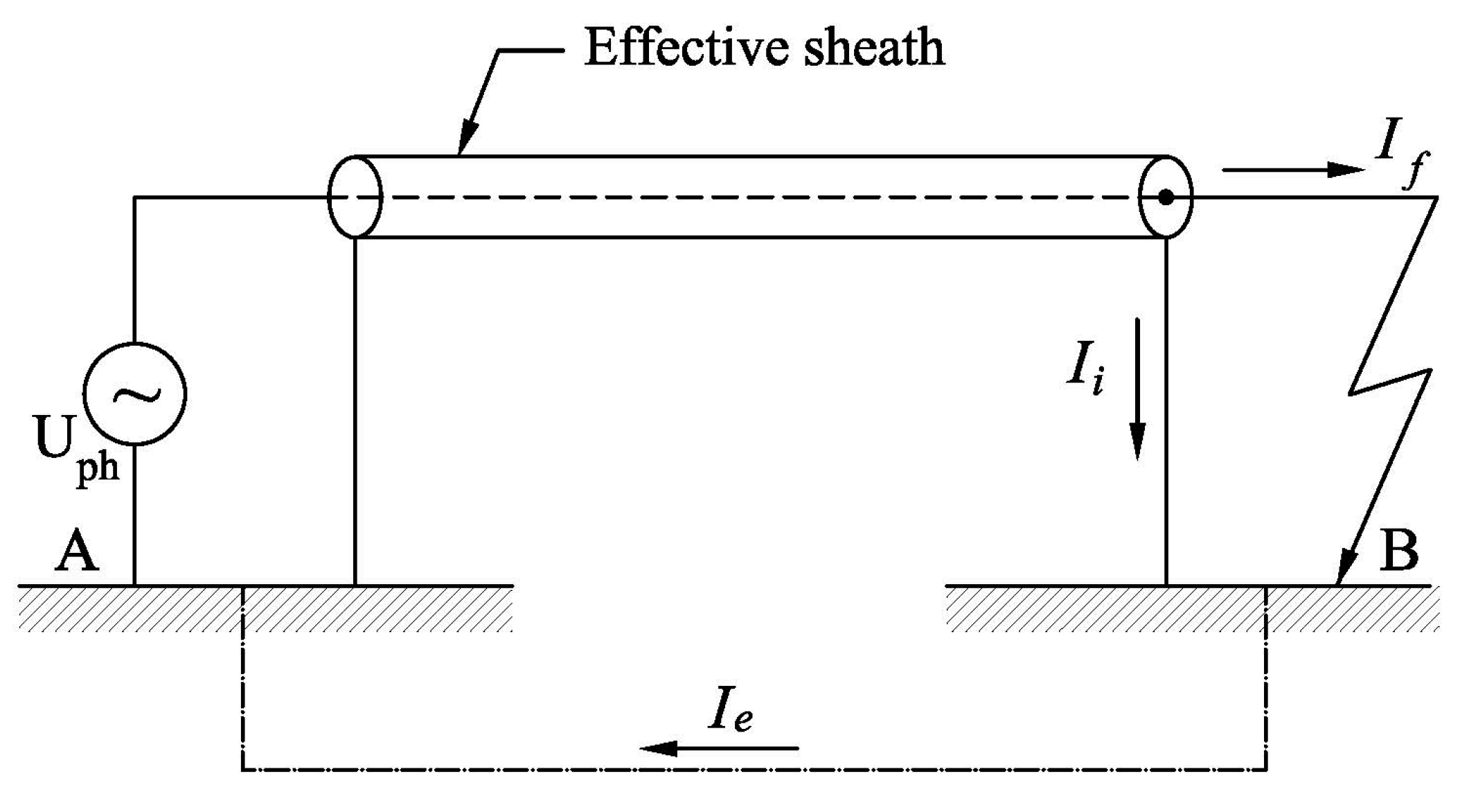
Disclaimer/Publisher’s Note: The statements, opinions and data contained in all publications are solely those of the individual author(s) and contributor(s) and not of MDPI and/or the editor(s). MDPI and/or the editor(s) disclaim responsibility for any injury to people or property resulting from any ideas, methods, instructions or products referred to in the content. |
© 2025 by the authors. Licensee MDPI, Basel, Switzerland. This article is an open access article distributed under the terms and conditions of the Creative Commons Attribution (CC BY) license (http://creativecommons.org/licenses/by/4.0/).
Copyright: This open access article is published under a Creative Commons CC BY 4.0 license, which permit the free download, distribution, and reuse, provided that the author and preprint are cited in any reuse.


