1. Introduction
Additive manufacturing (AM) of polymer tools has opened new possibilities for flexible and cost-effective sheet metal forming, especially in small and medium enterprises (SMEs) and in low-volume or prototype production. Conventional toolmaking based on hardened steel or cast-iron dies is still the standard for high-volume stamping and deep drawing, but it involves long lead times, expensive machining, and limited adaptability once the tooling is finished. In contrast, direct additive tooling, typically based on fused deposition modelling/filament fabrication (FDM/FFF), enables direct fabrication of forming tools from CAD data, with minimal material waste and very low material cost, making it attractive for rapid tooling, design iterations, and short production runs [
1,
2,
3].
The feasibility of using polymer tools in metal forming has been demonstrated in several processes. Durgun investigated FDM-based upper and lower dies for stamping prototype parts from DC04 and S355MC steel, and showed that, for DC04, up to about 100 parts can be produced within the dimensional tolerances, with significant reductions in tool cost and lead time compared to conventional tooling [
2]. Nakamura et al. evaluated plastic tools produced by FDM for both V-bending and deep drawing of steel and aluminium sheets, and highlighted that dimensional accuracy is limited by the low stiffness of the plastic tools, but can be improved by reinforcing the tools with steel bars and by modifying the tool geometry to compensate for elastic deformation and springback. They also showed that plastic dies can be particularly advantageous in deep drawing of softer sheet materials, because they reduce scratching and allow forming without lubrication [
1]. Complementary to these feasibility studies, Kaleem et al. proposed a design criterion for 3D printed polymer tools in metal forming, based on a von Mises failure approach. Their combined FE–experimental analysis provides a practical way for SMEs to assess whether a given polymer tool geometry and material will safely carry the forming load, even when only engineering stress–strain data from standard tensile tests are available [
4].
Beyond bending and deep drawing, polymer-based rapid tooling has been explored for hydroforming, groove pressing, and more complex parts. Prithvirajan et al. used FDM ABS dies as direct rapid tools for metal bellow hydroforming and showed, via combined FEA and experiments, that such dies can successfully form stainless steel bellows in low-volume production. They also demonstrated how low-stress regions in the die can be topologically modified (e.g. by introducing pores or lattice structures) to reduce material consumption, provided that the die strength remains above the critical level [
5]. Tondini et al. evaluated additively manufactured polymer tools in V-bending and groove pressing of 1 mm aluminium sheets. Their results showed that FFF tools reach a steady-state surface condition after a few strokes, and that the combination of springback and elastic deflection of the tools significantly influences the final bend angle; however, the scatter of the resulting geometry is low enough to allow systematic tool corrections toward nominal values [
6]. In a related study, the same group proposed a flexible production concept in which 3D printed PLA tools are used in a multi-feature forming operation, and compared the time and cost of printed tools to conventionally machined tools. They concluded that, for small series and flexible manufacturing, printed tools can be produced overnight at a fraction of the cost, and that PLA tools also offer environmental benefits such as recyclability and reduced need for lubricants [
7].
Additive tooling is not limited to metal forming. Popović et al. presented an integrated use of reverse engineering and FDM for rapid tooling in two-component polymer casting. Based on optical scanning of an existing plastic part, they built and iteratively refined a master CAD model and FDM-printed casting tools. The successful replication of the original gas-handle geometry confirmed that AM-based rapid tooling can shorten development time and reduce cost in small-batch polymer processing when technical documentation is missing [
3]. These studies collectively show that additive tooling has matured into a versatile concept applicable to deep drawing, hydroforming, air bending, groove pressing, and casting, and that it is particularly suitable when flexibility, low investment, and short lead time are more important than tool life in the millions of cycles [
1,
2,
3,
5,
6,
7].
A number of works have focused specifically on bending processes with polymer tools and on the associated stress–strain states. Rehman analysed U- and V-shaped tools made of PLA, combining static structural analysis in ANSYS with experimental V-bending tests. The study confirmed that plastic tools can be used for sheet metal bending with acceptable dimensional accuracy, reduced fixed tooling cost, and reduced material waste, especially in small batches [
8]. Giorleo and Deniz investigated V-bending of 2 mm stainless steel sheets using FFF tools made of nylon reinforced with short carbon fibres. By comparing horizontal and vertical build orientations, they showed that polymer punches and dies undergo measurable permanent deformation away from the working zone, yet are capable of maintaining sheet geometry within 0.5% deviation over multiple cycles [
9]. Zaragoza et al. examined V-die air bending using PC and PLA dies produced by FDM. They performed compression tests on printed samples with different printing strategies, used FE simulations to identify critical tool regions, and carried out repeated bending tests. Their results highlighted the strong influence of printing pattern on tool stiffness, durability and angle repeatability. Among the tested configurations, a 45–90–45° printing pattern for PLA dies provided a particularly stable bending response over many cycles [
10].
At the same time, there has been considerable progress in the mechanical characterization of AM polymers specifically for tool design. Frohn-Sörensen et al. systematically evaluated compressive and flexural properties of different FFF polymers and layer heights, and used the resulting data as input for a cup-drawing case study. Their work illustrates how accurate mechanical characterization of solid-infill specimens can support a more reliable design of DPAT (Direct Polymer Additive Tooling) tools under high forming loads [
11]. However, the mechanical response of printed polymers is not only material-dependent but also highly sensitive to process parameters and internal architecture. Hmeidat et al. quantified the effect of infill patterns on the stiffness, strength, and failure modes of topologically optimized ABS beams in three-point bending, showing up to 22% variation in stiffness and a 426% variation in failure load between different patterns. Their elastic FEA with orthotropic plies captured stiffness trends well, but simple maximum-stress criteria were insufficient to predict strength, underscoring the complexity of failure in printed structures [
12]. El-Deeb et al. studied the influence of nozzle diameter and printing speed on the tensile behaviour of ABS and PLA and found that optimal combinations of large nozzle diameter and moderate speed can significantly improve tensile strength, with PLA generally outperforming ABS but also being more sensitive to process windows [
13].
The nonlinear and anisotropic behaviour of ABS in FDM has been investigated in more detail by Bhuiyan and Khanafer, who combined uniaxial tensile tests at different infill densities with hyperelastic modelling. They showed that Young’s modulus increases exponentially with infill density and that strain at break exhibits a non-monotonic trend, while hyperelastic models such as Mooney–Rivlin and Yeoh can accurately reproduce the observed stress–strain curves. This provides a basis for more realistic constitutive models of printed ABS in FE simulations [
14]. Complementing these generic studies, our research group has carried out extensive experimental work on ABS materials for forming tools. In tensile tests, Delic et al. showed that raster angle, layer thickness, printing velocity, infill pattern, and infill density all significantly affect tensile strength and strain at break, with the most favourable combinations involving a ±45° raster angle, thin layers, and high infill, but these settings substantially increase printing time [
15]. In compression, Delic et al. demonstrated that vertical build orientation, small layer thickness, rectangular infill, and high infill density yield higher compressive strength, which is directly relevant for the predominantly compressive loading of forming tools [
16]. Beyond ABS, Delic et al. also studied Onyx (micro carbon fibre–filled nylon) with and without continuous fibreglass reinforcement. They found that both infill pattern and fibre volume fraction strongly influence tensile properties and stiffness, and that multi-layer reinforcement can significantly improve strength, albeit at the cost of reduced ductility [
17]. Overall, these results confirm that mechanical properties of candidate polymer tool materials are highly process-dependent and must be carefully characterized and selected for each application.
On the modelling side, there is a well-established body of work on numerical simulation of metal forming processes, including springback prediction, but its systematic integration with polymer tooling is still limited. Mandic provided a comprehensive framework for physical and numerical modelling of metal forming, including constitutive modelling, contact behaviour, and validation strategies, which is widely applicable to both conventional tools and additively manufactured [
18]. Aksenov and Kononov demonstrated that numerical simulation of sheet metal forming with plastic tools in
Simufact.forming can accurately capture forming forces, stress distribution in the tool, and the springback of aluminium parts, thereby confirming the feasibility of using 3D printed plastic tools for thin-sheet forming when tool stresses remain below the elastic limit [
19]. Kella and Mallick analysed springback in aluminium/polypropylene/ aluminium sandwich laminates, combining LS-DYNA simulations with experiments and systematically studying the influence of sheet thickness, die and punch radius, and blank holder force. Their work showed how process parameters and laminate design can be tuned to control springback, but focused on metallic/composite sheets with conventional steel tools [
20].
More recently, topology optimization and advanced FE modelling have been applied to polymer tools themselves. Giorleo and Deniz proposed a topology-optimization-based design of polymer bending tools produced by FFF. They used standard polymer tools to identify load conditions, performed topology optimization to reduce tool mass by about 50%, and validated the optimized geometry experimentally. The optimized tools exhibited increased elastic deformation and slightly larger springback (≈2° difference in bending angle), but remained structurally safe and functionally adequate for low-volume production [
21]. Bhatia and Patel, in turn, combined FE simulation and experiments for V-bending with ABS tools, evaluating formability and dimensional accuracy for SS304 and AA6061 sheets and indicating that ABS tools can be loaded up to about 139 MPa in compression with acceptable wear over on the order of 100 parts [
22]. These studies demonstrate that detailed FE modelling of sheet metal forming with polymer tools is feasible and that topology optimization can further improve AM efficiency, but they generally stop at demonstrating feasibility or mass reduction, with limited emphasis on predictive control of springback and on systematic comparison between polymer and steel tools for industrially relevant air-bending operations.
Despite this substantial progress, several important research gaps remain. First, many experimental studies on polymer tools primarily demonstrate feasibility for selected low-volume forming applications, often considering a limited range of bending angles, sheet thicknesses, or materials, while springback compensation is frequently treated empirically rather than through predictive numerical models. Second, although the mechanical behaviour of additively manufactured polymers is known to be strongly influenced by printing parameters, infill characteristics, and reinforcement strategies, this knowledge is only partially transferred into forming simulations. In many cases, material models are derived from simple standardized test specimens and do not fully represent the complex combination of compression, bending, and cyclic loading experienced by forming tools during air bending. Third, fully integrated frameworks that combine systematic material characterization of both sheet metal and polymer tools, finite element simulation accounting for elastic deformation of both components, and high-resolution experimental validation of springback remain scarce for air-bending processes.
This study proposes a comprehensive experimental–numerical framework for the analysis of air bending of sheet metal with additively manufactured polymer tools. The focus is placed on accurate characterization of material behaviour, reliable prediction of springback, and numerical determination of tool angle compensation required to achieve the target bending geometry. The proposed methodology integrates uniaxial tensile testing, controlled air-bending experiments, finite element modelling, and optical angle measurement, providing a consistent basis for validation of numerical predictions.
The presented approach systematically combines experiments performed with conventional steel tools and numerical simulations using rigid and deformable tools to establish a validated reference model of the air-bending process. This validated framework is subsequently extended to simulations and experiments with additively manufactured ABS tools, enabling assessment of the influence of reduced tool stiffness on the resulting bending angle and verification of the proposed springback compensation strategy.
Building on previous investigations of the tensile and compressive behaviour of FDM-printed ABS under varying raster orientations, infill patterns, densities, and layer thicknesses [
16,
17], the relevant mechanical response of the tool material is characterized for the stress state encountered in air bending. These data are used to calibrate constitutive models for the polymer tools, while established elastoplastic models are adopted for mild steel sheets, following best practices in numerical simulations of sheet metal forming [
21].
Finite element analyses of the air-bending process are performed with explicit consideration of the elastic–plastic response of the sheet material and the influence of tool stiffness on the bending process, enabling accurate prediction of sheet springback. The numerical results are validated through controlled bending experiments and high-resolution optical measurements of the bent geometry. Through this integrated approach, the study provides a validated basis for numerical springback prediction and tool angle compensation, and establishes methodological guidelines for the rational design and assessment of additively manufactured polymer tools for low-force air-bending applications.
2. Materials and Methods
2.1. Sheet Material
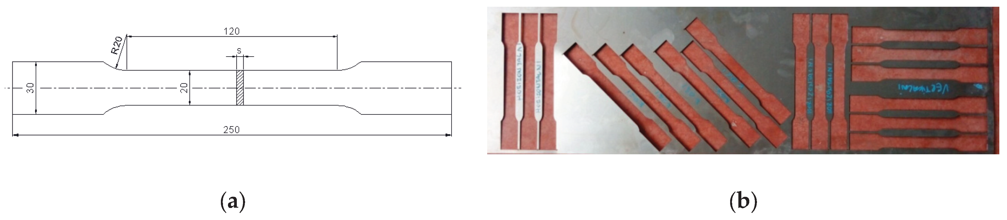
The sheet material investigated in this study was low-carbon cold-rolled steel DC04, chosen for its good formability and stable mechanical response, which make it suitable for systematic experimental and numerical analysis of bending processes. The sheets were supplied in cold-rolled condition with a nominal thickness of t = 0.8 mm.
In order to ensure accurate numerical simulation of the air-bending process and reliable springback prediction, the mechanical behaviour of the sheet material was characterized experimentally through uniaxial tensile testing. Uniaxial tensile tests were conducted at room temperature in accordance with ISO 6892-1. Standard flat specimens were prepared by laser cutting, with three different orientations relative to the rolling direction (0°, 45°, and 90°), in order to capture potential anisotropy effects. The specimen geometry and cutting directions are shown in
Figure 1.
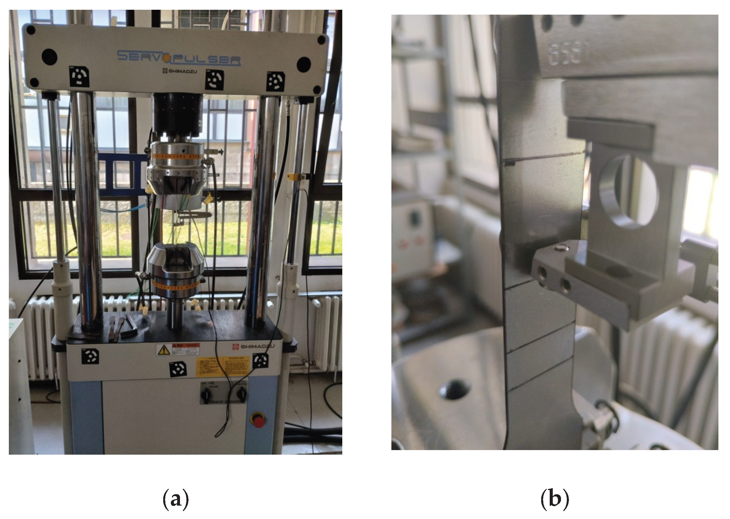
The experiments were performed on a Shimadzu universal testing machine located at the Faculty of Engineering. The testing system was equipped with pneumatic grips and a mechanical extensometer with a gauge length of 50 mm, enabling accurate measurement of axial strain during loading. A photograph of the testing setup and the mounted specimen is shown in
Figure 2.
The crosshead speed was determined according to the recommendations of ISO 6892-1, based on the selected gauge length and target strain rate in the elastic–plastic transition region. Following the standard procedure and the prescribed strain rate range, a nominal crosshead speed of 2 mm/min was adopted for all experiments. This ensured stable deformation conditions and reliable identification of yield and hardening behaviour.
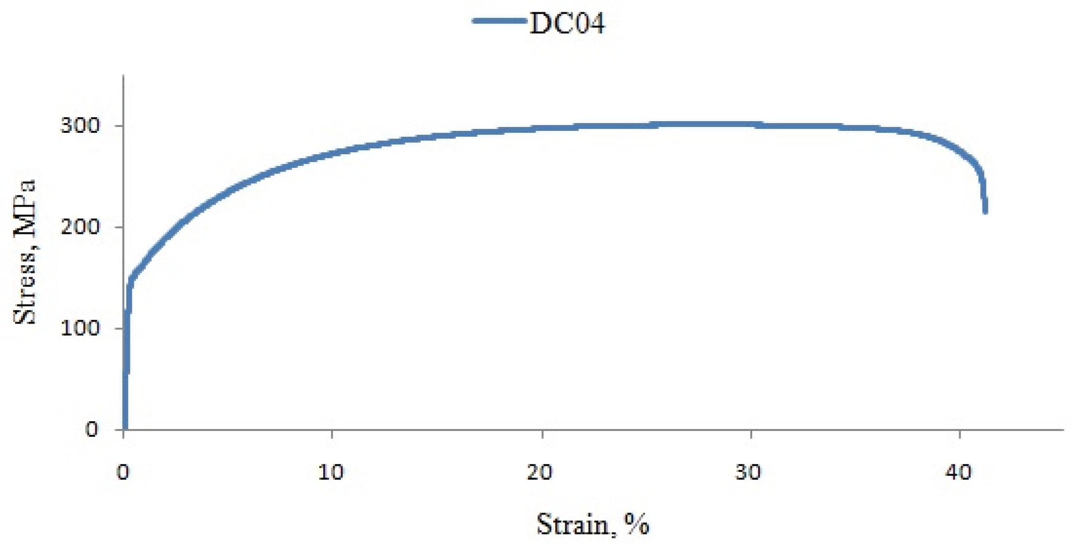
Representative engineering stress–strain curve obtained from the tensile tests is presented in
Figure 3. The corresponding mechanical properties, including yield stress R
p, ultimate tensile strength R
m, and total elongation at fracture
A120 (with L
0 = 120 mm) are summarized in
Table 1. The results show a moderate dependence of yield stress on specimen orientation, with the highest yield stress observed for specimens cut along the rolling direction. In contrast, the ultimate tensile strength remained nearly identical for the 0° and 45° orientations and slightly lower for specimens cut at 90°, indicating limited anisotropy in tensile strength.
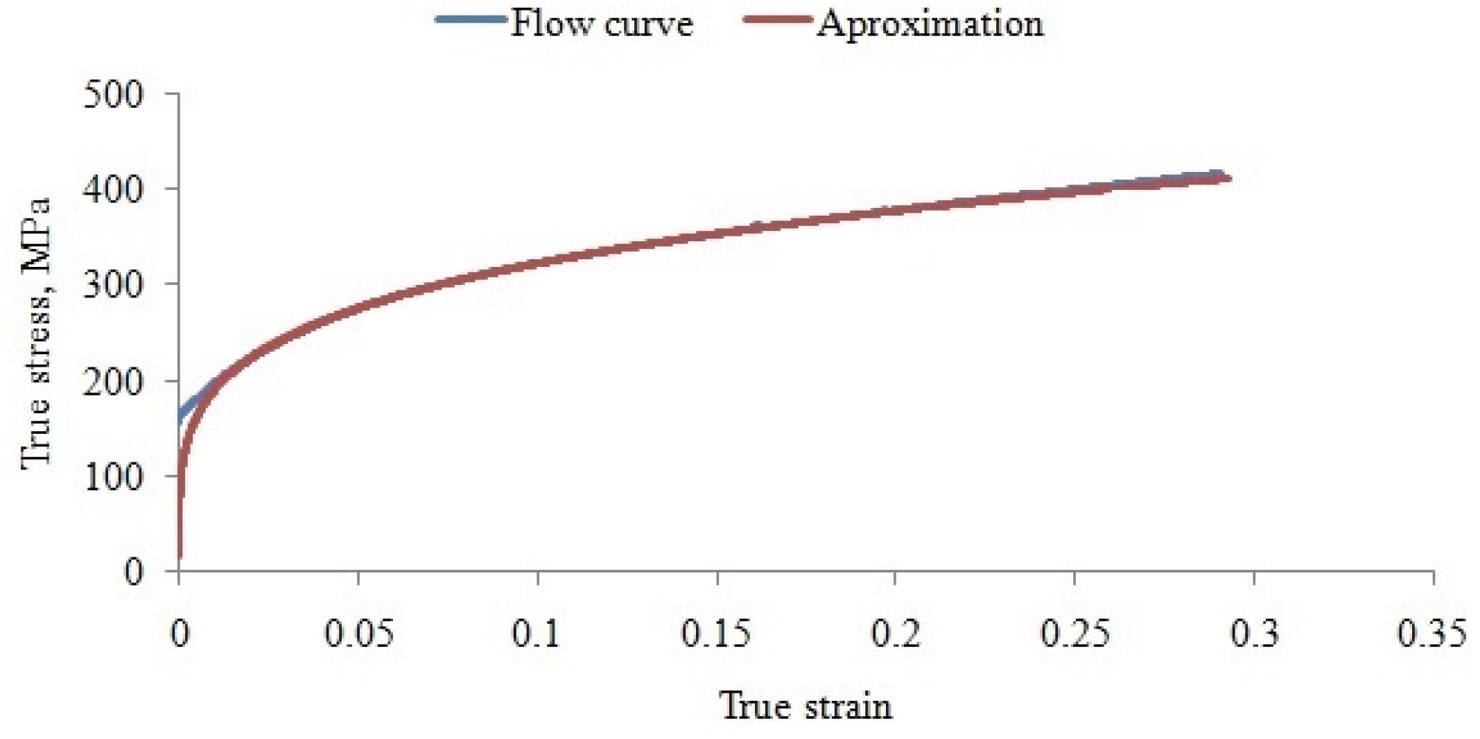
For numerical modelling of the air-bending process, the flow stress curve of DC04 was determined experimentally from the tensile test data. The analysis focused on the region of homogeneous plastic deformation, between the onset of yielding and the maximum tensile force. The experimentally obtained true stress–true strain data were approximated using a least-squares fitting procedure, implemented in Statistica and Microsoft Excel. The resulting analytical representation of the flow curve is shown in
Figure 4 and can be expressed in power-law form as:
The quality of the approximation was confirmed by a high correlation coefficient (R2=0.996), indicating excellent agreement between experimental data and the fitted model.
The identified flow curve parameters were used directly as input for the finite element simulations of the air-bending process. For springback prediction, the sheet material was modelled as elastoplastic with isotropic hardening, which is a commonly adopted and well-established approach in numerical simulations of sheet metal forming processes [
18]. This material characterization provided a reliable basis for coupling experimental bending tests with finite element analysis and for accurately predicting elastic springback of the sheet and the resulting final bent geometry.
2.2. Tool Material and Additive Manufacturing
The bending tools used in this study were manufactured from acrylonitrile–butadiene–styrene (ABS) using fused deposition modelling (FDM) and 3D printer MakerBot Replicator 2X. ABS was selected due to its widespread availability, low material cost, good printability, and a favourable balance between stiffness and ductility, which makes it suitable for low-force and low- to medium-volume forming applications.
The mechanical behaviour of FDM-printed ABS is strongly dependent on printing parameters such as raster angle, layer thickness, infill pattern, infill density, and build orientation. A comprehensive experimental investigation of these effects, including tensile and compressive testing and fracture analysis, was previously conducted by the authors and reported in detail in [
15].
In that study, it was demonstrated that raster orientation, layer thickness, and infill architecture have a pronounced influence on tensile strength, strain at break, and fracture mode of ABS specimens. In particular, raster angles of ±45°, reduced layer thickness, and high infill densities were shown to provide improved mechanical performance, although at the expense of increased printing time. Complementary compression tests further indicated that vertical build orientation, small layer thickness, and rectangular infill patterns yield higher compressive strength, which is directly relevant for the predominantly compressive loading conditions encountered in air-bending tools.
In addition to the previously published experimental investigation [
15], a statistical analysis was performed in order to quantitatively assess the relative influence of selected FDM printing parameters that are particularly relevant for bending tools, namely raster orientation and layer thickness. While the initial analysis of tensile results was based on averaging procedures, a more rigorous evaluation of parameter significance requires the application of dedicated statistical methods.
For this purpose, the Taguchi method was employed. For each experimental run, the signal-to-noise (S/N) ratio was calculated and used as the objective function for optimization. The S/N ratio represents a logarithmic transformation of the output response and enables robust comparison of parameter effects by reducing the influence of random variability. Since the objective was to maximize tensile strength, the “larger-is-better” criterion was adopted.
A Taguchi L9 orthogonal array was selected, considering two control factors, raster orientation (U) and layer thickness (s), each at three levels. The experimental plan and the corresponding tensile strength values and S/N ratios are summarized in
Table 2. Statistical analysis was carried out using Minitab [
23].
Mean S/N values were calculated for each factor level, and the Delta value was determined as the difference between the maximum and minimum mean S/N ratios for a given factor. The factor with the highest Delta value was ranked as the most influential. The results clearly indicate that raster orientation has a stronger influence on tensile strength than layer thickness. Specifically, the raster orientation factor exhibited a Delta value of 0.79, compared to 0.42 for layer thickness, corresponding to ranks 1 and 2, respectively.
To further quantify the relative importance of the parameters, an analysis of variance (ANOVA) was performed on the S/N ratios. The percentage contribution of each factor was calculated based on the ratio of its sum of squares to the total sum of squares. The analysis showed that raster orientation accounts for approximately 71.6% of the total variation in tensile strength, whereas layer thickness contributes 21.7%. These results confirm that raster orientation is the dominant parameter governing the tensile behaviour of FDM-printed ABS, which is particularly important for bending tools subjected to combined compressive and bending loads.
Based on these findings, ABS was adopted in the present work as a representative polymer tool material, and printing parameters were selected to ensure sufficient stiffness and load-bearing capacity while maintaining reasonable manufacturing time. The previously established material characterization [
15] therefore serves as the mechanical basis for the numerical modelling and experimental evaluation of additively manufactured bending tools presented in this study.
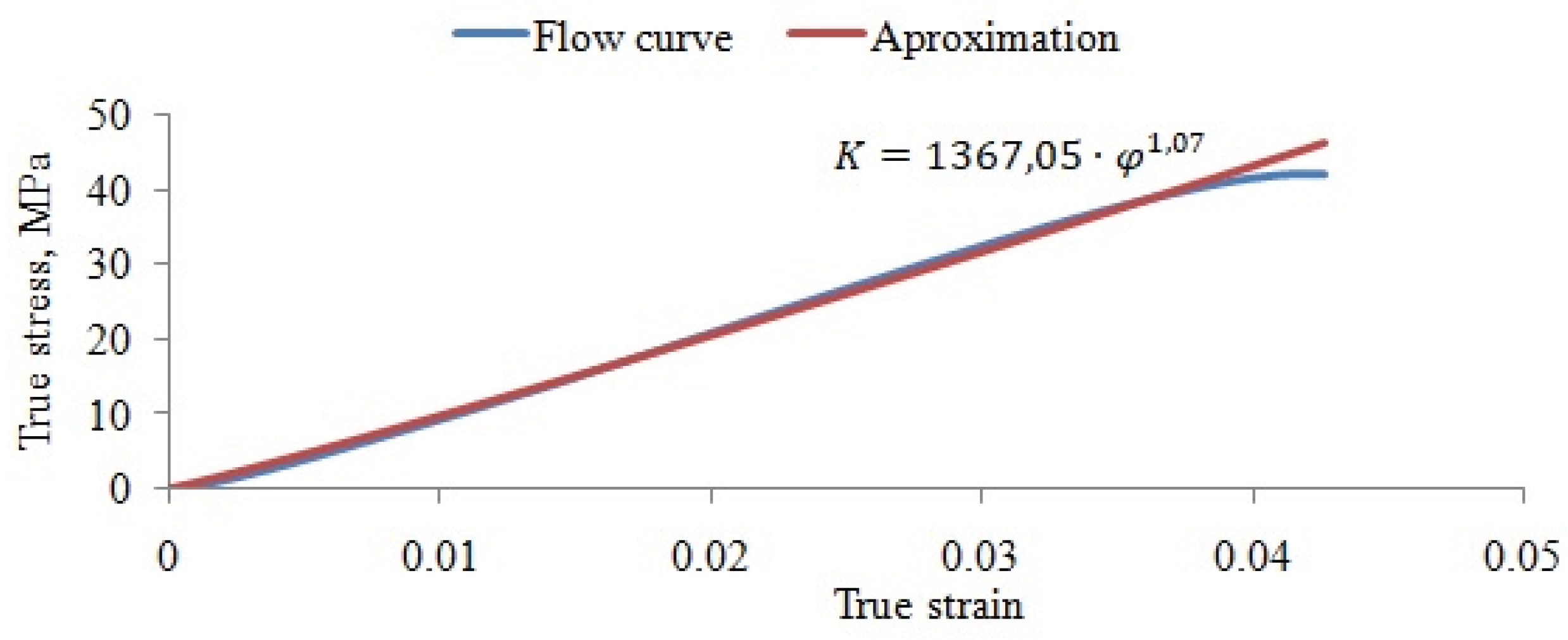
For finite element modelling of air bending with polymer tools, a constitutive description of the ABS material was required. The analysis focused on specimens printed with 100% infill, a ±45° raster orientation, and a layer thickness of 0.2 mm, which represents a commonly used and mechanically favourable printing configuration for functional tools. Printing speed was kept constant, as previous analysis showed that its influence on mechanical properties is negligible compared to raster orientation and layer thickness. The experimentally obtained tensile stress–strain curves indicate a predominantly a quasi-brittle mechanical response characterized by limited plastic deformation prior to fracture. The following mechanical properties were obtained from tensile testing: yield stress Rp = 38.24 MPa, ultimate tensile strength Rm = 38.98 MPa and fracture strain εf= 6.67%.
Based on the results of tensile testing, the flow stress behaviour of ABS was described using a power-law hardening model of the form σ=Cφ
n, where σ is the true stress, φ is the true plastic strain, C is the strength coefficient, and n is the strain-hardening exponent. Using least-squares fitting of the true stress–true strain data in the homogeneous deformation region, the material constants were identified as: C=1314.59 and n=1.073. The resulting flow stress curve and its analytical approximation are shown in
Figure 5. The identified parameters provide an adequate description of the nonlinear mechanical response of FDM-printed ABS and were directly implemented in the finite element simulations of the air-bending process.
This combined experimental and statistical characterization ensures that the constitutive model used for the polymer tools reflects both the dominant influence of printing parameters and the actual stress–strain behaviour relevant to tool loading conditions in air bending.
2.3. Tool Geometry and Air-Bending Configuration
2.3.1. Specimen Geometry
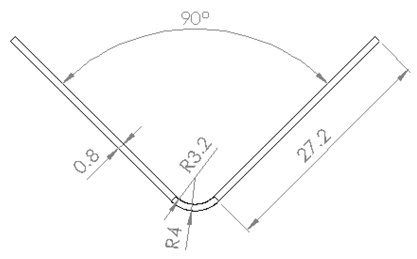
Prior to tool design and experimental planning, the admissible bending radius range and the developed blank length were estimated in order to define the target geometry of the V-bent specimen. The nominal dimensions of the bent part are shown in
Figure 6. This geometry was selected to ensure a uniform bending zone and to allow reliable comparison between experimental measurements and numerical predictions under plane-strain conditions. The specimen dimensions are representative of typical laboratory-scale air-bending tests and are sufficiently large to avoid edge effects while remaining compatible with the available tooling and testing machine constraints. The air-bending experiments were performed on rectangular sheet specimens made of DC04 steel, with dimensions 35×60 mm and a nominal thickness of 0.8 mm.
2.3.2. Air-Bending Tool Configuration
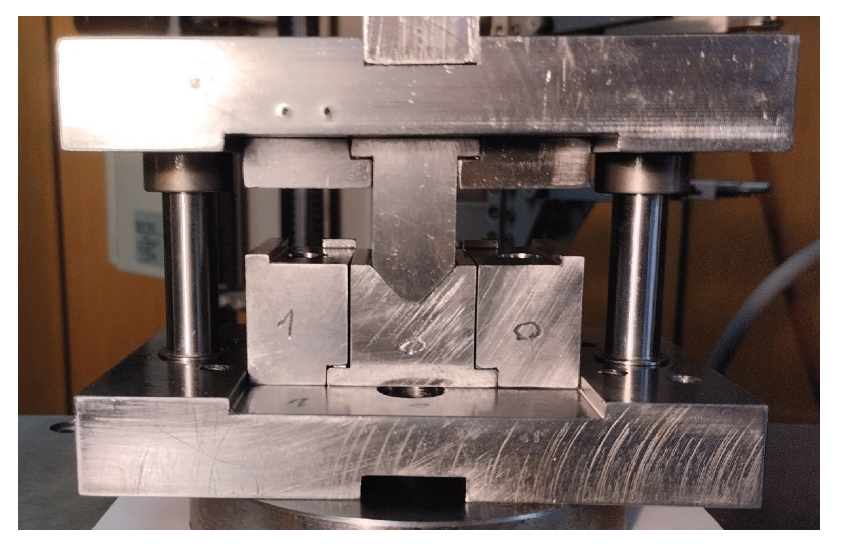
A dedicated modular air-bending tool was used in the experiments, mounted on a universal testing machine (Zwick/Roell Z100). The tool was designed to ensure accurate alignment of the punch, die, and sheet specimen, as well as repeatable boundary conditions during bending. A representative view of the tool mounted on the testing machine is shown in
Figure 7.
The modular tool concept enables rapid replacement of conventional steel punch and die elements with FDM-manufactured ABS inserts, allowing direct experimental comparison of metal and polymer tools under identical loading and boundary conditions. Air-bending experiments with metallic punch and die inserts were conducted to establish a reference springback response of the sheet material under rigid tooling conditions. These experiments served to validate the finite element model of the process and to determine the required compensation angle for achieving the target bend geometry. Based on this validated numerical framework, additively manufactured ABS tools with compensated geometries were subsequently designed and tested, allowing verification of the predicted bending angle under identical forming conditions.
2.3.3. Loading Scheme and Process Parameters
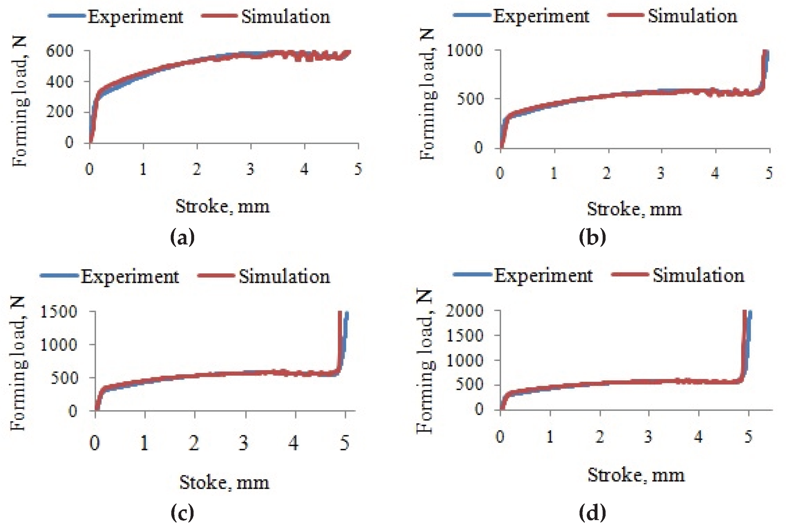
The air-bending experiments were conducted under force-controlled conditions, with the maximum forming force prescribed as the primary control parameter. Four force levels were selected: 600 N, 1000 N, 1500 N, and 2000 N. This range was chosen to cover low to moderate forming severities, which are particularly relevant for polymer-based bending tools, where excessive forming forces must be avoided to prevent tool damage. The selected loading scheme provides a controlled framework for identifying the relationship between forming force and springback angle, which is essential for validation of the numerical model and for subsequent determination of springback compensation strategies. The maximum force was defined in the TestXpert control software of the testing machine. Once the prescribed force level was reached, punch motion was stopped and unloading was initiated, allowing elastic recovery of the sheet. All experiments were carried out at a constant crosshead speed of 5 mm/min, ensuring quasi-static conditions and stable force–displacement response.
2.4. Finite Element Modelling of Air Bending
Finite element simulations of the one-angle air-bending process were performed using the commercial software Simufact.forming [
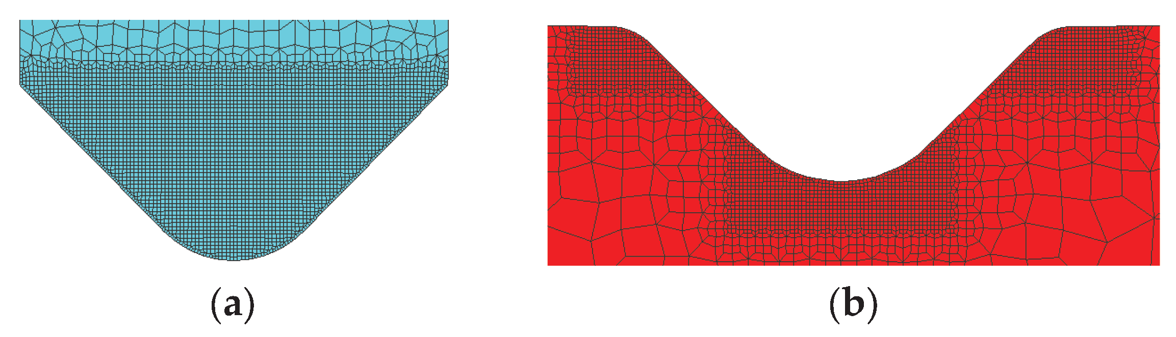
24], which employs the MSC Marc solver. The numerical modelling was carried out in two stages: first using rigid tools and subsequently using deformable tools, in order to assess the influence of tool elastic deflection on springback behaviour. For simulations involving deformable tools, a finite element mesh was also generated for the punch and die. The tools were discretized using an advancing front quadrilateral mesh with Quad 11 elements. A nominal element size of 2 mm was adopted for the tool bodies. In order to accurately capture local stress and deformation gradients in regions of intensive tool–sheet interaction, the mesh was locally refined in the contact zones by a refinement factor of four. This approach ensured sufficient numerical accuracy in the prediction of elastic tool deformation while maintaining reasonable computational efficiency.
Material anisotropy of the sheet was taken into account by defining the rolling direction and anisotropy coefficients r=1,54. The Hill anisotropic yield criterion was employed.
The bending process was modelled as a 2D planar problem, which is commonly adopted for air bending due to the constant cross-section along the bending length. The sheet was discretized using quadrilateral finite elements generated with an advancing-front meshing strategy. An element size of 0.15 mm was adopted in the bending zone to accurately capture strain gradients.
Contact between the sheet and the tools was modelled using a Coulomb friction law, with a friction coefficient of 0.1, selected from the Simufact material library (sheet_medium condition). All simulations were performed at room temperature (20 °C), consistent with the experimental conditions.
2.5. Springback Evaluation
2.5.1. Numerical Springback Evaluation
Springback in the numerical simulations was evaluated after complete unloading and removal of the tools. The total strain state, consisting of elastic and plastic components, was monitored during the unloading phase. Tool removal and workpiece release were defined using the Release dies attached to press and Release workpiece from stationary dies options. Elastic recovery was simulated incrementally over ten unloading steps to improve numerical stability.
The deformed sheet geometry after unloading was exported in STL format and evaluated in CAD software to determine the predicted bending angle of the virtual bent part. These numerical predictions were later compared with experimental measurements to verify the accuracy of the material model and boundary conditions.
This numerical procedure enables direct assessment of elastic recovery as a function of forming force and provides a quantitative basis for comparison with experimental measurements.
2.5.2. Experimental Springback Measurement by Optical 3D Scanning
Experimental evaluation of springback was performed using optical 3D scanning based on structured light projection. A DAVID SLS-2 scanner was employed, consisting of a projector and camera system that reconstructs object geometry from projected light patterns [
25]. Prior to scanning, the scanner was calibrated using a reference calibration panel, and the surfaces of the bent sheet specimens were lightly matted to improve optical contrast. The specimens were scanned from multiple orientations, and the resulting point clouds were processed in dedicated inspection software.
The bending angle was determined by extracting a cross-section from the point cloud and fitting reference lines to the planar regions of the sheet legs. This non-contact measurement approach provides high repeatability and sufficient accuracy for springback assessment and for validation of numerical predictions. The performance characteristics of the DAVID structured-light scanning system have been reported in the literature and are suitable for sheet-metal metrology applications.
4. Discussion
The present study aimed to develop and validate an integrated experimental–numerical framework for air bending of sheet metal using additively manufactured polymer tools, with particular emphasis on springback prediction and tool angle compensation. The discussion below interprets the obtained results in the context of previous studies and highlights their broader implications for additive tooling in bending operations.
4.1. Validation of the Experimental–Numerical Framework
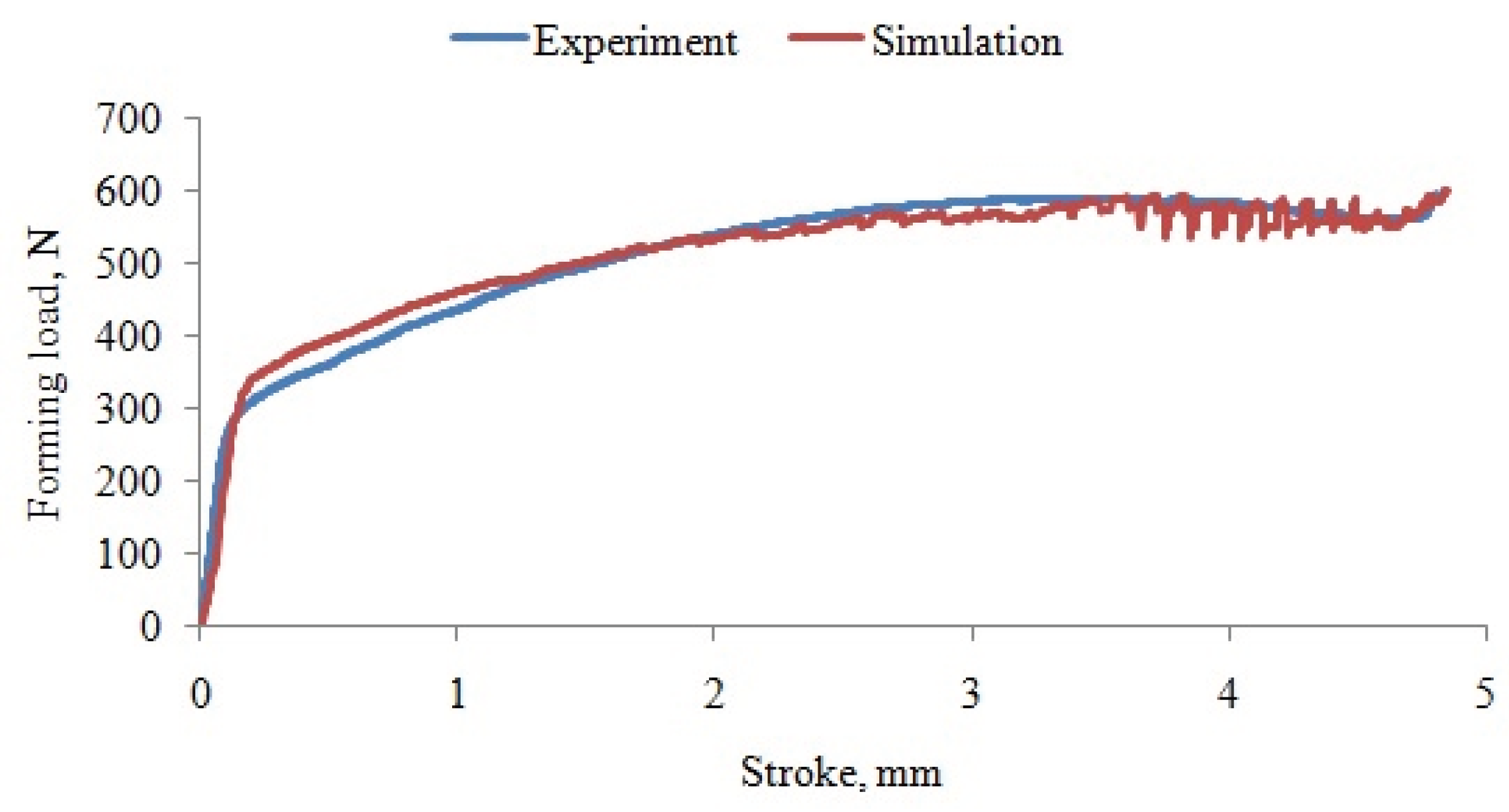
The comparison between experimental results obtained with conventional steel tools and finite element simulations using rigid tools demonstrated very good agreement in terms of force–displacement response and bending angle after elastic unloading. The deviations between experimentally measured and numerically predicted bending angles ranged from 0.46% to 1.31% for all investigated forming loads, with the smallest deviation observed at the lowest force level of 600 N. These results confirm that the adopted constitutive models, contact definitions, and unloading strategy provide an accurate representation of the air-bending process. The observed level of agreement is consistent with previous numerical studies on springback prediction in air bending, which emphasize the importance of reliable material characterization and controlled elastic unloading procedures.
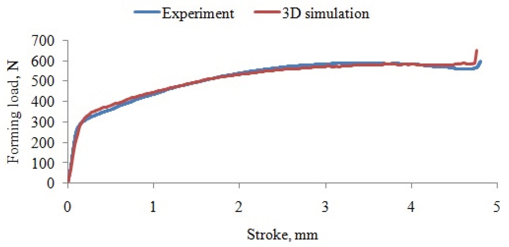
The extension of the numerical analysis to deformable steel tools further confirmed that elastic deformation of the tools has a negligible influence on the final bending angle within the investigated force range. The predicted bending angle after elastic unloading obtained from the two-dimensional simulation with deformable tools was 96.20°, corresponding to a deviation of only 0.32% with respect to the experimentally measured value. The three-dimensional simulation with deformable tools yielded a bending angle of 96.28°, resulting in a deviation of 0.41%. These results demonstrate that the 2D finite element model with deformable tools provides the smallest deviation from experimental measurements among the investigated numerical approaches, while requiring significantly lower computational effort than full 3D simulations. This confirms that air bending of thin sheets can be reliably treated as a planar process for the purpose of springback prediction and tool angle compensation.
4.2. Implications for Springback Compensation
The numerical investigation of springback compensation demonstrated that systematic variation of punch and die angles enables accurate control of the final bending angle without relying on empirical trial-and-error adjustments. The identified optimal tool configurations resulted in predicted bending angles very close to the target value of 90°, with deviations well within typical industrial tolerances. Experimental verification using compensated steel tools confirmed the reliability of the numerical predictions, with average angle deviations of approximately 0.4%, which is substantially lower than the commonly accepted ±1° tolerance in sheet metal bending.
These results highlight the importance of combining validated numerical models with controlled experiments for springback compensation. Unlike many previous studies where compensation strategies are applied empirically, the present approach provides a rational and transferable methodology that can be applied to different materials, tool geometries, and forming conditions.
4.3. Performance of Additively Manufactured ABS Tools
Numerical simulations performed prior to manufacturing the polymer tools demonstrated that ABS tools with compensated angles can safely withstand the applied forming loads, with stress and deformation levels remaining below critical values. The experimental air-bending tests using additively manufactured ABS tools confirmed these predictions: no visible damage or excessive deformation of the tools was observed, and the resulting bending angles showed good repeatability across multiple experiments.
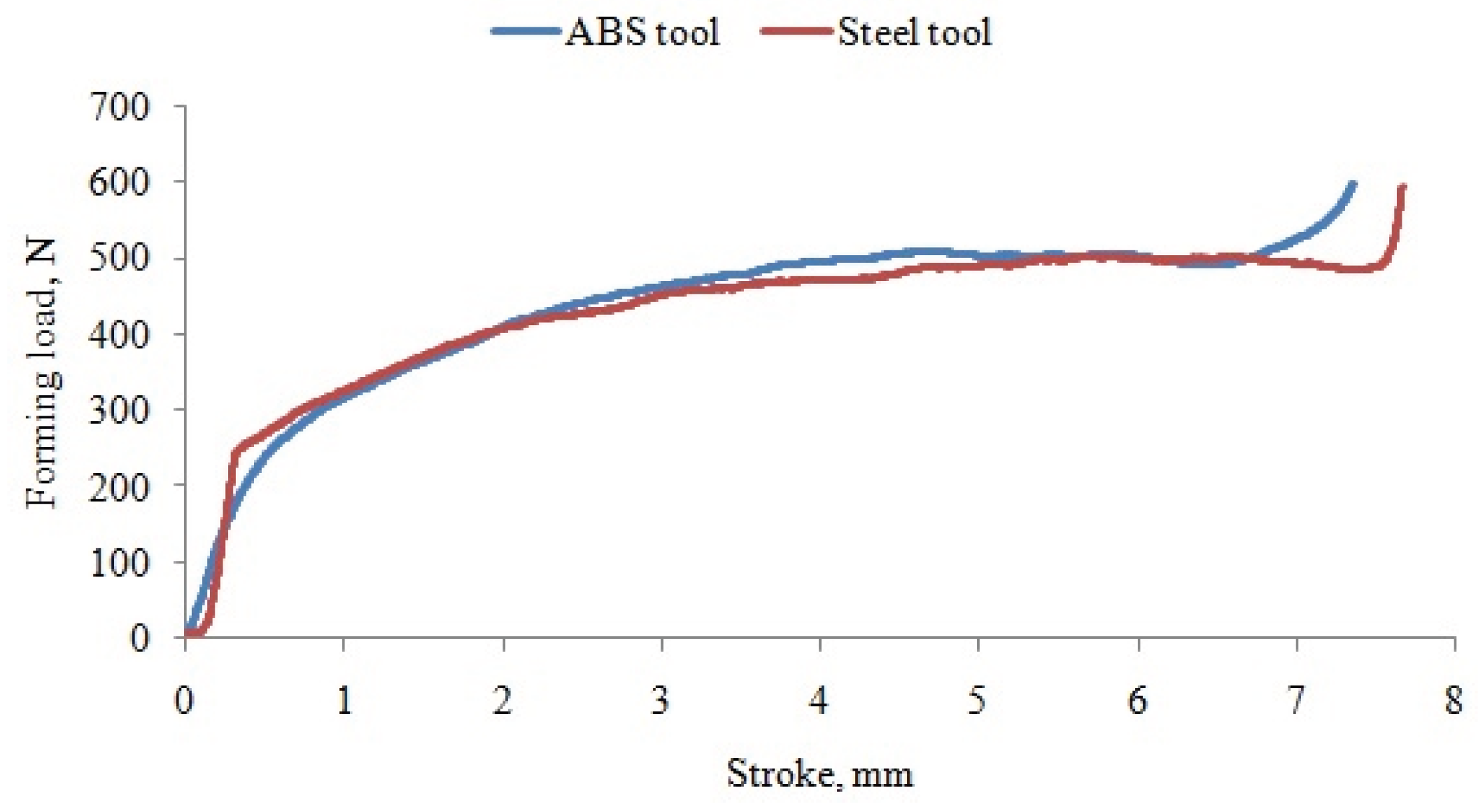
The comparison between metal and ABS tools revealed slightly larger deviations in force–displacement curves and bending angles for the polymer tools, which can be attributed primarily to their lower structural stiffness compared to steel tools, manufacturing tolerances inherent to the FDM process, and friction effects in the guiding system. Nevertheless, the average deviation between experimentally measured and numerically predicted bending angles for ABS tools remained below 1%, demonstrating that the validated numerical framework is capable of accurately predicting sheet springback and the resulting final bend angle even when additively manufactured polymer tools are used.
In comparison with previous feasibility-focused studies on polymer bending tools, the present work goes beyond demonstrating that polymer tools “work” and instead provides a predictive framework for tool design and compensation. This represents an important step toward more systematic and reliable use of additive tooling in bending operations.
4.4. Limitations and Directions for Future Research
Although the proposed methodology has been successfully validated for ABS tools under low forming forces, several aspects warrant further investigation. First, the current study focused on fully solid polymer tools to ensure sufficient stiffness and strength. Future work should explore the application of topology optimization to reduce material consumption and printing time while maintaining acceptable tool stiffness and dimensional accuracy. The numerical stress and deformation data obtained in this study provide a solid basis for such optimization.
Second, the present validation was performed under controlled laboratory conditions using a limited range of forces and sheet thickness. Extending the methodology to more complex bending sequences, higher force levels, and different sheet materials would further clarify the applicability limits of polymer tools. In particular, validation on industrial press brakes and multi-operation bending processes would provide valuable insight into the robustness of the proposed approach under realistic production conditions.
Finally, further refinement of constitutive models for additively manufactured polymers, including anisotropy, rate dependence, and damage evolution, would improve the predictive capability of numerical simulations, especially for long-term tool durability and repeated loading scenarios.
Figure 1.
Specimen geometry (a) and cutting directions (b).
Figure 1.
Specimen geometry (a) and cutting directions (b).
Figure 2.
Testing setup: (a) Shimadzu universal testing machine; (b) mounted specimen.
Figure 2.
Testing setup: (a) Shimadzu universal testing machine; (b) mounted specimen.
Figure 3.
Stress–strain curve for DC04 (rolling direction).
Figure 3.
Stress–strain curve for DC04 (rolling direction).
Figure 4.
Flow curve for DC04.
Figure 4.
Flow curve for DC04.
Figure 5.
Flow curve for FDM-printed ABS.
Figure 5.
Flow curve for FDM-printed ABS.
Figure 6.
Nominal dimensions of the bent part.
Figure 6.
Nominal dimensions of the bent part.
Figure 7.
Air-bending tool mounted on the testing machine Zwick Roell Z100.
Figure 7.
Air-bending tool mounted on the testing machine Zwick Roell Z100.
Figure 8.
Sheet specimen before and after air-bending.
Figure 8.
Sheet specimen before and after air-bending.
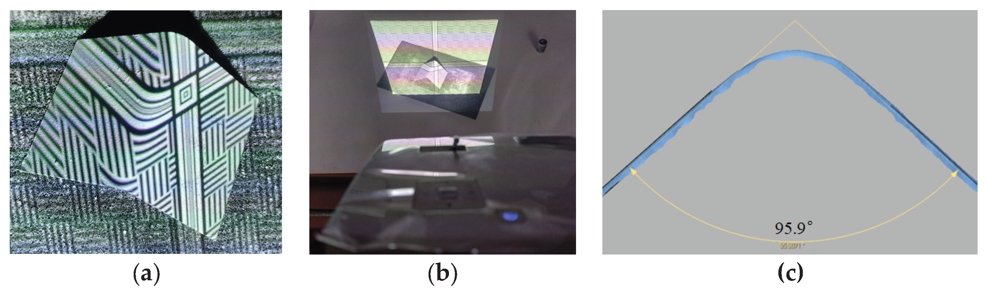
Figure 9.
Optical 3D scanning of the bent specimen: (a) matted bent specimen; (b) David SLS-2 scanning; (c) cross section of point cloud and reference lines for sheet legs.
Figure 9.
Optical 3D scanning of the bent specimen: (a) matted bent specimen; (b) David SLS-2 scanning; (c) cross section of point cloud and reference lines for sheet legs.
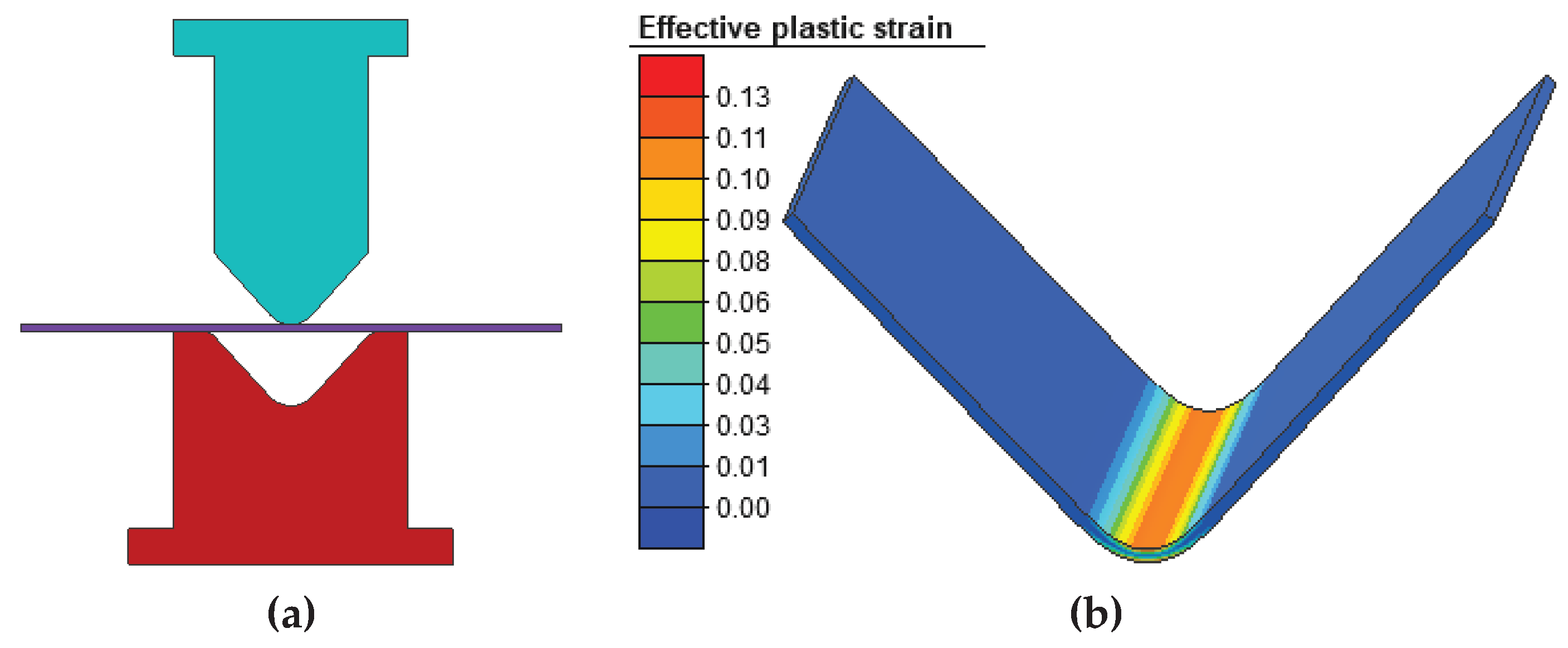
Figure 10.
Numerical simulation of the air-bending process with rigid tools: (a) finite element model and boundary conditions; (b) deformed sheet after unloading with distribution of effective plastic strain.
Figure 10.
Numerical simulation of the air-bending process with rigid tools: (a) finite element model and boundary conditions; (b) deformed sheet after unloading with distribution of effective plastic strain.
Figure 11.
Experimental and numerical force–displacement curves with limited forming load: (a) 600 N; (b) 1000 N; (c) 1500 N; (d) 2000 N.
Figure 11.
Experimental and numerical force–displacement curves with limited forming load: (a) 600 N; (b) 1000 N; (c) 1500 N; (d) 2000 N.
Figure 12.
Locally refined finite element mesh (refinement boxes) applied to: (a) the punch and (b) the die.
Figure 12.
Locally refined finite element mesh (refinement boxes) applied to: (a) the punch and (b) the die.
Figure 13.
Force–displacement response obtained from the numerical simulation with deformable tools, maximum forming force 600 N (compared with experimental diagram).
Figure 13.
Force–displacement response obtained from the numerical simulation with deformable tools, maximum forming force 600 N (compared with experimental diagram).
Figure 14.
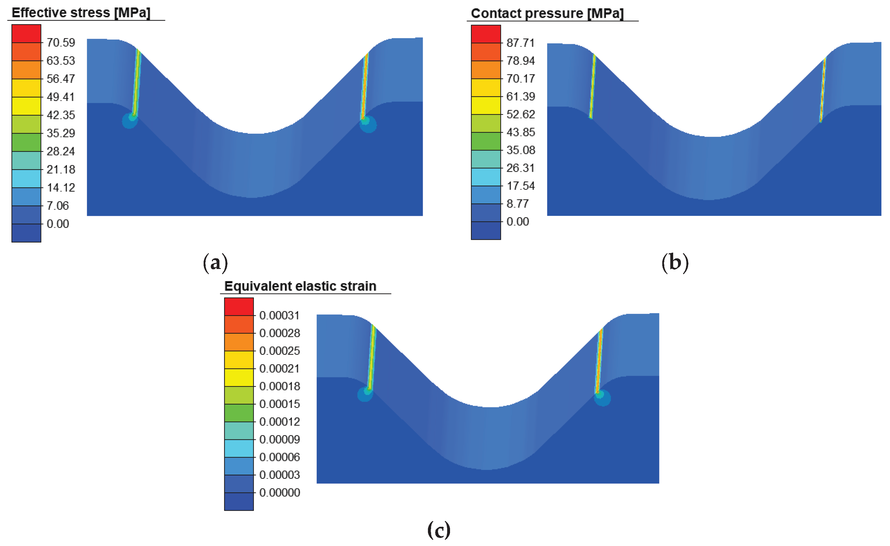
Distribution of results on the deformable die at a maximum forming force of 600 N: (a) equivalent (von Mises) stress; (b) contact pressure; (c) elastic deformation.
Figure 14.
Distribution of results on the deformable die at a maximum forming force of 600 N: (a) equivalent (von Mises) stress; (b) contact pressure; (c) elastic deformation.
Figure 15.
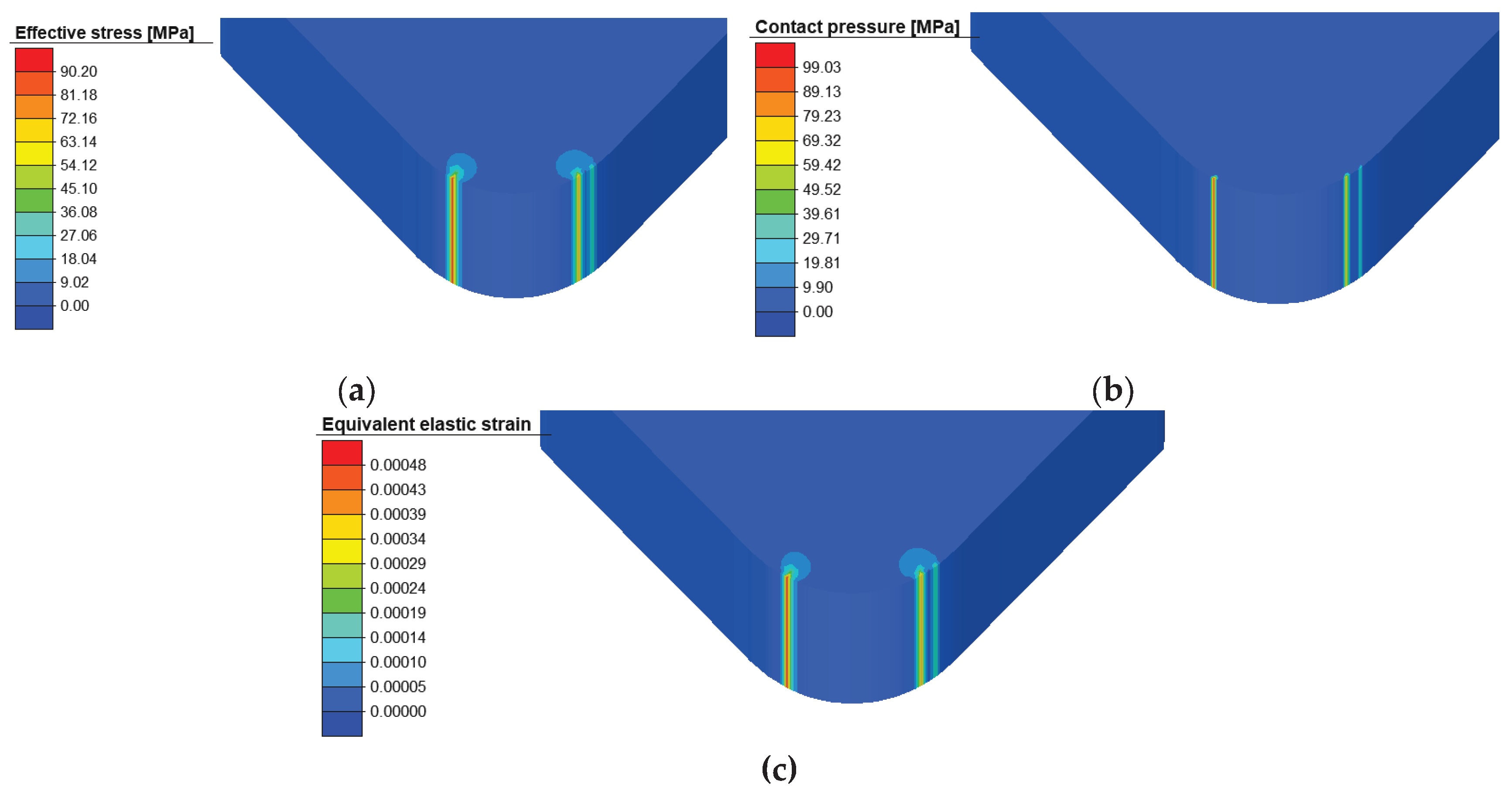
Distribution of results on the deformable punch at a maximum forming force of 600 N: (a) equivalent (von Mises) stress; (b) contact pressure; (c) elastic deformation.
Figure 15.
Distribution of results on the deformable punch at a maximum forming force of 600 N: (a) equivalent (von Mises) stress; (b) contact pressure; (c) elastic deformation.
Figure 16.
Force–displacement curve obtained from 3D numerical simulation (compared with experimental curve).
Figure 16.
Force–displacement curve obtained from 3D numerical simulation (compared with experimental curve).
Figure 17.
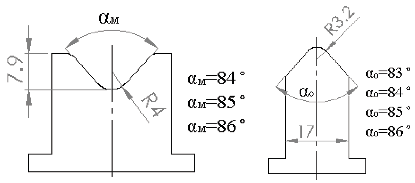
Geometry of the punch and die used for numerical springback compensation analysis.
Figure 17.
Geometry of the punch and die used for numerical springback compensation analysis.
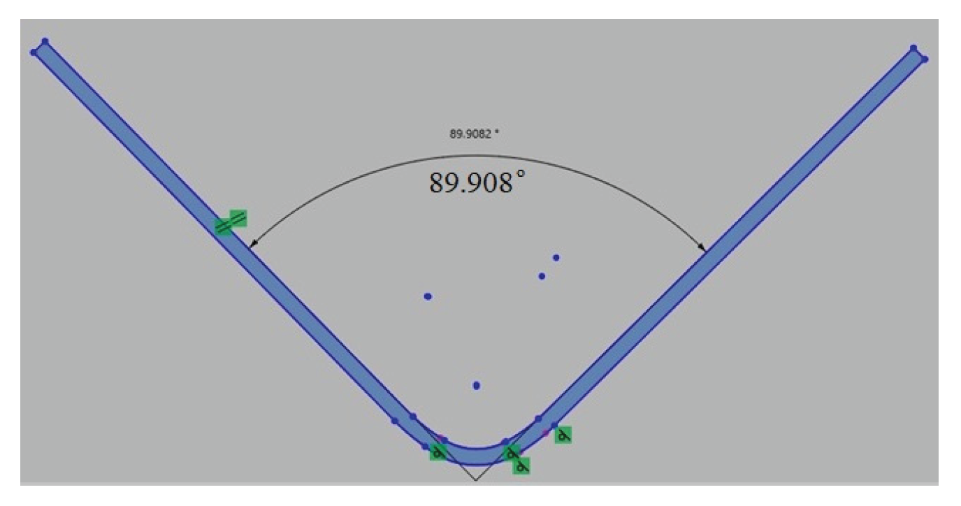
Figure 18.
Measuring the bending angle on a virtual bent part in Geomagic design software.
Figure 18.
Measuring the bending angle on a virtual bent part in Geomagic design software.
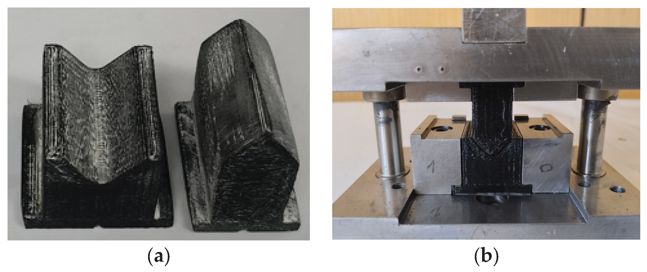
Figure 19.
Additively manufactured ABS tool: (a) punch and die after post-processing; (b) mounted ABS components in the bending tool.
Figure 19.
Additively manufactured ABS tool: (a) punch and die after post-processing; (b) mounted ABS components in the bending tool.
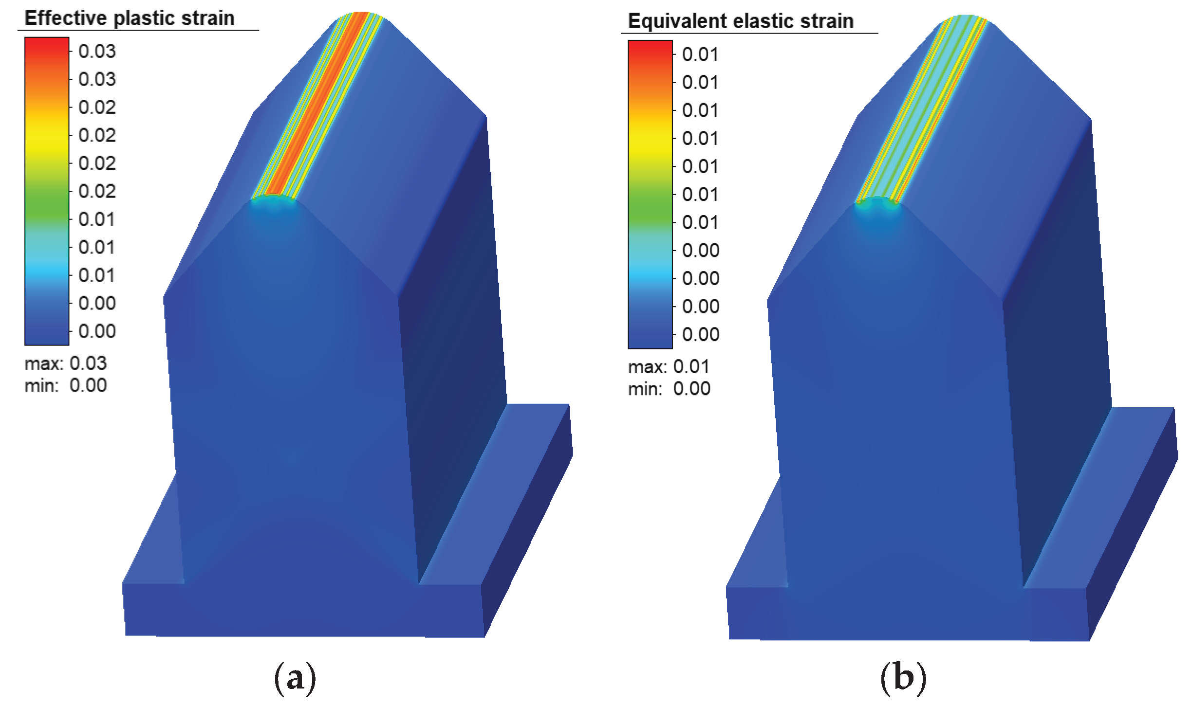
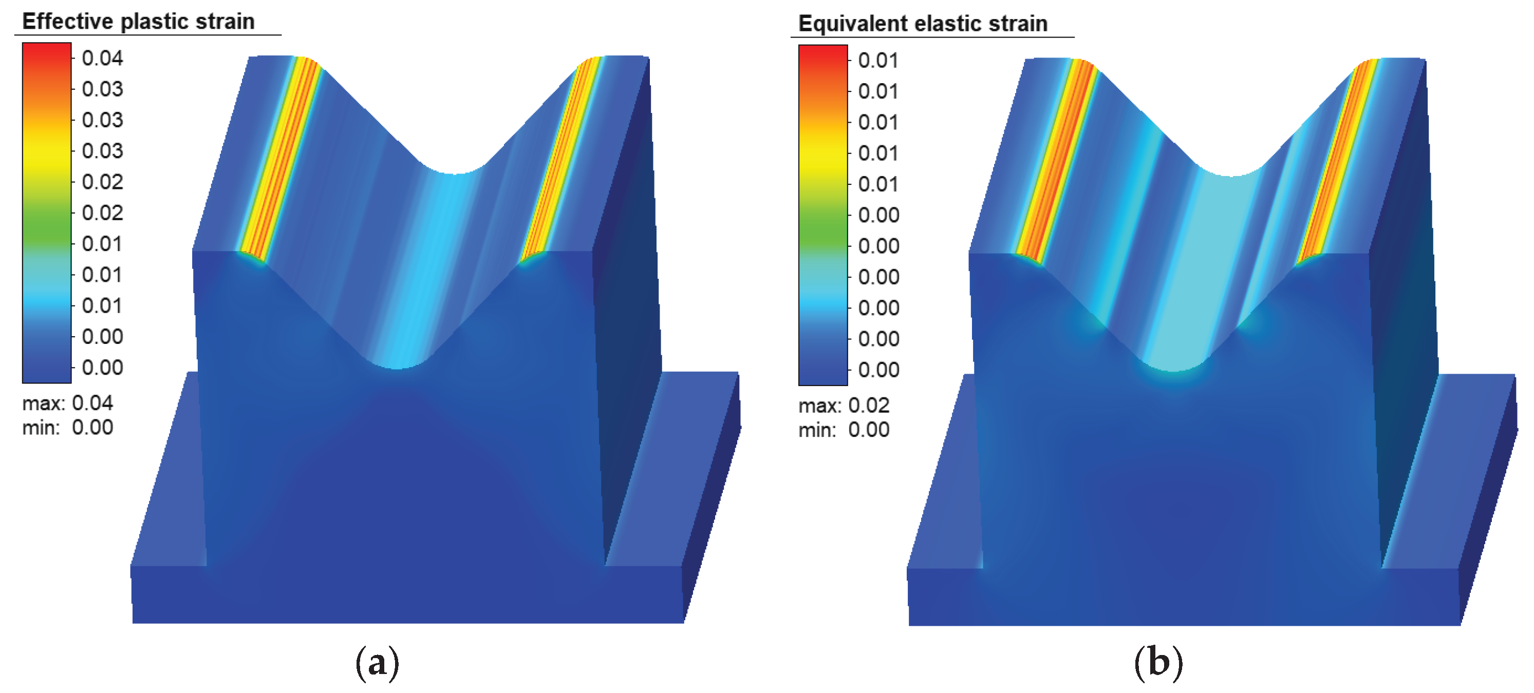
Figure 20.
Distribution of strains on the ABS punch: (a) effective plastic; (b) equivalent elastic.
Figure 20.
Distribution of strains on the ABS punch: (a) effective plastic; (b) equivalent elastic.
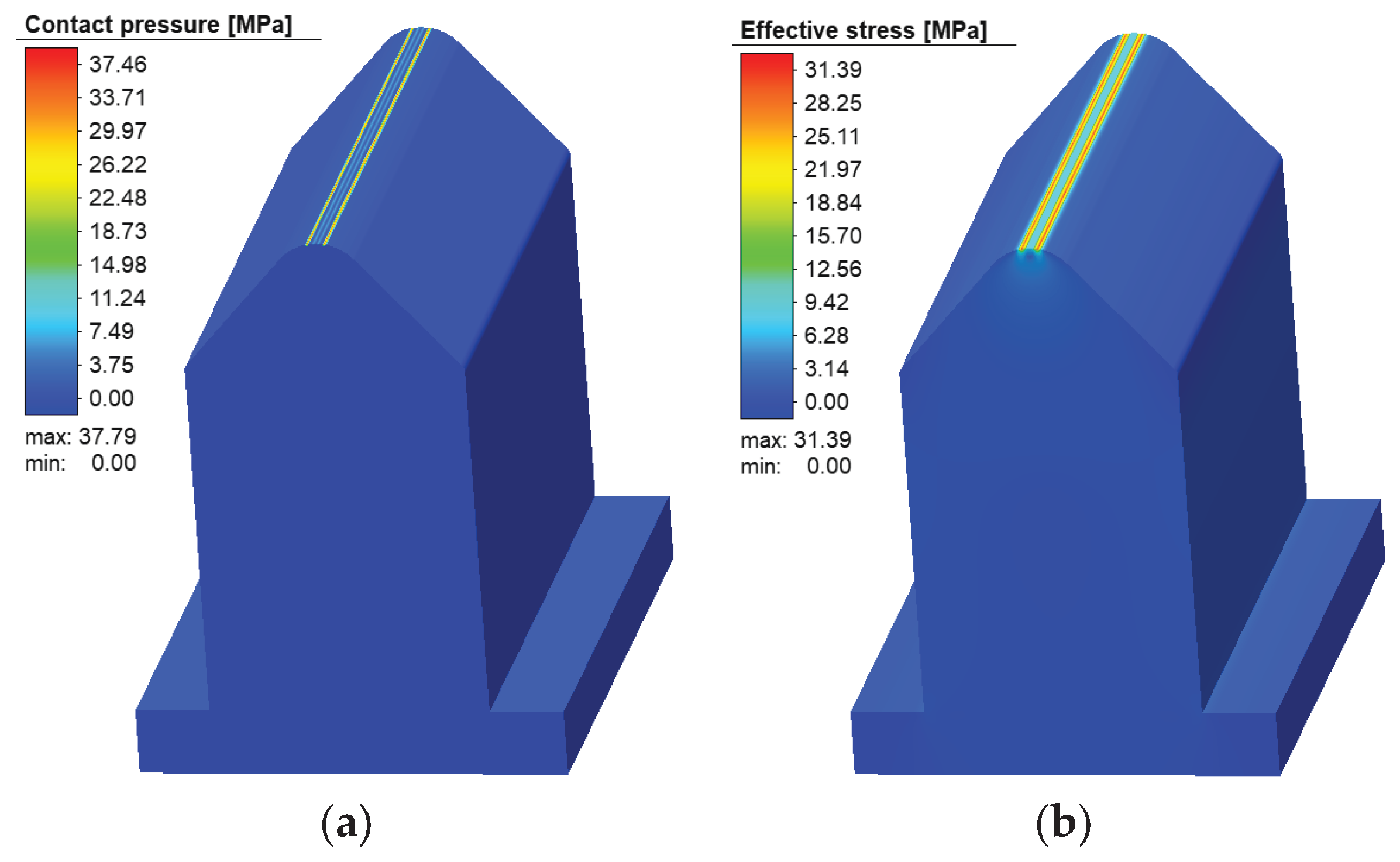
Figure 21.
Distribution of contact pressure (a) and effective stress (b) on the ABS punch.
Figure 21.
Distribution of contact pressure (a) and effective stress (b) on the ABS punch.
Figure 22.
Distribution of strains on the ABS die: (a) effective plastic; (b) equivalent elastic.
Figure 22.
Distribution of strains on the ABS die: (a) effective plastic; (b) equivalent elastic.
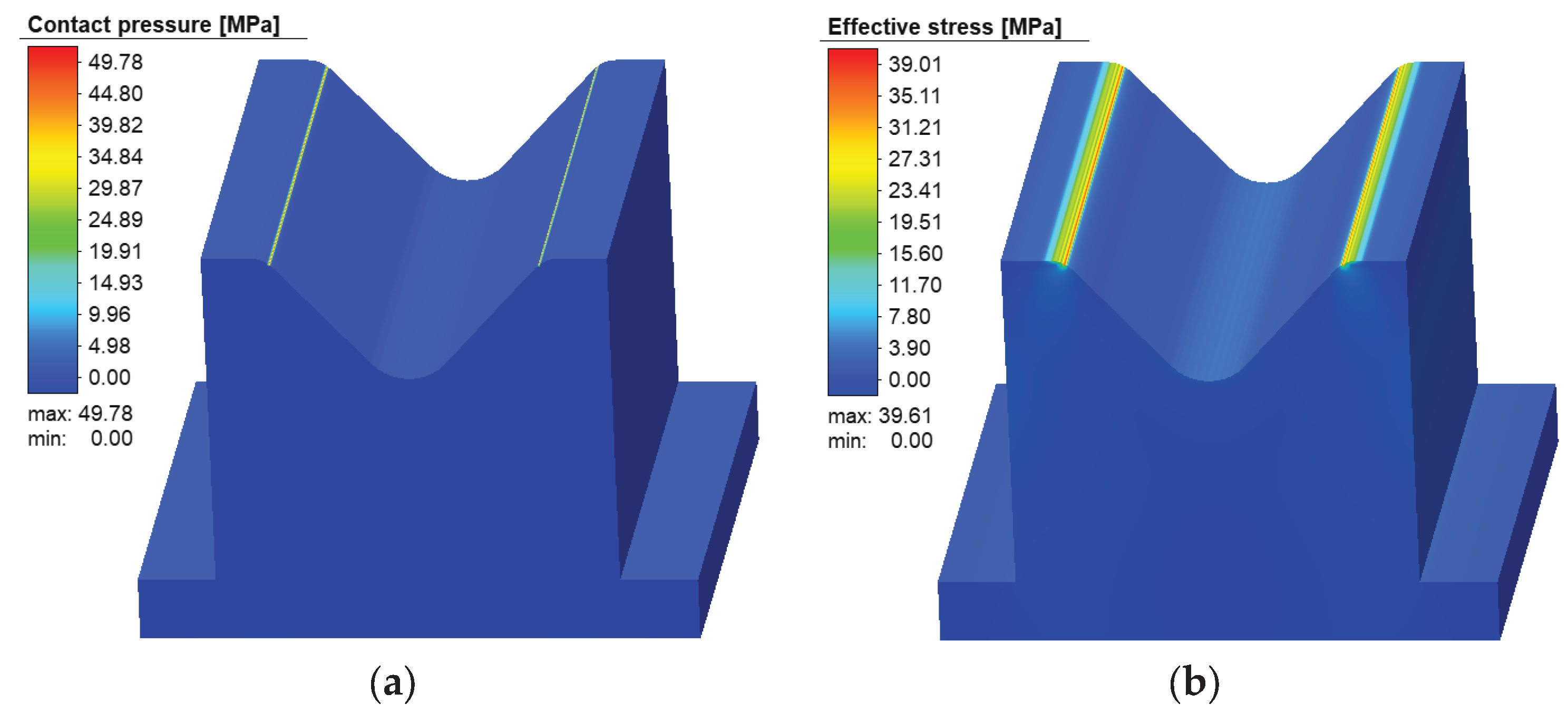
Figure 23.
Distribution of contact pressure (a) and effective stress (b) on the ABS die.
Figure 23.
Distribution of contact pressure (a) and effective stress (b) on the ABS die.
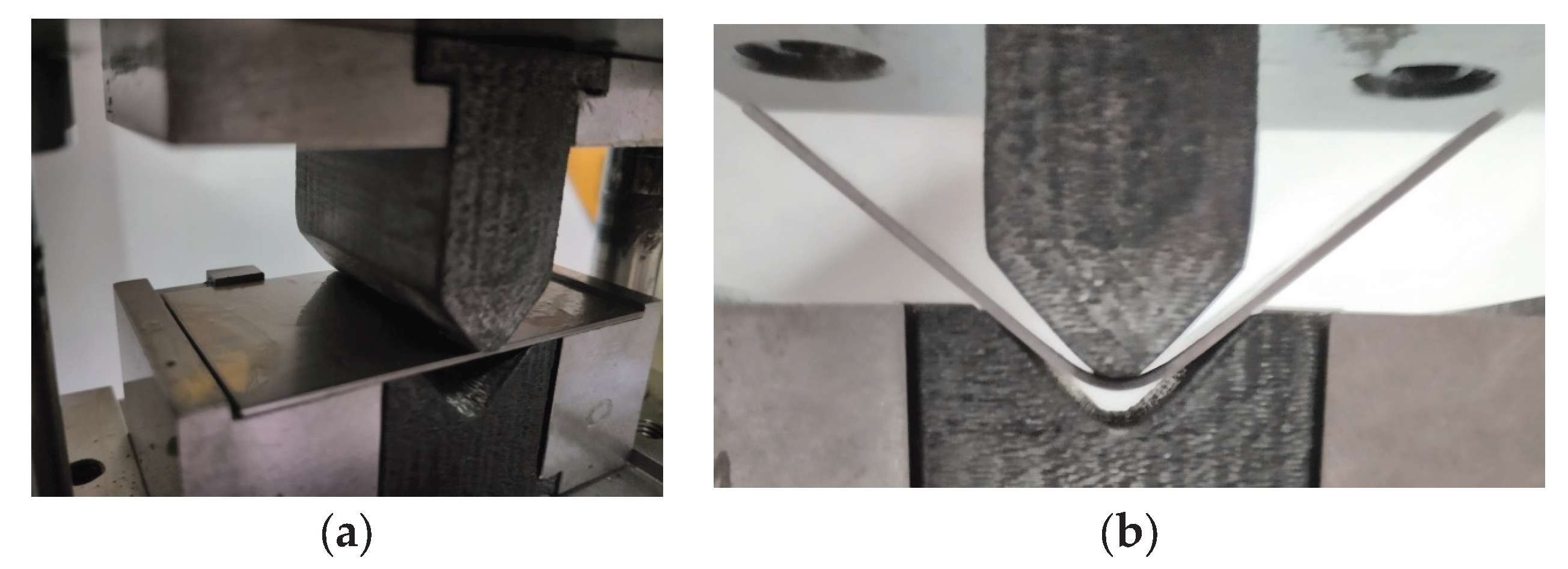
Figure 24.
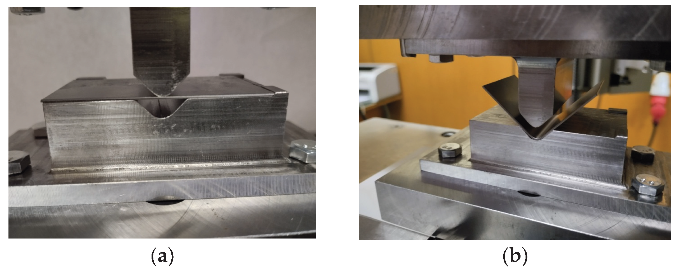
ABS tool mounted on the machine: (a) at the beginning and b) during the air-bending process.
Figure 24.
ABS tool mounted on the machine: (a) at the beginning and b) during the air-bending process.
Figure 25.
Comparison of force–displacement responses for metallic and ABS bending tools.
Figure 25.
Comparison of force–displacement responses for metallic and ABS bending tools.
Table 1.
DC04 mechanical properties.
Table 1.
DC04 mechanical properties.
| Angle |
Rp, MPa |
Rm, MPa |
A120, % |
| 0˚ |
151 |
301 |
40.87 |
| 45˚ |
158 |
311 |
39.06 |
| 90˚ |
153 |
290 |
39.90 |
Table 2.
Experimental plan, tensile strength values and S/N ratios for FDM-printed ABS.
Table 2.
Experimental plan, tensile strength values and S/N ratios for FDM-printed ABS.
| Run |
U |
s |
Rm, MPa |
S/N |
| 1 |
U1(0˚/90˚) |
S1(0.1 mm) |
37.19 |
31.4085 |
| 2 |
U1(0˚/90˚) |
S2(0.2 mm) |
35.64 |
31.0388 |
| 3 |
U1(0˚/90˚) |
S3(0.3 mm) |
35.15 |
30.9185 |
| 4 |
U3(30˚/60˚) |
S1(0.1 mm) |
39.35 |
31.8989 |
| 5 |
U3(30˚/60˚) |
S2(0.2 mm) |
36.78 |
31.3122 |
| 6 |
U3(30˚/60˚) |
S3(0.3 mm) |
38.55 |
31.7205 |
| 7 |
U4(45˚/-45˚) |
S1(0.1 mm) |
40.38 |
32.1233 |
| 8 |
U4(45˚/-45˚) |
S2(0.2 mm) |
38.98 |
31.8168 |
| 9 |
U4(45˚/-45˚) |
S3(0.3 mm) |
38.92 |
31.8035 |
Table 3.
Experimentally measured bending angles.
Table 3.
Experimentally measured bending angles.
| Forming Load (N) |
Bent Angle, (Scanner) |
Bent Angle (Goniometer) |
Difference |
| 600 |
95.89˚ |
96˚ |
0.11˚ |
| 1000 |
93.64˚ |
93.5˚ |
0.14˚ |
| 1500 |
93.18˚ |
93.2˚ |
0.02˚ |
| 2000 |
92.51˚ |
92.5˚ |
0.01˚ |
Table 4.
Comparison of bending angles.
Table 4.
Comparison of bending angles.
| Forming Load (N) |
Bending Angle, (Experiment) |
Bending Angle (Numerical Simulation) |
Difference |
| 600 |
95.89˚ |
96.33° |
0.46% |
| 1000 |
93.64˚ |
94.66° |
1.08% |
| 1500 |
93.18˚ |
94.42° |
1.31% |
| 2000 |
92.51˚ |
93.46° |
1.02% |
Table 5.
Numerical experiment plan for springback compensation.
Table 5.
Numerical experiment plan for springback compensation.
| Numerical Experiment |
Punch and Die Angle Combinations |
Die Angle αm |
Punch Angle αo
|
| 1 |
1.1 |
84° |
83° |
| |
1.2 |
84° |
84° |
| 2 |
2.1 |
85° |
84° |
| |
2.2 |
85° |
85° |
| 3 |
3.1 |
86° |
85° |
| |
3.2 |
86° |
86° |
Table 6.
Numerically estimated bending angles after unloading.
Table 6.
Numerically estimated bending angles after unloading.
| Numerical Experiment |
Punch and Die Angle Combinations |
Numerically Estimated Bending Angles |
Difference from 90° |
| 1 |
1.1 |
88.94° |
1.06° |
| |
1.2 |
88.89° |
1.11° |
| 2 |
2.1 |
89.89° |
0.11° |
| |
2.2 |
89.90° |
0.10° |
| 3 |
3.1 |
90.91° |
0.91° |
| |
3.2 |
90.78° |
0.78° |
Table 7.
Experimental verification of springback compensation.
Table 7.
Experimental verification of springback compensation.
| Experiment |
Measured Bending Angles |
Numerically Estimated Bending Angles |
Difference |
| 1 |
89.83° |
88.90° |
-0.07° |
| 2 |
89.40° |
88.90° |
-0.50° |
| 3 |
89.31° |
89.90° |
-0.59° |
| 4 |
89.39° |
89.90° |
-0.51° |
| 5 |
89.73° |
89.90° |
-0.17° |
| Average |
89.53° |
89.90° |
-0.37° |
Table 8.
Measured bending angles obtained with ABS tools and comparison with metallic tools and numerical predictions.
Table 8.
Measured bending angles obtained with ABS tools and comparison with metallic tools and numerical predictions.
| Exp. |
Bending Angles (ABS Tools) |
Bending Angles (Metallic Tools) |
Difference (ABS vs Metallic) |
Numerically Estimated Angles |
Difference (ABS vs Numerical) |
| 1 |
90.27° |
89.83° |
0.44° |
88.90° |
0.37° |
| 2 |
90.20° |
89.40° |
0.80° |
88.90° |
0.30° |
| 3 |
90.52° |
89.31° |
1.21° |
89.90° |
0.62° |
| 4 |
90.43° |
89.39° |
1.04° |
89.90° |
0.53° |
| 5 |
90.77° |
89.73° |
1.04° |
89.90° |
0.87° |
| Aver. |
90.43° |
89.53° |
0.90° |
89.90° |
0.59° |