
Submitted:
22 December 2025
Posted:
24 December 2025
You are already at the latest version
Abstract
As a solid-state joining technology, friction stir welding (FSW) exhibits significant advantages for aluminium alloys, including low heat input and minimal intermetallic compounds formation, thereby enhancing joint quality and mitigating deformation. This study investigates the single-sided and double-sided FSW processes of 3-mm-thick 7075-T6 aluminium alloy sheets, focusing on characterizing the microstructure and mechanical properties of the joints. Experimental results show that under 1500 rpm rotation speed and 80 mm/min welding speed, the double-sided co-directional FSW joint achieves a tensile strength of 388 MPa and an elongation of 7.09%, significantly outperforming the other two welding paths. In the weld nugget zone (WNZ), continuous dynamic recrystallization (CDRX) occurs, generating uniformly refined equiaxed grains (average size: 1.10 μm) and facilitating the transformation of low-angle grain boundaries (LAGBs) to high-angle grain boundaries (HAGBs). Meanwhile the strong Rotated Cube texture is remarkably weakened into random recrystallized Brass textures with the lowest kernel average misorientation (KAM) value in the WNZ. In contrast, the thermo-mechanically affected zone (TMAZ) accumulates high-density LAGBs due to welding-induced plastic deformation. Microhardness testing reveals a typical "W"-shaped distribution: WNZ hardness is relatively high but slightly lower than that of the base metal (BM), and the minimum hardness in the advancing side (AS) heat-affected zone (HAZ) is higher than that on the retreating side (RS). This study confirms that double-sided co-directional FSW crucially regulates microstructural evolution and improves mechanical properties of 7075-T6 joints, providing a viable process optimization strategy for high-quality welding of thin-gauge sheets.
Keywords:
7075-T6 aluminium alloy
; friction stir welding
; mechanical properties
; microstructural evolution
1. Introduction
Owing to their core properties including low density, high specific strength, and superior heat treatment strengthening capability, 7xxx series high-strength aluminium alloys have been widely adopted in high-end equipment manufacturing fields such as aerospace and rail transit in recent years [1,2,3]. However, these alloys exhibit poor weldability: traditional fusion welding processes tend to induce joint defects such as porosity, hot cracking, alloying element burnout, and large workpiece deformation, severely limiting their application in critical load-bearing structures. In contrast, Friction Stir Welding (FSW), a solid-state joining technology, can effectively circumvent these fusion welding-related defects [4], offering an ideal solution for the reliable joining of 7xxx series aluminium alloys.
Invented by The Welding Institute (TWI) in the UK in 1991, FSW has achieved industrialization and practicality after over three decades of development, demonstrating great potential to replace traditional fusion welding processes in aluminium alloy fabrication [5] Its core welding principle involves: a stir tool rotating at high speed while traversing along the welding direction; through frictional heat generation and mechanical stirring between the tool and workpiece, the workpiece material undergoes plastic flow to achieve metallurgical bonding [6,7]. This solid-state joining inherently prevents aluminium alloy melting, effectively resolving defects that occur during fusion welding of traditionally difficult-to-weld aluminium alloys [8]. Consequently, it exhibits significant technical advantages in welding 7xxx series difficult-to-weld aluminium alloys [9].
In recent years, double-sided friction stir welding (FSW) technology for aluminium alloys has advanced steadily. By optimizing process parameters, selecting appropriate tools, and refining post-treatment processes, joint formation quality and mechanical properties can be effectively enhanced to meet the welding requirements of high-performance aluminium alloy components [10,11]. Compared with single-sided welding, this technology is more suitable for thicker aluminium alloy sheets: welding both sides of the workpiece individually overcomes the limitations of single-pass welding, achieves more uniform heat distribution in the weld zone, and thereby improves the consistency of joint cross-sectional formation. To date, scholars worldwide have conducted extensive research on FSW of medium-thick 7xxx series aluminium alloys, accumulating substantial foundational data:
Yuk S et al. [12] investigated FSW of 12 mm-thick 7075 aluminium alloy sheets. Their results indicated that the Weld Nugget Zone (WNZ) underwent grain refinement via dynamic recrystallization, featuring low dislocation density. In contrast, the Thermo-Mechanically Affected Zones (TMAZ) on both sides of the weld experienced severe plastic deformation under the synergistic effect of mechanical force and thermal cycling, leading to a significant increase in dislocation density and exhibiting distinct microstructural differences between the two sides. Meanwhile, second-phase particles in the Heat-Affected Zone (HAZ) exhibited coarsening behavior.
Canaday et al. [13] examined the mechanical properties of FSW joints in 30 mm-thick AA7050 aluminium alloy, further revealing the non-uniform microhardness distribution along the thickness direction of the joint cross-section: the minimum microhardness at the weld center was significantly lower than that at the top and bottom regions. This phenomenon is strongly associated with uneven heat distribution during welding: the weld center undergoes higher heat input, resulting in a more pronounced material softening effect, whereas the top and bottom regions dissipate heat more rapidly, leading to relatively milder softening.
Reza-E-Rabby Md et al. [14] performed high-speed FSW butt welding experiments on 25.4 mm-thick AA7175-T79 aluminium alloy. The results showed that double-sided FSW joints exhibited significant grain refinement and high local strain. Compared with low-speed single-sided FSW, their yield strength was enhanced by 20%-24%, and tensile strength reached approximately 76% of the base material’s.
Youlia RP et al. [15] demonstrated that for thicker aluminium alloy sheets, single-sided FSW fails to ensure full-thickness joint formation quality, whereas Co-directional Double-sided FSW (CDS-FSW) achieves more uniform heat transfer and effectively reduces welding defects by welding both sides of the workpiece separately. Tang Y et al. [16] conducted CDS-FSW experiments on 6061 aluminium alloy, showing that although this process requires two welding passes, it can reduce single-pass welding difficulty in certain scenarios, thereby improving overall welding efficiency. Hendrato H et al. [17] studied CDS-FSW performance of AA6061-T6 aluminium alloy and found that this process can regulate grain size and phase distribution in the weld zone, thereby enhancing the joint’s overall performance. Dwivedi VK et al. [18] compared single-sided and double-sided FSW of AA6062 aluminium alloy, revealing that double-sided welding significantly improves weld mechanical properties through grain refinement and strain hardening effects, while reducing defects such as porosity and internal stress, and enhancing joint fatigue strength and overall welding quality.
7075-T6 aluminium alloy serves as the core material in aerospace thin-walled load-bearing structures (e.g., aircraft fuselage skins and wing ribs). The microstructure and mechanical properties of its welded joints directly determine component service safety and service life. However, existing research primarily focuses on FSW of medium-thick 7xxx series aluminium alloys, and research on 3-mm-thick 7075-T6 sheets remains limited. In particular, regarding the interface regulation mechanism and performance correlation of CDS-FSW joints, no systematic research findings have been established, which cannot meet the requirements for refined welding processes and high joint reliability in aerospace thin-walled structures. Based on this, this study focuses on 3 mm-thick 7075-T6 sheets, conducting FSW butt welding experiments using three welding paths. By analyzing the macroscopic morphology, microstructure, microhardness distribution, tensile properties, and fracture morphology of joints under optimal process parameters, combined with crystallographic characteristics of each region (e.g., grain size, grain boundary proportion, kernel average misorientation, and texture evolution), the regulation mechanism of CDS-FSW on the interface microstructure of 7075-T6 thin-sheet welded joints and its influence on mechanical properties are systematically explored, laying a theoretical and experimental foundation for optimizing the welding process of this material in thin-walled structures.
2. Materials and Methods
2.1. Friction Stir Welding (FSW)
The material employed in this experiment was 7075-T6 aluminium alloy sheets with dimensions of 100 mm × 50 mm × 3 mm, and their main chemical composition is presented in Table 1.
The experiment was performed using a dedicated FSW machine (Model: FSW-RT31-003), as illustrated in Figure 1. The stir tool comprised a shoulder and a stir pin: the shoulder had a diameter of 10 mm, while the stir pin adopted a threaded conical-cylindrical design with a diameter of 5 mm and a length of 2.5 mm. Before welding, the angle between the central axis of the stir tool and the machine's main spindle axis was calibrated to 0°. Detailed welding parameters employed in this study were summarized in Table 2. Three distinct welding approaches were adopted in the experiments, namely single-sided friction stir welding (SS-FSW), double-sided co-directional friction stir welding (DS-CD-FSW), and double-sided counter-directional friction stir welding (DS-CtD-FSW). For the double-sided FSW (DS-FSW) tests, the welding procedure was conducted in two sequential steps: initially, the front side of the specimens was welded; subsequent weld flash removal was performed to ensure surface flatness and smoothness. Subsequently, the specimens were flipped over, and a second weld was executed at the identical starting position of the first weld to produce DS-FSW joints. Specifically, DS-CD-FSW was defined as the configuration in which the welding direction of the second pass was consistent with that of the first pass, while DS-CtD-FSW was defined as the case where the two passes were welded in opposite directions. Schematic illustrations of the welding processes corresponding to the three approaches were presented in Figure 2.
2.2. Microstructure Characterization
Subsequent to the welding experiments, metallographic specimens were harvested from the weld regions, and the sampling configuration is illustrated in Figure 3(c). Following grinding and mechanical polishing, the specimens were etched via Keller's reagent (1 vol.% HF + 1.5 vol.% HCl + 2.5 vol.% HNO₃ + 95 vol.% H₂O), then promptly rinsed with absolute ethanol and air-dried using a forced-air blower. The microstructural characteristics of each joint region were examined via an Olympus GX53 metallographic microscope. Crystallographic data of the welded joints were acquired utilizing the electron backscatter diffraction (EBSD) system integrated with a FEI Verios 460 field-emission scanning electron microscope (FE-SEM), and the collected data were post-processed using TSL OIM Analysis software.
Room-temperature X-ray diffraction (XRD) measurements were performed utilizing a DX-2700BH X-ray diffractometer. Prior to measurements, the specimen surfaces were polished to a mirror finish using 1200-grit sandpaper. The diffractometer featured a maximum power output of 3 kW, with its stability maintained within ±0.03%. The step increment was set to 0.02°, with a dwell time of 0.6 s per step. Cu Kα radiation (λ = 0.15405 nm) was employed as the X-ray source, with a diffraction angle range of 10° to 100° and a scanning rate of 5°/min.
2.3. Mechanical Testing
Micro-Vickers hardness measurements of the welded joints were performed on the weld cross-section using a HVS-1000 microhardness tester. The applied load was set to 0.2 kgf, with a dwell time of 15 s. Measurements were initiated from the base metal on one side, proceeding along the weld centerline at an interval of 0.2 mm between adjacent indentations, until reaching the opposite base metal. The schematic of indentation distribution for the joint microhardness test is illustrated in Figure 3(a).
In accordance with the national standard GB/T228.1-2021 Metal Materials - Tensile Testing, standard tensile specimens were fabricated from the base metal and welded joints via wire electrical discharge machining (WEDM), with the sampling direction perpendicular to the welding direction. The dimensions of the tensile specimens and the sampling configuration are depicted in Figure 3(b) and (c). The surfaces of the tensile specimens were ground to a smooth finish using sandpaper. Room-temperature tensile tests were performed on a universal testing machine (model: WDW-100C) at a crosshead speed of 1 mm/min. To ensure the reliability and reproducibility of the test results, three replicate specimens were tested for each set of welding parameters, with the average value adopted as the final result. Subsequently, the fracture morphology of the welded joints was characterized via scanning electron microscopy (SEM), and the secondary phase particles (gold-rich) in the fracture regions were analyzed using energy-dispersive X-ray spectroscopy (EDS).
3. Results and Discussion
3.1. Macroscopic Morphology Analysis
Figure 4 and Figure 5 illustrate the macroscopic appearance and cross-sectional morphology of friction stir welding welds of 7075-T6 aluminium alloy thin sheets under three distinct welding paths, respectively.
Evident from Figure 4, the weld surfaces exhibit a smooth finish with dense and well-ordered fish-scale patterns across all three welding paths, free of grooves or furrows. Nevertheless, minor flash defects were observed in all cases. Compared with that on the retreating side (RS) of DS-FSW welds, the flash on the RS of SS-FSW welds is more pronounced. This phenomenon is presumably ascribed to the higher downward pressure applied during the SS-FSW process (to ensure full backside penetration in SS-FSW, the weld width is approximately 3 mm, as depicted in Figure 4(a)). The increased downward pressure expands the contact area between the tool shoulder and the workpiece surface, which in turn generates elevated frictional heat and greater axial force. Consequently, the extrusion effect on the material in the weld zone is enhanced, leading to increased extrusion of softened material from the weld region.
As shown in Figure 5, the cross-sections of the two DS-FSW joint types display distinct hourglass-shaped characteristics, which are significantly different from the basin-shaped cross-section of the SS-FSW joint. The weld widths under the three welding paths are essentially consistent, whereas the weld height in SS-FSW is lower than that in DS-FSW. For DS-FSW joints, an overlapping zone is formed in the central part of the weld, resulting from the superposition effect of the two welding passes (i.e., front and back sides). In dual-sided counter-directional FSW (DS-CtD-FSW) joints, the microstructures on the advancing side (AS) and RS of the first weld pass, as well as those of the second weld pass, are symmetrically distributed along the cross-sectional centerline, as presented in Figure 5(c). In contrast, the microstructures on the AS and RS of both the first and second weld passes in dual-sided co-directional FSW (DS-CD-FSW) joints exhibit asymmetric distribution along the centerline, as illustrated in Figure 5(b).
Notably, obvious tunnel void defects were detected inside the DS-CtD-FSW joints (Figure 5(c)), which is likely caused by insufficient metal filling in local regions during the welding process. In comparison with the DS-CD-FSW joints (Figure 5(b)), only a small number of finely dispersed micropores are present in the weld nugget zone (WNZ). This indicates that the variation in welding direction exerts a significant influence on the formation of internal weld defects. When the welding parameters are improperly matched, the metal extrusion rate inside the joint exceeds the metal filling rate, resulting in local negative pressure that ultimately induces the formation of tunnel void defects.
3.2. Microstructural Analysis
During the FSW process, the base metal (BM), heat-affected zone (HAZ), thermo-mechanically affected zone (TMAZ), and weld nugget zone (WNZ) are located at different distances from the weld center. These zones experience significantly different degrees of deformation and thermal cycles, which in turn induce distinct positional variations in microstructure.
Figure 6 presents the microstructures of different zones in 7075-T6 aluminium alloy FSW joints fabricated via the three welding paths. Comparison of the metallographic micrographs of each zone across the three welding paths reveals that welding paths exert a notable influence on both the grain refinement effect and deformation characteristics of the microstructure in each zone. The BM exhibits a lath-like structure aligned along the rolling direction, with grains predominantly forming a uniformly distributed banded structure. The grain boundaries are well-defined, without obvious deformation or recrystallization features, as illustrated in Figure 6(a, e, i). Under all three welding paths, the BM retains its banded structure along the rolling direction, with no significant deformation or recrystallization observed. This indicates that the welding heat input has not exerted a substantial impact on the original microstructure of the BM.
The HAZ is adjacent to the BM and relatively distant from the stir tool. During welding, this zone undergoes no significant plastic deformation; however, thermal cycling effects induce a slight grain growth tendency compared to the BM [19], as shown in Figure 6(b, f, j). The grain growth behaviour in the HAZ is closely associated with the heat input distribution of the welding path. For DS-FSW joints, the microstructure is subjected to dual heat inputs, resulting in a slightly larger grain size than that in SS-FSW joints. Furthermore, the degree of grain growth in DS-CD-FSW joints is lower than that in DS-CtD-FSW joints. This suggests that heat diffusion is more uniform in DS-CD-FSW, which effectively inhibits grain coarsening.
The TMAZ is synergistically influenced by the mechanical shear action of the stir tool and welding heat input. Compared to the WNZ, the shear action in the TMAZ is weaker, leading to insufficient deformation to induce complete grain recrystallization. Driven by the rotation of the stir tool, grains in this zone undergo partial deformation. Additionally, the deformation degree of the TMAZ varies significantly with the welding path. Figure 6(c, g, k) display the microstructures of the AS-TMAZ under the three welding paths. For DS-FSW joints, grain distortion is more severe, with obvious grain boundary bending induced by shear action; some grains are elongated along the stirring direction to form a fibrous structure. In contrast, for SS-FSW joints, the TMAZ is only subjected to stirring action on one side, resulting in inadequate shear force transmission and the minimum degree of grain deformation. Moreover, this zone retains the lath-like characteristics of numerous original grains.
The WNZ is in direct contact with the stir tool. Under the combined effects of thermal action and shear force, the original fibrous grains undergo rapid plastic deformation accompanied by dynamic recrystallization, ultimately transforming into fine equiaxed grains [20], as presented in Figure 6(d, h, l). The two DS-FSW processes exhibit more significant grain refinement effects and more uniform grain distribution compared to SS-FSW. This is attributed to the fact that the rotating stir tool applies shear force twice on the upper and lower surfaces of the workpiece, leading to more intense plastic deformation and dynamic recrystallization of the material [21]. Obvious black particles are observed in the WNZ of SS-FSW joints, which are presumably incompletely fragmented second-phase particles. In contrast to DS-FSW joints, the stir tool only exerts shear action on the upper surface of the workpiece during SS-FSW, resulting in weaker plastic deformation of the material and inadequate refinement and dispersion of second-phase particles. Consequently, more large-sized black particles are retained in the WNZ. No obvious dynamically recrystallized grain refinement zone is formed around these incompletely fragmented second-phase particles, indicating their weak hindering effect on grain boundary migration. This is also one of the reasons why the grain refinement effect in the WNZ of SS-FSW joints is inferior to that of DS-FSW joints.
Comparison of the microstructures across different zones reveals a gradient variation in grain morphology from the BM to the WNZ: transitioning from a banded structure to partial deformation, and ultimately to fine equiaxed grains. This variation directly reflects the differences in thermo-mechanical coupling effects imposed on each zone during the FSW process.
Electron backscatter diffraction (EBSD) analysis was conducted to investigate the evolution characteristics of the microstructure in each zone of DS-CD-FSW 7075-T6 aluminium alloy thin sheets in depth, including grain size, grain boundary characteristics, texture, and orientation distribution, among other key aspects.
Figure 7 presents the inverse pole figures (IPF) and grain size distribution histograms of each zone in the joint. Evident from the figures is that the BM exhibits lath-shaped grains with long axes aligned parallel to the rolling direction, featuring an average grain size of 24.05 μm and a relatively high proportion of grains around 20 μm. Compared to the BM, the HAZ exhibits no significant change in grain morphology, with an average grain size of 24.68 μm and a predominant proportion of grains around 24 μm. This is attributed to the thermal effect experienced by the HAZ during welding, resulting in a marginal increase in grain size relative to the BM.
The TMAZ grains display distinct deformation features, characterized by significant plastic deformation, grain elongation or fragmentation, and curved, irregular grain boundaries. The TMAZ has an average grain size of 8.43 μm and an uneven grain size distribution, with relatively high proportions of grains around 2 μm, around 13 μm, and larger than 20 μm. In contrast, the WNZ is fully transformed into fine equiaxed grains, exhibiting a substantial reduction in grain size and well-defined, uniformly distributed grain boundaries. This is primarily attributed to the fact that the WNZ undergoes continuous dynamic recrystallization (CDRX) under the synergistic effects of intense mechanical stirring by the stir tool and frictional heating. The original lath-shaped grains in the BM are thoroughly refined and reconstructed, resulting in an average grain size of merely 1.10 μm and a relatively concentrated grain size distribution.
Figure 8 depicts the grain boundary (GB) maps and grain orientation difference distribution histograms of each zone in the joint. The GB maps illustrate the distribution of grain boundaries, categorized into low-angle grain boundaries (LAGBs, 2°–15°, denoted by red lines) and high-angle grain boundaries (HAGBs, >15°, denoted by blue lines). The BM exhibits a high HAGB fraction of 94.3%, while the LAGB and HAGB fractions in the HAZ are comparable to those in the BM.
Notably, the TMAZ exhibits a substantial increase in LAGB density. This is because the TMAZ undergoes intense mechanical stirring during FSW, inducing severe plastic deformation of grains and a sharp increase in dislocation density [22]. Concurrently, the welding thermal cycle experienced by the TMAZ facilitates the migration and recombination of partial dislocations, further promoting LAGB formation. Consequently, the LAGB fraction in the TMAZ is significantly higher than that in the BM and HAZ. In contrast, the WNZ undergoes dynamic recrystallization, which converts a significant number of LAGBs into HAGBs [23].
Figure 9 presents the grain orientation spread (GOS) maps of each zone in the 7075-T6 aluminium alloy DS-CD-FSW joint. GOS is widely employed to characterize the recrystallization fraction of materials. Typically, recrystallized grains exhibit low GOS values (0–2°), recovered grains display medium GOS values (2°–7°), and deformed grains show high GOS values (>7°) [24].
As evidenced by the figure, the base metal (BM) displays a relatively homogeneous grain orientation, with the majority of grain orientation spread (GOS) values distributed within the low range. This indicates that the BM is predominantly composed of recrystallized grains, consistent with the absence of complex stress and thermal effects on this zone during welding. Compared to the BM, the HAZ exhibits a moderate increase in GOS values, with partial formation of recovered grains. This is presumably attributed to the welding thermal cycle, which induces a certain degree of dislocation migration and recombination within the grains.
The TMAZ exhibits a wide distribution of GOS values, with recrystallized grains accounting for 34.5% and deformed grains for 17.7%. This is because the TMAZ is simultaneously subjected to mechanical stirring by the stir tool and welding thermal cycling during the process. Mechanical stirring induces severe plastic deformation of grains in this zone, leading to grain fragmentation and orientation variation, thereby generating a certain proportion of deformed grains. Meanwhile, the welding thermal cycle provides energy for grain recovery and recrystallization, facilitating dislocation migration and recombination within grains and forming a certain number of recrystallized grains. Such a complex stress-thermal environment results in diverse grain states in the TMAZ.
In contrast, the WNZ generally exhibits low GOS values, dominated by recrystallized grains. During welding, the WNZ is located at the center of intense stir tool action, where grains are fully fragmented and mixed. The formation of recrystallized grains renders the grain orientation in the WNZ relatively uniform. Compared to other zones, the WNZ exhibits a higher recrystallization degree, with finer and more uniform grains. This uniform, fine recrystallized grain structure exerts a significant influence on the mechanical properties of the WNZ.
Figure 10 presents the kernel average misorientation (KAM) maps of each zone in the joint. Quantitative analysis of KAM values enables further confirmation of the plastic deformation degree and internal stress distribution characteristics across different zones. Evident from the maps are significant differences in KAM value distribution among various zones.
Notably, the BM exhibits generally low KAM values, indicating minimal lattice distortion within the grains. This is attributed to the fact that the BM is not subjected to welding thermal cycling or mechanical loading. The HAZ exhibits slightly higher KAM values than the BM, attributed to the influence of welding heat input, which induces a moderate degree of plastic deformation and dislocation accumulation within the grains. However, the deformation degree here is relatively mild compared to that of the TMAZ.
The TMAZ exhibits significantly higher KAM values than other zones, primarily due to intense mechanical stirring and shearing effects during FSW. These effects induce severe plastic deformation of grains, a substantial increase in dislocation density, and a sharp intensification of lattice distortion [25]. In contrast, the WNZ exhibits the lowest KAM values, as dynamic recrystallization during welding results in a relatively moderate intragranular stress state [26,27].
Pole figures (PF) and orientation distribution function (ODF) maps enable comprehensive characterization of the texture characteristics of materials, facilitating the identification of primary texture components and texture intensities across various zones. Figure 11 presents the PF and ODF maps of the BM, HAZ, TMAZ, and WNZ.
As illustrated in Figure 11(a), PF analysis of the 7075-T6 aluminium alloy BM reveals a basal texture with a maximum intensity of 4.791. For the (100) crystal plane orientation, distinct intensity peaks are observed parallel to the normal direction (ND) and at the 45° angle between the rolling direction (RD) and transverse direction (TD), which are characteristic of the rotated cube texture. Evident from the BM's ODF map is a texture density of 8.742, with the BM predominantly composed of the (100)[110] rotated cube texture, accompanied by weaker (110)[111] and cube textures.
For the HAZ (Figure 11(b)), PF analysis indicates a basal texture with a maximum intensity of 5.305. In the (100) crystal plane orientation, a prominent intensity peak is detected parallel to ND; in the (110) crystal plane orientation, an intensity peak appears at the 45° angle between RD and TD, suggesting the dominant presence of the cube texture. The HAZ's ODF map shows a texture density of 6.879, mainly consisting of relatively strong (100)[021] 25° rotated cube texture and cube texture, along with weaker (110)[111] and (221)[110] textures. As the HAZ is primarily affected by welding thermal cycles, its texture exhibits similarity to the as-received processing texture of the base metal.
Regarding the TMAZ (Figure 11(c)), PF analysis yields a basal texture with a maximum intensity of 2.051, which is significantly lower than those of the BM and HAZ. For the (100) crystal plane orientation, a distinct intensity peak is observed at the 45° angle between RD and TD (a signature of the rotated cube texture); for the (110) crystal plane orientation, a prominent intensity peak appears parallel to TD. This phenomenon is attributed to the synergistic effects of mechanical shear from the stir tool and welding thermal cycles during FSW: shear stress along TD facilitates grain plastic deformation, thereby inducing the formation of the intensity peak in this direction.The TMAZ's ODF map reveals a texture density of 4.121, lower than those of the BM and HAZ. This is because partial recrystallization induced by thermal effects has reduced the overall texture density, with the TMAZ characterized by relatively strong (012)[821], (015)[351], and (114)[211] textures, as well as a weaker (001)[310] texture. The underlying mechanism involves a certain degree of plastic deformation in the TMAZ, which causes grain elongation and the formation of deformation textures; concurrently, shear force induces the generation of shear textures. In the case of the WNZ (Figure 11(d)), PF analysis shows a basal texture with a maximum intensity of 1.841, the lowest among all zones. For the (100) crystal plane orientation, a distinct intensity peak is detected at the 30° angle between RD and TD, a characteristic feature of the brass texture. The WNZ's ODF map exhibits a texture density of 2.311, consisting predominantly of numerous brass recrystallization textures (e.g., (223)[122], (014)[541], and (111)[110] BrassR) and a small amount of (100)[110] rotated cube texture.
In the WNZ, severe plastic deformation and elevated temperatures promote grain dynamic recrystallization. The orientations of these newly formed grains differ from those of the original grains, thereby altering the overall texture of the WNZ. During dynamic recrystallization, continuous grain nucleation and growth occur; furthermore, enhanced atomic diffusion under high-temperature conditions imparts a certain degree of randomness to the orientations of the newly formed grains, which effectively weakens the intensity of the original texture [28]. Meanwhile, the welding stress field influences the growth direction of recrystallized grains: some grains preferentially grow along directions favorable to the applied stress, resulting in a more complex texture composition in the WNZ. This zone contains both weak textures formed by random orientations and specific orientation textures generated by stress-induced growth. Such texture variations directly affect the mechanical properties of the WNZ.
3.3. XRD Analysis
The thermal cycles associated with FSW modulate the composition and distribution of precipitated phases in the WNZ [29]. The X-ray diffraction (XRD) patterns are presented in Figure 12. The BM exhibits distinct characteristic peaks of MgZn₂ (η' phase) at 2θ = 38.5°, 44.7°, and 65.1°, as well as characteristic peaks of Al₂CuMg (S phase) at 2θ = 19.2°, 44.5°, and 66.1°. This indicates that nanoscale η and S strengthening phases, precipitated during T6 aging treatment, are uniformly distributed in the BM.
In the XRD spectrum of the WNZ, the intensity of the principal peak corresponding to the η' phase is diminished, with a broadened diffraction peak of MgZn₂ (η phase) appearing at 2θ = 36.8°. This phenomenon indicates that the elevated temperature during welding induces partial dissolution of the η' phase and its coarsening into the equilibrium η phase. Compared with the BM, the content of precipitated phases in the WNZ is reduced; for instance, no trace of the Al₂CuMg (S phase) characteristic peak is detected at 2θ = 19.2° in the WNZ. This is attributed to the fact that the WNZ undergoes severe plastic deformation and dynamic recrystallization during FSW. Concurrently, the welding heat input facilitates the dissolution of a portion of the S phase, rendering it undetectable in the XRD pattern [30].
3.4. Microhardness Analysis
Microhardness distribution of FSW joints is influenced by multiple factors, including grain size, dislocation density, and precipitated phase characteristics [31]. Consistent with the Hall-Petch equation [32], microhardness of the joints exhibits a strong correlation with grain size.
Figure 13 presents the microhardness distribution maps of the cross-sections of 7075-T6 aluminium alloy thin sheet FSW joints. The microhardness distributions under the three welding processes all exhibit a typical "W"-shaped profile: the BM possesses the highest microhardness, the WNZ has a microhardness of approximately 140 HV, the HAZ exhibits relatively low microhardness, and the TMAZ has a microhardness intermediate between that of the WNZ and HAZ.
This hardness variation pattern is primarily attributed to the fact that the strengthening mechanism of 7075 aluminium alloy is dominated by precipitation strengthening [33]. The T6-treated base metal, in its peak aging state (characterized by fine η' strengthening phases and high dislocation density), confers optimal mechanical strength. For the WNZ, severe plastic deformation induces dynamic recrystallization, resulting in the formation of fine recrystallized grains. However, welding heat input elevates the temperature in the WNZ, triggering partial dissolution of precipitated phases [34]. Such dissolution impairs the precipitation strengthening effect of the alloy. Furthermore, residual stresses generated during welding exert a certain influence on joint hardness [35]: residual stresses reduce the effective load-bearing capacity of the material, thereby decreasing its hardness. Consequently, the WNZ exhibits relatively high hardness but lower than that of the as-received BM.
The HAZ is solely subjected to thermal cycles without mechanical deformation, leading to partial dissolution or coarsening of precipitated phases. This not only weakens precipitation strengthening but also induces grain growth, ultimately resulting in relatively low hardness. The TMAZ undergoes thermo-mechanical coupling effects, accompanied by partial dynamic recrystallization, hence its hardness lies between that of the WNZ and HAZ.
To investigate hardness differences between the AS and RS, test points were selected above the weld centerline during microhardness measurements of DS-CD-FSW joints, leading to observed differences in the minimum hardness values of the HAZ between the AS and RS [36]. Across all three welding processes, the minimum hardness of the HAZ adjacent to the AS is higher than that adjacent to the RS. This phenomenon is presumably associated with differences in mechanical effects and thermal cycles experienced by the AS and RS during welding.
As the region where the stir pin rotation direction is consistent with the welding travel direction, the AS undergoes a more intense mechanical stirring effect, leading to enhanced plastic deformation and dynamic recrystallization of the material. Meanwhile, although heat input is relatively concentrated, intense stirring facilitates rapid heat dissipation, resulting in a milder thermal cycle in the AS-HAZ. This mitigates excessive dissolution or coarsening of precipitated phases. In contrast, the RS experiences relatively weaker stirring, leading to a lower degree of plastic deformation; additionally, heat dissipation is less efficient in this region, resulting in a more intense thermal cycle in the RS-HAZ. This induces dissolution or coarsening of precipitated phases as well as grain coarsening, ultimately leading to lower hardness of the RS-HAZ compared to the AS-HAZ [37].
It is also evident from the figure that the HAZ hardness in SS-FSW is slightly higher than that in the two DS-FSW processes. This is presumably because during SS-FSW, the stir pin exerts a single intense mechanical stirring and thermal effect on the weldment from one side. As a result, heat input is more concentrated with a relatively short duration of action, such that strengthening phases in the HAZ do not undergo significant dissolution or coarsening. In contrast, during DS-FSW, both sides of the material are affected by the stir pin, resulting in higher total heat input. Moreover, the superposition of thermal cycles induced by the two stirring processes promotes more sufficient dissolution of strengthening phases in the HAZ. Additionally, prolonged heating duration induces slight grain growth, ultimately leading to marginally lower hardness compared to SS-FSW.
3.5. Tensile Properties
The mechanical properties of aluminium alloy friction stir welded joints are synergistically influenced by multiple factors, including welding heat input, the type, content, morphology, and distribution characteristics of strengthening phases, as well as the presence of welding defects.
Figure 14(a) presents the stress-strain curves of joints fabricated via the three welding processes, where the curves essentially overlap in the elastic deformation stage across different welding methods. Upon entering the plastic deformation stage, discrepancies emerge among the curves. Notably, the joint fabricated by DS-CD-FSW exhibits an extended plateau and higher strain values in the uniform plastic deformation stage, indicating its capacity to sustain greater deformation during plastic deformation. This is presumably attributed to the finer grain structure and more dispersed distribution of strengthening phases achieved by this welding method. These microstructural features enable the material to coordinate deformation through mechanisms such as dislocation motion and grain boundary sliding under stress, thereby delaying the onset of necking.
As illustrated in Figure 14(b), the 7075-T6 aluminium alloy joints fabricated by DS-CD-FSW exhibit optimal comprehensive mechanical properties: the tensile strength reaches 388 MPa (approximately 74.7% of the base metal (BM)), and the fracture elongation is 7.09% (approximately 70.2% of the BM). The tensile properties of DS-CD-FSW joints are significantly superior to those of DS-CtD-FSW joints. This is because DS-CD-FSW yields a denser weld zone structure and more pronounced grain refinement effect.
In contrast, tunnel void defects in DS-CtD-FSW joints significantly deteriorate their tensile properties. Furthermore, DS-CD-FSW more effectively preserves the uniform distribution of strengthening phases, avoiding performance degradation induced by inconsistent welding directions, thereby producing joints with enhanced mechanical performance.
3.6. Fracture Analysis
The tensile fracture positions of the welded joints are primarily concentrated in the TMAZ and HAZ. The fundamental cause is the microstructural inhomogeneity induced by welding thermal cycles [38]. During tensile loading, significant stress concentration occurs in these regions, initiating crack propagation and ultimately leading to fracture failure.
Figure 15 displays the SEM micrographs of tensile fracture surfaces of joints fabricated via the three welding paths. Obvious tear ridges and dimples with irregular size distributions are observed on the fractures, which are characteristic of typical ductile fracture. As shown in Figure 15(a), the fracture surface of the SS-FSW joint exhibits relatively sparse dimples, with a small number of shallow, flat dimples; the tear ridges are short and discontinuous, exhibiting the poorest overall toughness. In contrast, Figure 15(b) reveals that the DS-CD-FSW joint fracture possesses the highest density of dimples, which are relatively deep, with clear and continuous tear ridges. This indicates that under this welding path, the material absorbs more energy during fracture and exhibits superior plastic deformation capacity. As presented in Figure 15(c), the DS-CtD-FSW joint fracture exhibits a reduced number of dimples, with significant variations in dimple size in certain regions, resulting in lower toughness compared to the DS-CD-FSW joint. These differences in fracture morphologies further validate the finding that DS-CD-FSW imparts superior joint plasticity, which effectively enhances the mechanical properties of the welded joints.
Energy dispersive spectroscopy (EDS) point scans were performed on three locations in Fig. 15, with the detection results summarized in Table 3. The chemical compositions of the EDS point-scanned regions do not conform to the stoichiometric ratios of typical strengthening phases in 7075 aluminium alloy. This indicates that the scanned regions are not pure precipitated phases, but rather Al matrix-rich solid solution regions containing small amounts of dissolved Zn, Mg, and Cu.
5. Conclusions
Systematic friction stir welding (FSW) experiments were conducted on 7075-T6 ultra-high strength aluminium alloy thin sheets, covering three configurations: single-sided, double-sided co-directional and double-sided counter-directional FSW. Via comprehensive characterizations of joint appearance, cross-sectional/microstructural features, precipitated phases, and fracture morphology, the correlation between joint microstructural evolution and mechanical properties was clarified. This work provides a process optimization strategy for high-quality FSW of such thin sheets, with key conclusions summarized as follows:
- 1)
- Compared with SS-FSW and DS-CtD-FSW joints, DS-CD-FSW joints exhibit superior mechanical properties and better macroscopic morphology, achieving an average tensile strength of 388 MPa and elongation of 7.05%. The weld microhardness presents an asymmetric "W"-type distribution: the WNZ has relatively high hardness, slightly lower than the BM, while the advancing-side HAZ shows the minimum hardness.
- 2)
- Texture intensity variation in DS-CD-FSW joints is mainly governed by distinct thermo-mechanical coupling effects in each micro-region. The BM is dominated by (100)[110] rotated cube texture, accompanied by minor (110)[111] and cube components. The HAZ develops a strong (100)[021] 25° rotated cube and cube texture; the TMAZ shows a significant reduction in texture intensity, featuring mixed partial deformation and shear textures. Conversely, the WNZ shows weakened (100)[110] rotated cube texture and minor Brass texture.
- 3)
- The WNZ and TMAZ exhibit striking microstructural differences due to distinct deformation histories. The WNZ undergoes CDRX, producing 1.1 μm fine equiaxed grains with a dominant HAGB fraction of 87.3%. This fully recrystallized structure yields the lowest KAM of 0.19°, indicating minimal residual strain. In contrast, intense thermo-mechanical shear in the TMAZ causes severe plastic deformation, promoting dislocation activity and forming LAGBs (48.6%). Incomplete recrystallization in the TMAZ results in the highest KAM value, highlighting significant strain localization.
Author Contributions
Experiment Planning and Execution: J.Y.,X.X.,P.X.; data Analysis: Q.X., J.L. and L.H.; writing: F.L.,J.Y. and Z.N.; fundings acquisition: J.Y. and Y.H. All authors have read and agreed to the published version of the manuscript.
Funding
This research was funded by the Development Project of State Key Laboratory of Special Vehicle Design and Manufacturing Integration Technology (Grant No.GZ2024KF036), Zhengzhou Collaborative Innovation Special Project (2024XTCX008) and the Fundamental Research Funds for the Central Universities (No. 30924010935).
Institutional Review Board Statement
Not applicable.
Informed Consent Statement
Not applicable.
Data Availability Statement
The original contributions presented in this study are included in the article. Further inquiries can be directed to the corresponding authors.
Conflicts of Interest
The authors declare no conflicts of interest.
Abbreviations
The following abbreviations are used in this manuscript:
| FSW | Friction stir welding |
| SEM | Scanning electron microscope |
| EBSD | Electron backscatter diffraction |
| WNZ | Weld nugget zone |
| TMAZ | Thermo-mechanically affected zone |
| HAZ | Heat-affected zone |
| BM | Base metal |
| LAGBs | Low-angle grain boundaries |
| HAGBs | High-angle grain boundaries |
| KAM | Kernel average misorientation |
| AS | Advancing side |
| RS | Retreating side |
| SS-FSW | Single-sided friction stir welding |
| DS-CD-FSW | Double-sided co-directional friction stir welding |
| DS-CtD-FSW | Double-sided counter-directional friction stir welding |
| DS-FSW | Double-sided friction stir welding |
| IPF | Inverse pole figures |
| PF | Pole figures |
| CDRX | Continuous dynamic recrystallization |
| GOS | Grain orientation spread |
| TD | Transverse direction |
| RD | Rolling direction |
| ND | Normal direction |
| EDS | Energy dispersive spectroscopy |
| ODF | Orientation distribution function |
| GB | Grain boundary |
References
- Guo, X.; Li, H.; Pan, Z.; Zhou, S. Microstructure and mechanical properties of ultra-high strength Al-Zn-Mg-Cu-Sc aluminum alloy fabricated by wire + arc additive manufacturing. J. Manuf. Process. 2022, 79, 576–586. [Google Scholar] [CrossRef]
- Li, S.; Dong, H.; Li, P.; Chen, S. Effect of repetitious non-isothermal heat treatment on corrosion behavior of Al-Zn-Mg alloy. Corros. Sci. 2018, 131, 278–289. [Google Scholar] [CrossRef]
- Liu, B.; Lei, Q.; Xie, L.; Wang, M.; Li, Z. Microstructure and mechanical properties of high product of strength and elongation Al-Zn-Mg-Cu-Zr alloys fabricated by spray deposition. Mater. Des. 2016, 96, 217–223. [Google Scholar] [CrossRef]
- Barbini, A.; Carstensen, J.; Dos Santos, J. Influence of alloys position, rolling and welding directions on properties of AA2024/AA7050 dissimilar butt weld obtained by friction stir welding. Metals-Basel 2018, 8(4), 202. [Google Scholar] [CrossRef]
- Mishra, R.S.; Ma, Z.Y. Friction stir welding and processing. Mater. Sci. Eng. R 2005, 50(1–2), 1–78. [Google Scholar] [CrossRef]
- Akbari, M.; DebRoy, T.; Asadi, P.; Sadowski, T. Recent advances in friction stir welding/processing tools. J. Manuf. Process. 2025, 142, 99–156. [Google Scholar] [CrossRef]
- Ambrosio, D.; Morisada, Y.; Ushioda, K.; Fujii, H. Material flow in friction stir welding: A review. J. Mater. Process. Tech. 2023, 320, 118116. [Google Scholar] [CrossRef]
- Feddal, I.; Chairi, M.; Di Bella, G. Analysis of friction stir welding of aluminum alloys. Metals-Basel 2025, 15(5), 532. [Google Scholar] [CrossRef]
- Qiao, R.; Qin, J.; Long, W.; Zhong, S.; Song, X.; Li, P.; Fan, X.; Liu, D. Friction stir welding of 6061 aluminum alloy: Process design strategies for joint microstructure and mechanical performance enhancement. Crit. Rev. Solid State 2025, 1–36. [Google Scholar] [CrossRef]
- Mo, S.; Zhang, Y.; Liu, Y.; Liu, W.; Zhou, Y.; Zhang, J.; Zhang, W. Nonlinear vibration and super-harmonic resonance analysis of aluminum alloy friction stir welding. Nonlinear Dynam 2024, 112(13), 11013–11041. [Google Scholar] [CrossRef]
- Dai, G.; Xiao, Y.; Shi, L.; Wu, C.; Mironov, S.; Liu, X. Unveiling the influence mechanism of splat cooling on the microstructure evolution and mechanical properties of friction stir welded ZK61M magnesium alloy. Mater. Charact. 2024, 218, 114555. [Google Scholar] [CrossRef]
- Yuk, S.; Shim, S.H.; Jeong, M.; Lee, D.; Lee, K.; Kim, S.H.; Lee, S.Y.; Han, J.H. Micro/nanostructure evolution and deformation mechanisms in friction-stir-welded 7075 Al alloy: A comparative analysis of weld zones. J. Mater. Res. Technol. 2025, 36, 5193–5210. [Google Scholar] [CrossRef]
- Canaday, C.T.; Moore, M.A.; Tang, W.; Reynolds, A.P. Through thickness property variations in a thick plate AA7050 friction stir welded joint. Mater. Sci. Eng. A 2013, 559, 678–682. [Google Scholar] [CrossRef]
- Reza-E-Rabby, Md.; Das, H.; Wang, T.; Komarasamy, M.; Whalen, S.A.; Grant, G.J. High-speed friction stir butt welding of 25.4 mm thick 7175-T79 aluminum alloy. Manuf. Lett. 2023, 38, 1–5. [Google Scholar] [CrossRef]
- Youlia, R.P.; Li, W.; Su, Y.; Tang, Y.; Utami, D. Effectiveness and efficiency of tool alignment and simultaneity factors on double-sided friction stir welding for joining heat-treatable aluminum alloys: a review. Weld. World 2024, 69(2), 407–430. [Google Scholar] [CrossRef]
- Tang, Y.; Li, W.; Zou, Y.; Wang, W.; Xu, Y.; Vairis, A.; Çam, G. Effects of tool rotation direction on microstructure and mechanical properties of 6061 aluminum alloy joints by the synergistically double-sided friction stir welding. J. Manuf. Process. 2024, 126, 109–123. [Google Scholar] [CrossRef]
- Hendrato, H.; Jamasri, J.; Triyono, T.; Puspitasari, P. Mechanical properties and microstructure evolution of double-sided friction stir welding AA6061-T6. Key Eng. Mater. 2022, 935, 73–81. [Google Scholar] [CrossRef]
- Dwivedi, V.K.; Kumar, D. Comparative study of mechanical and microstructural properties single and double sided FSW friction stir welded aluminium alloy AA6062. Int. J. Mater. Struct. Integr. 2023, 15(1), 55–76. [Google Scholar] [CrossRef]
- Moravec, J.; Novakova, I.; Sobotka, J.; Neumann, H. Determination of grain growth kinetics and assessment of welding effect on properties of S700MC steel in the HAZ of welded joints. Metals-Basel 2019, 9(6), 707. [Google Scholar] [CrossRef]
- Bacca, M.; Hayhurst, D.R.; McMeeking, R.M. Continuous dynamic recrystallization during severe plastic deformation. Mech. Mater. 2015, 90, 148–156. [Google Scholar] [CrossRef]
- Maeda, M.; Liu, H.; Fujii, H.; Shibayanagi, T. Temperature field in the vicinity of FSW-tool during friction stir welding of aluminium alloys. Weld. World 2005, 49(3–4), 69–75. [Google Scholar] [CrossRef]
- Panwariya, C.; Dwivedi, D.K. Efficacy of stationary shoulder friction stir welding to minimize the abnormal behavior of grain growth in 7075 aluminum alloy. J. Mater. Eng. Perform. 2024, 34(16), 17631–17640. [Google Scholar] [CrossRef]
- Tan, J.C.; Tan, M.J. Dynamic continuous recrystallization characteristics in two stage deformation of Mg–3Al–1Zn alloy sheet. Mater. Sci. Eng. A 2003, 339(1–2), 124–132. [Google Scholar] [CrossRef]
- Le, W.; Chen, Z.; Naseem, S.; Yan, K.; Zhao, Y.; Zhang, H.; Lv, Q. Study on the microstructure evolution and dynamic recrystallization mechanism of selective laser melted Inconel 718 alloy during hot deformation. Vacuum 2023, 209, 111799. [Google Scholar] [CrossRef]
- You, J.; Zhao, Y.; Miao, S.; Lin, Z.; Yu, F.; Dong, C.; Su, Y. Effects of welding physical fields on the microstructure evolution during dynamic-stationary shoulder friction stir welding. J. Mater. Res. Technol. 2023, 23, 3219–3231. [Google Scholar] [CrossRef]
- Chen, S.; Lu, Y.; Hu, Y.; Wang, Z.; Tao, T.; Cui, H. Investigation on the microstructure and mechanical properties of the turbulent zone in friction stir welded 7075 aluminum alloy medium thickness plate joints. J. Mech. Sci. Technol. 2024, 38(6), 2909–2917. [Google Scholar] [CrossRef]
- Datta, R.; Marrapu, B. Correlation of microstructure and micro-texture with the mechanical and formability behavior of friction stir welded similar AA5754 sheets using different tool pin designs. In Weld. World; 2025. [Google Scholar] [CrossRef]
- Yu, P.; Wu, C.; Shi, L. Analysis and characterization of dynamic recrystallization and grain structure evolution in friction stir welding of aluminum plates. Acta Mater. 2021, 207, 116692. [Google Scholar] [CrossRef]
- McNelley, T.R.; Swaminathan, S.; Su, J.Q. Recrystallization mechanisms during friction stir welding/processing of aluminum alloys. Scripta Mater. 2008, 58(5), 349–354. [Google Scholar] [CrossRef]
- Salih, O.S.; Ou, H.; Sun, W. Heat generation, plastic deformation and residual stresses in friction stir welding of aluminium alloy. Int. J. Mech. Sci. 2023, 238, 107827. [Google Scholar] [CrossRef]
- Commin, L.; Dumont, M.; Masse, J.-E.; Barrallier, L. Friction stir welding of AZ31 magnesium alloy rolled sheets: Influence of processing parameters. Acta Mater. 2009, 57(2), 326–334. [Google Scholar] [CrossRef]
- Liu, X.; Liu, H.; Wang, T.; Wang, X.; Yang, S. Correlation between microstructures and mechanical properties of high-speed friction stir welded aluminum hollow extrusions subjected to axial forces. J. Mater. Sci. Technol. 2018, 34(1), 102–111. [Google Scholar] [CrossRef]
- Ma, K.; Wen, H.; Hu, T.; Topping, T.D.; Isheim, D.; Seidman, D.N.; Lavernia, E.J.; Schoenung, J.M. Mechanical behavior and strengthening mechanisms in ultrafine grain precipitation-strengthened aluminum alloy. Acta Mater. 2014, 62, 141–155. [Google Scholar] [CrossRef]
- Li, D.; Yang, X.; Cui, L.; He, F.; Zhang, X. Investigation of stationary shoulder friction stir welding of aluminum alloy 7075-T651. J. Mater. Process. Tech. 2015, 222, 391–398. [Google Scholar] [CrossRef]
- Ji, P.; Yang, Z.; Zhang, J.; Zheng, L.; Ji, V.; Klosek, V. Residual stress distribution and microstructure in the friction stir weld of 7075 aluminum alloy. J. Mater. Sci. 2015, 50(22), 7262–7270. [Google Scholar] [CrossRef]
- Zhang, D.F.; Tang, Q.Y.; Wei, T.H.; Lin, Y.H.; Chen, X.W.; Xia, J. Microstructure and fatigue performance of friction stir welded joints of 2A12-T4 and 7075-T6 dissimilar aluminum alloy. Materialwiss. Werks 2020, 51(8), 1148–1160. [Google Scholar] [CrossRef]
- Venkit, H.; Selvaraj, S.K. Novel approach in manufacturing aluminum-based alternate layered composite material via friction stir additive manufacturing route. Mater. Today Commun. 2024, 38, 107839. [Google Scholar] [CrossRef]
- Ma, Q.; Shao, F.; Bai, L.; Xu, Q.; Xie, X.; Shen, M. Corrosion fatigue fracture characteristics of FSW 7075 aluminum alloy joints. Materials 2020, 13(18), 4196. [Google Scholar] [CrossRef]
Figure 1.
(a) Friction stir welding equipment; (b) Workpiece fixture; (c) Stirring tool.
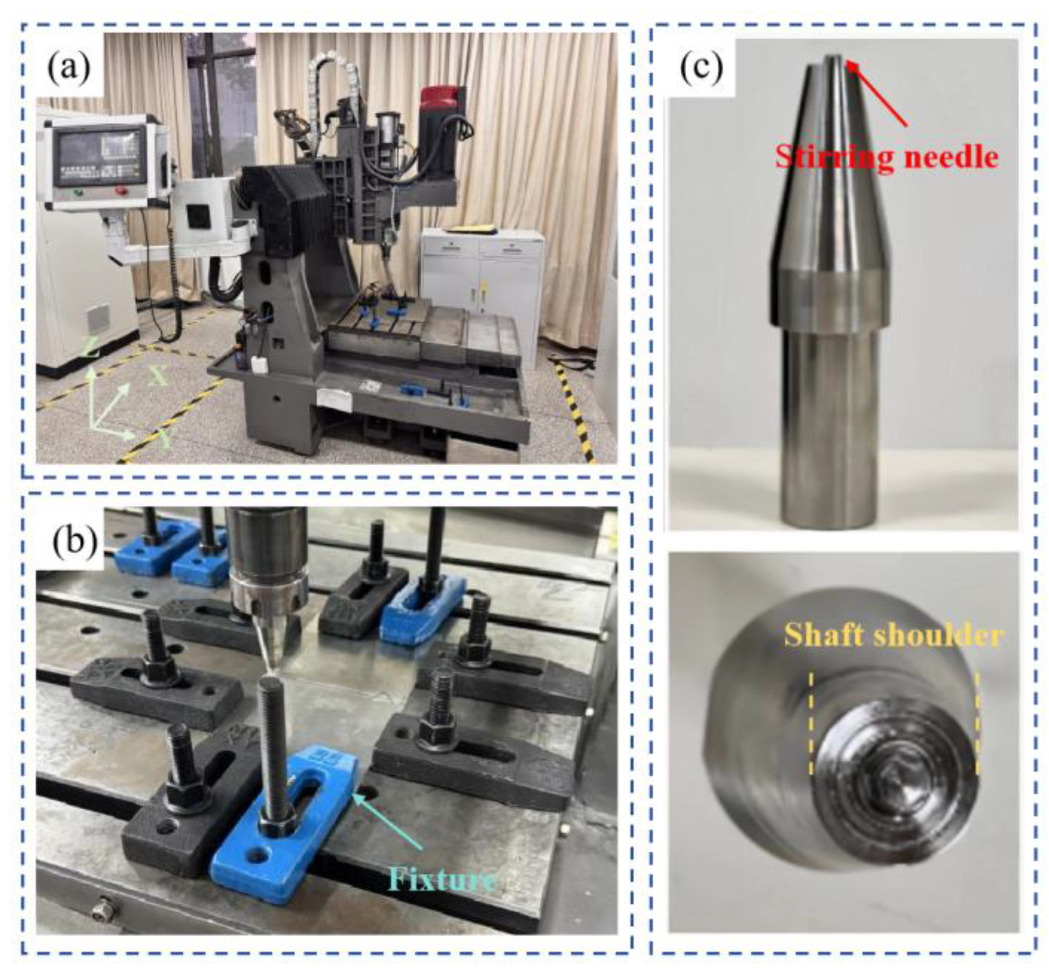
Figure 2.
Schematic diagram of the welding process: (a) Single-sided friction stir welding; (b) Double-sided co-directional friction stir welding; (c) Double-sided counter-directional friction stir welding.
Figure 2.
Schematic diagram of the welding process: (a) Single-sided friction stir welding; (b) Double-sided co-directional friction stir welding; (c) Double-sided counter-directional friction stir welding.
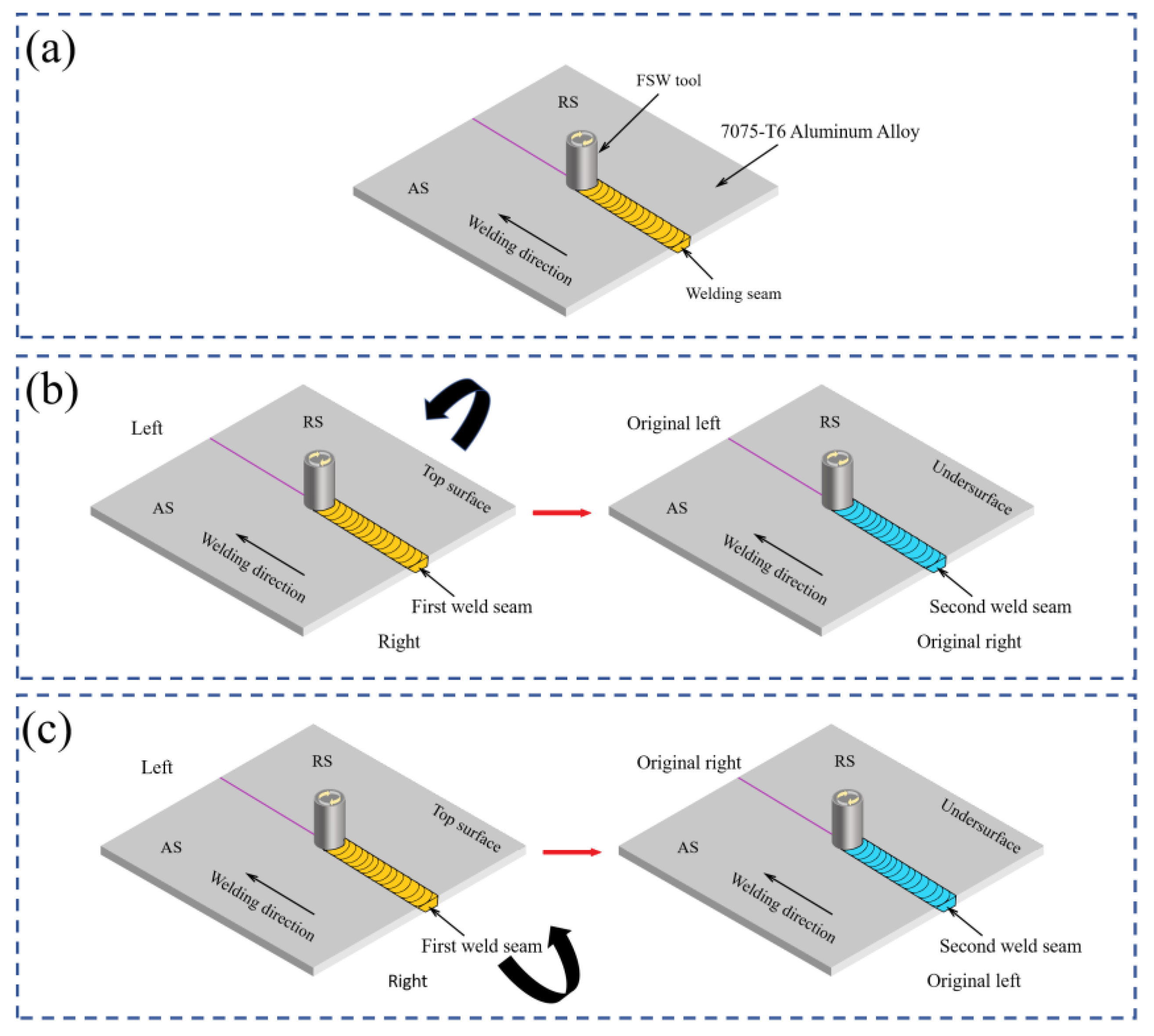
Figure 3.
(a) Schematic diagram of Vickers hardness indentations on cross-sectional microstructure; (b) Dimensions of tensile specimen; (c) Schematic diagram of sampling for tensile specimens and metallographic specimens.
Figure 3.
(a) Schematic diagram of Vickers hardness indentations on cross-sectional microstructure; (b) Dimensions of tensile specimen; (c) Schematic diagram of sampling for tensile specimens and metallographic specimens.
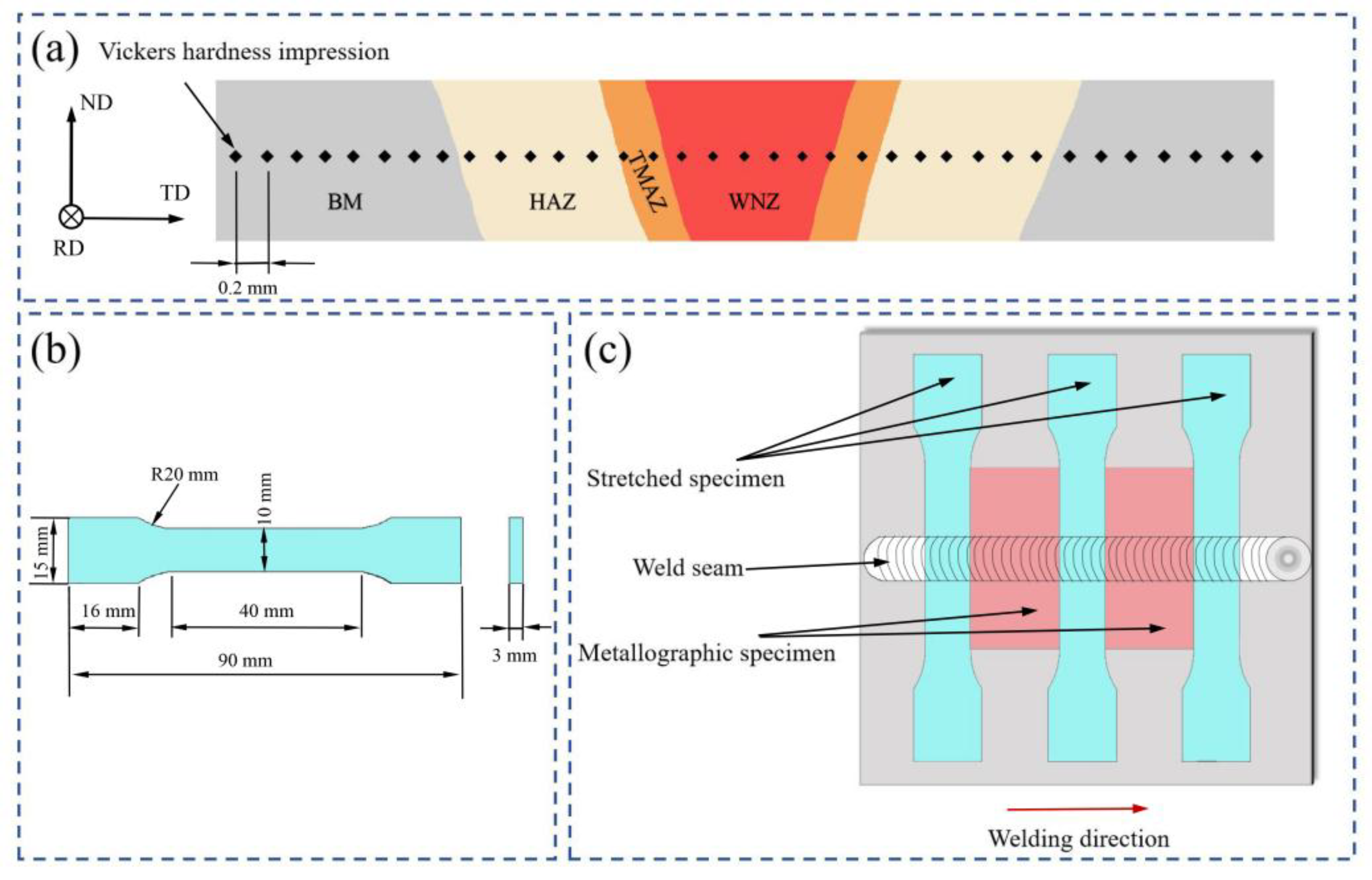
Figure 4.
Macroscopic appearance of welds under three welding paths: (a) SS-FSW; (b) DS-CD-FSW; (c) DS-CtD-FSW.
Figure 4.
Macroscopic appearance of welds under three welding paths: (a) SS-FSW; (b) DS-CD-FSW; (c) DS-CtD-FSW.
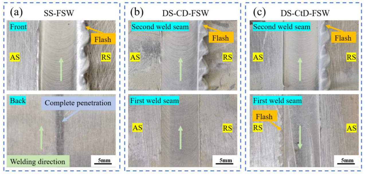
Figure 5.
Cross-sectional morphology of joints under three welding paths: (a) SS-FSW; (b) DS-CD-FSW; (c) DS-CtD-FSW.
Figure 5.
Cross-sectional morphology of joints under three welding paths: (a) SS-FSW; (b) DS-CD-FSW; (c) DS-CtD-FSW.
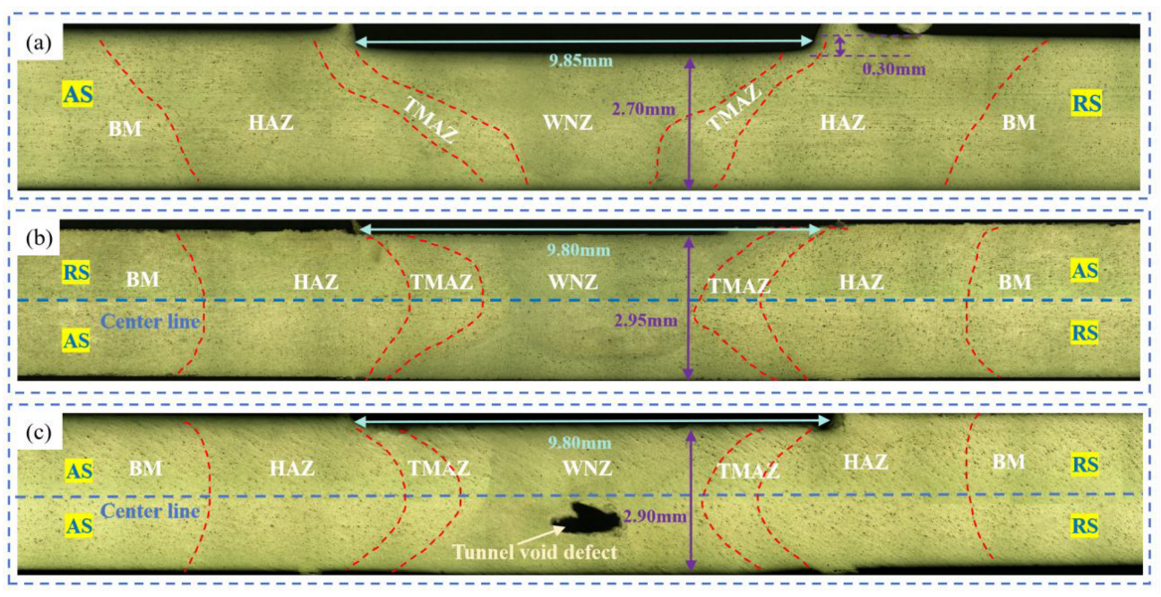
Figure 6.
Metallographic images of each zones of the joints under three welding paths. BM (a, e, i), HAZ (b, f, j), TMAZ (c, g, k) and WNZ (d, h, l).
Figure 6.
Metallographic images of each zones of the joints under three welding paths. BM (a, e, i), HAZ (b, f, j), TMAZ (c, g, k) and WNZ (d, h, l).
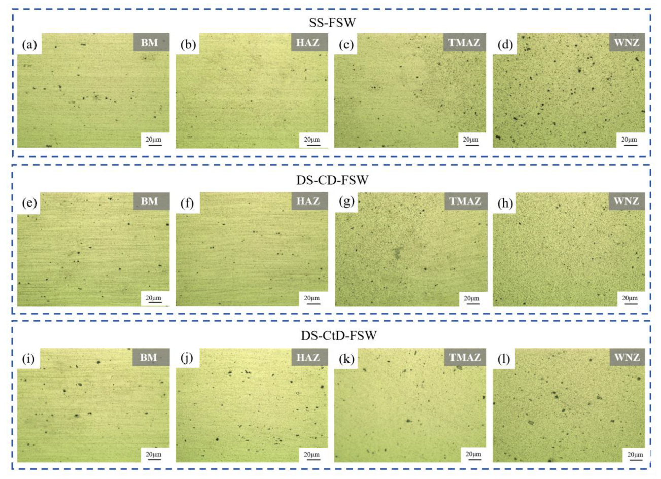
Figure 7.
IPF maps and grain size distribution histogram of each zones in DS-CD-FSW joint of 7075-T6 aluminium alloy: BM (a, b), HAZ (c, d), TMAZ (e, f), WNZ (g, h).
Figure 7.
IPF maps and grain size distribution histogram of each zones in DS-CD-FSW joint of 7075-T6 aluminium alloy: BM (a, b), HAZ (c, d), TMAZ (e, f), WNZ (g, h).
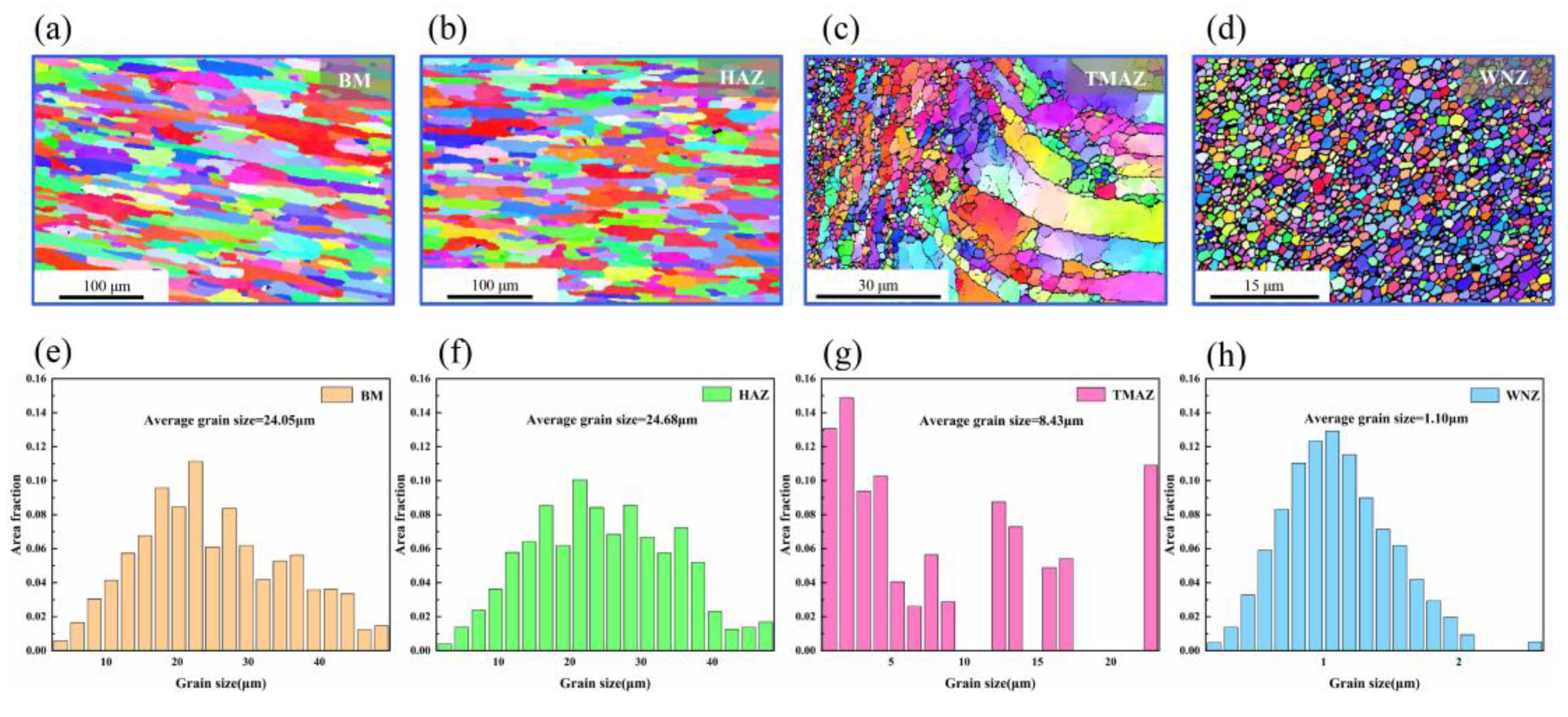
Figure 8.
GB maps and grain orientation difference distribution histograms of each zones in DS-CD-FSW joint of 7075-T6 aluminium alloy: BM (a, b), HAZ (c, d), TMAZ (e, f), WNZ (g, h).
Figure 8.
GB maps and grain orientation difference distribution histograms of each zones in DS-CD-FSW joint of 7075-T6 aluminium alloy: BM (a, b), HAZ (c, d), TMAZ (e, f), WNZ (g, h).
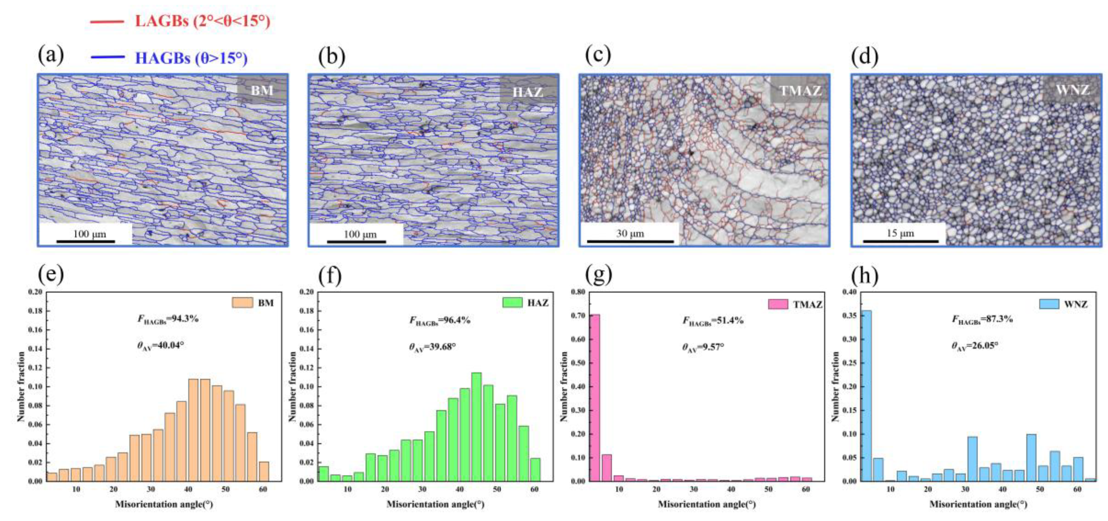
Figure 9.
GOS maps of each zones in the DS-CD-FSW joint of 7075-T6 aluminium alloy: (a) BM; (b) HAZ; (c) TMAZ; (d) WNZ.
Figure 9.
GOS maps of each zones in the DS-CD-FSW joint of 7075-T6 aluminium alloy: (a) BM; (b) HAZ; (c) TMAZ; (d) WNZ.
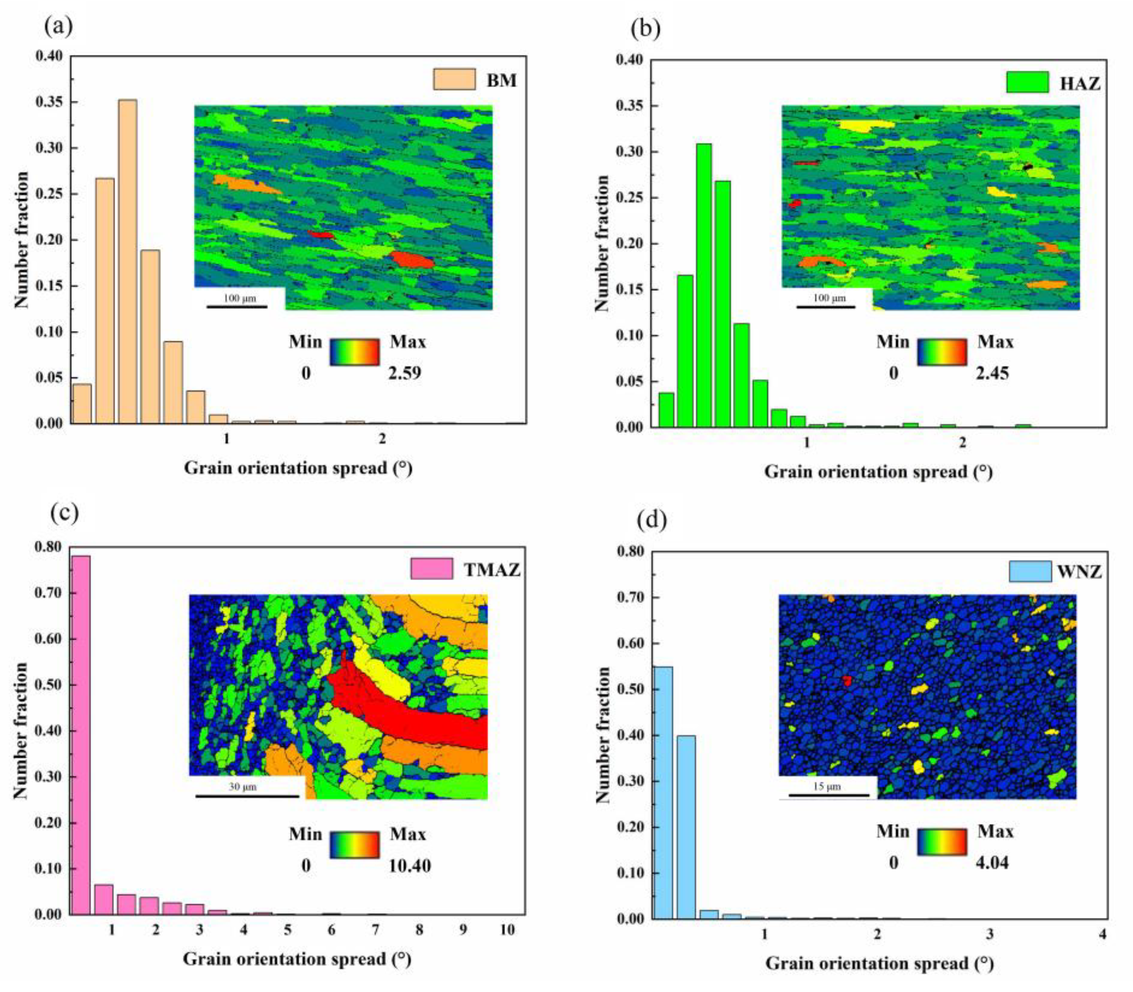
Figure 10.
KAM maps of each zones in DS-CD-FSW joint of 7075-T6 aluminium alloy: (a) BM; (b) HAZ; (c) TMAZ; (d) WNZ.
Figure 10.
KAM maps of each zones in DS-CD-FSW joint of 7075-T6 aluminium alloy: (a) BM; (b) HAZ; (c) TMAZ; (d) WNZ.
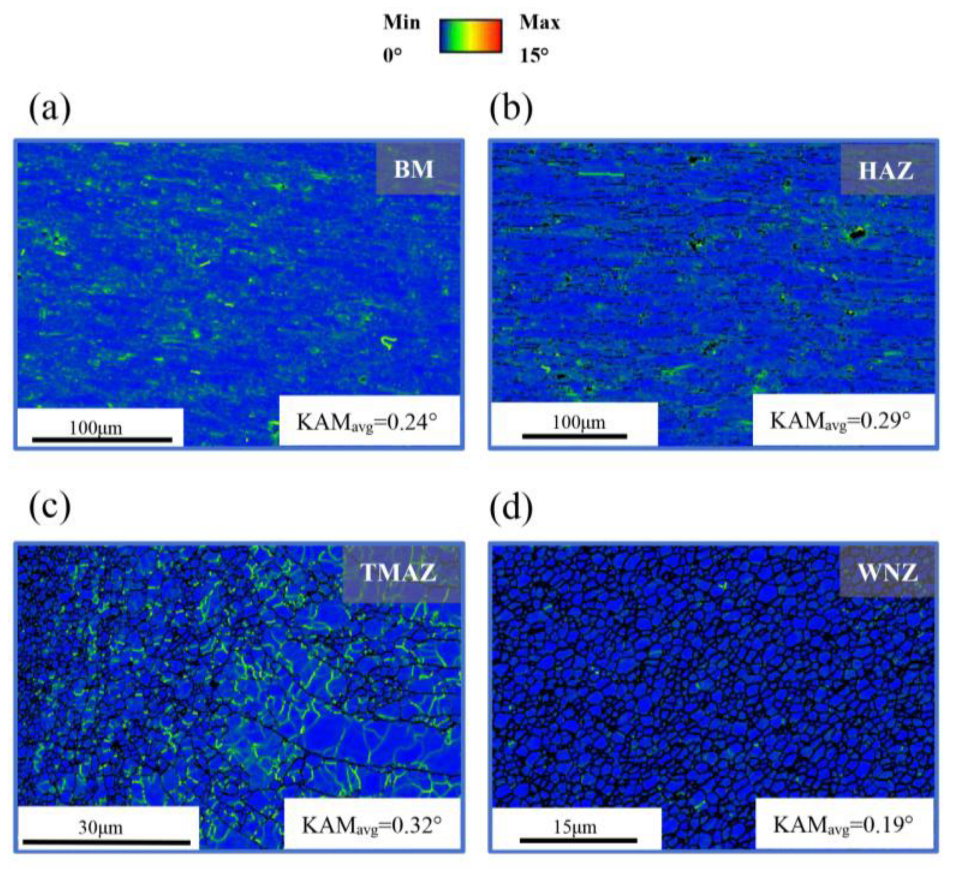
Figure 11.
PF maps and ODF maps of each zones of the joint: (a) BM; (b) HAZ; (c) TMAZ; (d) WNZ.
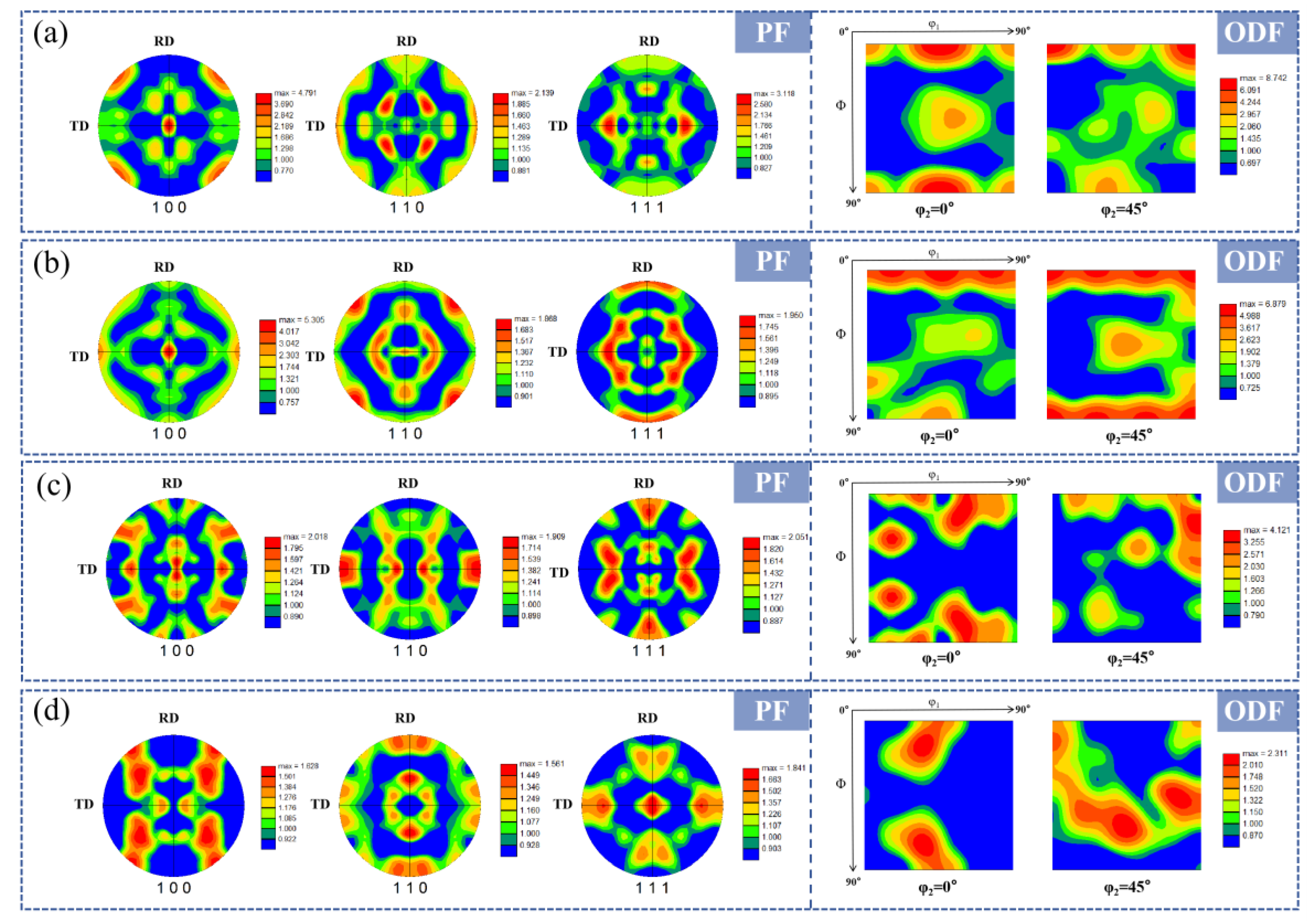
Figure 12.
XRD diffraction pattern.
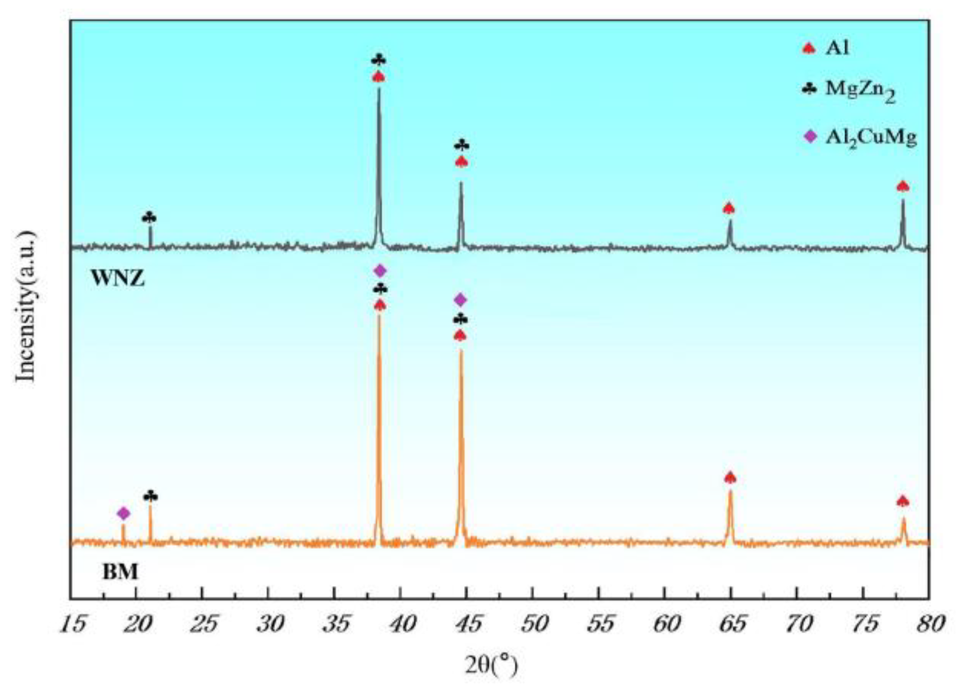
Figure 13.
Microhardness distribution of FSW joint cross-section: (a) SS-FSW; (b) DS-CD-FSW; (c) DS-CtD-FSW.
Figure 13.
Microhardness distribution of FSW joint cross-section: (a) SS-FSW; (b) DS-CD-FSW; (c) DS-CtD-FSW.
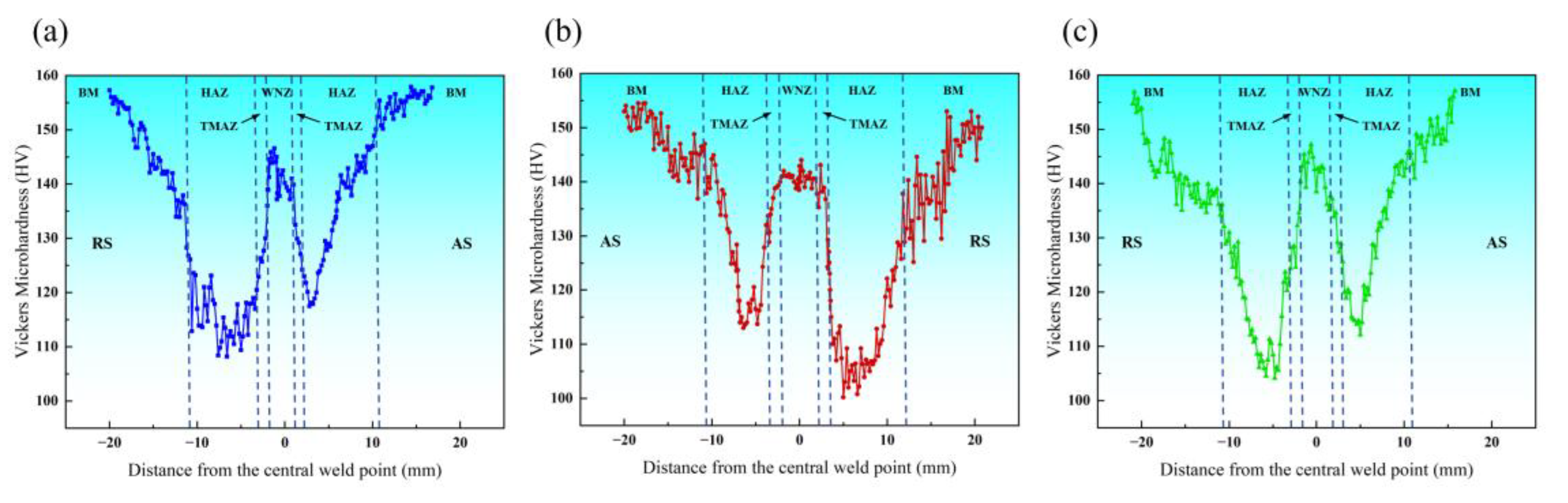
Figure 14.
(a) Tensile curves of joints and (b) summary of strength and elongation.
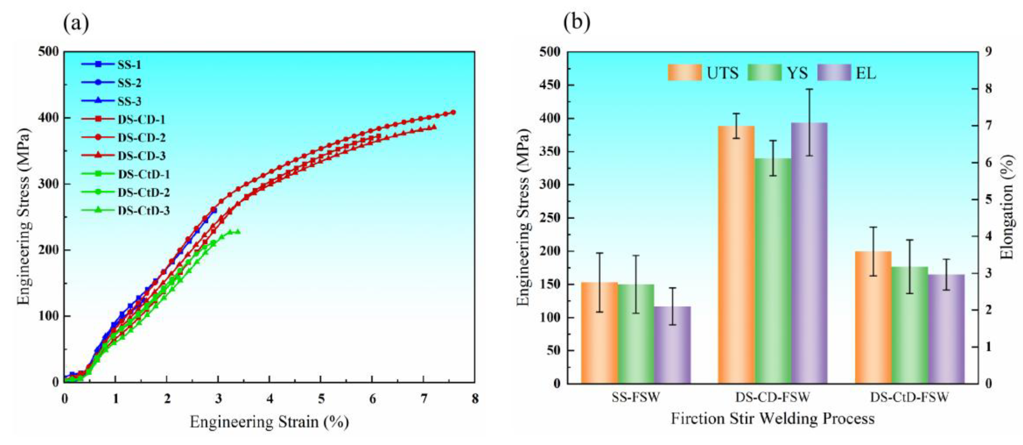
Figure 15.
SEM micrographs of tensile fracture surfaces of joints under three welding paths: (a) SS-FSW; (b) DS-CD-FSW; (c) DS-CtD-FSW.
Figure 15.
SEM micrographs of tensile fracture surfaces of joints under three welding paths: (a) SS-FSW; (b) DS-CD-FSW; (c) DS-CtD-FSW.
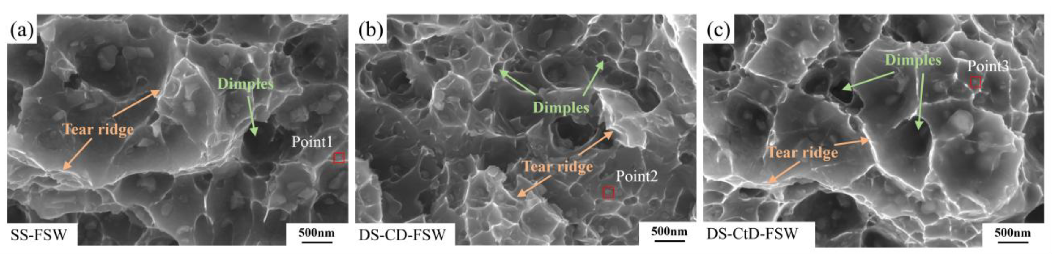

Table 1.
The main chemical composition of 7075-T6 aluminium alloy (wt %).
| Cu | Mg | Mn | Fe | Si | Cr | Zn | Ti | Al |
|---|---|---|---|---|---|---|---|---|
| 1.65 | 2.36 | 0.22 | 0.31 | 0.23 | 0.24 | 5.72 | 0.1 | Bal. |
Table 2.
Experimental welding parameters.
| Test number | Welding method | Rotational speed (r/min) |
Welding speed (mm/min) |
Plunge depth (mm) |
|---|---|---|---|---|
| 1 | SS-FSW | 1500 | 60 | 0.2 |
| 2 | DS-CD-FSW | 1500 | 80 | 0 |
| 3 | DS-CtD-FSW | 1500 | 80 | 0 |
Table 3.
Results of EDS spectrum detection of the stretched fracture.
| Point1 | Point2 | Point3 | ||||
|---|---|---|---|---|---|---|
| Element | wt.% | at.% | wt.% | at.% | wt.% | at.% |
| Al | 89.56 | 93.44 | 90.23 | 93.92 | 88.55 | 93.09 |
| Zn | 5.96 | 2.57 | 5.69 | 2.45 | 7.20 | 3.12 |
| Mg | 2.81 | 3.25 | 2.57 | 2.97 | 2.63 | 3.07 |
| Cu | 1.68 | 0.74 | 1.51 | 0.67 | 1.62 | 0.72 |
Disclaimer/Publisher’s Note: The statements, opinions and data contained in all publications are solely those of the individual author(s) and contributor(s) and not of MDPI and/or the editor(s). MDPI and/or the editor(s) disclaim responsibility for any injury to people or property resulting from any ideas, methods, instructions or products referred to in the content. |
© 2025 by the authors. Licensee MDPI, Basel, Switzerland. This article is an open access article distributed under the terms and conditions of the Creative Commons Attribution (CC BY) license.
Copyright: This open access article is published under a Creative Commons CC BY 4.0 license, which permit the free download, distribution, and reuse, provided that the author and preprint are cited in any reuse.


