
Submitted:
17 December 2025
Posted:
17 December 2025
You are already at the latest version
Abstract
To address the challenges of insufficient frequency regulation resources and diverse response capabilities in the Yunnan power grid caused by large-scale integration of renewable energy, this paper proposes a cooperative frequency regulation strategy for a hybrid energy storage system incorporating electrolytic aluminum load. First, the frequency regulation model is established for the integrated system comprising electrolytic aluminum load, abandoned mine pumped storage power station, and electrochemical energy storage. A frequency regulation method for electrochemical energy storage is designed, considering control mode weighting factors and state-of-charge (SOC) recovery characteristics. Subsequently, an improved filter with variable filtering time constants is developed based on the area control error (ACE). The high-frequency and low-frequency signals output by the filter are compensated by electrochemical energy storage and abandoned mine pumped storage, respectively. Furthermore, a frequency regulation strategy accounting for frequency regulation zone division is designed. Finally, simulation results under typical scenarios demonstrate that the proposed strategy effectively improves the SOC characteristics of electrochemical energy storage and enhances the frequency regulation performance of the hybrid energy storage system (HESS), while preventing overcharging and over discharging to extend the lifespan of energy storage devices.
Keywords:
second frequency modulation
; aluminum smelter load
; composite energy storage
; variable filter time constant
; state of charge
1. Introduction
In June 2023, the National Energy Administration issued the "Blue Book on the Development of New-Type Power Systems," proposing the construction of a new-type power system with continuously increasing penetration of renewable energy to promote the green transition of the energy sector [1,2]. However, renewable energy sources such as wind and solar exhibit strong stochasticity and high volatility, and their large-scale grid integration may impact system frequency stability 3. Relying solely on conventional thermal power units is insufficient to mitigate frequency fluctuations in the new-type power system. Consequently, tapping into the frequency regulation potential from the source-load-storage sides has become a research focus for scholars worldwide 4. As a technologically mature and widely deployed energy storage system (ESS), pumped storage serves as a critical solution for grid frequency regulation and peak shaving 5. Given the abundance of abandoned mines in northwestern and southwestern China, proposals have been made in recent years by researchers to repurpose the extensive underground spaces of these mines into pumped storage power stations 6. Compared with conventional pumped storage power stations, which are constrained by geographical conditions, water resource distribution, and the risk of damaging the surrounding ecological environment, abandoned mine pumped storage power stations offer advantages such as lower construction costs, reduced environmental impact, and more efficient land use [7,8]. From the perspective of resilient mining area distribution networks, a frequency regulation strategy based on the coordinated control of abandoned mine pumped storage and supercapacitors has been proposed in one study 9, which can effectively maintain the frequency stability of mining area power grids. Based on distributed coal mine underground reservoir technology, a peak-shaving system for abandoned mine pumped storage power stations was constructed 10. In one study, a HESS integrating abandoned mine pumped storage, batteries, and photovoltaics was developed, and an optimized scheduling strategy proposed based on this system significantly improved the photovoltaic accommodation rate 11. Given that the response time, reserve capacity, and regulation rate of pumped storage struggle to meet the multi-timescale frequency regulation demands of new-type power systems, the introduction of new types of energy storage for grid frequency regulation is hence required.
Electrochemical energy storage (EES) has become a crucial frequency regulation resource for renewable energy power plants owing to its advantages such as rapid response and long cycle life 12. However, a single energy storage technology alone is often inadequate to meet the frequency regulation requirements of power grids with a high penetration of renewable energy. The abundant mining resources in the Yunnan region, coupled with the rapid deployment of EES projects, create favorable conditions for investigating HESS that integrate electrochemical and pumped storage technologies. Meanwhile, the National Energy Administration has explicitly emphasized the need to develop diversified new types of energy storage to enhance the balancing capability of the power system 13. In the field of HESS, existing research has primarily focused on suppressing minor frequency fluctuations through improved filtering algorithms or optimized control strategies [14,15,16]. However, under large disturbance scenarios, the recovery speed and maximum frequency deviation suppression capability of these methods remain inadequate. The introduction of load-side resources, such as flexible industrial loads like electrolytic aluminum, can effectively expand the scope of frequency regulation resources.
Electrolytic aluminum load, with its advantages of rapid response characteristics and large power capacity, represents an ideal high-quality frequency regulation resource for the Yunnan power grid 17. Prior studies have integrated such loads into frequency regulation through methods such as VSC-HVDC grid integration 18, utilization of voltage characteristics 19, or model predictive control 20, achieving certain positive results. However, as a high-energy-consumption load, frequent and independent response of electrolytic aluminum to renewable energy fluctuations may adversely affect production stability and power quality. Therefore, achieving coordinated control between hybrid energy storage systems and electrolytic aluminum loads is crucial for enhancing system frequency resilience.
In view of this, this paper proposes a coordinated frequency regulation strategy for a HESS incorporating electrolytic aluminum loads. First, a joint system secondary frequency regulation model is established with the hybrid energy storage as the research object, integrating electrochemical energy storage, abandoned mine pumped storage power stations, and electrolytic aluminum industrial loads. Second, the frequency regulation commands for the hybrid energy storage are allocated using a variable time constant filter. Further considering the state of charge constraints of battery energy storage and the water storage status of pumped storage, a coordinated secondary frequency regulation strategy for hybrid energy storage incorporating electrolytic aluminum loads is designed. Finally, the effectiveness of the proposed strategy is verified through a typical simulation case.
2. Frequency Regulation Control Model of HESS with Electrolytic Aluminum Loads
2.1. Thermal power unit model
Upon receiving a frequency regulation signal, a thermal power unit sequentially delivers active power output through its governor and reheat turbine system. The corresponding frequency response model is given by:
(1)
where: TG is the thermal unit governor time constant; FHP, TRH, TCH, are the reheater gain, heater time constant and turbine time constant, respectively; s is the Laplace transform operator.
The transfer function of the generator and load is modeled as:
(2)
where: H is the generator inertia time constant, and D is the load damping factor.
2.2. Composite Energy Storage Model
2.2.1. Abandoned Mine Pumped Storage Plant Model
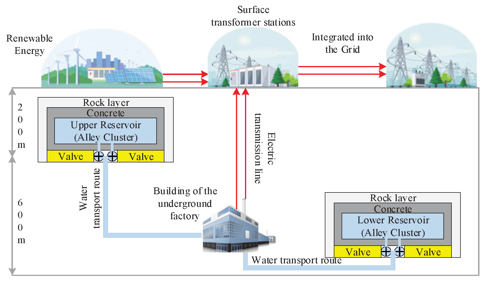
Currently, abandoned mine pumped storage power stations can be classified into semi-underground and fully-underground types, with capacities categorized as large-scale (10²–10³ MW) and small-to-medium-scale (10⁻²–10² MW). Considering the head conditions of mines in Yunnan and the low evaporation characteristics of underground reservoirs, this study adopts a small-to-medium-scale fully-underground configuration. The upper and lower reservoirs are constructed in tunnel networks and goaf areas at depths of 200 m and 800 m underground, respectively 23. As illustrated in Fig. 1, both the upper and lower reservoirs of the power station are formed by tunnel networks, protected externally by concrete and rock mass. They are connected to the underground powerhouse through valves and water conveyance tunnels, with the generated power eventually integrated into the grid alongside other energy sources.
Figure 1.
Illustration of a comprehensive pumped-hydro storage facility built within a decommissioned subterranean mine.
Figure 1.
Illustration of a comprehensive pumped-hydro storage facility built within a decommissioned subterranean mine.
The turbine transfer function for the case can be expressed as:
(3)
where: TW is the water flow inertia time constant.
The governor systems for hydraulic turbines are broadly categorized into electro-hydraulic and mechanical-hydraulic types. Given its closer alignment with the operational characteristics of modern hydroelectric generating units, the electro-hydraulic governor is selected for investigation in this study. Its transfer function is expressed as Eq. (4).
(4)
where: TH is the governor time constant of the hydraulic turbine; Kp , Ki and Kd are the proportional, differential and integral coefficients of the governor respectively; R is the turbine's modulation coefficient.
2.2.2. Electrochemical Energy Storage Model
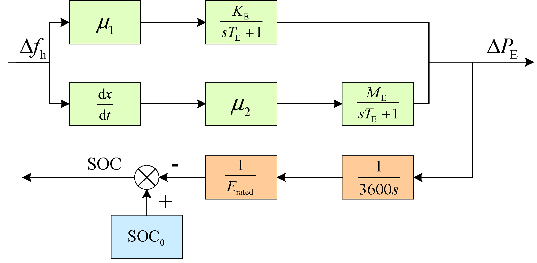
The transfer function model of electrochemical energy storage is shown in Fig. 2. This model represents the electrochemical energy storage system as a first-order inertial element, which is commonly used to analyze its capability to participate in system frequency response. The mathematical representation is given by:
(12)
(13)
(14)
(15)
(16)
where: GE(s) is the transfer function model of the electrochemical energy storage; TE is the battery delay response time constant; , ΔPE, ΔPKE and ΔPME are the regulation output, virtual sag output and virtual inertia output of the electrochemical energy storage, respectively; μ1, μ2 are the weight factors of the virtual sag and virtual inertia control, respectively; KE, ME are the virtual sag coefficients and the virtual inertia coefficients of the electrochemical energy storage, respectively; Δfh is the high-frequency frequency after the frequency dividing process; SOC(t), SOC0, and SOC0 are the charge state quantity of the electrochemical energy storage, and initial time, respectively; Erated is the total electric quantity of the electrochemical energy storage.
Figure 2.
Transfer function diagram of electrochemical energy storage
2.3. Aluminium Electrolysis Load Model
Figure 3 illustrates the circuit configuration of the electrolytic aluminum load employing self-saturating reactor control technology 24. The model primarily consists of three components: the electrolytic cell, control winding, and Buck chopper circuit. This configuration not only maintains the economic efficiency of the electrolysis process but also enhances the precision of power regulation.
The state space equation of the electrolytic aluminium load is:
(17)
where: state variable x=[Ib, Uc, Ic, Ud, Id] , ẋ is the derivative of the state variable; input u=[d], d is the duty cycle; y is
the output.
3. Proposed Secondary Frequency Regulation control strategy for electrochemical energy storage
The control strategy for electrochemical energy storage participating in secondary frequency regulation, as proposed in this paper, is illustrated in Figure 5. This strategy initially detects whether the ACE exceeds the deadband. If not, the reserve capacity of thermal power units is utilized to optimize the SOC of the energy storage system, thereby preventing overcharging or over-discharging. When the ACE exceeds the deadband, it is decomposed into high-frequency and low-frequency components via a variable time constant filter. Based on the high-frequency component and its rate of change, the energy storage system adaptively adjusts the weighting coefficients of virtual droop and inertia control to rapidly suppress frequency fluctuations.
3.1. Frequency Regulation control method based on weighting factors
During secondary frequency regulation, the coordinated action of the two control strategies must be ensured, and their weighting coefficients need to be determined in practical applications. To this end, a fuzzy logic control method is adopted in this paper to dynamically compute the weights of the two control modes. The weighting factors μ₁ and μ₂ are dynamically calculated based on the system frequency deviation and its rate of change, with real-time outputs provided by the fuzzy logic controller. The structure of this controller is illustrated in Figure 7.

Table 1.
Fuzzy control rules for high frequency signal and its rate of change.
| d∆fh | ∆fh | ||||||
| NL | NM | NS | Z | PS | PM | PL | |
| NL | VB | M | B | VB | Z | Z | Z |
| NM | B | B | B | B | M | S | S |
| NS | S | M | B | B | S | S | S |
| Z | Z | Z | Z | Z | Z | Z | Z |
| PS | S | S | S | B | B | M | S |
| PM | S | S | M | B | B | B | B |
| PL | Z | Z | Z | VB | B | M | VB |
After normalization of the input and output variables, the universe of discourse for both input variables |Δfh| and |dΔfh| is defined as [-1, 1], while the output variable λ is defined over [0,1]. The fuzzy subsets for both input variables are {NB, NM, NS, Z, PS, PM, PB}, and for the output variable are {Z (Zero), S (Small), M (Medium), B (Large), VB (Very Large)}. Triangular membership functions are adopted for all input and output variables.
After obtaining the weighting coefficient λ, it is fed into the adaptive controller together with the high-frequency signal and its rate of change. Following the adaptive selection process, the virtual droop weighting factor μ₁ is derived as shown in Eq. (20), while the virtual inertia weighting factor μ₂ is determined according to Table 2.
(20)
After determining the weighting factors, the virtual inertia coefficient and virtual droop coefficient must be calculated according to Eq. (13)–(15). To prevent overcharging or over-discharging, which can adversely affect the service life of the energy storage system, the State of Charge (SOC) is considered during secondary frequency regulation. In this paper, the SOC is divided into six ranges: minimum (Smin), relatively low (S₀), moderately low (Slow), moderately high (Shigh), relatively high (S₁), and maximum (Smax). Taking the virtual droop control coefficient KE as an example, this coefficient comprises both a charging control coefficient Kc and a discharging control coefficient Kd. When the SOC is in the optimal range, i.e., S(t) ∈ (Slow, Shigh), KE is set to its maximum value. The charging and discharging coefficients for the virtual droop control are given by Eq. (21) and (22), respectively:
(21)
(22)
where: KE,max is the maximum value of the virtual sag control coefficient, α and β are both adaptive factors.
In order to make the output of virtual sag control and virtual inertia control in electrochemical energy storage appropriate, this paper makes the virtual inertia coefficient equal to the virtual sag coefficient, i.e., KE=ME。
3.2. Power Recovery Method Considering SOC and Frequency Deviation Constraints
During secondary frequency regulation, when the ACE frequency deviation signal ΔfACE remains within the deadband and the State of Charge (SOC) is in an undesirable condition, a recovery coefficient must be calculated based on the SOC. This coefficient directs the energy storage SOC toward an optimal range while preventing ΔfACE from exceeding the normal regulation zone during the recovery process.
1) SOC constraints
From the perspective of the energy storage system's intrinsic recovery needs, and to facilitate the analysis of its recovery demand coefficient under different SOC levels, the recovery output depth is determined based on the current SOC. The charging and discharging recovery demand coefficients, Rc1 and Rd1, calculated according to the SOC, are given by Eq. (23) and (24), respectively.
(23)
(24)
2) Frequency deviation constraint
Since the SOC has to avoid the system frequency exceeding the frequency regulation dead zone when recovering, from the recovery constraint of the system, in order to facilitate the analysis of the memory recovery constraint coefficients under different ACE frequency deviation signals, the h is partitioned, i.e , , , , , , , correspond to the lower dead band limit, the minimum value, the smaller value, the smaller value, the larger value, the larger value and the maximum value of the ACE frequency deviation signals, respectively, the upper dead band limit, different ACE frequency deviation signal intervals correspond to different recovery constraint coefficients0, and the charging and discharging recovery constraint coefficients calculated based on the ACE frequency deviation signals are shown in (25) - (26), respectively.
(25)
(26)
To ensure grid frequency remains within permissible limits during the recovery of the energy storage system's output power, an integrated consideration of both the battery's SOC recovery requirements and the power system's load-bearing limit is required. The corresponding SOC recovery coefficient is specified in Eq. (27).
(27)
3) SOC recovery factor
Once the SOC recovery coefficient is determined, the recovery output power of the energy storage system can be calculated to restore the State of Charge (SOC) of the electrochemical energy storage to its optimal range. The recovery output power for the electrochemical energy storage SOC is expressed as Eq. (28).
(28)
4. Cooperative Frequency Regulation Strategies for Composite Energy Storage Systems Considering Aluminum Loads
4.1. Control strategy for composite energy storage system based on variable filter time constant
To address the issues of SOC limit violations in electrochemical energy storage and frequent start-stop operations of pumped storage units in hybrid energy storage systems, this paper proposes an adaptive frequency allocation strategy based on the rate of change of ACE. This strategy decomposes the frequency deviation signal through an adaptive filter and allocates the components to pumped storage (low-frequency) and electrochemical energy storage (high-frequency), respectively, enabling coordinated frequency regulation. The filter expression is given by Eq. (29).
(29)
where: TN0 is the initial value of the filter time constant; ΔTN is the variation of the filter time constant.
Figure 9.
ΔTN and |dΔfACE/dt| curves.
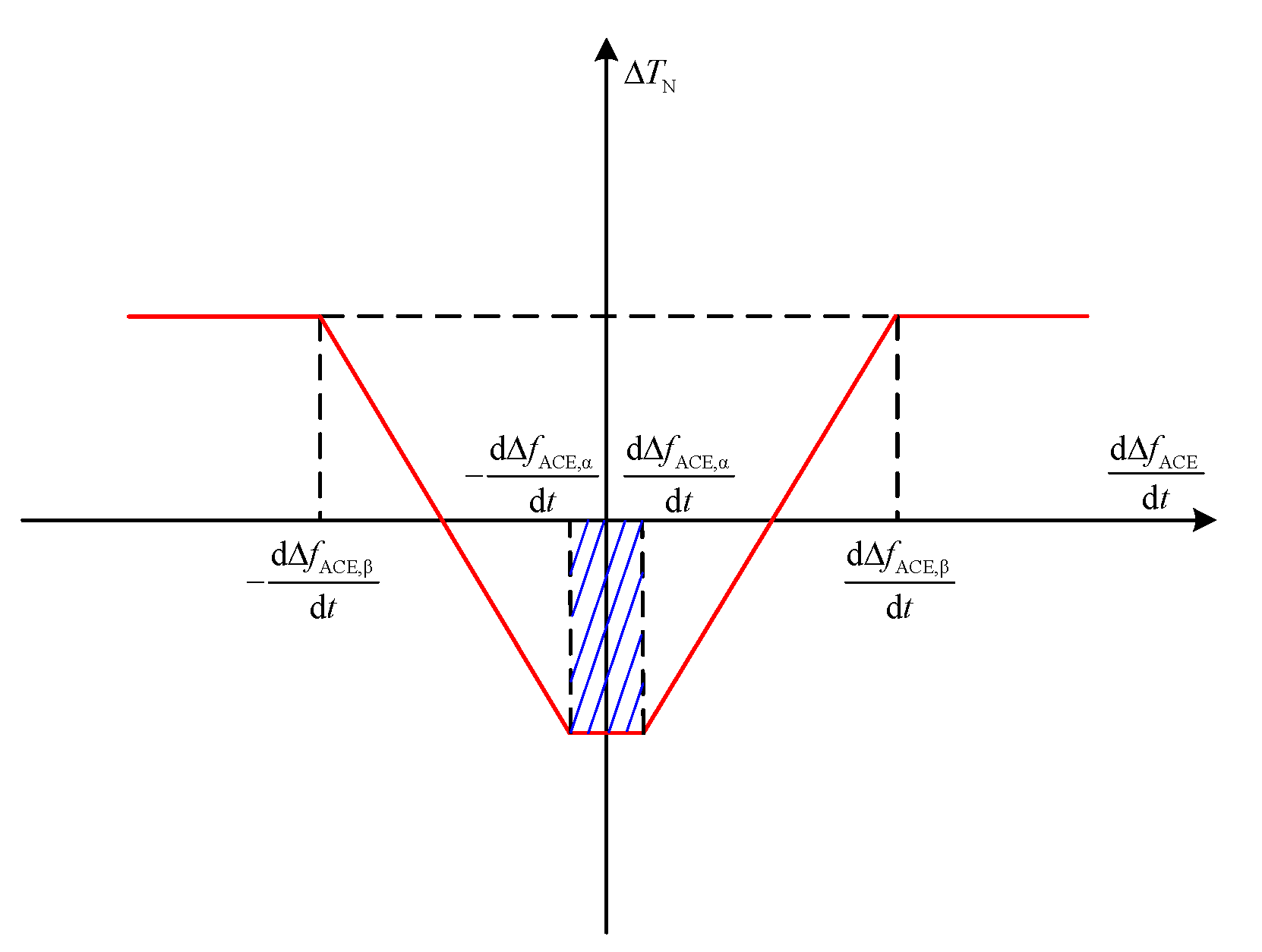
Based on the relationship curve between the filter time constant and the rate of change of the ACE frequency deviation, their corresponding relationship is expressed by Eq. (21). To facilitate subsequent simulation data processing, the rate of change of the ACE frequency deviation is normalized in this study, with dΔfACE,α/dt and dΔfACE,β/dt set to 0.1 and 0.9, respectively.
(30)
4.2. Control strategy for composite energy storage system based on variable filter time constant
When load fluctuations in the power grid result in power deficit or surplus, different frequency regulation resources respond to the commands of the coordinated control strategy by adjusting their active power to achieve power balance of the electrical power system. The ACE interval partitioning strategy is illustrated in Figure 10.
(1) When |Δf |≤Δfdb, the grid operates within the regulation deadband. In this scenario, only the electrochemical energy storage performs SOC recovery, while other frequency regulation resources remain inactive. This maintains the energy storage SOC within the optimal range, thereby preventing overcharging or over-discharging.
(2) When Δfdb<| Δf |≤ΔfCES, the grid enters the normal regulation zone. During this condition, only conventional thermal power units participate in frequency regulation.
(3) When ΔfCES<| Δf |≤ΔfAL, the grid operates in the sub-emergency regulation zone. Under such circumstances, the hybrid energy storage system assists conventional thermal power units in grid frequency regulation. A variable-filter time constant controller decomposes the ACE frequency deviation signal into high-frequency and low-frequency components, with the low-frequency component handled by abandoned mine pumped storage plants and the high-frequency component managed by electrochemical energy storage.
(4) When ΔfAL<| Δf |≤ΔfOVER, the grid enters the emergency regulation zone. Here, restoring grid frequency takes the highest priority, with conventional thermal power units, the hybrid energy storage system, and electrolytic aluminum loads jointly participating in frequency regulation.
(5) When | Δf |>ΔfOVER, the grid reaches the super-emergency regulation zone. In this state, neither the hybrid energy storage system nor conventional thermal power units can suppress grid frequency fluctuations, and all frequency regulation resources fail to respond. Ultimately, system frequency can only be gradually restored to a safe range through forced load-shedding operations.
(31)
where: ΔP is the frequency regulation output of the load, ΔPG is the frequency regulation output of the thermal power units, and ΔPPPS is the frequency regulation output of the mine waste pumped storage power plants.
5. Simulation Analysis
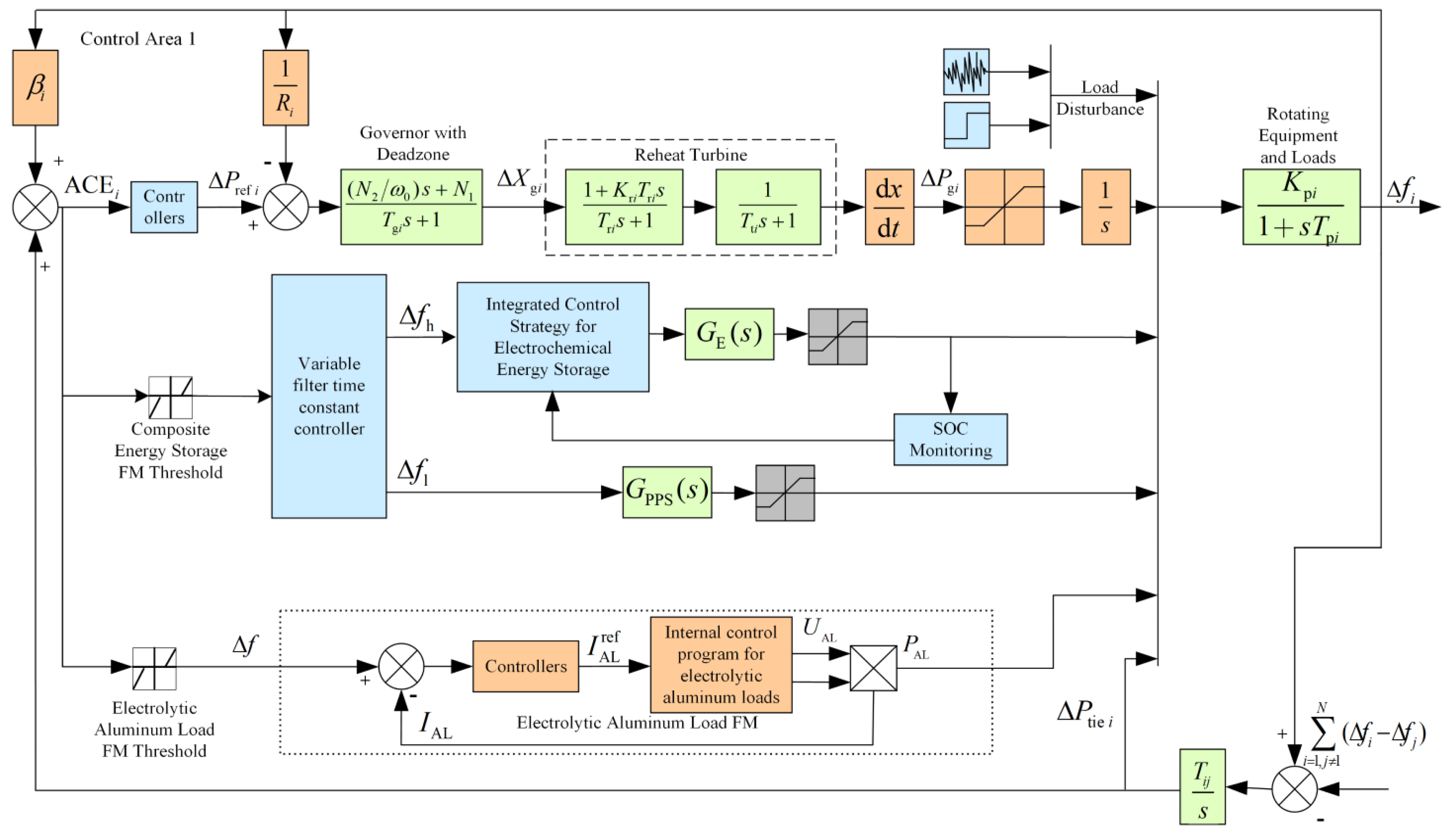
This paper models the frequency regulation process of a two-area system incorporating electrolytic aluminum loads and a hybrid energy storage system using the Matlab/Simulink simulation platform. The architecture of this model is shown in Fig. 11. The installed capacity of conventional thermal power units in the system is set to 500 MW. Area 1 is equipped with electrolytic aluminum loads and the hybrid energy storage system, where the electrolytic aluminum load has an installed capacity of 306 MW, and the remaining load in the system has an installed capacity of 194 MW.
Figure 11.
Cooperative control frequency response model of composite energy storage system with electrolytic aluminum load.
Figure 11.
Cooperative control frequency response model of composite energy storage system with electrolytic aluminum load.
5.1. Analyzing the Frequency Regulation Performance of the Variable Filter Time Constant Controller
A 5-minute continuous load fluctuation data segment from an actual power grid was applied as the analysis sample and introduced into the control area. In the simulation, the sampling period was set to 0.1 s, and the corresponding load disturbance profile is shown in Figure 12. To validate the effectiveness of the proposed controller, simulations were conducted under identical grid load fluctuations for three scenarios: without a filter, with a first-order low-pass filter, and with the proposed variable time constant filter. The simulation results are presented in Figure 13.
It is about 0.032Hz smaller than the case without filter, and the oscillation is reduced, but the regulation time is not significantly shortened. When the system adopts the variable filter time constant controller designed in this paper, the system oscillation is smaller, the control time is also shortened, and the maximum frequency difference is reduced to 0.02h4Hz, which verifies that the variable filter time constant controller has better dynamic continuous performance.
5.2. Simulation Analysis of Electrochemical Energy Storage Strategies
To verify the effectiveness of the electrochemical energy storage strategy proposed in this paper, the configured capacity of the electrochemical energy storage is set to 0.5 MWh and the initial SOC value is 0.5. After a sudden load increase of 0.04 p.u. at 6 s, the system enters the sub-emergency frequency regulation zone, at this time, it is necessary for the conventional unit, abandoned mine pumped storage and electrochemical storage to jointly participate in frequency regulation, and the proposed electrochemical storage frequency regulation strategy is compared with the fixed-K adaptive control and no storage, and the frequency deviation, electrochemical storage system output and its SOC change curves in the three scenarios are shown in Figure 14.
As can be seen from Figure 14, the load surges by 0.04 p.u. at 6 s. The frequency fluctuation deviation of the system is large when relying solely on the conventional frequency regulation unit, and the maximum frequency difference reaches 0.135 Hz. When the electrochemical energy storage added to the composite energy storage system is controlled by fixed-K adaptive control, the maximum frequency deviation of the system is reduced to 0.063 Hz, whereas the system frequency deviation is limited to 0.05 Hz when the electrochemical energy storage strategy proposed in this paper is used. Meanwhile, the storage power under the proposed electrochemical energy storage strategy is reduced by 17% compared to the fixed K adaptive control, and its SOC is improved by 9.8% compared to the fixed K adaptive control, which avoids overcharging and overdischarging of the electrochemical energy storage, and results in better maintenance of the SOC of the electrochemical energy storage system.
5.3. Cooperative control strategy Participation in grid frequency control performance analysis
Assuming that the grid is initially under normal operation, the load increases suddenly by 0.05 p.u. at 6 s. At this time, the system is in the emergency regulation zone due to excessive load increment, which requires the joint participation of conventional thermal power units, abandoned mine pumped storage power stations, electrochemical energy storage and electrolytic aluminium loads in frequency regulation, and the simulation results are shown in Fig. 15.
As shown in Figure 15, the maximum frequency difference is 0.195 Hz when relying on the conventional frequency regulation unit alone in emergency situations. Under the two scenarios of relying only on waste mine pumped storage for frequency regulation and using composite energy storage for frequency regulation, the maximum frequency difference is reduced to 0.155 Hz and 0.112 Hz, respectively, which significantly improves the frequency regulation performance compared with that when only the conventional unit is used for frequency regulation, and the value of the maximum frequency difference is further reduced to 0.054 Hz after adopting the method proposed in this paper. At the same time, the method proposed in this paper is able to reduce the depth of action of the waste mine pumped storage and electrochemical energy storage compared to conventional methods and relying on a single frequency regulation source. In the strategy proposed in this paper, the power of the aluminium electrolytic load is reduced from 306 MW to 297 MW, releasing 9 MW of active power, and under the action of the aluminium electrolytic load, the tailings pumped storage plant and the electrochemical storage have a faster response and a smaller depth of action, which reduces mechanical wear of the tailings pumped storage plant, avoids overcharging or overdischarging of the electrochemical storage, and extends their life.
6. Conclusions
In this paper, for the problem of insufficient system frequency regulation capacity and frequency response capability due to the increasing penetration of new energy in the power grid, a cooperative control strategy for a composite energy storage system containing electrolytic aluminium load is proposed, and the following conclusions are drawn:
1) A variable filtering time constant controller is introduced to address the stochasticity and volatility introduced by the large-scale integration of new energy sources into the grid. Compared with traditional unfiltered control and first-order low-pass filter control, the variable filter time constant controller has better dynamic characteristics and optimizes system performance well and at high speed.
2) The electrochemical energy storage device makes full use of the responsiveness of the virtual inertia and virtual sag to the frequency deviation and its rate of change, which effectively improves the frequency recovery speed, and at the same time improves the SOC of the electrochemical energy storage device, avoids overcharging and over discharging, and effectively improves the service life of the energy storage power supply.
3) The cooperative control method is designed based on the consideration of the response characteristics of electrolytic aluminium load and composite energy storage, which can effectively reduce the maximum frequency difference of the system, suppress the system frequency fluctuation faster, enhance the robustness of the system, and further ensure the stable operation of the power system compared with the traditional method and the control of a single frequency regulation resource.
With the new power system and " carbon peaking and carbon neutrality " goals of continuous promotion, the grid frequency stability problem is becoming more and more prominent, this paper only from the theoretical level to consider the electrolytic aluminium load, abandoned mine pumping station and electrochemical energy storage and other resources to participate in the grid secondary frequency regulation, in order to ensure that the composite energy storage and electrolytic aluminium loads to participate in the frequency regulation auxiliary services market, the composite energy storage Optimal capacity allocation, relevant government policies and operation mechanisms still need to be further studied.
Author Contributions
W. T., Conceptualization, validation, ; writing—original draft preparation; X. L., validation, ; writing—original draft preparation, formal analysis; Y. L., validation, writing—original draft preparation; X. M., investigation, funding acquisition; Z. S., investigation, writing—original draft preparation; H. Y. , writing—original draft preparation; G. L., writing—original draft preparation; Z. L., funding acquisition, writing—original draft preparation.
Funding
This research received no external funding by the National Natural Science Foundation of China (No. 52277104); Science and Technology Project of China Southern Power Grid Co., Ltd (No. YNKJXM20230453);Yunnan Major Scientific and Technological Projects (No. 202402AF080006); Yunnan Fundamental Research Projects (No. 202301AT070455).
Data Availability Statement
All data supporting the findings of this study are included within the article. The original results presented here are fully contained in this publication, and any further inquiries may be directed to the corresponding author.
Conflicts of Interest
The authors declare no conflicts of interest.
Abbreviations
The following abbreviations are used in this manuscript:
| SOC | State of Charge |
| ACE | Area control error |
| HESS | Hybrid Energy Storage System |
| ESS | Energy Storage System |
| EES | Electrochemical Energy Storage |
References
- Xinxin Li, Yingzi Li, Qinliang Tan, Shuo Zhang, Bi-objective robust dispatch model for virtual power plant with security-economy-green equilibrium in the new-type power system, Energy Conversion and Management, Volume 344, 2025, 120253. [CrossRef]
- National Energy Administration. A blue book on the development of the new power system [EB]. [2023- 06- 02]. http://www.nea.gov.cn/2023-06/02/c_1310724249.htm.
- J. Hu, X. Liu, M. Shahidehpour and S. Xia, "Optimal Operation of Energy Hubs With Large-Scale Distributed Energy Resources for Distribution Network Congestion Management," in IEEE Transactions on Sustainable Energy, vol. 12, no. 3, pp. 1755-1765, July 2021. [CrossRef]
- J. Wang, W. Du, D. Yang, G. Liu and H. Chen, "An Optimal Scheduling Method of Virtual Power Plant Cluster Considering Generation-grid-load-storage Coordination," 2021 6th Asia Conference on Power and Electrical Engineering (ACPEE), Chongqing, China, 2021, pp. 1048-1052.
- L. Shi, W. Lao, F. Wu, T. Zheng and K. Y. Lee, "Frequency Regulation Control and Parameter Optimization of Doubly-Fed Induction Machine Pumped Storage Hydro Unit," in IEEE Access, vol. 10, pp. 102586-102598, 2022. [CrossRef]
- X. Wu, W. Shang, Z. MA, et al. Coordinated control method for pumped and flywheel hybrid energy storage system[J]. Energy Storage Science and Technology, 2023, 12(02): 468-476.
- Yan Ren, Ketao Sun, Kai Zhang, et al. Optimization of the capacity configuration of an abandoned mine pumped storage/wind/photovoltaic integrated system, Applied Energy, Volume 374, 2024, 124089. [CrossRef]
- H. Xie, Z. Hou, F. Gao, et al. A new technology of pumped-storage power in underground coal mine: Principles, present situation and future[J]. Journal of China Coal Society, 2015, 40(05): 965-972.
- R. Zhong, S. Teng, R. Liang, et al. Research on Frequency Elasticity Enhancement Method of Mining Area Power Grid Based on Hybrid Energy Storage System[J]. Power System Technology, 2019, 43(07): 2291-2298.
- T. Li, D. Gu, J. Li, et al. Construction of pumped storage peak shaving system for mine water based on abandoned coal mine goaf[J]. Coal Science and Technology, 2018, 46(09): 93-98.
- Z. Liang, M. Li, M. Zhou, et al. Optimal scheduling strategy for PV-abandoned mine pumped storage-battery hybrid power generation system for PV energy consumption[J]. Science & Technology Review, 2021, 39(13): 52-58.
- X. Guo, C. Wang, W. Qian, et al. A Review of Equalization Methods for Battery Energy Storage System[J]. Transactions of China Electrotechnical Society: 1-22[2024-04-30].
- National Energy Administration. Transcript of the National Energy Administration's press conference in the first quarter of 2024 [EB/OL]. (2024-01-25) [2024-05-06]. https://www.nea.gov.cn/2024-01/25/c_1310762019.htm.
- S. Zhang, P. Li, Y. Zhang, et al. Secondary Frequency Modulation Strategy of Composite Energy Storage Based on Variable Filter Time Constant and Fuzzy Control[J/OL]. Journal of Shanghai Jiaotong University: 1-26[2024-04-30].
- J. Liu, S. Zhu, P. Liu, et al. Coordinated control strategy for wind turbine and energy storage equipment considering system frequency safety and stability constraints[J]. Power System Protection and Control, 2024, 52(01): 73-84.
- F. Zhu, X. Zhou, Y. Zhang, et al. A load frequency control strategy based on disturbance reconstruction for multi-area interconnected power system with hybrid energy storage system[J]. Energy Reports, 2021, 7: 8849-8857. [CrossRef]
- Z. Feng, S. Li, S. Zhu, et al. Frequency Regulation Signal Reduction Methods for Aluminum Smelters[J]. Journal of System Simulation, 2020, 32(12): 2332-2340.
- H. Su, S. Yang, M. Duan, et al. Sources-grid-load Cooperative Secondary Frequency Control Under Aluminum Smelter Loads Response[J]. Journal of Harbin University of Science and Technology, 2023, 28(06): 46-56.
- S. Liao, M. Zhang, J. Xu, et al. Frequency Stability Control Method for Electrolytic Aluminum Participation in Power Grid Considering the Static Voltage Stability Constraints[J]. Proceedings of the CSEE, 2022, 42(18): 6727-6740.
- H. Jiang, J. Lin, Y. Song. MPC-Based Frequency Control With Demand-Side Participation:A Case Study in an Isolated Wind-Aluminum Power System[J]. IEEE Transactions on Power Systems, 2015, 30(6): 3327-3337. [CrossRef]
- Z. Wen, P. Jiang, Z. Song, et al. Development status and progress of pumped storage in underground space of closed/abandoned mines[J]. Journal of China Coal Society, 2024, 49(03): 1358-1374.
- X. Gao, Z. Yuan. Development of the underground reservoirs of pumped-storage hydropower and key hydraulics issues[J]. Journal of Hydraulic Engineering, 2023, 54(09): 1058-1069.
- P. Bao, Z. Wen, D. Cheng, et al. Hierarchical control of aluminum smelter loads for primary frequency support considering control cost[J]. International Journal of Electrical Power & Energy Systems, 2020, 122: 106202. [CrossRef]
- X. Huang, S. Ge, K. Yu, et al. Power Loss Reduction Analysis Based on Load Features of Electrolytic Aluminum[J]. Power System and Clean Energy, 2017, 33(06): 77-81.
- F. Fang, Y. Liu, B. Wang, et al. Optimal Load Allocation Strategy of Flywheel-Thermal Power Coordinated Secondary Frequency Regulation Based on Non-dominated Sorting Genetic Algorithm-II [J]. Automation of Electric Power Systems, 2024, 48(12): 79-88.
Figure 3.
Control circuit diagram of electrolytic aluminium load.
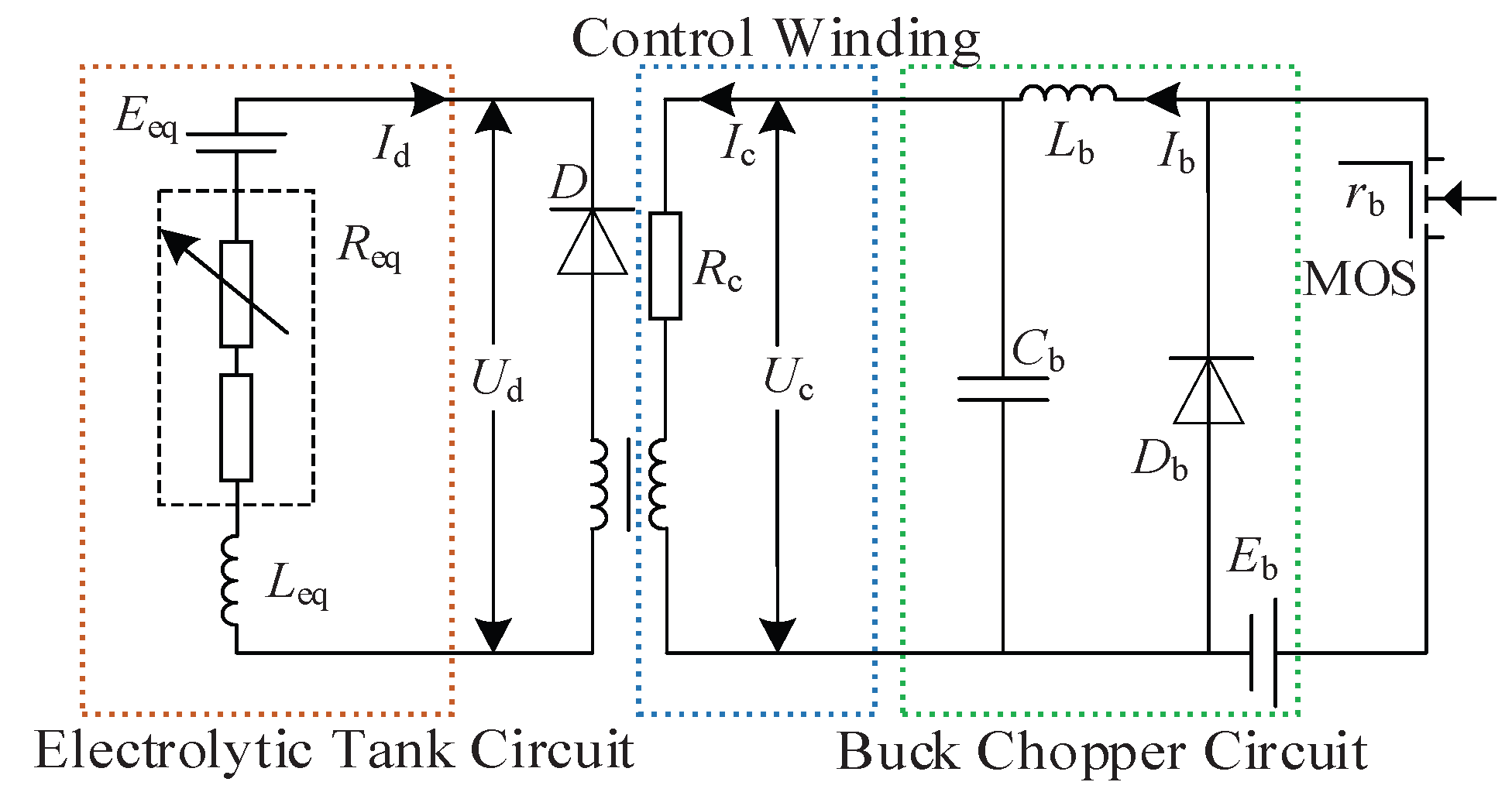
Figure 5.
Control flow chart of electrochemical energy storage participating in secondary frequency modulation.
Figure 5.
Control flow chart of electrochemical energy storage participating in secondary frequency modulation.
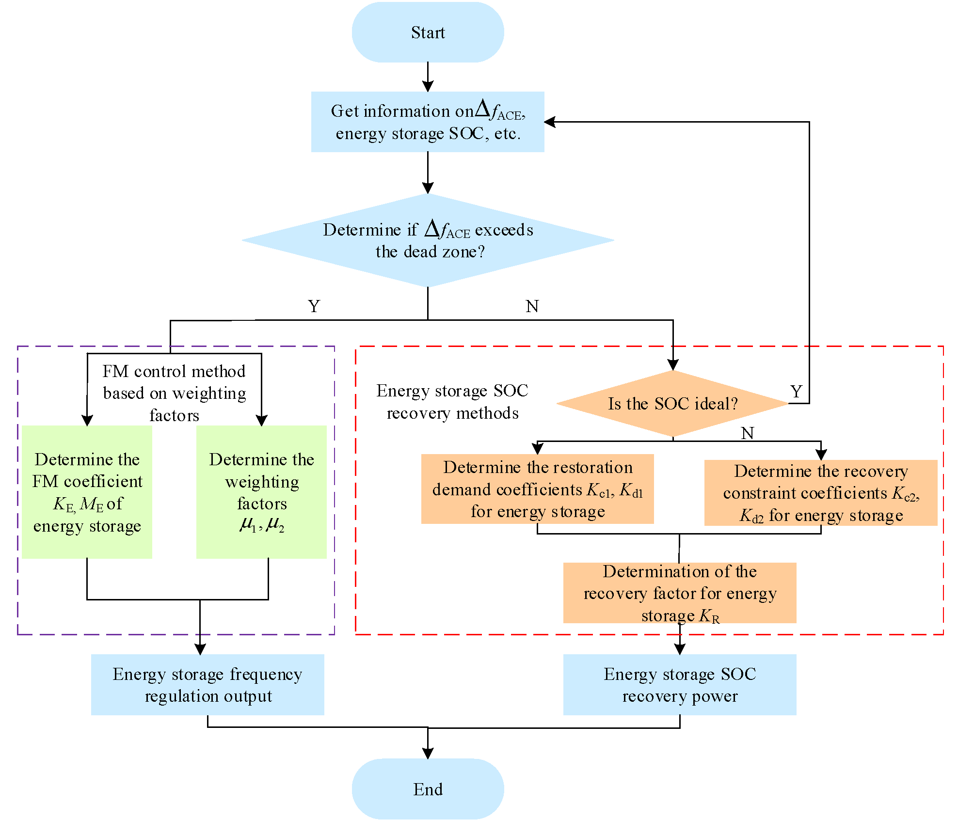
Figure 7.
Adaptive adjustment of weight factors based on fuzzy control.
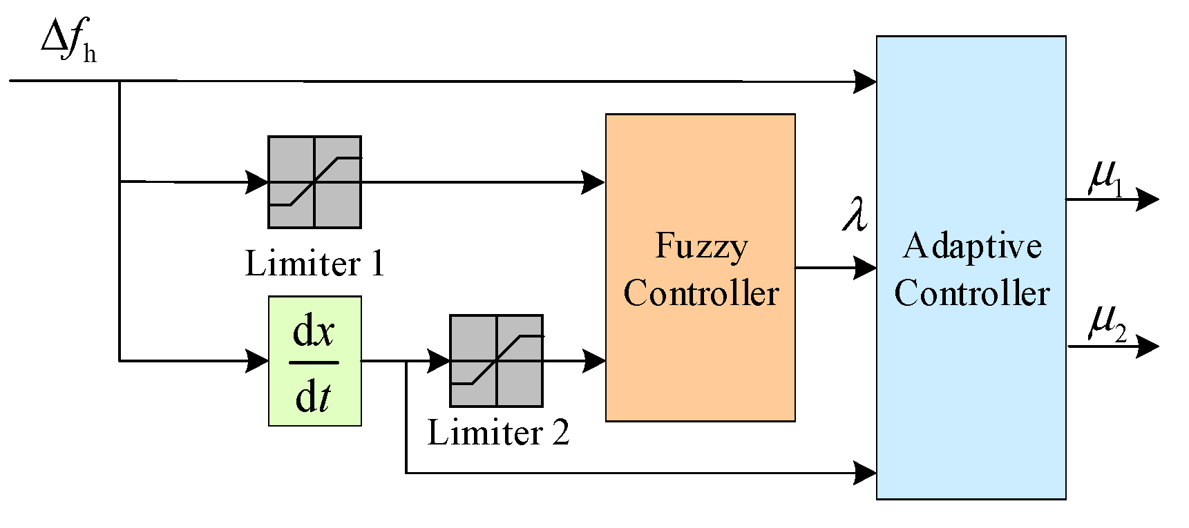
Figure 10.
Diagram of ACE interval division.
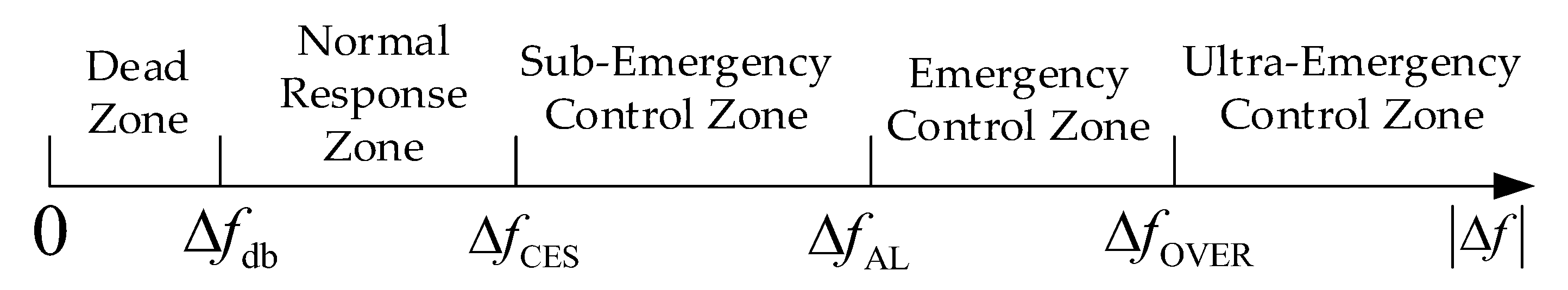
Figure 12.
Continuous disturbance of the load curve
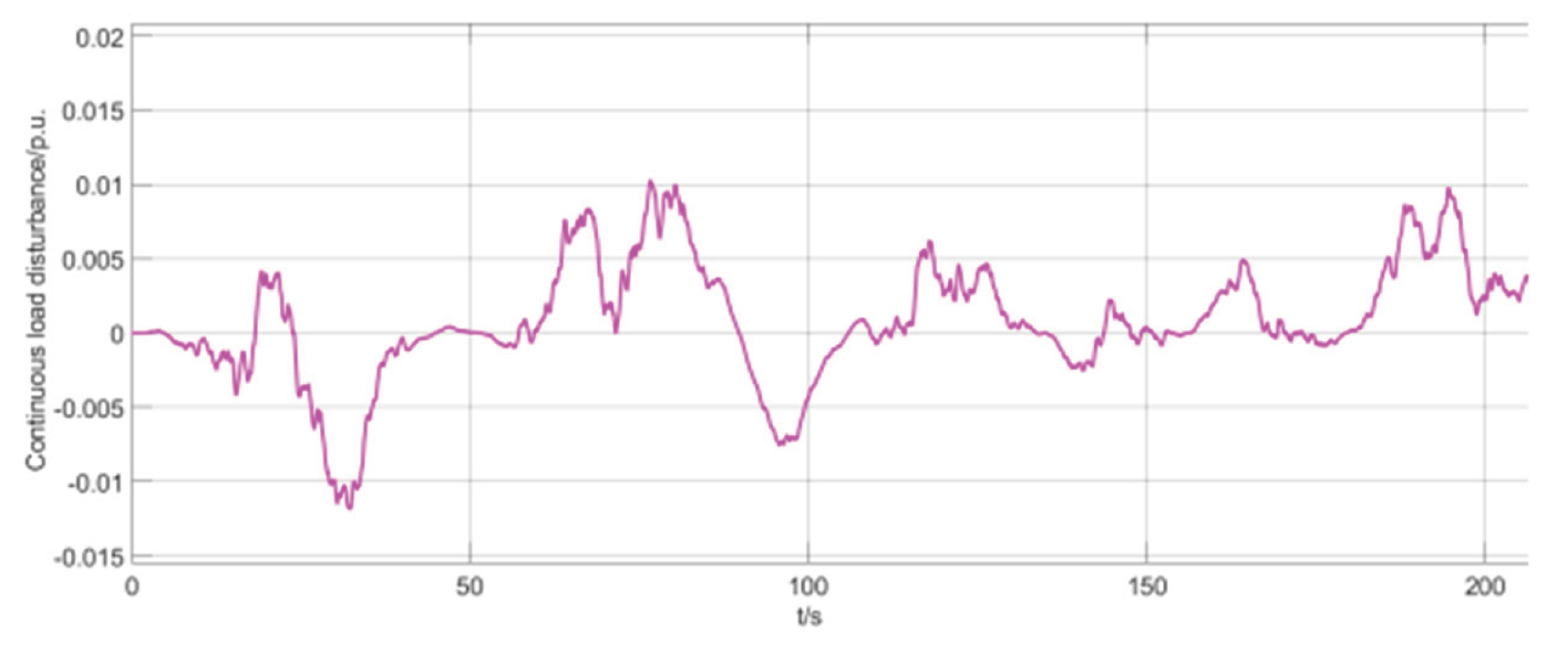
Figure 13.
System frequency change curve
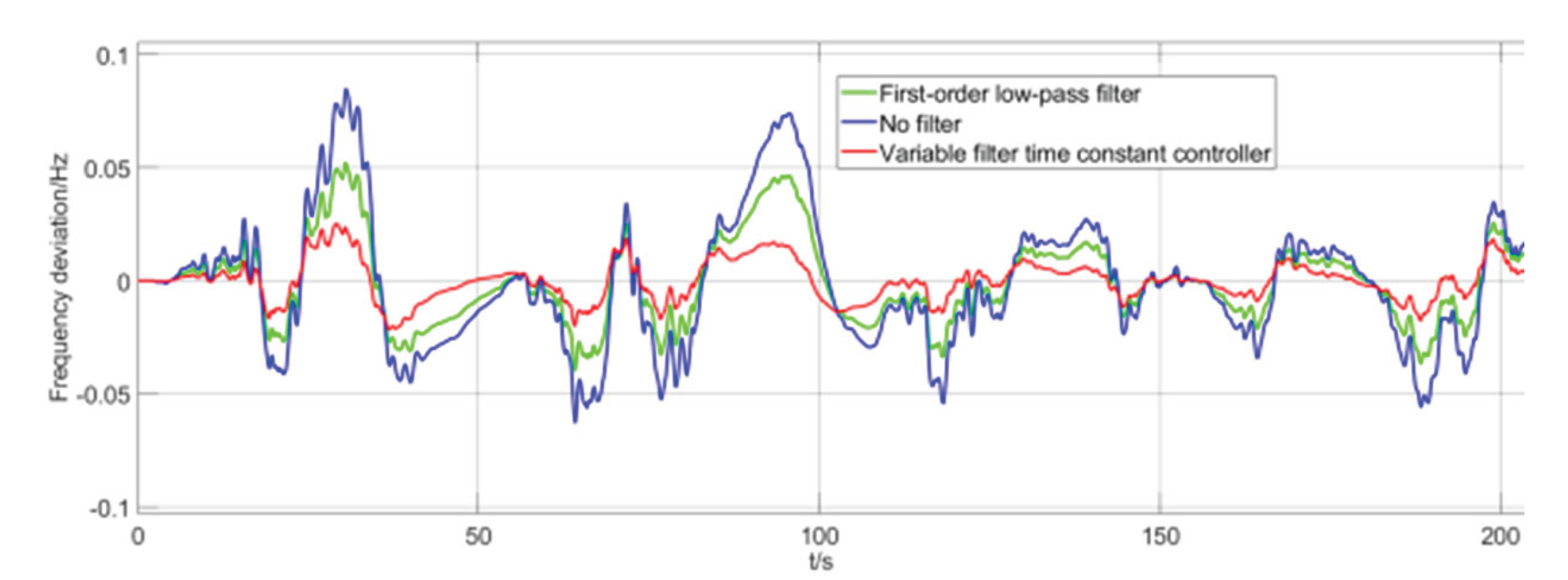
Figure 14.
Frequency deviation, output of electrochemical energy storage system and SOC change curve under step disturbance.
Figure 14.
Frequency deviation, output of electrochemical energy storage system and SOC change curve under step disturbance.
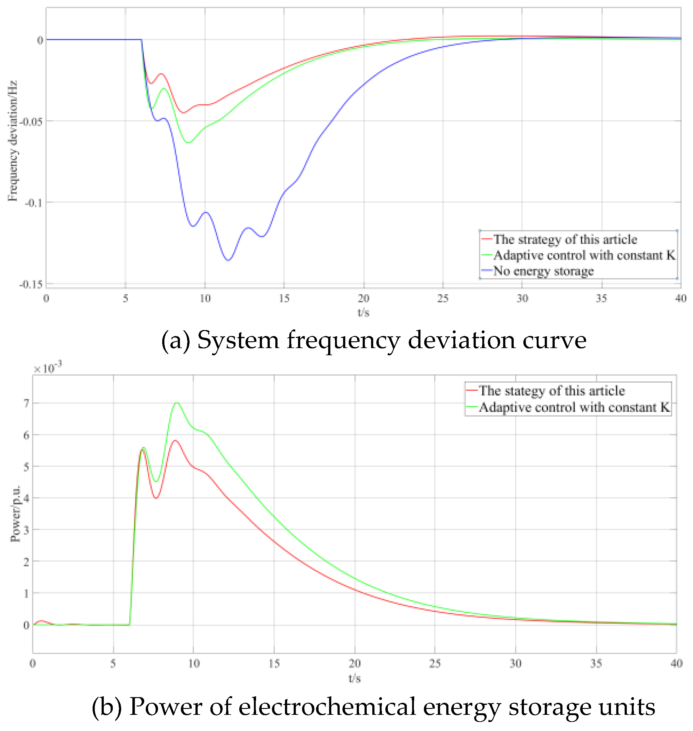
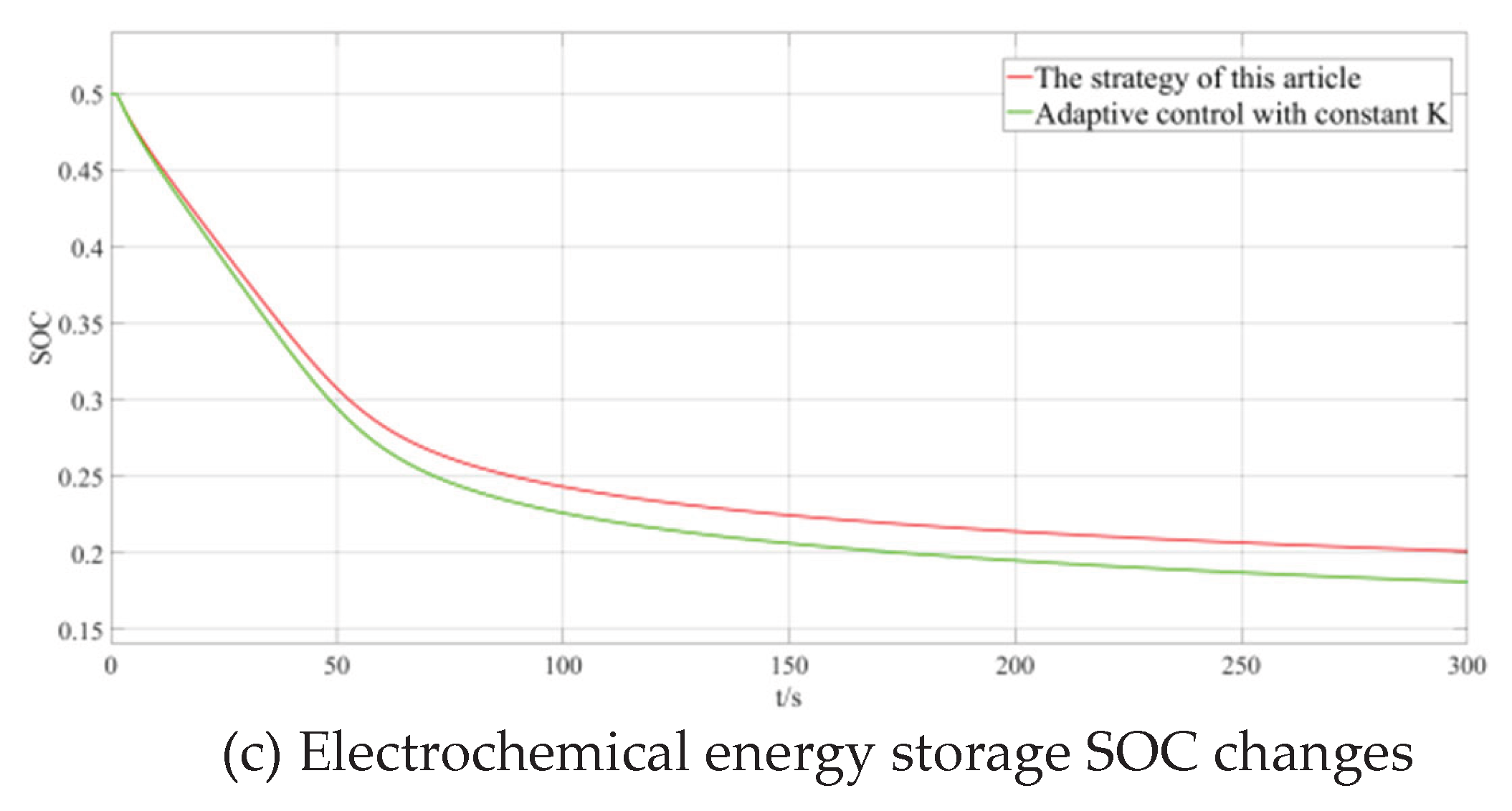
Figure 15.
Simulation results under step disturbance.
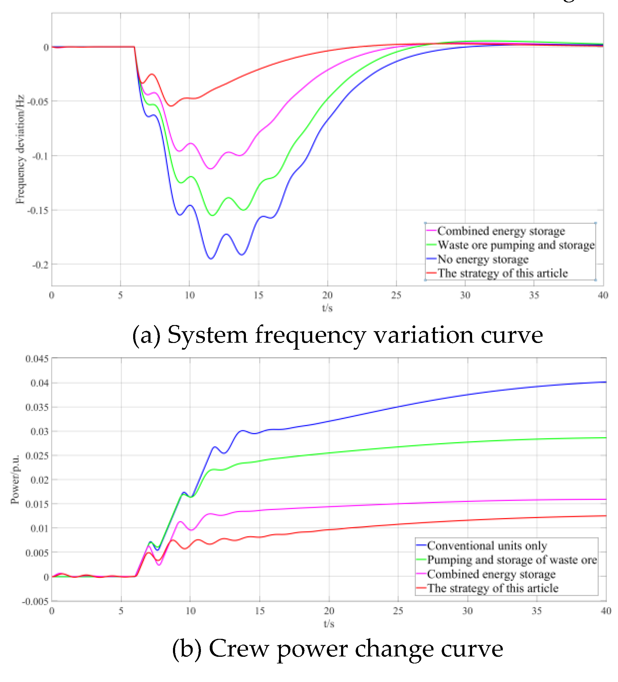
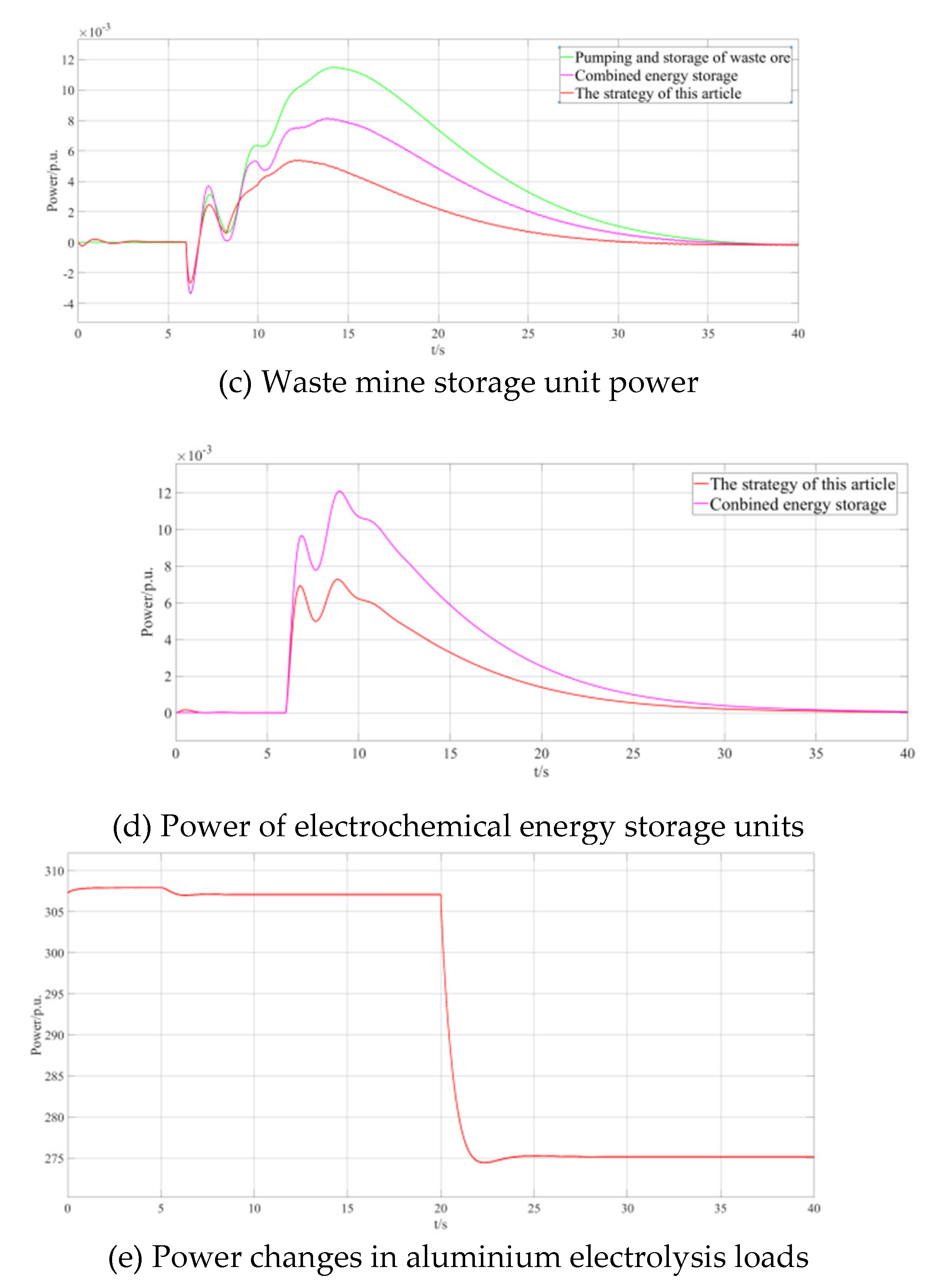
Table 2.
Adaptive selection of weight factor.
| d∆fh | ∆fh | |
| ≤0 | >0 | |
| ≤0 | λ | -λ |
| >0 | -λ | λ |
Disclaimer/Publisher’s Note: The statements, opinions and data contained in all publications are solely those of the individual author(s) and contributor(s) and not of MDPI and/or the editor(s). MDPI and/or the editor(s) disclaim responsibility for any injury to people or property resulting from any ideas, methods, instructions or products referred to in the content. |
© 2025 by the authors. Licensee MDPI, Basel, Switzerland. This article is an open access article distributed under the terms and conditions of the Creative Commons Attribution (CC BY) license (http://creativecommons.org/licenses/by/4.0/).
Copyright: This open access article is published under a Creative Commons CC BY 4.0 license, which permit the free download, distribution, and reuse, provided that the author and preprint are cited in any reuse.


