
Submitted:
10 December 2025
Posted:
11 December 2025
You are already at the latest version
Abstract
Three different Gas Tungsten Arc Welding methods – DC single-electrode, DC double-electrode, and PC double-electrode – were analyzed using SS304 steel as the base material. Numerical models were developed to simulate the arc plasmas and calculate heat flux, current density, and wall shear stress on the surface of the workpiece. These data served as input for simulating the weld pools across all three configurations. Experimental validation showed a good agreement with the numerical results. In the double-electrode setup, electromagnetic interaction caused the arcs to deflect, which resulting an 8% reduction in the maximum heat flux and a 4% decrease in the maximum current density. Marangoni stress had a notable effect on the weld pool shape, creating a w-shaped stationary pool with the single-electrode setup, whereas the pool reached its greatest depth with the stationary double-electrode configuration. With the moving weld pool, the DC double-electrode created a pool that was 41% deeper and 25% wider compared to the DC single-electrode setup. The PC double-electrode created a pool that was 40% deeper and 22% wider than the DC single-electrode configuration. The findings of the research offer guidance for enhancing different arc settings and electrode arrangements to attain the intended welding quality and performance.
Keywords:
double electrode GTAW
; tandem TIG welding
; simulation of autogenous tandem GTAW
; Pool size in twin torch GTAW
; marangoni stress in GTAW
1. Introduction
Gas Tungsten Arc Welding (GTAW) is a welding technique that employs a non-consumable tungsten electrode to produce welds. The electrode and weld pool are protected from contaminants using an inert gas, commonly argon or helium. This method is typically employed for accurate and high-grade welding in sectors that require clean and durable welds. Pulsed Current Gas Tungsten Arc Welding (PC-GTAW) is a variation of the conventional Direct Current (DC) GTAW process in which the welding current alternates between a high (peak) and a low (background) current at a controlled frequency. PC-GTAW produces better quality welds with improved strength and controlled heat input, preventing burn-through, especially in thin materials.
Double-electrode GTAW is an advanced welding process that uses two tungsten electrodes in a single welding torch or two torches arranged one behind the other along the welding direction. This configuration is also known as a Twin-Torch or Tandem GTAW. The primary objective of tandem welding is to improve productivity by increasing welding speed. Both the electrodes are independently powered and operate in the same weld pool. Usually, the leading electrode is used with high welding current to achieve sufficient penetration and add filler metal more efficiently. The trailing electrode operates with low current to manage the pool shape by maintaining it in a molten state for an extended duration, ensuring adequate time for reflow. This enhances the quality of the welding. Since both electrodes have their own power supply, they can be controlled independently, allowing for precise adjustment of the welding parameters for each arc. It is often used in automated or mechanized welding setups for applications requiring high productivity and quality, such as pipe and tube welding, cladding and overlay operations, and industries like aerospace, shipbuilding, and pressure vessel manufacturing.
Research has shown the significance of all these GTAW methods. Numerous numerical and experimental studies have been conducted to investigate various aspects of the conventional GTAW process, particularly the development of arc plasma and weld pools. Various researchers have developed numerical models to study arc behavior and have determined important parameters, including heat flux, current density, arc pressure, velocity, and gas shear stress on the surface of the workpiece. Fan and Shi investigated the arc plasma temperatures in two-dimensional [1], while Freton et al. examined them in three-dimensional [2] arc configurations. Wu and Gao [3], Due et al. [4], and Velázquez-Sánchez et al. [5] examined heat transfer and fluid flow in plasma arc columns. Sheath regions exist near the electrode and workpiece surfaces where non-equilibrium exists. They are thinly charged space layers through which current and heat transfer to the anode workpiece, and cathode tungsten electrode. A significant voltage drop occurs in these regions. Sun at al. [6], and Uhrlandt et al. [7] have investigated this phenomenon by successfully modeling the voltage drop and heat loss in the sheath regions, allowing them to predict the plasma arc more accurately. Peng et al. [8] examined this same phenomenon in micro-TIG welding process and examined heat transfer to the work part.
Extensive research exists to numerically predict the development of the weld pool in DC-GTAW influenced by different welding parameters such as the electrode tip and torch angles [9,10,11], type of shielding gas [12,13,14], arc gap [15,16], welding current [17], and welding speed [18]. In summary, increasing the electrode tip angle from 30o to 90o, produces deeper and concentric weld pools. Increasing the percentage volume of Helium, Hydrogen, or Nitrogen in Argon generates deeper weld pools. A short arc gap results in a narrow and deep molten pool. Conversely, a longer arc gap results in a wider and shallow molten pool. Increasing the welding current increases and increasing the welding speed reduces the size of the weld pool.
A significant amount of research has also explored the PC-GTAW process. Parvez et al. [19], Tradia et al. [20], and Dutra et al. [21] numerically predicted that an increase in the pulse frequency leads to a smaller pool size at frequencies between 1 Hz and 10 Hz. However, Zhang et al. [22] showed that the weld pool become deeper as the pulse frequency increases from 100 Hz to 5000 Hz. Wang et al. [23] showed similar behavior with frequencies ranging from 10 kHz to 35 kHz. Experimental studies [24,25,26] indicate that the joint strength is higher when created with PC- in comparison to DC-GTAW. For example, in reference [27], the strength of the Inconel 178 steel was found to be 7.8% higher in PC- compared to DC-GTAW. The duty cycle in PC-GTAW is also an important parameter affecting the weld pool. Duty cycle indicates the percentage of time during which the peak current is active, followed by the background current. The duty cycle affects the microstructure, strength of the weld, and pool. Wang et al. [28] found through experiments that changing the duty from 30% to 60% raised the maximum tensile shear force to 4.4 kN in the lap joint of Invar. It is obvious and demonstrated by Jiang et al. [29] that a higher duty cycle enlarges the size of the weld pool.
The double-electrode (tandem) GTAW process has been studied by numerous researchers. A comparative numerical study between the single and tandem electrode GTAW was conducted by Ogino et al. [30]. The weld spot appeared circular in single-torch configuration and elliptical in tandem setup. The tandem configuration showed a considerable decrease in plasma shear stress when compared to the single-electrode arrangement. In another numerical comparison, Wu et al. [31] found that the two arcs attract one another, resulting in their expansion. Because of the high speed, the weld pool temperatures are much lower in tandem configuration as compared to single setup and a finer weld microstructure was obtained. Kim et al. [32] developed numerical models for the tandem arcs and weld pool including the hot wire in the middle of the two electrodes. The hot wire was provided with reverse polarity which consequently reduced the attraction between the two arcs. It raised the arc pressure, force, and heat flow on the surface of the workpiece. The weld pool's depth and width were therefore increased. Ding et al. [33] also showed that the two arcs are attracted towards one another by developing a numerical model for the arc plasma with two-electrodes.
Wang et al. [34] developed unified coupled model for the arc and weld pool in double-electrode TIG welding. Arc and weld pool temperatures were calculated simultaneously. They concluded that the distribution of the current density, heat flux, and arc pressure lack rotational symmetry, which is why a Gaussian distribution cannot be used. With unequal welding currents of 80A + 120A, a significant difference in the behavior of the two arcs was observed; however, a slight difference was noted in the weld pool when compared to the one created with 100A + 100A currents. Qin et al. [35] analyzed the conventional and high-speed tandem TIG welding processes. Using double-electrode with two heat sources, the duration for liquid metal was approximately 70% longer than with single TIG welding, allowing it to flow freely and fill any depressions that could be left behind the leading electrode. In a more recent work, Schilling et al. [36] experimentally investigated the effect of tandem TIG welding parameters on the arc and weld pool shape. More inclined torches produced wider beads. Large spacing between the electrodes led to instability in the arcs. Similarly, high welding speed also resulted in instability in the process.
Numerical research on tandem TIG welding of a titanium pipe was conducted by Wu et al. [37]. In the analysis, the currents of 160A for the leading electrode and 70A for the trailing electrode were used. The positive Marangoni stress caused the molten pool to move in the reverse direction, thereby increasing its depth. An arc efficiency of 80% was determined. The efficiency of the TIG welding process was examined by Leng et al. [38]. They discovered that under identical welding conditions, the arc voltage of each electrode in tandem GTAW is slightly lower than that of the convectional method, indicating that this approach is more efficient. Kobayashi et al. [39] employed tandem GTAW to join PCLNG storage tank. It was determined that the tandem GTAW significantly shortens the completion time by employing a high welding speed. Jiang et al. [40] conducted experiments using three types of welding methods: DC-single, DC-tandem, and PC-tandem GTAW. The tensile strength of the joint produced by tandem PC-GTAW was slightly greater than in tandem DC and single torch DC-GTAW and was close to that of the base material. The weld width increased as the peak current of the leading electrode increased. A greater duty cycle resulted in deeper penetration. An increased pulse frequency improved the ratio of depth to width of the molten pool surface depression. The welding speed was increased to 3 m/min, and even at this rate, a high-quality weld was produced using tandem PC-GTAW.
The literature shows that there are limited studies exist on the comparative analysis of traditional and tandem GTAW. No research has been identified to quantitatively explore the development of arc characteristics in DC and PC double-electrode configurations. The novelty of this work is the comprehensive comparison of arc plasma properties and the weld pool formation across the three alternative methods. The findings of this study may assist scientists in the field in gaining a deeper insight into the arc and weld pool formation for improved quality and performance in arc welding.
2. Simulation Methodology
The Arc plasma
The simulation method is the same for single- and double-electrode, thus being discussed together in this section. The welding parameters used in the analyses are summarized in Table 1. As the welding electrodes are positioned perpendicular to the workpiece, the problem is planar symmetric; therefore, only half of the models were considered, as illustrated in Figure 1.
Although the arc and the workpiece domains are displayed together, they were solved individually using Ansys CFX®. The dimensions of both computational domains in Figure 1a and Figure 1b are the same. Altogether eight simulation models were developed and analyzed as summarized in Table 2. The arc models were solved in a steady state. The arc domains were defined as argon. Argon turns electrically conductive when heated to a temperature larger than 7000 K. The Arc domains were therefore initialized with a heat source to rise the temperature to that level. The heat source was subsequently removed after the argon became ionized.
The argon flow was assumed to be turbulent by applying the turbulent model. The total energy model was employed to determine heat distribution on the workpiece surface. Welding currents of 130 A and 52 A were applied to the tungsten electrodes to simulate the arc plasmas. The temperature of the tungsten electrode cannot go above 3000 K; therefore, it was set at this fixed temperature.
The argon flow was assumed to be turbulent by applying the turbulent model. The total energy model was employed to determine heat distribution on the workpiece surface. Welding currents of 130 A and 52 A were applied to the tungsten electrodes to simulate the arc plasmas. The temperature of the tungsten electrode cannot go above 3000 K; therefore, it was set at this fixed temperature.
Ansys CFX® models electric and magnetic fields by solving equations for the electric and magnetic vector potentials to calculate the current distribution on the workpiece surface. The Navier-stokes equations together with the Maxwell equations simulate the arc plasma and calculate the arc velocity, pressure, temperature, wall shear stress, current, voltage, and other properties in the arc column. In this study, heat flux, current density, and wall shear were determined on the workpiece surface and used as input to simulate the weld pool. The heat flux Q was calculated using equation (1).
Qc represents the convective heat transfer rate calculated in W/m2 at the surface of the workpiece. J is the current density in A/m2, which was also determined at the surface of the workpiece. is the work function of the steel and its value was taken as 4.3 V. Va refers to the anode fall voltage at the transition region between the arc and the workpiece and valued at 1 V. Vth is the electron thermal energy with a value of 0.58 V used in the analyses. The temperature-dependent properties of argon, including density, thermal conductivity, heat capacity, electrical conductivity, and viscosity, were taken from the work of Murphy and Tam [41].
The stationary weld pools
The stationary welds pool for single and double-electrode were simulated using a 10 mm thick, 70 mm square SS304 stainless steel plate. The thermophysical properties were taken from the handbook of properties for LMFBR Safety Analysis [42]. The whole SS304 workpiece domain was defined as liquid. A large viscosity of 1×10⁵ Pa. s was defined where the temperature was less than the melting temperature. Actual viscosity was specified where the temperature was above the melting temperature of 1723 K. The large viscosity treated the liquid domain as a solid. The variation in density of the liquid steel was assumed to be negligible, and thus, Boussinesq approximation was used to model the buoyancy-driven flow of the molten pool. Buoyancy reference temperature was set at 1723 K. The melt flow was assumed to be laminar. Marangoni stress plays a key role in defining the weld pool shape of SS304 steel particularly in the presence of high weight percent of sulfur. Later in the discussion, we will observe the effect of Marangoni stress, which is notably important in this study. The Marangoni stress was modeled according to equation (2) and (3).
Mx and My represent the Marangoni convections in the x-y plane on the workpiece surface. is the surface tension gradient shown in Figure 2. The data was taken from the work of Sahoo et al. [43], corresponding to 0.03 wt.% of sulfur; however, the critical temperature was adjusted to 2700 K to match with the “w-shape” experimental weld pool observed in this research. Additional details on the experimental weld pool shape are available in section 4. and were evaluated during the simulation run, and Mx and My were determined.
The Marangoni stress, combined with the wall shear stress, was used to simulate the weld pools. The weld spots were made in 2.0 s. The analyses did not consider the depression of the liquid pool, and the surface was treated as flat.
The moving weld pools
To simulate the moving weld pool with a single-electrode, the parameters: heat flux, current density, and wall shear stress derived from the single-electrode arc analysis were applied to the workpiece for 0.025 s, before advancing to next point at 0.25 mm in the welding direction. This process was iterated 200 times to cover the 50 mm distance. The weld started at the position wo and finished at wf, as shown in Figure 1a.
In the case of double-electrode DC GTAW, both the leading and trailing electrodes had the same current of 130 A. The two electrodes are 9 mm apart. The parameters obtained from the double-electrode arc analysis were used the same way as discussed above. In double-electrode PC GTAW, the leading electrode was held at a current of 130 A throughout, while the trailing electrode fluctuated between 130 A and 52 A at 1 Hz. The 52 A current was selected as 40% of the peak current. The parameters calculated using the peak and background currents were applied. The process was repeated 20 times using the peak parameters, then another 20 times using the background parameters to ensure 1 Hz frequency. The frequency cycle was repeated 5 times to cover the 50 mm weld length.
3. Boundary Conditions
The boundaries are defined by letters in Figure 1a showing three domains: electrode(s), arc, and workpiece. A General Grid Interface was defined between the interface areas of all three domains with conservative fluxes. Boundary g was defined as an interface between the arc and the workpiece during the arc simulation. The same boundary g was defined as a no slip wall during the weld pool simulation and heat flux, current density, Marangoni stress, and wall shear stress were applied to it. The remaining boundary conditions are given in Table 3.
4. Model Validation
The single-electrode arc model was validated using earlier data of Parvez et al. [44]. The welding conditions were the same in both studies. The isotherms presented in Figure 3 found almost similar regarding their distribution and temperature values, which shows the validity of the arc model. The single-electrode weld pool model was validated through experiments. The experiments were conducted with the same welding conditions using SS304 stainless steel plate. Welding spots were made in 2.0 s, and the specimens were cut using a wire-cut machine. A w-shaped weld pool was found after etching as shown in Figure 4b.
Although we did not perform a chemical composition test on the workpiece material to determine the precise sulfur content, the w-shape weld pool indicates the presence of a critical temperature at which the surface tension gradient changes from positive to negative. In this analysis, we therefore used the surface tension gradient which changes from positive to negative as illustrated in Figure 2. It enabled us to achieve a more realistic weld pool shape shown in Figure 4a compared to Figure 4b.
The width and depth of the numerical pool are 6.0 and 1.5 mm, whereas the width and depth of the experimental pool are 5.0 mm and 1.3 mm, respectively. The numerical model predicted the weld pool to be slightly bigger than the experimental one; however, the general trend remains consistent. As we are performing a comparative analysis, this discrepancy will not influence the findings of the study.
The velocity vectors in Figure 5 are observable in both inward and outward directions across the surface of the molten pool. The inward velocity vectors resulted from the positive surface tension gradient. The direction changed outward when the surface tension gradient became negative at a temperature above 2700 K. A w-shaped weld pool was created where the opposing vectors converged and pushed down to deepen the pool at that location. This trend resembles the results investigated by Xu at al. [45], thereby confirming the numerical model. This same model was then modified, and various investigations were performed in this research.
5. Results and Discussion
The arc plasma
The arc plasma was simulated in a steady state with both single and double-electrode configurations. The objective was to determine the heat flux, current density, and wall shear on the workpiece surface and use them to simulate the weld pool. The arc column with a single-electrode is shown in Figure 3a. The arc columns with double-electrode are illustrated in Figure 6, which shows a typical arc deflection caused by electromagnetic interaction. Because the direction of the current flow was the same in both arcs, an electromagnetic force was produced that attracted the arcs towards each other. This arc attraction (or deflection) is shown in Figure 6a. The arc deflection diminishes when the welding current reduces [46]. This effect can be seen in Figure 6b. The simulation data of Figure 6a were used to model the weld pool with DC, whereas the data of Figure 6b was employed to model the weld pool with PC GTAW.
The heat flux on the workpiece surface is illustrated in Figure 7 which was calculated using equation (1). A peak heat flux of 54.9×10⁶ W/m2 was recorded using a single-electrode, as shown in Figure 7a. Figure 7b shows the same distribution with a double-electrode setup using a welding current of 130 A on both the leading and trailing electrodes. The heat flux was determined to be 50.5×10⁶ W/m2 which is lower. This lower heat flux was a result of the arc deflection, which slightly increased the gap between the arc peak and the workpiece surface. Because the arc deflection was minimal for 130 and 52 A current applications, this decrease was consequently minor, measured as 53.7×10⁶ W/m2 generated by the leading electrode, as illustrated in Figure 7c. The trailing electrode produced a maximum heat flux of 24.7×10⁶ W/m2.
Figure 8 shows the current density distribution on the workpiece surface in all three cases. The current density is used to generate the electromagnetic force within the molten pool, pushing it downwards, which subsequently enhances the depth of the weld pool [47,48]. In this study, we did not examine the individual impact of the EM force. A symmetrical distribution of the current density was observed in the single-electrode configuration, reaching a peak of 6.9×10⁶ A/m2, as illustrated in Figure 8a. The peak value reduced to 6.6×10⁶ A/m2 in double-electrode setup (Figure 8b) because of the arc deflection. In Figure 8c, the maximum current densities were 6.8×10⁶ A/m2 and 4.0×10⁶ A/m2 measured with 130 A and 52 A welding currents, respectively.
The distribution of the wall shear stress on the workpiece surface is shown in Figure 9. The plasma arc layer moving over the molten pool creates wall shear stress. This contributes to an increase in the width of the weld pool investigated by Wang et al. [49], and Stadler et al. [50]. We did not examine this specifically; instead, we added it to the Marangoni stress to simulate the weld pool.
A maximum wall shear stress of 2.7 Pa was found with one electrode, whereas it was observed as 4.1 Pa with double-electrode at the same welding current of 130 A, as illustrated in Figure 9a and Figure 9b. This increase resulted from the arcs being attracted towards each other. Therefore, the wall shear is maximum inside the two electrodes. Figure 9c represents the wall shear on the workpiece surface at currents of 130 and 52 A. The 130 A current generated a maximum wall shear of 3.3 Pa, whereas the 52 A current resulted in an insignificant shear stress of 0.003 Pa. The figure does not depict contours at the specified scale.
The stationary weld pools
Section 4 describes a stationary weld pool with a single-electrode configuration. This section discusses the stationary weld pool formed using a double electrode. Figure 10 shows the progression of the pool over time with a peak welding current of 130 A applied to each electrode. E1 and E2 denote the centers of the leading and trailing electrodes, respectively, which are 9 mm apart from each other. Point o represents the central distance between the two electrodes.
The pools began to grow beneath the corresponding electrodes, and the same w-shaped pool was observed. Because of the Marangoni convection, the velocity vectors were directed inward on the surfaces of both molten pools. The pools started to merge after 1.0 s. As the critical temperature reached, the velocity vectors changed direction, and the opposing vectors converged at o. The direction shifted downward, resulting in a deeper pool as illustrated in the Figure at time 2.0 s. The small arrows in each figure clarify this phenomenon. The maximum pool depth and width were 2.9 mm and 13.6 mm, respectively.
Figure 11 shows the development of the pool with welding currents of 130 A and 52 A applied to the leading and trailing electrodes, respectively. It is important to mention that the 52 A only maintained the arc to glow during the background current cycle in PC-GTAW. It produced a small weld pool that was 1.9 mm wide, and 0.2 mm deep after 2.0 s. The 130 A current created a 6.0 mm wide and 1.5 mm deep weld pool, which was the same size as that produced with the single-electrode, as depicted in Figure 4a. However, the shape is slightly different because one side of the pool acquired a sudden depth because of the heat from the trailing electrode.
The moving weld pools
This section addresses the development of the weld pool in DC single, DC double, and PC double-electrode autogenous GTAW process. The weld pool moved 50 mm (from wo to wf in Figure 1a) at a speed of 10 mm/s. The remaining welding parameters were the same as those mentioned in Table 1. Figure 12a displays a weld pool at 4.0 s that was fully developed after 1.0 s and maintained its shape and size until the process was completed. A maximum pool temperature of 2800 K was recorded. Figure 12b shows the weld pool formed using DC double-electrode configuration. Although the currents were the same on both electrodes, the trailing pool was larger because of the heat generated by the leading electrode. In this case, the weld pool developed completely in 2.0 s, reaching a peak temperature of 3200 K. The pools did not fully merge at a welding speed of 10 mm/s. This shows that increasing the welding speed causes the two pools to move apart. Reducing the speed combine the two pools into a single pool.
Figure 12c illustrates the weld pool at 4.0 s generated using the PC double-electrode configuration. The background current was active at that time. The respective electrodes created separate weld pools. Owing to the background current on the trailing electrode, the depth and width of the pool were less than those of the leading pool. Shortly thereafter, the trailing electrode activated the peak current, the pool size increased, and merged with the leading pool, as shown in Figure 12d. A maximum pool temperature of 3200 K was found which is the same as that in the case of the DC double-electrode setup. The leading pool preserved its depth and width throughout the pulse cycles.
Figure 13 shows a comparison of the maximum pool depth and width for the same three electrode configurations. In the case of double-electrode setups, the sizes of the leading pools are the same, whereas the dimensions of the trailing pools differ and are larger than those of the leading pools. The measured pool depths were 1.0 mm, 1.7 mm, and 1.4 mm for the DC single, DC double, and PC double-electrode, respectively, indicating that the DC double configuration produced the deepest pool among the three. Correspondingly, the maximum pool widths were 2.1, 2.8, and 2.7 mm, respectively, with the DC double-electrode achieving the greatest width. Note that Figure 13 illustrates only half of the pool width due to the symmetry of the pool shape, which implies that the actual full widths are twice the values shown.
These results show that the DC double-electrode configuration generates the largest molten pool size, both in terms of depth and width, compared to the other configurations simulated. Employing a double-electrode with a direct current source enhances the energy input and heat distribution, thereby increasing the pool dimensions. The slightly smaller pool size observed with the PC double-electrode reflects differences in the power delivery and electrode arrangement. Understanding these variations is critical for optimizing the welding or melting process parameters to achieve the desired pool characteristics for specific material-joining applications.
6. Conclusions
The study comprehensively investigated the behavior of arc plasma and weld pool dynamics in single and double-electrode configurations in autogenous GTAW processes. The simulations of the arc plasma reveal that electromagnetic interactions in double-electrode setups cause arc deflection. As a result of the arc deflection, the maximum value of the heat flux in the DC double-electrode configuration reduced by 8% compared to that in the DC single-electrode setup. This reduction was 4% in terms of current density. The wall shear stress was found to be the lowest with the DC single and the highest in the DC double-electrode arrangement.
Stationary weld pool simulations show that the double-electrode method produced unique pool shapes resulting from Marangoni convection and thermal interactions between the leading and trailing pools. In the DC single-electrode configuration, the pool was w-shaped and was wider and deeper in the DC double-electrode configuration. In comparing the stationary pool depths, the depth measured 1.5 mm in the DC single-electrode setup and 2.9 mm in the DC double-electrode setup, indicating that the weld pool was 48% deeper in the double-electrode setup.
The moving weld pool simulations show that the DC double-electrode configuration produced the largest molten pool. The DC double-electrode configuration resulted in a larger trailing pool, whereas the PC double-electrode configuration generated a smaller trailing pool due to the lower background current. The width and depth were 25% and 41% larger, respectively, than those observed in the DC single-electrode configuration. The PC double-electrode produced 22% wider and 40% deeper pools than the DC single-electrode setup.
The findings highlight the use of the double-electrode configuration in GTAW and its effect on the weld pool size, shape, and thermal characteristics. The enhanced understanding of arc interactions and weld pool dynamics under different electrode and welding current setups provides valuable insights for optimizing welding parameters to achieve desired weld quality and performance in arc welding.
Funding
This research received no external funding
Data Availability Statement
The original contributions presented in this study are included in the article. Further inquiries can be directed to the corresponding author.
Acknowledgements
The author is grateful to the Department of Mechanical Engineering, College of Engineering, King Sud University, Saudi Arabia, for providing computational resources.
Conflicts of Interest
The author declares no conflicts of interest
References
- Fan, H.G.; Shi, Y.W. Numerical Simulation of the Arc Pressure in Gas Tungsten Arc Welding. Journal of Materials Processing Technology 1996, 61, 302–308. [Google Scholar] [CrossRef]
- Freton, P.; Gonzalez, J.J.; Gleizes, A. Comparison between a Two- and a Three-Dimensional Arc Plasma Configuration. J. Phys. D: Appl. Phys. 2000, 33, 2442–2452. [Google Scholar] [CrossRef]
- Wu, C.S.; Gao, J.Q. Analysis of the Heat Flux Distribution at the Anode of a TIG Welding Arc. Computational Materials Science 2002, 24, 323–327. [Google Scholar] [CrossRef]
- Du, H.; Wei, Y.; Wang, W.; Lin, W.; Fan, D. Numerical Simulation of Temperature and Fluid in GTAW-Arc under Changing Process Conditions. Journal of Materials Processing Technology 2009, 209, 3752–3765. [Google Scholar] [CrossRef]
- Velázquez-Sánchez, A.; Delgado-Álvarez, A.; Méndez, P.F.; Murphy, A.B.; Ramírez-Argáez, M.A. Dominant Heat Transfer Mechanisms in the GTAW Plasma Arc Column. Plasma Chem Plasma Process 2021, 41, 1497–1515. [Google Scholar] [CrossRef]
- Sun, J.-H.; Sun, S.-R.; Niu, C.; Wang, H.-X. Non-Equilibrium Modeling on the Plasma–Electrode Interaction in an Argon DC Plasma Torch. J. Phys. D: Appl. Phys. 2021, 54, 465202. [Google Scholar] [CrossRef]
- Uhrlandt, D.; Baeva, M.; Pipa, A.V.; Kozakov, R.; Gött, G. Cathode Fall Voltage of TIG Arcs from a Non-Equilibrium Arc Model. Weld World 2015, 59, 127–135. [Google Scholar] [CrossRef]
- Pang, S.; Cao, B.; Wang, Y. Numerical Analysis of Low-Current Arc Characteristics in Micro-TIG Welding. Journal of Manufacturing Processes 2023, 105, 246–259. [Google Scholar] [CrossRef]
- Goodarzi, M.; Choo, R.; Takasu, T.; Toguri, J.M. The Effect of the Cathode Tip Angle on the Gas Tungsten Arc Welding Arc and Weld Pool: II. The Mathematical Model for the Weld Pool. J. Phys. D: Appl. Phys. 1998, 31, 569–583. [Google Scholar] [CrossRef]
- Abid, M.; Parvez, S.; Nash, D.H. Effect of Different Electrode Tip Angles with Tilted Torch in Stationary Gas Tungsten Arc Welding: A 3D Simulation. International Journal of Pressure Vessels and Piping 2013, 108–109, 51–60. [Google Scholar] [CrossRef]
- Parvez, S.; Abid, M.; Nash, D.H.; Fawad, H.; Galloway, A. Effect of Torch Angle on Arc Properties and Weld Pool Shape in Stationary GTAW. J. Eng. Mech. 2013, 139, 1268–1277. [Google Scholar] [CrossRef]
- Huang, H.-Y.; Yang, C.-W. Influence of Activating Flux and Helium Shielding Gas on an Austenitic Stainless Steel Weldment. Metall Mater Trans B 2013, 44, 730–737. [Google Scholar] [CrossRef]
- Huang, H.-Y. Argon-Hydrogen Shielding Gas Mixtures for Activating Flux-Assisted Gas Tungsten Arc Welding. Metall Mater Trans A 2010, 41, 2829–2835. [Google Scholar] [CrossRef]
- Huang, H.-Y. Effects of Shielding Gas Composition and Activating Flux on GTAW Weldments. Materials & Design 2009, 30, 2404–2409. [Google Scholar] [CrossRef]
- Jou, M. Experimental Study and Modeling of GTA Welding Process. Journal of Manufacturing Science and Engineering 2003, 125, 801–808. [Google Scholar] [CrossRef]
- Chen, D.; Cai, Y.; Luo, Y.; Wang, X.; Chi, L.; Tang, F. Measurement and Analysis on the Thermal and Mechanical Transfer Characteristics of GTA Arc Affected by Arc Length. Measurement 2020, 153, 107431. [Google Scholar] [CrossRef]
- Zhang, G.; Shi, Y.; Zhu, M.; Fan, D. Effect of Electric Parameters on Weld Pool Dynamic Behavior in GTAW. Journal of Manufacturing Processes 2022, 77, 369–379. [Google Scholar] [CrossRef]
- Coniglio, N.; Cross, C.E. Effect of Weld Travel Speed on Solidification Cracking Behavior. Part 1: Weld Metal Characteristics. Int J Adv Manuf Technol 2020, 107, 5011–5023. [Google Scholar] [CrossRef]
- Parvez, S.; El Rayes, M.; Al-Bahkali, E.; Alqosaibi, K. Numerical Investigation of the Influence of Pulse Frequency on the Weld Pool Size in Pulsed Current TIG Welding. AIP Advances 2025, 15, 015115. [Google Scholar] [CrossRef]
- Traidia, A.; Roger, F.; Guyot, E. Optimal Parameters for Pulsed Gas Tungsten Arc Welding in Partially and Fully Penetrated Weld Pools. International Journal of Thermal Sciences 2010, 49, 1197–1208. [Google Scholar] [CrossRef]
- Dutra, J.C.; Riffel, K.C.; Silva, R.H.G.E.; Ramirez, A.J. A Contribution to the Analysis of the Effects of Pulsed Current in GTAW Welding of 1-Mm-Thick AISI 304 Sheets. Metals 2023, 13, 1387. [Google Scholar] [CrossRef]
- ZHANG, G.; XU, Z.; WANG, K.; ZHU, M.; SHI, Y. Analysis of Arc and Weld Pool Characteristics in Direct Current Added-Pulsed TIG Welding Process. TRANSACTIONS OF THE CHINA WELDING INSTITUTION 2022, 43, 75–81. [Google Scholar] [CrossRef]
- Wang, Y.; Chen, M.; Wu, C. High-Frequency Pulse-Modulated Square Wave AC TIG Welding of AA6061-T6 Aluminum Alloy. Weld World 2020, 64, 1749–1762. [Google Scholar] [CrossRef]
- Yelamasetti, B.; Karuna, B.N.R.; Vishnu Vardhan, T.; Dasore, A.; Saxena, K.K.; Faroque, F.A.; Revathi, V.; Abduvalieva, D. Mechanical and Micro-Structural Studies of Pulsed and Constant Current TIG Weldments of Super Duplex Stainless Steels and Austenitic Stainless Steels. High Temperature Materials and Processes 2024, 43, 20240003. [Google Scholar] [CrossRef]
- Wang, Q.; Tong, X.; Wu, G.; Zhan, J.; Qi, F.; Zhang, L.; Liu, W. Microstructure and Strengthening Mechanism of TIG Welded Joints of a Mg-Nd-Gd Alloy: Effects of Heat Input and Pulse Current. Materials Science and Engineering: A 2023, 869, 144816. [Google Scholar] [CrossRef]
- Sabzi, M.; Mousavi Anijdan, S.H.; Eivani, A.R.; Park, N.; Jafarian, H.R. The Effect of Pulse Current Changes in PCGTAW on Microstructural Evolution, Drastic Improvement in Mechanical Properties, and Fracture Mode of Dissimilar Welded Joint of AISI 316L-AISI 310S Stainless Steels. Materials Science and Engineering: A 2021, 823, 141700. [Google Scholar] [CrossRef]
- Yelamasetti, B.; Devi, B.T.L.; Saxena, K.K.; Sonia, P.; Vardhan, T.V.; Sree, N.S.; Khubnani, R.; Abdo, H.S.; Alnaser, I. Mechanical Characterization and Microstructural Evolution of Inconel 718 and SS316L TIG Weldments at High Temperatures. Journal of Materials Research and Technology 2024, 32, 196–207. [Google Scholar] [CrossRef]
- Wang, H.; Hu, S.; Shen, J.; Li, D.; Lu, J. Effect of Duty Cycle on Microstructure and Mechanical Properties of Pulsed GTAW Lap Joint of Invar. Journal of Materials Processing Technology 2017, 243, 481–488. [Google Scholar] [CrossRef]
- Jiang, Y.; Wu, J.; Zhou, C.; Han, Q.; Hua, C. Study on Pulsed Gas Tungsten Arc Lap Welding Techniques for 304L Austenitic Stainless Steel. Crystals 2024, 14, 715. [Google Scholar] [CrossRef]
- Ogino, Y.; Hirata, Y.; Kawata, J.; Nomura, K. Numerical Analysis of Arc Plasma and Weld Pool Formation by a Tandem TIG Arc. In Weld World; 2013. [Google Scholar] [CrossRef]
- Wu, D.; Huang, J.; Kong, L.; Hua, X.; Wang, M. Coupled Mechanisms of Arc, Weld Pool and Weld Microstructures in High Speed Tandem TIG Welding. International Journal of Heat and Mass Transfer 2020, 154, 119641. [Google Scholar] [CrossRef]
- Kim, J.; Lee, J.; Lee, S.H. Effect of Reverse-Polarity Hot Wire on the Tandem Arc Welding Process. Engineering Science and Technology, an International Journal 2022, 36, 101168. [Google Scholar] [CrossRef]
- Ding, X.; Li, H.; Yang, L.; Gao, Y.; Wei, H. Numerical Analysis of Arc Characteristics in Two-Electrode GTAW. Int J Adv Manuf Technol 2014, 70, 1867–1874. [Google Scholar] [CrossRef]
- Wang, X.; Fan, D.; Huang, J.; Huang, Y. A Unified Model of Coupled Arc Plasma and Weld Pool for Double Electrodes TIG Welding. J. Phys. D: Appl. Phys. 2014, 47, 275202. [Google Scholar] [CrossRef]
- Qin, G.; Feng, C.; Ma, H. Suppression Mechanism of Weld Appearance Defects in Tandem TIG Welding by Numerical Modeling. Journal of Materials Research and Technology 2021, 14, 160–173. [Google Scholar] [CrossRef]
- Schilling, P.; Synnatzschke, P.; Ungethüm, T.; Schmale, H.C. TIG Double-Electrode Welding: Insights into Electrical and Geometric Parameter Effects on Process Stability and Seam Quality. In Weld World; 2025. [Google Scholar] [CrossRef]
- Wu, D.; Huang, J.; Kong, L.; Hua, X.; Wang, M.; Li, H.; Liu, S. Numerical Analysis of Arc and Molten Pool Behaviors in High Speed Tandem TIG Welding of Titanium Tubes. Transactions of Nonferrous Metals Society of China 2023, 33, 1768–1778. [Google Scholar] [CrossRef]
- Leng, X.-S.; Zhang, G.-J.; Wu, L. Experimental Study on Improving Welding Efficiency of Twin Electrode TIG Welding Method. Science and Technology of Welding and Joining 2006, 11, 550–554. [Google Scholar] [CrossRef]
- Kobayashi, K.; Nishimura, Y.; Iijima, T.; Ushio, M.; Tanaka, M.; Shimamura, J.; Ueno, Y.; Yamashita, M. Practical Application of High Efficiency Twin-Arc TIG Welding Method (Sedar-TIG) for Pclng Storage Tank. Weld World 2004, 48, 35–39. [Google Scholar] [CrossRef]
- JIANG, H.; QIN, G.; FENG, C.; X. MENG High-Speed Tandem Pulsed GTAW of Thin Stainless Steel Plate. WJ 2019, 98, 215–226. [Google Scholar] [CrossRef]
- Murphy, A.B.; Tam, E. Thermodynamic Properties and Transport Coefficients of Arc Lamp Plasmas: Argon, Krypton and Xenon. J. Phys. D: Appl. Phys. 2014, 47, 295202. [Google Scholar] [CrossRef]
- Leibowitz, L. Properties for LMFBR Safety Analysis; Argonne National Lab: Illinois; USA, 1976; p. 116. [Google Scholar]
- Sahoo, P.; Debroy, T.; McNallan, M.J. Surface Tension of Binary Metal—Surface Active Solute Systems under Conditions Relevant to Welding Metallurgy. Metall Trans B 1988, 19, 483–491. [Google Scholar] [CrossRef]
- Parvez, S.; Abid, M.; Nash, D.H.; Fawad, H.; Galloway, A. Effect of Torch Angle on Arc Properties and Weld Pool Shape in Stationary GTAW. J. Eng. Mech. 2013, 139, 1268–1277. [Google Scholar] [CrossRef]
- Xu, Y.L.; Dong, Z.B.; Wei, Y.H.; Yang, C.L. Marangoni Convection and Weld Shape Variation in A-TIG Welding Process. Theoretical and Applied Fracture Mechanics 2007, 48, 178–186. [Google Scholar] [CrossRef]
- Chen, D.; Chen, M.; Wu, C. Effects of Phase Difference on the Behavior of Arc and Weld Pool in Tandem P-GMAW. Journal of Materials Processing Technology 2015, 225, 45–55. [Google Scholar] [CrossRef]
- Nemchinsky, V.A. The Distribution of the Electromagnetic Force in a Welding Pool. J. Phys. D: Appl. Phys. 1996, 29, 2659–2663. [Google Scholar] [CrossRef]
- Tanaka, M.; Lowke, J.J. Predictions of Weld Pool Profiles Using Plasma Physics. J. Phys. D: Appl. Phys. 2007, 40, R1–R23. [Google Scholar] [CrossRef]
- Wang, X.; Fan, D.; Huang, J.; Huang, Y. Numerical Simulation of Arc Plasma and Weld Pool in Double Electrodes Tungsten Inert Gas Welding. International Journal of Heat and Mass Transfer 2015, 85, 924–934. [Google Scholar] [CrossRef]
- Stadler, M.; Freton, P.; Gonzalez, J.-J. Influence of Welding Parameters on the Weld Pool Dimensions and Shape in a TIG Configuration. Applied Sciences 2017, 7, 373. [Google Scholar] [CrossRef]
Figure 1.
Computation domain (a) single-electrode (b) double-electrode: showing mesh
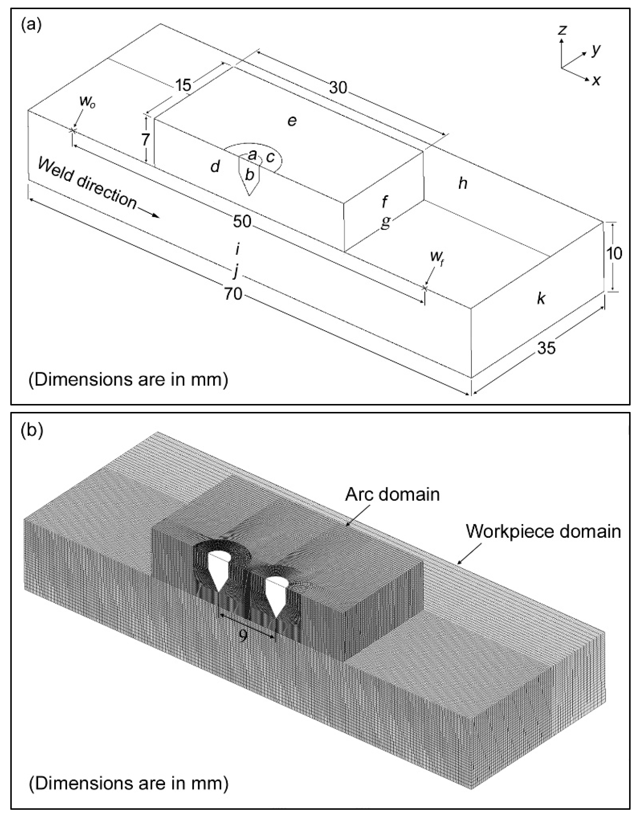
Figure 2.
Surface tension gradient used in the analyses.
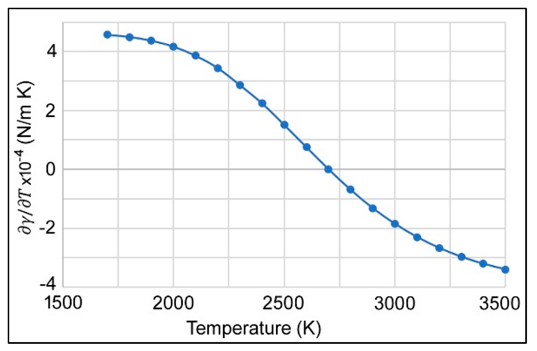
Figure 3.
Comparison of the arc temperatures (a) present study (b) Parvez et al. [44]
Figure 3.
Comparison of the arc temperatures (a) present study (b) Parvez et al. [44]
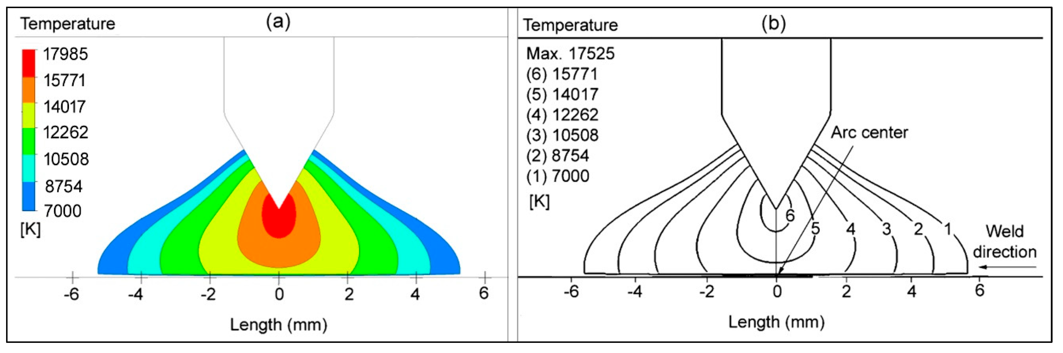
Figure 4.
Comparison of the weld pool (a) Numerical (b) Experimental
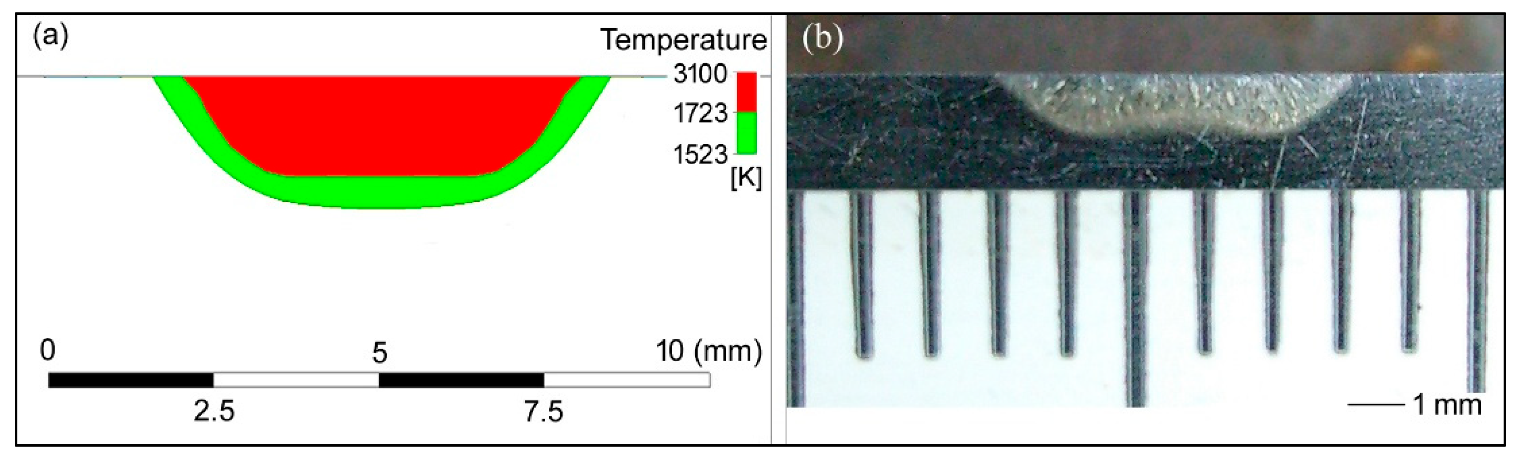
Figure 5.
Velocity vectors in the molten pool.
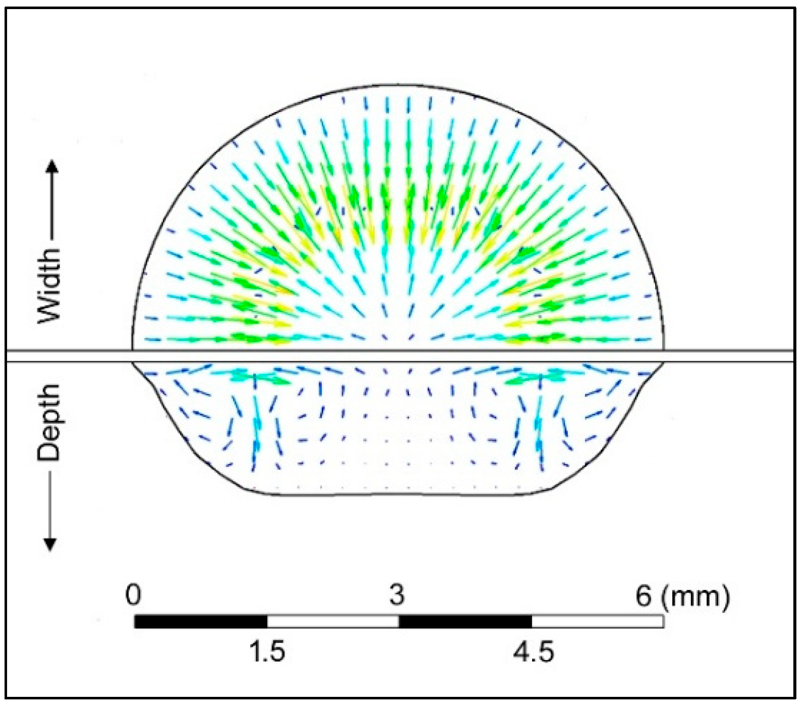
Figure 6.
Plasma arc temperatures at currents (a) 130A+130A (b) 52A+130A
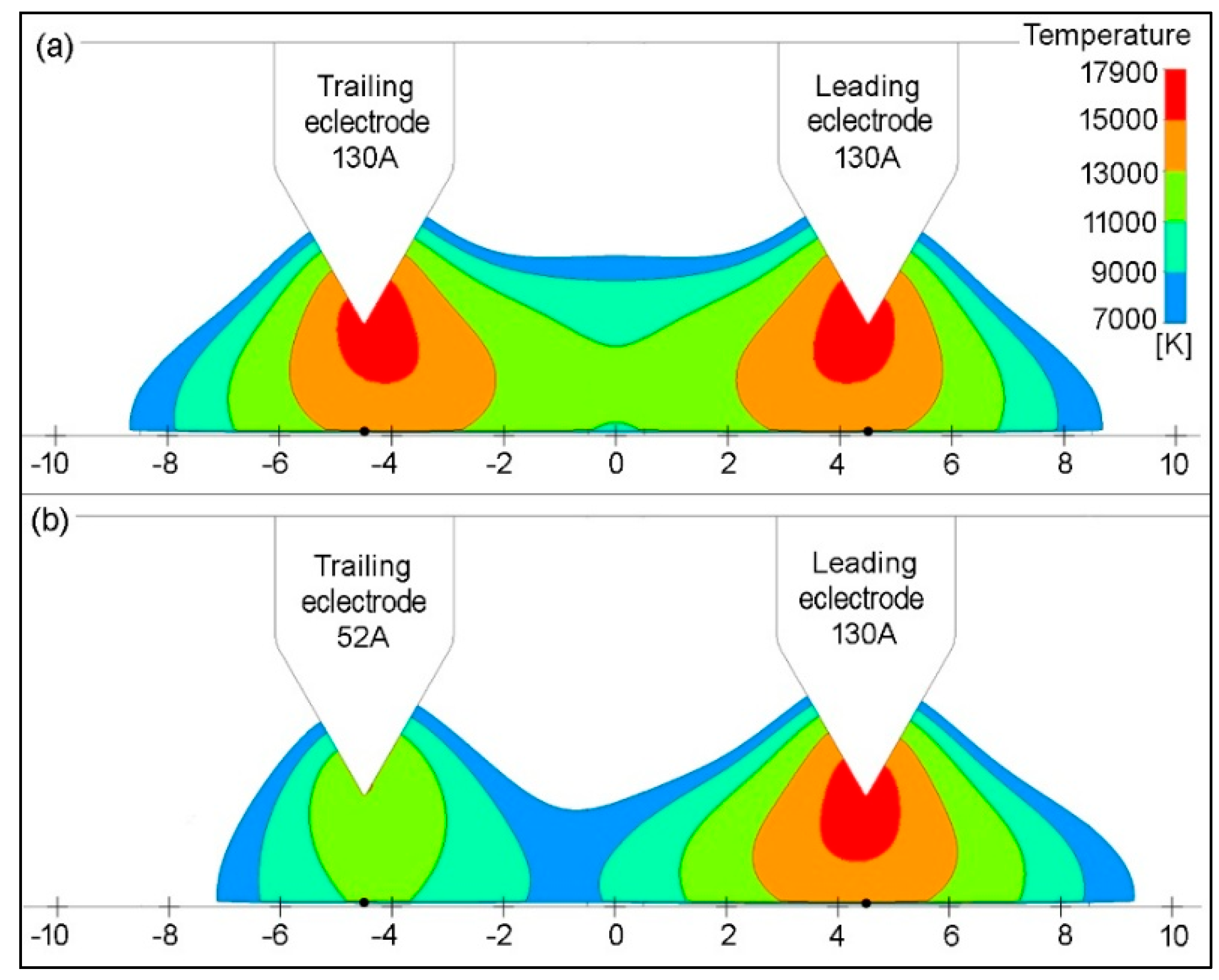
Figure 7.
Heat flux on the workpiece surface with (a) Single-electrode (b) Double-electrode peak current (c) Double-electrode background current.
Figure 7.
Heat flux on the workpiece surface with (a) Single-electrode (b) Double-electrode peak current (c) Double-electrode background current.
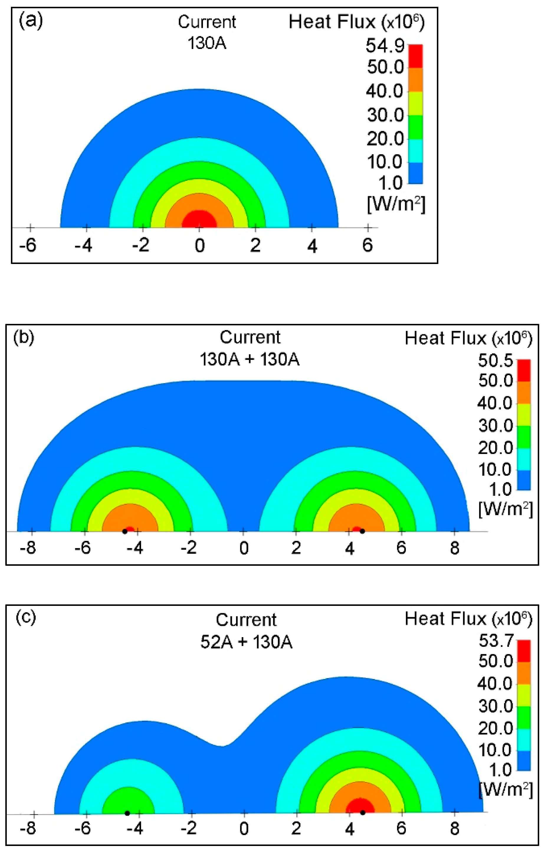
Figure 8.
Current density on the workpiece surface with (a) Single-electrode (b) Double-electrode peak current (c) Double-electrode background current
Figure 8.
Current density on the workpiece surface with (a) Single-electrode (b) Double-electrode peak current (c) Double-electrode background current
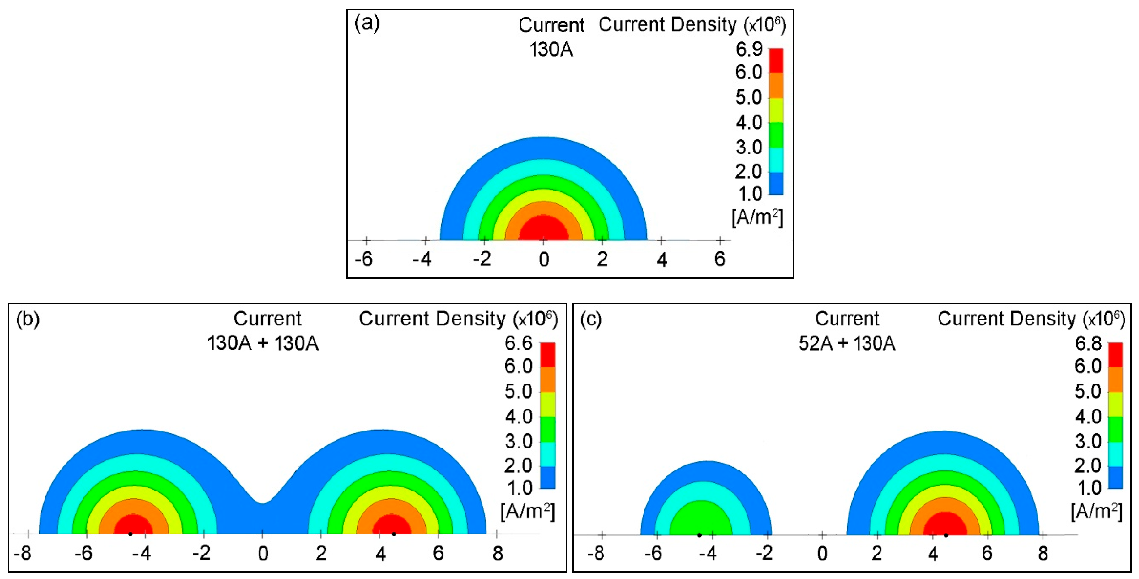
Figure 9.
Wall shear at the workpiece surface with (a) Single-electrode (b) Double-electrode peak current (c) Double-electrode background current
Figure 9.
Wall shear at the workpiece surface with (a) Single-electrode (b) Double-electrode peak current (c) Double-electrode background current
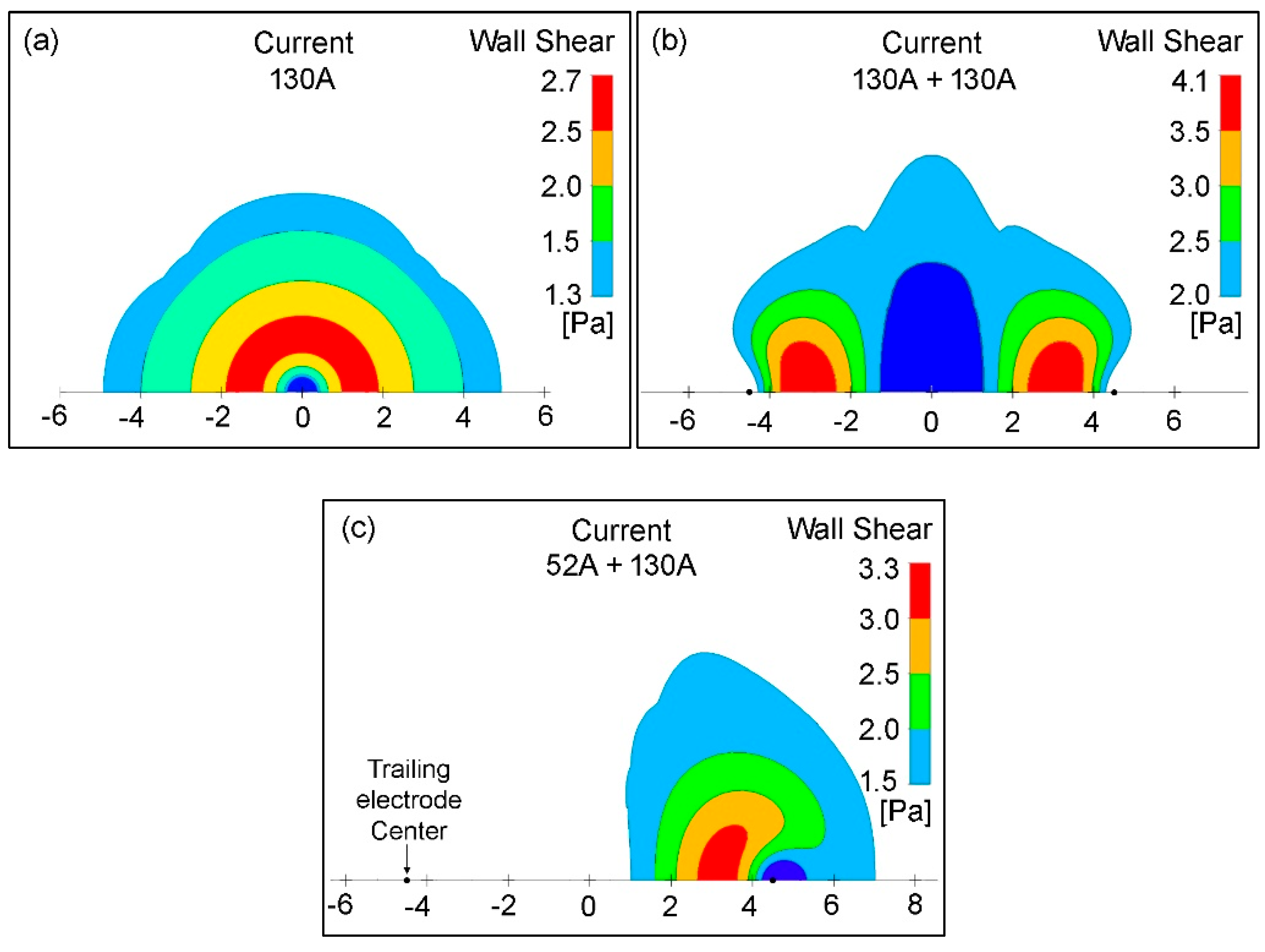
Figure 10.
Stationary weld pool development over time: Double-electrode with peak current.
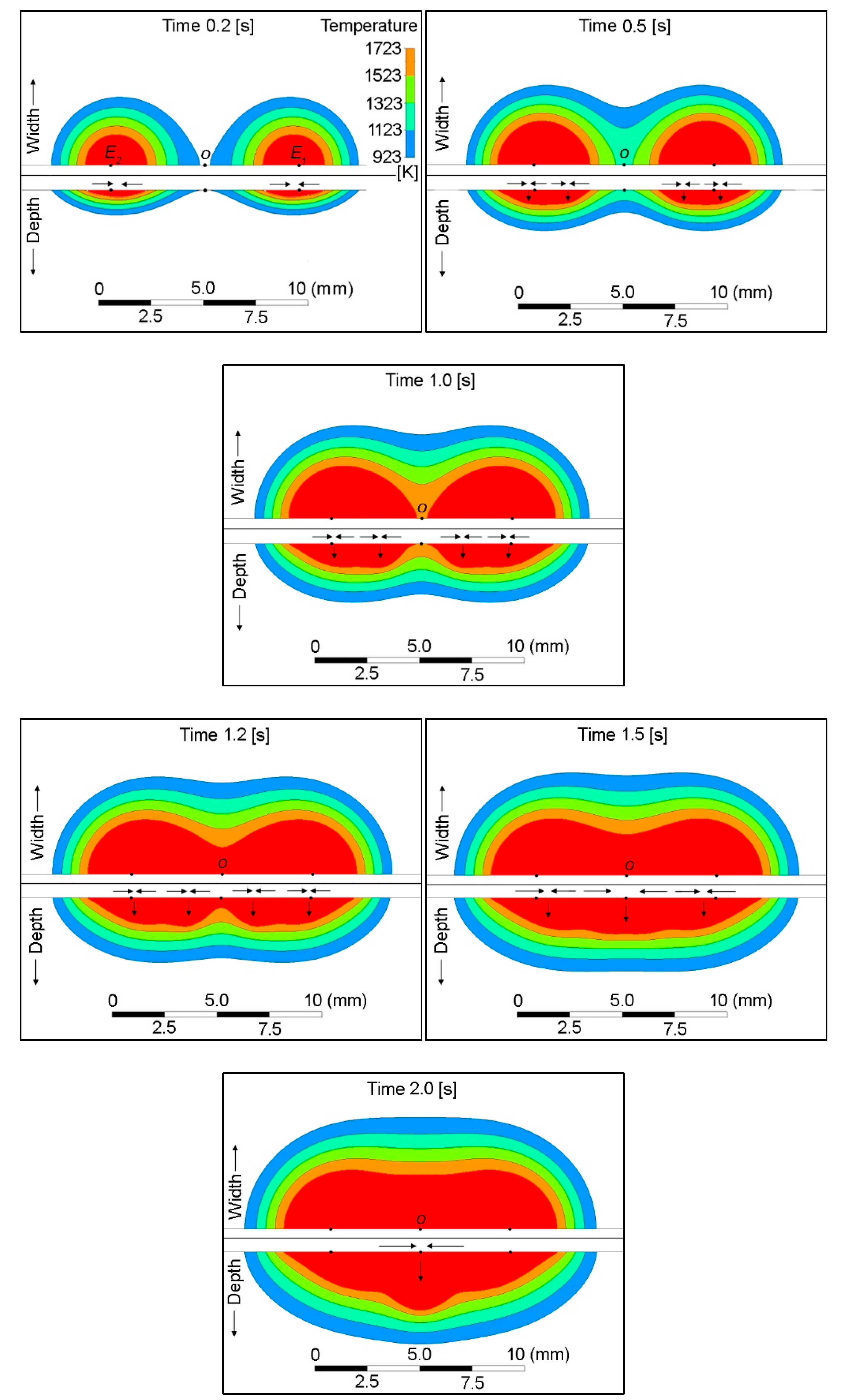
Figure 11.
Stationary weld pool development over time: Double-electrode with background current.
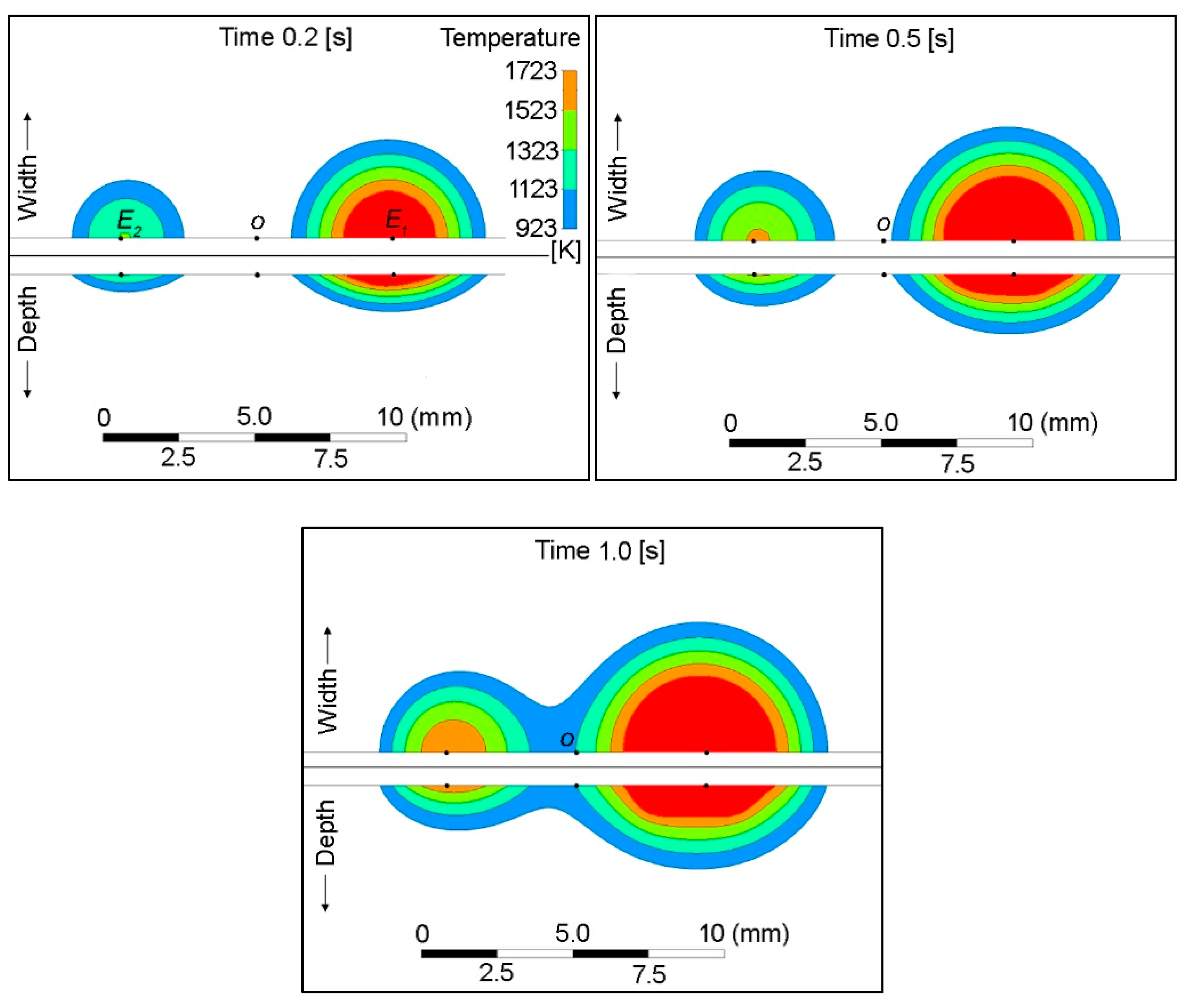
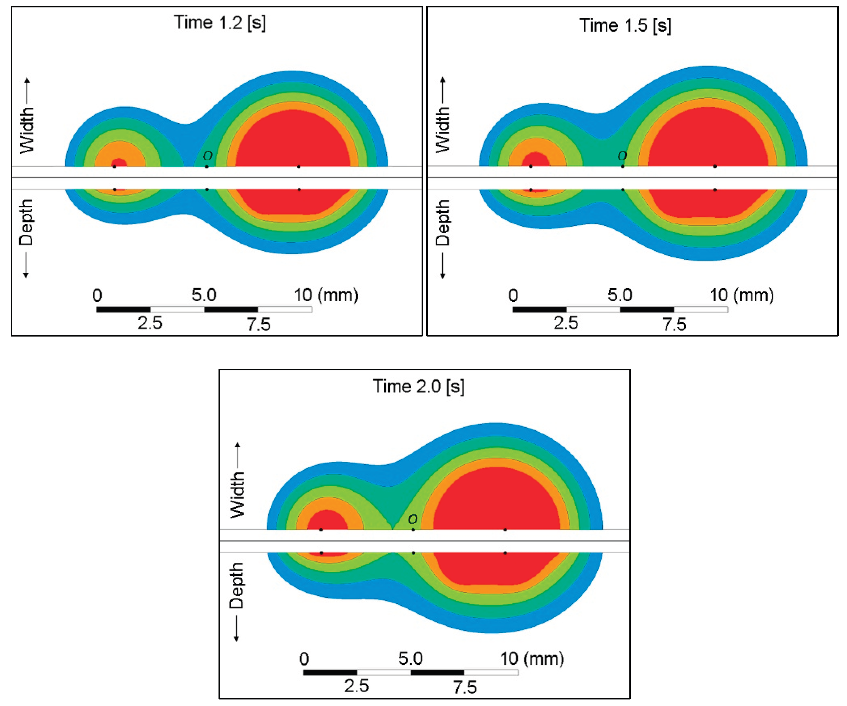
Figure 12.
Moving weld pool (a) DC single (b) DC double (c) PC double at background current (d) PC double at peak current.
Figure 12.
Moving weld pool (a) DC single (b) DC double (c) PC double at background current (d) PC double at peak current.
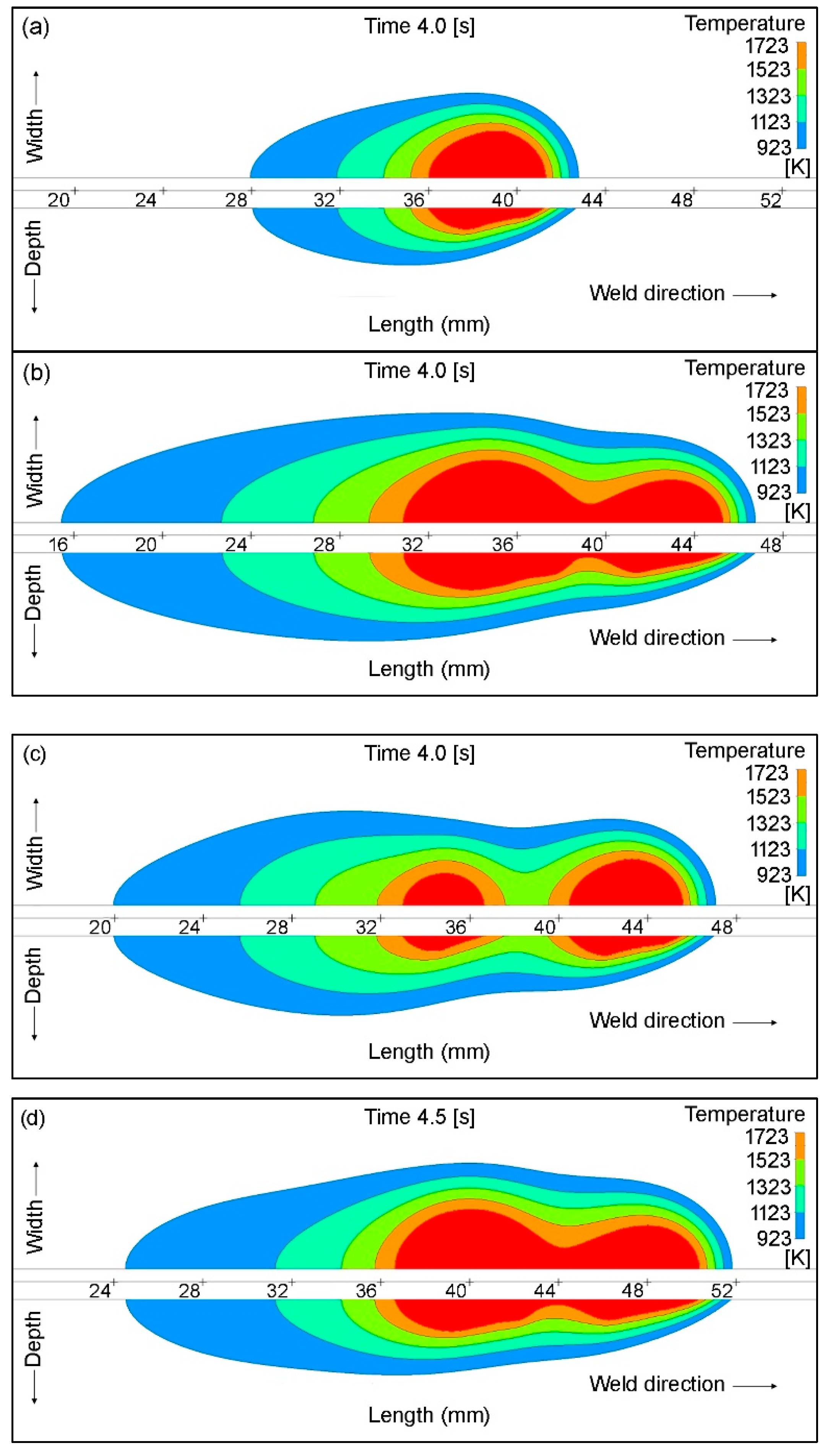
Figure 13.
Comparison of the moving weld pools.
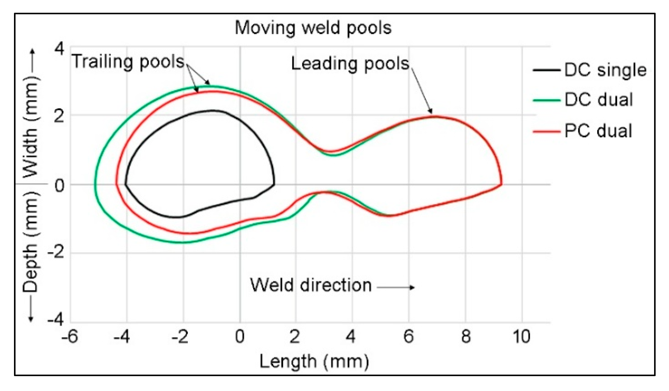

Table 1.
Welding parameters.
| Parameter | Value |
|---|---|
| Peak current | 130 A |
| Background current | 52 A |
| Pulse frequency | 1 Hz. |
| Argon flow rate | 14 l/min |
| Tungsten electrode dia. | 3.2 mm |
| Arc gap | 2 mm |
| Electrode tip angle | 60o |
| Electrode spacing | 9 mm |
| Welding velocity | 10 mm/s |
Table 2.
Analyses conducted in this study
| S. No | Simulation | Weld length | Analysis type |
|---|---|---|---|
| 1 | Arc with single-electrode | - | Steady state |
| 2 | Arc with double-electrode | - | Steady state |
| 3 | Weld pool with single-electrode | Spot | Transient, 2 s |
| 4 | Weld pool with double-electrode DC | Spot | Transient, 2 s |
| 5 | Weld pool with double-electrode PC | Spot | Transient, 2 s |
| 6 | Weld pool with single-electrode | 50 mm | Transient, 5 s |
| 7 | Weld pool with double-electrode DC | 50 mm | Transient, 5 s |
| 8 | Weld pool with double-electrode PC | 50 mm | Transient, 5 s |
Table 3.
Boundary conditions
| Boundary (Figure 1a) |
Type | Description | Value |
|---|---|---|---|
| a | Wall | Tungsten electrode cross-section | 130 A, 52 A |
| b | Symmetry | Tungsten electrode planar symmetry | - |
| c | Inlet | Argon flow | 14 l/min |
| d | Symmetry | Arc planar symmetry | - |
| e, f | Opening | Open to the atmosphere | 303 K, 1 atm. |
| h | Wall | Top surface of the workpiece with a heat transfer coefficient | 25 W/m2 K |
| i | Symmetry | Workpiece planar symmetry | - |
| j | Wall | Sides of the workpiece with a heat transfer coefficient, and magnetic potential | 25 W/m2 K 0 T m |
| k | Wall | Bottom surface of the workpiece with a heat transfer coefficient, and Electric potential | 25 W/m2 K 0 V |
Disclaimer/Publisher’s Note: The statements, opinions and data contained in all publications are solely those of the individual author(s) and contributor(s) and not of MDPI and/or the editor(s). MDPI and/or the editor(s) disclaim responsibility for any injury to people or property resulting from any ideas, methods, instructions or products referred to in the content. |
© 2025 by the authors. Licensee MDPI, Basel, Switzerland. This article is an open access article distributed under the terms and conditions of the Creative Commons Attribution (CC BY) license (http://creativecommons.org/licenses/by/4.0/).
Copyright: This open access article is published under a Creative Commons CC BY 4.0 license, which permit the free download, distribution, and reuse, provided that the author and preprint are cited in any reuse.


