Submitted:
10 December 2025
Posted:
11 December 2025
You are already at the latest version
Abstract
Leachate in landfills becomes difficult to treat due to its complex and widely variable composition, containing a large amount of organic, inorganic substances and heavy metals. When it seeps into the ground, leachate pollutes groundwater, and if discharged into surface water, it will harm the aquatic environment in the corresponding area. Therefore, it is extremely necessary to treat leachate before discharging it into the environment to prevent this negative impact. In this study, a lab-scale A2O (Anaerobic–Anoxic–Oxic) system integrated with a Moving Bed Biological Reactor (MBBR) was established. We evaluated key water quality indicators of wastewater pretreated by internal electrolysis, the effluent from the A2O–MBBR system, and the combined treatment process. The wastewater was taken from Nam Son landfill, Soc Son, Hanoi, in Viet Nam. COD, BOD5, NH4+-N, and pH of the input leachate wastewater were 2140 mg/L, 250 mg/L, 895 mg/L, and 8 ± 0.5, respectively. The conditions of internal electrolysis were as follows: 120 minutes of reaction time, pH =4, 4.0 g/L Fe/Cu dosage and 100 mg/L PAM dosage. Following the internal electrolysis pretreatment, the removal efficiencies of COD, BOD₅, and NH₄⁺–N reached 49.0%, 4.8%, and 11.2%, respectively. After 24 hours of operation, the integrated treatment process exhibited markedly enhanced performance, achieving removal rates of 85.0% for COD, 85.2% for BOD₅, 94.1% for total nitrogen, 98.0% for total phosphorus, and 96.7% for NH₄⁺–N. These results demonstrate the high synergistic efficiency of the combined internal electrolysis–A₂O–MBBR system. Furthermore, all post-treatment parameters complied with the Vietnamese standard QCVN 40:2011/BTNMT (Column B2) for leachate wastewater, confirming its effectiveness and environmental suitability.
Keywords:
internal microelectrolysis
; Fe/Cu material
; landfill leachate
; A2O
; MBBR
1. Introduction
The landfill process, under the influence of biological and physicochemical processes, generates leachate [1]. Leachate in landfills becomes difficult to treat due to its complex and widely variable composition, containing a large amount of organic, inorganic substances and heavy metals [1,2]. These substances, when discharged into the environment, cause serious pollution. When absorbed into the soil, leachate pollutes groundwater, and if discharged into surface water, it will harm the aquatic environment in the corresponding area. Therefore, it is extremely necessary to treat leachate before discharging into the environment to prevent this negative impact. Particularly at Nam Son landfill, Soc Son, Hanoi, it receives more than 6,000 tons of waste/day and night, at peak times it can reach 7,000 tons/day and night and there are 03 leachate treatment stations with a capacity of 3,700 m3/day and night but still not enough capacity to treat the generated leachate [3,4]. The leachate at Nam Son landfill site contains many organic components that are difficult (or not) to biodegrade. Inorganic components, especially ammonia (NH3) in the form of NH4+, have a very high content, are stable and change little over time and this is the most difficult component to change in leachate.
Recently, in the world, there have been many studies and applications of internal electrolysis methods in wastewater treatment, especially industrial wastewater, textile dyeing, coking, leachate…et al. [5,6,7,8].
Internal electrolysis has recently emerged as a promising technique for the pretreatment of wastewater containing pollutants with low biodegradability and high concentrations. This technology has been successfully applied in various industrial sectors, including textiles, pharmaceuticals, paper manufacturing, fertilizer production, and pesticide processing [9,10,11,12].
In general, the key electrochemical reactions occurring during the internal electrolysis process can be represented as follows [13,14,15,16,17]:
Anode (Fe): Fe → Fe²⁺ + 2e⁻ E⁰(Fe²⁺/Fe) = –0.447 V
Cathode (C): 2H⁺ + 2e⁻ → H₂ E⁰(H⁺/H₂) = 0.00 V
The reaction efficiency of zero-valent iron (Fe⁰) can be further enhanced by integrating the internal electrolysis process with a carbon-based electrode, which provides a higher potential difference and improved electron transfer capacity [18,19,20,21,22,23,24].
When organic compounds such as RX (organic chlorinated compounds) or RNO₂ (aromatic nitro compounds) are present in the wastewater, they can act as electron acceptors at the anode surface (Fe). These substances undergo reductive dechlorination and amination reactions [10,12,18,19,20], converting hazardous pollutants into non-toxic or less toxic products with higher biodegradability. The main reduction reactions proceed as follows:
RX + H+ + e- → RH + X-
RNO2 + 6 H+ + 6 e- → RNH2 + 2 H2O
In addition, in the solution, there will also be a reaction between Fe2+ and these organic substances according to the reaction:
RX + Fe2++ H+ + e- → RH + X- + Fe3+
RNO2 + 6 H+ + 6Fe2+ → RNH2 +2 H2O + 6 Fe3+
When O2 is present in an acidic environment:
O2 + 4H+ + 4e = 2H2O E0(O2/H2O) = 1.23V
In neutral and alkaline environments:
O2 + 2H2O +4e = 4OH-, E0 (O2/OH-) = 0.41V
The process occurs internal electrolysis reaction, for pollutants will be decomposed with the following 6 main effects [4,10,11,12]:
(1) Effect of the Electric Field: In the micro-cell system formed within the wastewater, an electric field is generated, causing charged pollutants to migrate toward oppositely charged electrodes. At the electrode surfaces, oxidation–reduction reactions occur, resulting in the alteration or breakdown of the chemical structures of these pollutants. Consequently, many recalcitrant compounds are transformed into simpler or less harmful substances through electrochemical processes.
(2) Reductive Effect of Hydrogen: Iron (Fe) possesses strong reducing properties. In an acidic environment, the following reaction takes place:
Fe + 2H⁺ → Fe²⁺ + 2[H]
This reaction generates atomic hydrogen ([H]) on the electrode surfaces. The nascent hydrogen atoms exhibit high reducing activity, enabling them to convert certain pollutants in solution. For instance, compounds containing nitro (–NO₂) groups can be reduced to their corresponding amine derivatives, significantly decreasing toxicity and improving biodegradability.
(3) Effect of Metallic Iron: Metals positioned below iron in the electrochemical activity series can undergo electron exchange on the surface of metallic iron. As a result, highly toxic metal ions or organic substances can be reduced by Fe⁰ to less toxic or more stable forms. For example, hexavalent chromium [Cr(VI)], a strong oxidizing species with a standard electrode potential of E⁰(Cr₂O₇²⁻/Cr³⁺) = 1.36 V, is reduced to trivalent chromium [Cr(III)] in an acidic medium according to the following reaction:
2Fe + Cr2O72- + 17 H+ = 2Fe3+ + 2Cr3+ + 7H2O
Subsequently, Cr(VI), a species with strong oxidizing properties, is reduced to Cr(III), which exhibits much weaker reducing characteristics. Similarly, in acidic environments, metallic iron can effectively reduce organic compounds containing nitro (–NO₂) groups to their corresponding amino (–NH₂) derivatives, as illustrated by the following reaction:
C₆H₅NO₂ + 3Fe + 6H⁺ → C₆H₅NH₂ + 3Fe²⁺ + 2H₂O
(4) Reductive Effect of Fe²⁺ Ions:
During the electrochemical process, iron is oxidized to ferrous ions (Fe²⁺), which possess strong reducing capabilities. These ions can further reduce Cr(VI) to Cr(III) through the following reaction:
6Fe²⁺ + Cr₂O₇²⁻ + 14H⁺ → 6Fe³⁺ + 2Cr³⁺ + 7H₂O
In the case of pollutants such as azo dyes, the chromophoric –N=N– groups are reduced by Fe²⁺ ions to yield amine compounds, resulting in significant color removal from the wastewater. The reaction proceeds as follows:
4Fe²⁺ + R–N=N–R′ + 4H₂O → RNH₂ + R′NH₂ + 4Fe³⁺ + 4OH⁻
(5) Coagulation Effect of Iron Ions:
Under acidic conditions, metallic iron undergoes corrosion, releasing substantial amounts of Fe²⁺ and Fe³⁺ ions. In the presence of oxygen and under slightly alkaline conditions, the following reactions take place:
Fe²⁺ + 2OH⁻ → Fe(OH)₂
4Fe²⁺ + 8OH⁻ + O₂ + 2H₂O → 4Fe(OH)₃
The freshly generated Fe(OH)₂ and Fe(OH)₃ exhibit strong adsorption and flocculation capacities toward high–molecular–weight organic substances. Through the internal electrolysis process, pollutants are first chemically transformed, after which the newly formed intermediates are effectively coagulated and removed by Fe(OH)₃ precipitates.
(6) Coagulation effect:
Fe2+ and Fe3+ ions in water when encountering inorganic elements will produce a precipitation reaction into compounds such as: FeS, Fe3[Fe(CN)6]2 and Fe4[Fe(CN)6]3… These compounds will quickly settle down and be easily removed.
In summary, the internal electrolysis reaction will have 6 main effects on organic pollutants. Pollutants with stable chemical structures are reduced to less stable and more biodegradable substances. Thanks to that, the following biological treatment processes will be more effective because then in the metabolic process, microorganisms easily consume and decompose pollutants to grow and develop.
The treatment efficiency of the internal electrolysis method depends on the composition of industrial wastewater. The internal electrolysis process can achieve the following treatment efficiency:
The first, applicable to many types of industrial wastewater that are difficult to treat: polyester wastewater [4,10,19], dye wastewater [25], coal gasification wastewater [9], pesticide wastewater [4,20,21], nitrate-contaminated wastewater [14], mixed industrial wastewater (textile, dyeing, paper, electroplating, mechanical) [15,17,22], wastewater rich in organic matter [9,11,17], wastewater containing oil [18], wastewater contaminated with TNT and RDX [4,10].
The second, highest treatment effect, fast reaction time, low operating cost. Jin Hong Fan and Lu Min Ma [2008, 2009] used Fe/Cu electrode system to treat industrial wastewater at Tao Pu industrial park, Shanghai with a capacity of 60,000 m3/day and night, COD removal efficiency reached 40% [4]. Xiangli Yin (2009) used this method connected with external current to treat 4-Chlorophenol, after 36 minutes of treatment, more than 90% of pollutants were removed. Xiao Yi Yang [2009] used the method to treat polyester wastewater after 38 hours of treatment, the COD removal efficiency reached 58%, reduced from 3353.2 mg/L to 1391.6 mg/L, the biodegradability of the BOD5/COD ratio increased from 0.27 to 0.42 [18]. Q. Zhu (2014) integrated the internal electrolysis process with a biofilm reactor for the treatment of mixed industrial wastewater, resulting in a remarkable decrease in COD from 150,000 mg/L to 500 mg/L [17], demonstrating the high synergistic efficiency of the combined system.
The reactions in the internal electrolysis process of leachate treatment include electrode reactions and reduction reactions of organic compounds.
Organochlorine compounds and aromatic nitro compounds are reduced by the dechlorination and amination reactions as described above.
The reaction to remove humic acid in leachate in the internal electrolysis method occurs as follows [26,27]:
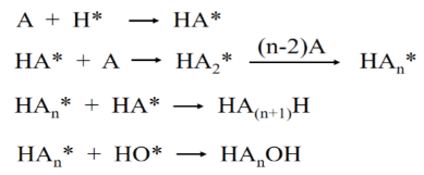
In which HA is humic acid, H* is atomic hydrogen.

Table 1.
Research results on internal electrolysis method for treating leachate.
| Method | Materials | Conditions treament | Efficiency | Ref |
|---|---|---|---|---|
| Electrolysis + Fenton | Fe/C + H2O2 | Mass ratio Fe:C = 1:1; pH = 5; Processing time 300 minutes; H2O2 | COD removal 90.9%; color 84.4%; humic acids 72.8% | [7] |
| Electrolysis + Fenton | Fe/C + H2O2 | Mass ratio Fe:C = 3:1, mass of material Fe/C 55.72 g/L; pH = 3.12; H2O2 concentration 12.32 mL/L | COD removal 74.6%; BOD5/COD is 0.5 | [26] |
| Electrolysis + Fenton | Fe/C + H2O2 | Surface area ratio C:Fe = 717143.8; pH = 3.8; H2O2 concentration 1687.6 mg/L | COD removal 86.9% | [27] |
| Electrolysis + Fenton | Fe/C + H2O2 | Mass of Fe/C 104.52 g/L; pH = 3.2; H2O2 concentration is 3.57 g/L | COD removal 90.27%; humic acids 93.79%. | [28] |
| Electrolysis + Fenton | Fe/C + H2O2 | Fe/C mass 52 g/L; Fe:C mass ratio = 3:1; H2O2 concentration 12 mL/L; Processing time 1 h | COD removal 75%; BOD5/COD increased from 0.075 to 0.25. | [29] |
| Electrolysis + Fenton | Fe/C + H2O2 | Fe/C mass is 30~40 g/L; pH = 4; Processing time 1.5 h | COD removal 67.5%; color 92.41%; removal of Ni2+, Cr6+, Pb2+ ions is 96%, 97%, 96%. | [30] |
| Electrolysis + Fenton | Fe/C + H2O2 | Mass ratio Fe:C = 1:1; pH = 5; H2O2 concentration 100 mg/L | COD removal 86.1%; color 95.3%; humic acids 81.8%; BOD5/COD increased from 0.07 to 0.21 | [31] |
| Electrolysis + Fenton | Fe/C + H2O2 | Fe/GAC mass is 10 g/L pH = 3; ratio COD/H2O2 = 1/2 | COD removal 82.1%; BOD5/COD increased from 0.07 to 0.39 | [32] |
| Electrolysis + Fenton | Cast iron + H2O2 |
Fe0: 75 g/L, pH: 3.0. H2O2: 195.6 |
COD removal after internal microelectrolysis 38.2%, after internal microelectrolysis/H2O2 65.1% | [33] |
| Electrolysis + Fenton | Fe/C + H2O2 | pH of 5, Fe/C of 1:1, gas flow rate of 80 Lh-1, and H2O2 of 100mgL−1. | Removal efficiencies of COD (86.1%), color (95.3%), and humic acids (81.8%) | [34] |
| Electrolysis + Fenton | Fe/C + H2O2 | Fe/GAC: 3.0 pH 4, H2O2: 0.75 mM Air flow rate: 200 L/h |
Removal efficiencies COD: 79.2%, colour: 90.8%, BOD5/COD in the final effluent increased from 0.03 to 0.31 | [35] |
| Micro-electrolysis | Fe/C | pH 2.0; GAC 10 g/L; Fe0/GAC: 2/1; Time 90 min |
Removal: COD 85%, Increase in ratio: BOD5/COD 0.31 | [36] |
| Micro-electrolysis | Fe/AC | pH 3, Fe/AC: 12/4 g/L Time: 20 min |
Removal: COD 46% Total nitrogen: 54% |
[37] |
| Electrolysis + Fenton | Fe/C + H2O2 | Dose of H2O2 (27.5%) 25 L four times diluted | Removal: COD 85% Metal content >60% |
[38] |
| Micro-electrolysis O3/OH− /H2O2 |
Fe/GAC | Fe/GAC 20/80 g/L pH 3, |
Removal: COD 76.7% Total COD removal 95.4% at internal microelectrolysis O3/OH-/H2O2 | [39] |
|
Fe0/H2O2 process |
Fe0/H2O2 | pH 3, time: 60 min, COD/H2O2 ratio of 1:4 |
75% TOC removal, BOD5/COD ratio from 0.13 to 0.43 | [40] |
Biological wastewater treatment systems are widely employed for the removal of organic and inorganic contaminants from wastewater. Previous studies on leachate treatment have predominantly focused on conventional biological processes such as Anaerobic–Aerobic (AO), Anaerobic–Anoxic–Oxic (A₂O), Upflow Anaerobic Sludge Blanket (UASB), Sequencing Batch Reactor (SBR), Fluidized Bed Reactor (FBR), Membrane Bioreactor (MBR), and Moving Bed Biofilm Reactor (MBBR) systems [6,8,13,16,25,41,42,43].Recent advancements, however, have highlighted that the integration of these systems—particularly the combination of the A₂O (Anaerobic–Anoxic–Oxic) process with a Moving Bed Biofilm Reactor (MBBR)—can yield significant advantages. Such hybrid configurations enhance pollutant oxidation and decomposition under anaerobic conditions, effectively reducing pollutant concentrations and toxicity, thereby improving overall biodegradability [5,44,45]. Biofilm reactor technologies have demonstrated exceptional performance, achieving up to 98% removal of biochemical oxygen demand (BOD₅) and chemical oxygen demand (COD), thus ranking among the most efficient systems for wastewater purification [46,47]. Moreover, the presence of mobile carrier media facilitates improved nitrogen removal through enhanced nitrification and denitrification processes within the reactor [48,49].
In the present study, we aim to enhance the treatment efficiency of landfill leachate by investigating key operational parameters of the internal electrolysis process. The experimental approach involves pretreatment using Fe/Cu-based internal electrolysis, followed by biological treatment in an integrated A₂O–MBBR system. Furthermore, the study evaluates the synergistic performance of the combined process in which pretreatment internal elecolysisis applied prior to the A₂O–MBBR stage.
2. Materials and Methods
2.1. Fabrication of Fe/Cu Material
Analytical-grade chemicals were used in all experiments. Iron powder (<50 µm, 99.9% purity), graphite powder (<50 µm, 99.95% purity), and ammonium carbonate ((NH4)2CO3) were obtained from PA, China. The Fe/Cu composite material was synthesized following the procedure described in previous studies [15,22]. Initially, Fe powder (<50 µm, 99.9% purity) was pretreated to remove surface impurities. The powder was immersed in a 30 wt% NaOH solution for 10 minutes to eliminate grease and surface contaminants, followed by surface activation in a 5 wt% HCl solution for 3 minutes. The dilute HCl solution was prepared from a concentrated HCl stock solution (37 wt%). The pretreated Fe powder was subsequently rinsed several times with deionized water, dried at 105 °C for 2 hours, cooled to room temperature, and stored in a sealed glass container.
The Fe/Cu composite was prepared via a chemical plating process using a 5 wt% CuSO₄ solution. Specifically, 100 g of the pretreated Fe powder was added to 1 L of the CuSO₄ solution and stirred for 2 minutes to facilitate Cu deposition on the Fe surface. The resulting mixture was washed repeatedly with deionized water to remove residual ions and then dried at 105 °C for 3 hours under a nitrogen atmosphere. The synthesized Fe/Cu material was stored in a desiccator until further use.
2.2. Collection of Landfill Leachate
Characteristics of leachate at Nam Son landfill over time are given in Table 2. The composition of organic pollutants is characterized by very high COD and BOD. For landfill time of 2-3 years, leachate has a very high COD value (30,000-60,000 mg/L), COD/BOD ratio is also high (>0.6), showing that this leachate contains many organic components that are easily biodegradable. In contrast to landfill time of over 3 years, leachate has a low COD (100-2000 mg/L), COD/BOD ratio is also low (<0.3), proving that leachate corresponding to long landfill time contains many organic components that are difficult (or not) to biodegrade.
2.3. Establishment of the A₂O–MBBR System
2.3.1. Cultivation of Aerobic Activated Sludge
Aerobic activated sludge was obtained from the Nam Son landfill leachate treatment plant and inoculated with nitrifying bacterial strains exhibiting strong ammonia-oxidizing activity. The sludge was enriched by adding 1 L of wastewater pretreated through internal electrolysis and supplemented with nutrients at a C:N:P ratio of 200:5:1, along with 1.0 g of a commercial microbial preparation designed for high-ammonium wastewater treatment.
The dissolved oxygen (DO) concentration in the aeration tank was maintained between 1.5 and 3.0 mg/L. Air was supplied continuously for 12 hours, followed by a 2-hour settling period. The supernatant was then decanted, and new wastewater and nutrients were added. This procedure was repeated daily for one week, after which the aeration time was reduced to 6 hours per cycle. The acclimation of aerobic sludge was carried out at ambient temperature, with the pH maintained between 6.5 and 7.0, over a period of four weeks.
2.3.2. Cultivation of Anoxic Activated Sludge
Anoxic activated sludge was also sourced from the Nam Son landfill leachate treatment facility. The sludge was mixed with 1 L of wastewater pretreated by internal electrolysis and supplemented with nutrients to maintain a C:N:P ratio of 150:5:1, together with 1.0 g of microbial preparations specialized for the degradation of high-ammonium wastewater.
The DO concentration in the anoxic reactor was maintained between 1.0 and 2.0 mg/L. Each operational cycle consisted of 24 hours of anoxic incubation followed by 2 hours of settling. After settling, the supernatant was decanted and replaced with fresh wastewater and nutrients. The domestication process was conducted at room temperature, under pH conditions of 6.5–7.0, for approximately 30 days.
2.3.3. Cultivation of Oxic Activated Sludge
The cultivation procedure for oxic activated sludge was identical to that employed for the anoxic sludge, ensuring consistent microbial activity and stability prior to integration into the A₂O–MBBR system. Add more treated wastewater in the anaerobic tank, ensure safe nutrient source: C:N:P=100:5:1. Use an air machine to create an aeration environment. Blow air for 24 hours, then let it settle for 2 hours. Remove the clear water; Continue to add artificial wastewater and nutrient source. The acclimatization process is carried out at room temperature; pH value = 6.5-7.5, for 30 days.
Figure 1.
Activated sludge culture in the laboratory. (a) Anaerobic tank; (b) anoxic tank; (c) Oxic tank.
Figure 1.
Activated sludge culture in the laboratory. (a) Anaerobic tank; (b) anoxic tank; (c) Oxic tank.
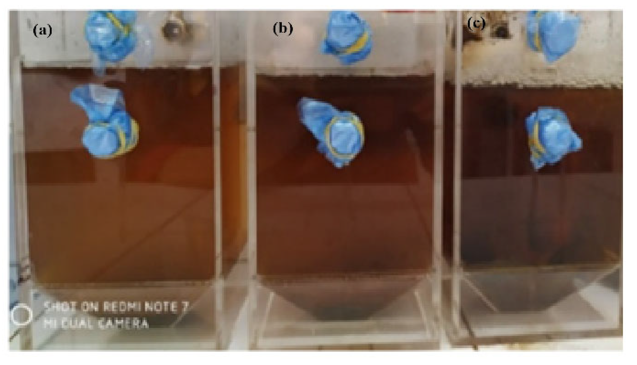
Figure 2 illustrates the configuration of the A₂O–MBBR system. Each reactor has a working volume of 3 L and is equipped with multiple influent and effluent ports, allowing precise control of hydraulic retention times and facilitating experimental manipulation.
2.3.4. Activated Sludge Culture
Following the determination of initial operational parameters, wastewater pretreated by internal electrolysis (pH adjusted to 7) was introduced into the A₂O–MBBR system. The hydraulic retention times were set as follows: 24 hours in the anaerobic tank, 6 hours in the anoxic tank, and 4 hours in the aerobic tank.
Aeration in the aerobic tank was controlled to maintain a dissolved oxygen (DO) concentration of 5–8 mg/L. In the anoxic tank, DO was maintained at 1–2 mg/L through mechanical stirring for 150 minutes using a paddle with a length of 3 cm. All tanks were supplemented with MBBR-type biochips, with 1 g of carrier media added per liter of wastewater to support biofilm development.
Table 3.
Presents the initial operating parameters of the A₂O–MBBR system, including the mixed liquor suspended solids (MLSS) concentration of the activated sludge.
Table 3.
Presents the initial operating parameters of the A₂O–MBBR system, including the mixed liquor suspended solids (MLSS) concentration of the activated sludge.
| Reaction Tank | COD (mg/L) | MLSS (mg/L ) | pH | DO (mg/L) | Retention Time (h) |
|---|---|---|---|---|---|
| Anaerobic | 1090 | 3043 | 7-8 | - | 14 |
| Anoxic tank | 2085 | 1-2 | 6 | ||
| Aerobic | 1123 | 5-8 | 4 |
2.4. Methods and Instruments
The as-synthesized Fe/Cu composite material was characterized using several analytical techniques. Surface morphology and elemental composition were examined by scanning electron microscopy coupled with energy-dispersive X-ray spectroscopy (SEM–EDS, S4800, Hitachi), while crystal structure was analyzed by X-ray diffraction (XRD, Siemens/Bruker, D5000).
Chemical oxygen demand (COD), biochemical oxygen demand (BOD₅), and ammonium (NH₄⁺–N) concentrations were measured following standard protocols: SMEWW 5220D:2012 for COD, TCVN 6001-1:2008 for BOD₅, SMEWW 5530C:2012 and SMEWW 4500CN.C&E:2012 for NH₄⁺–N, and TCVN 6660:2000, respectively. All analyses were conducted at VILAS 424, VIMCERTS 054, Environmental Analysis, Hydraulic Monitoring Center.
3. Results
3.1. Surface Characteristics and Physical Properties of Fe/Cu Materials
3.1.1. SEM–EDS Analysis of Fe/Cu
SEM–EDS analysis (Figure 3) revealed notable differences between the surface morphology of the pristine Fe powder and the synthesized Fe/Cu. The Fe powder exhibited block-like aggregates with overlapping particles, whereas in the Fe/Cu material, Fe and Cu particles were uniformly distributed across the surface, with particle sizes below 50 µm. This observation indicates the formation of Fe/Cu micro-cell pairs, where Cu plating was evenly deposited on Fe particles. The corresponding EDS spectra (Figure 3 and Figure 4, Table 4) further confirmed the elemental composition and relative content in each sample, demonstrating successful incorporation of Cu onto the Fe matrix.
3.1.2. XRD Analysis of Fe/Cu
X-ray diffraction (XRD) analysis of the Fe/Cu material is presented in Figure 5. The XRD patterns show that the characteristic peaks of Fe are significantly attenuated, indicating that the Fe surface is effectively covered by a Cu layer. This observation confirms the successful fabrication of the Fe/Cu bimetallic material, with Cu uniformly coating the Fe surface to form Fe/Cu micro-cell (micro-battery) pairs.
3.2. Effect of Experimental Parameters on the Efficiency of Landfill Leachate Treatment by Internal Electrolysis Method
For the aim of determining the factors affecting the treatment efficiency by internal electrolysis method, we have surveyed and researched, the main factors studied include: 1. Treatment time; 2. pH; 3. Fe/Cu material dost; 4. Shaking speed
Evaluation of the treatment efficiency of the leachate pre-treatment process. The experiment with 2.0, 3.0, 4.0, 5.0 and 6.0 g of internal electrolytic material/1 liter of leachate, reaction temperature 25℃, shaking speed 60, 90, 120, 150 rpm, for 1, 2, 3, 5 and 6 hours, pH value = 2, 3, 4, 5, 6,7. Then adjust pH = 7, add 0.1 g/L PAM, let it settle, take the clear water for analysis. Then biological treatment A2O, with the following biological treatment time conditions: Anaerobic 14 hours, anoxic 6 hours, aerobic 4 hours.
3.2.1. Effect of Treatment Time
-COD Removal Efficiency
The leachate sample was tested at the following conditions: pH=4, Fe/Cu dosage 5.0 g/L, shaking speed 120 rpm. In the pretreatment process by internal electrolysis method, the treatment time has a great influence on the treatment efficiency and is of great value in the system design. Therefore, it is necessary to determine the retention time under which conditions is suitable for the treatment of leachate, ensuring the design and operation process is optimized.
Figure 6.
COD removal efficiency over time by internal electrolysis method.
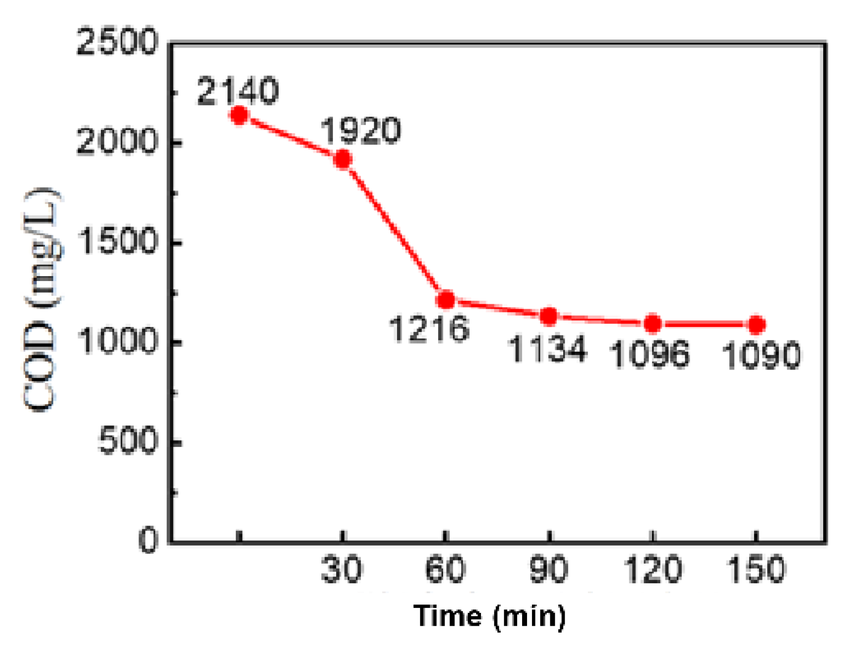
The COD results obtained in 6, it can be seen that in the first 60 minutes, the internal electrolysis reaction occurs relatively quickly, the COD content decreases rapidly, after 60 minutes of treatment, COD decreases from 2140 mg/L to 1216 mg/L. Then COD gradually decreases during the treatment time from 60 to 150 minutes. COD decreased significantly, proving that using internal electrolysis method gives high treatment efficiency.
Total N and Ammonium Removal Efficiency
The leachate sample was tested at the following conditions: pH=4, Fe/Cu dosage 5.0 g/L, shaking speed 120 rpm. The effect of time on the removal results of N and NH4+ can be seen in Figure 7. It can be seen that the total N and NH4+ content almost did not decrease after different treatment times. This result is consistent with previous studies, many reports have shown that the internal electrochemical process has no effect on removing N and NH4+. In Figure 7, after 150 minutes of treatment, the total N and NH4+ decreased but not significantly, this is due to the iron ions forming the precipitated flocculant. During the internal electrochemical treatment process, sometimes under the effect of redox reactions, the functional groups on high molecular organic matter are separated and may lead to an increase in the total N and the amount of NH4+ after treatment.
P Removal Efficiency
The leachate sample was tested at the following conditions: pH=4, Fe/Cu dosage 5 g/L, shaking speed 120 rpm. Figure 8 shows that total phosphorus decreased rapidly in the first 90 minutes of treatment of the internal electrolysis process, when increasing the treatment time to 120 minutes and 150 minutes, total P decreased slightly. In acidic environment, PO4- radicals in leachate mostly exist in the form of H2PO4- during the internal electrolysis process, these radicals easily combine with Fe2+ and Fe3+ ions according to the reaction:
Fe2+ + H2PO4- → FeH2PO4+
Fe3+ + H2PO4- → FeH2PO42+
During the first 120 minutes of treatment, a large amount of iron is oxidized to form Fe2+ and Fe3+ ions, so a large amount of PO4- radicals combine with iron ions to form iron salts and are removed from the wastewater. Therefore, total P decreases rapidly and is almost completely removed during the first 120 minutes of treatment. At treatment times of 60, 90, 120 and 150 minutes, the P removal rates are 73.6, 86.5, 92.7 and 93.4 %.
The results of the analysis of the effect of treatment time on the removal efficiency of COD, N and total P showed that the treatment time of 120 and 150 minutes gave a clear effect on the treatment of leachate. If the treatment time is increased, a large amount of electricity will be consumed for the treatment process and the internal electrolytic material will continue to be corroded. Therefore, the retention time at 120 minutes is reasonable.
3.2.2. Effect of pH
The pH in the electrolysis process affects the amount of oxidized iron, the amount of H+ ions and the amount of OH* radicals. Therefore, it can be seen that pH is an important factor in the treatment of domestic electrical waste. The results of the survey on the influence of pH on the COD removal rate, color and BOD5/COD value can be seen in Figure 9 and 10.
The results in Figure 7 show that the COD and color removal rates decrease gradually as the pH increases. At pH values of 3 and 4, the COD removal rates are 50.2 and 49.5%, the color removal rates are 69.0 and 67.6%, respectively, which can be seen that the difference between these values is not much. When the pH increases, the COD and color removal efficiency decreases significantly, at pH 6 and 7, the COD removal rates are only 15.6 and 8.4%, the color removal rates are 20.6 and 10.5%.
From this result, it can be seen that in acidic environment, the internal electrolytic reaction will give better treatment efficiency. The main reason is that in acidic environment, the microcells created by Fe/Cu bimetallic material have higher voltage, thereby promoting corrosion at the iron electrode and the redox reaction on the electrode takes place more easily, Fe2+ ions in the oxidizing environment are also easily oxidized into Fe3+ ions. The result of this process is to create a large corrosion current and corrosion potential, thereby increasing the corrosion rate, or the ability to decompose organic substances in wastewater. In addition, the acidic environment is also beneficial for the formation of OH* free radicals. Research results have shown that in the internal electrolysis reaction, the concentration of OH* free radicals is inversely proportional to the third power of pH. Therefore, low pH environmental conditions will be beneficial for the formation of OH* free radicals, thereby enhancing the ability to remove pollutants in wastewater. However, when the pH is too low, the amount of iron is corroded, forming too much Fe2+ ions, which will also suppress the OH* free radicals. In addition, too high an amount of H+ ions will also easily cause the reaction H+ + OH- -> H2O, which will reduce the amount of OH* free radicals. On the other hand, when the pH is too low, the amount of dissolved iron is too high, which will also increase the color of the wastewater or make the iron content higher than the prescribed level, besides, it will also hinder the process of Fe2+ converting into salt deposits, thereby reducing the treatment efficiency. In neutral or alkaline environments, the amount of iron corroded is low, because the corrosion potential of the Fe/Cu material is proportional to the amount of iron ions generated, so at this time the electrode potential and corrosion current generated by the micro-cell system are low, resulting in weak electrode reaction, poor waste decomposition rate and reduced treatment efficiency. In addition, Fe(OH)2 covering the surface of the Fe/Cu material also reduces the contact of waste with the material surface, thereby reducing the treatment efficiency of the internal electrolysis process.
The BOD5/COD value varies with the pH value as shown in Figure 10. The experimental results show that the BOD5/COD value is inversely proportional to the pH. At low pH values, the BOD5/COD treatment results are higher and vice versa. The BOD5/COD value can reach 0.279 and 0.271 at pH 3 and 4, when the pH increases to 6 and 7, the value is 0.15 and 0.12. It can be seen that in an acidic environment, the BOD5/COD treatment efficiency will be higher, or in other words, after the treatment process, the wastewater will have a higher biodegradability.
From the results of the analysis of the effect of pH on the efficiency of leachate treatment, it can be seen that pH values of 3 and 4 give high treatment efficiency. In the actual operation of the leachate treatment system, when adjusting the pH to a lower level, a large amount of acid is needed, which increases the operating cost. Therefore, combined with the results of the analysis of the effect of pH on the treatment efficiency, the topic chooses the appropriate pH of 4
3.2.3. Effect of Shaking Speed
The internal electrolysis process for leachate treatment occurs at the Fe/Cu material surface, representing a heterogeneous reaction across solid–liquid–gas interfaces. Consequently, the shaking speed plays a critical role by enhancing dissolved oxygen (DO) levels, promoting the diffusion of pollutants toward the Fe/Cu electrode surfaces, and facilitating the rapid dispersion of reaction products from the electrodes into the bulk solution. The influence of shaking speed on the treatment efficiency of landfill leachate is summarized in Figure 11 and Figure 12, highlighting its importance in optimizing mass transfer and electrochemical reaction rates.
The influence of shaking speed on COD removal was systematically investigated. Results indicated that the COD removal efficiency increased sharply as the shaking speed was raised from 60 to 90 rpm, but then showed only marginal improvement as the speed increased from 90 to 150 rpm. Specifically, COD removal rates were 30.5% at 60 rpm, 50.2% at 90 rpm, 50.9% at 120 rpm, and 51.4% at 150 rpm. A similar trend was observed for the BOD₅/COD ratio (Figure 12), which increased rapidly from 60 to 90 rpm and then stabilized at higher speeds. These findings suggest that increasing the shaking speed beyond 90 rpm does not significantly enhance leachate treatment efficiency. Furthermore, higher shaking speeds lead to increased energy consumption and greater mechanical wear of equipment. Therefore, a shaking speed of 90 rpm was selected as the optimal operating condition for the practical design of the leachate treatment system..
Through The observed influence of shaking speed on leachate treatment efficiency can be attributed to two main factors:
(1) Enhanced Liquid–Solid Contact: Higher agitation speeds improve the interaction between the leachate and the Cu cathode electrochemical catalyst surface. Increased stirring facilitates the transport of wastewater, intermediate decomposition products, and reactants between the liquid phase and the Fe/Cu solid surface, thereby enhancing reaction rates.
(2)Increased Dissolved Oxygen Concentration: Elevated shaking speeds promote the dissolution of oxygen from air into the solution. In the internal electrolysis process, Fe serves as a sacrificial anode undergoing self-corrosion, while at the cathode, dissolved oxygen is reduced and reacts with H⁺ in the acidic medium to generate H₂O₂. The freshly produced Fe²⁺ from the sacrificial anode subsequently participates in a Fenton reaction, producing highly reactive hydroxyl radicals (OH*) that strongly oxidize organic pollutants in leachate [31,32].
Consequently, pollutant removal occurs not only via reduction at the Cu cathode surface but also through advanced oxidation via the Fenton mechanism under acidic conditions during internal electrolysis. These findings provide critical guidance for determining optimal mixing and aeration parameters in practical leachate treatment applications.
3.2.4. Effect of Fe/Cu Dosage
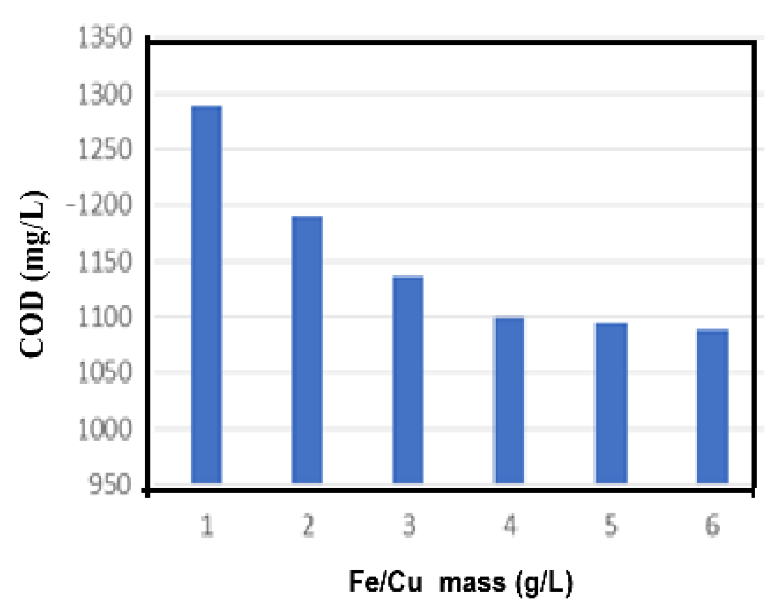
Weigh the Fe/Cu electrolytic internal material into each 250 mL analytical flask with the material mass respectively: 1.0; 2.0; 3.0; 4.0; 5.0; 6.0 g. Add 100 mL of wastewater to each flask, at pH=3. Perform the experiment by shaking on a shaker for 3 hours, shaking speed 120 rpm, at room temperature (~25oC), then determine the COD corresponding to different Fe/Cu dosages.
Figure 13.
Effect of Fe/Cu material dosage on COD treatment efficiency.
Treatment efficiency of the after electrolysis process:
The treatment effect after electrolysis is achieved, experimental conditions: The experiment with 4.0 g of internal electrolytic material/1 liter of leachate, reaction temperature 25℃, shaking speed 12 rpm, for 3 hours, pH value = 4, then adjust pH = 7, add 0.1 g/L PAM, let it settle, take the clear water for analysis. The results are show on table 5.
Table 5.
Leachate treatment efficiency (calculated after the lime treatment stage).
| Parameters | Before treatment | After lime treatment | After electrolysis |
|---|---|---|---|
| COD (mg/L) | 3000-3500 | 2140 | 1090 |
| Total P (mg/L) | 87-90 | 25 | 2 |
| Total N (mg/L) | 1850-2100 | 895 | 790 |
| NH4+ (mg/L) | 450-894 | 325 | 301 |
| pH | 7.2-8.5 | 11 | 6.5-7.0 |
3.3. Wastewater Treatment After Electrolysis by Anaerobic-Anoxic-Oxid Moving Bed Biofilm Reactor (A2O-MBBR)
Pretreatment conditions by internal electrolysis method, with parameters of retention time 3 hours, 4 g/L Fe/Cu, pH = 3, PAM content (0.1g/L), shaking speed 120 rpm, then continued to be treated by AAO biology, using activated sludge acclimatized with anaerobic, anoxic, aerobic tank parameters of 24 hours.
3.3.1. Investigation of Activated Sludge Development
We have studied and evaluated the development of the activated sludge during a 90-day operational trial, the results are shown in Figure 14.
The results showed that the activated sludge content increased rapidly until day 30, the activated sludge mass doubled when the time increased from 15 to 30 days. By day 36, the active mass increased slowly and from day 75 to 90 the active mass began to stabilize.
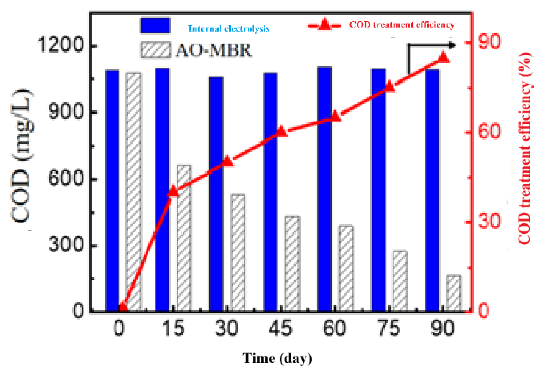
3.3.2. COD Removal Efficiency
Continuously evaluate the COD removal efficiency during the 90-day operational test period, the results are shown in Figure 15.
The results showed that COD treatment efficiency was low (about 40.1%) within 0-15 days. COD efficiency after 90 days of testing reached 85.6%. The remaining COD content was 156 mg/L.
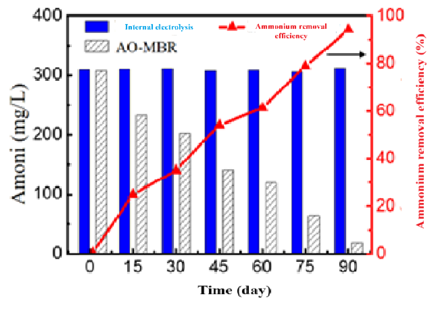
3.3.3. Ammonium Removal Efficiency
The results showed that the ammonium treatment efficiency increased gradually from 0-90 days. After 90 days of testing, the ammonium treatment efficiency was 96.7%, and the total remaining nitrogen was 9.7 mg/L.
Figure 16.
Ammonium removal efficiency over time.
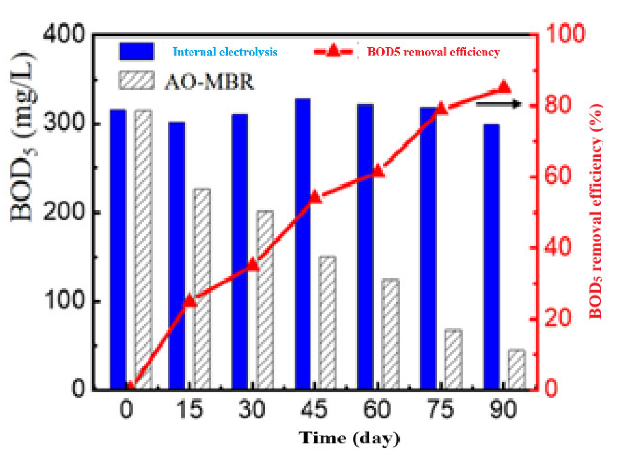
3.3.4. BOD5 Removal Efficiency
The results were seen in the period from 0-90 days of treatment, the BOD5 effect gradually increased. After 90 days of testing, the BOD5 treatment efficiency reached 85.2%, the remaining Total BOD5 was 44.8 mg/L.
Figure 17.
BOD5 removal efficiency over time.
3.3.5. The Treatment Efficiency of the Entire AAO Process
After 90 days of testing, the treatment efficiency of COD, BOD5, total ammonium nitrogen, and P all decreased. At the end of the testing process, we took samples to analyze the above 5 indicators, giving the results in Table 6.
4. Conclusions
The Fe/Cu material was successfully synthesized from Fe powder and CuSO₄ solution and subsequently applied for the treatment of real landfill leachate. The internal electrolysis process was optimized by varying operational parameters, including pH, reaction time, temperature, and Fe/Cu dosage. Optimal treatment performance was achieved after 3 hours at pH 4.0, using 4.0 g of Fe/Cu material per liter of wastewater, and at a temperature of 25 °C. Under these conditions, the internal electrolysis pretreatment achieved removal efficiencies of 49.0% for COD, 4.8% for BOD₅, and 11.2% for NH₄⁺–N. Subsequent treatment with the A₂O–MBBR system for 24 hours further enhanced pollutant removal, yielding reductions of 85.0% for COD, 85.2% for BOD₅, 94.1% for total nitrogen, 98.0% for total phosphorus, and 96.7% for NH₄⁺–N. All post-treatment effluent parameters complied with the Vietnamese standard QCVN 40:2011/BTNMT (Column B2) for landfill leachate wastewater.
This study evaluated two complementary treatment approaches—internal electrolysis with Fe/Cu material and the A₂O–MBBR process—for real leachate wastewater. The results demonstrate that combining internal electrolysis pretreatment with the A₂O–MBBR biofilm system is a promising strategy for efficient landfill leachate treatment and offers potential for practical application in full-scale operations.
Author Contributions
Conceptualization, Van Tu Nguyen; Methodology, Van Tu Nguyen and Vu Duy Nhan; Formal analysis, Van Tu Nguyen and Vu Duy Nhan; Investigation, Van Tu Nguyen; Resources, Van Tu Nguyen and Vu Duy Nhan; Data curation, Van Tu Nguyen; Writing – original draft, Van Tu Nguyen; Writing – review & editing, Van Tu Nguyen and Vu Duy Nhan; Visualization, Van Tu Nguyen; Supervision, Van Tu Nguyen. All authors have read and agreed to the published version of the manuscript.
Funding
This research received no external funding.
Data Availability Statement
The original contributions presented in this study are included in the article. Further inquiries can be directed to the corresponding author.
Acknowledgments
This work was completed with financial support from the Hanoi Department of Science and Technology, Vietnam, under the project 01C-09/03-2018-3.
Conflicts of Interest
The authors declare no conflicts of interest.
References
- V.H. Tap. Research on waste water treatment research by ozonation method. PhD, Academy of Science and Technology/Vietnam Academy of Science and Technology (2015).
- N. H. Khanh. Comparative study of domestic and foreign technologies for leachate treatment, on that basis, propose leachate treatment technology to meet type B according to Vietnamese standards (TCVN) for landfills in Hanoi city. Institute of Environmental Technology (2007), Vietnam Academy of Science and Technology.
- D. X. Hien. Research on the development of an integrated physicochemical-biological technology that is adaptive, effective, safe and sustainable with the ecological environment to treat leachate at concentrated landfills. State project, KC08.05/11-15, Hanoi University of Science and Technology, (2016).
- L. M. Ma, W. X. Zhan. Enhanced Biological Treatment of Industrial Wastewater With Bimetallic Zero-Valent Iron. Environ. Sci. Technol. 2008, 42, 5384–5389. [CrossRef] [PubMed]
- D. T. Huong, V. T. Nguyen, X. L. Ha, H. L. Nguyen, T. T. Duong, D. C. Nguyen and H. Tham Nguyen. Enhanced Degradation of Phenolic Compounds in Coal Gasification Wastewater by Methods of Microelectrolysis Fe-C and Anaerobic-Anoxic-Oxic Moving Bed Biofilm Reactor (A2O-MBBR). Processes 2020, 8, 1258. [CrossRef]
- J. Wiszniowski, D. Robert, J. Surmacz-Gorska, K. Miksch, J. V. Weber. Landfill leachate treatment methods: A review. Environmental Chemistry Letters 2006, 4, 51–61.
- L. Q. Wang, Q. Yang, D. B. Wang, X. M. Li, K. X. Yi. Advanced landfill leachate treatment using iron-carbonmicroelectrolysis- Fenton process: Process optimization and columnexperiments. Journal of Hazardous Materials 2016, 318, 460–467. [CrossRef]
- G. Del Moro, L. Prieto-Rodríguez, M. De Sanctis, C. Di Iaconi, S. Malato, G. Mascolo. Landfill leachate treatment: Comparison of standalone electrochemical degradation and combined with a novel biofilter. Chemical Engineering Journal 2016, 288, 87–98. [CrossRef]
- Pan, L.; Wu, J.; Wang, J. Treatment of high mass concentration coking wastewater using enhancement catalytic iron carbon internal-electrolysis. Journal of Jiangsu University-Natural Science Edition 2010, 31, 348–352. [Google Scholar]
- Oh, S.-Y.; Chiu, P.C.; Kim, B.J.; Cha, D.K. Enhancing Fenton oxidation of TNT and RDX through pretreatment with zero-valent iron. Water Research 2003, 37, 4275–4283. [Google Scholar] [CrossRef]
- Huang, L.; Sun, G.; Yang, T.; Zhang, B.; He, Y.; Wang, X. A preliminary study of anaerobic treatment coupled with micro-electrolysis for anthraquinone dye wastewater. Desalination 2013, 309, 91–96. [Google Scholar] [CrossRef]
- Yin, X.; Bian, W.; Shi, J. 4-chlorophenol degradation by pulsed high voltage discharge coupling internal electrolysis. Journal of Hazardous Materials 2009, 166, 1474–1479. [Google Scholar] [CrossRef]
- Cui, D.; Guo, Yue Q.; Lee, H.S.; Wu, W. M.; Liang, B.; Wang, A. J.; Cheng, H.Y. Enhanced decolorization of azo dye in a small pilot-scale anaerobic baffled reactor coupled with biocatalyzed electrolysis system (ABR–BES): A design suitable for scaling-up. Bioresource Technology 2014, 163, 254–261. [Google Scholar] [CrossRef]
- Li, G.; Guo, S.; Li, F. Treatment of oilfield produced water by anaerobic process coupled with micro-electrolysis. Journal of Environmental Sciences 2010, 22, 1875–1882. [Google Scholar] [CrossRef] [PubMed]
- Chen, R.; Chai, L.; Wang, Y.; Liu, H.; Shu, Y.; Zhao, J. Degradation of organic wastewater containing Cu–EDTA by Fe–C micro-electrolysis. Transactions of Nonferrous Metals Society of China 2012, 22, 983–990. [Google Scholar] [CrossRef]
- Qin, L.; Zhang, G.; Meng, Q.; Xu, L.; Lv, B. Enhanced MBR by internal micro-electrolysis for degradation of anthraquinone dye wastewater. Chemical Engineering Journal 2012, 210, 575–584. [Google Scholar] [CrossRef]
- Zhu, Q.; Guo, S.; Guo, C.; Dai, D.; Jiao, X.; Ma, T.; Chen, J. Stability of Fe–C micro-electrolysis and biological process in treating ultra-high concentration organic wastewater. Chemical Engineering Journal 2014, 255, 535–540. [Google Scholar] [CrossRef]
- Guan, X.; Xu, X.; Lu, M.; Li, H. Pretreatment of Oil Shale Retort Wastewater by Acidification and Ferric-Carbon Micro-Electrolysis. Energy Procedia 2012, 17, 1655–1661. [Google Scholar] [CrossRef]
- Yang, X. Interior microelectrolysis oxidation of polyester wastewater and its treatment technology. J. Hazard. Mater. 2009, 169, 480–485. [Google Scholar] [CrossRef]
- H. Cheng, W. Xu, J. Liu, H. Wang, Y. He, G. Chen. Pretreatment of wastewater from triazine manufacturing by coagulation, electrolysis, and internal microelectrolysis. J. Hazard. Mater. 2007, 146, 385–392. [CrossRef]
- X.C. Ruan, M.Y. Liu, Q.F. Zeng, Y.H. Ding. Degradation and decolorization of reactive red X-3B aqueous solution by ozone integrated with internal micro-electrolysis. Purif. Technol. 2010, 74, 195–201. [CrossRef]
- Bo, L; Zhang, Y; Chen, Z. Y; Yang, P; Zhou, Y. X; Wang, J. L. Removal of p-nitrophenol (PNP) in aqueous solution by the micron-scale iron-copper (Fe/Cu) bimetallic particles. Applied Catalysis B: Environmental 2014, 144, 816–830. [Google Scholar]
- Gang, Q; Dan, G. Pretreatment of petroleum refinery wastewater by microwaveenhanced Fe0/GAC micro-electrolysis. Desalination and Water Treatment 2014, 52, 2512–2518. [Google Scholar] [CrossRef]
- Xiaoying, Z; Mengqi, J; Xiang, Z; Wei, C; Dan, L; Yuan, Z; Xiaoyao, S. Enhanced removal mechanism of iron carbon micro-electrolysis constructed wetland on C, N, and P in salty permitted effluent of wastewater treatment plant. Science of The Total Environment 2019, 1, 21–30. [Google Scholar] [CrossRef]
- Lei Qin, Guo Liang Zhang, Qin Meng, Lu Sheng Xu, Bo Sheng Lu. Enhanced MBR by internal micro-electrolysis for degradation of anthraquinone dye wastewater. Chemical Engineering Journal 2010, 2012, 575–584.
- Diwen Ying, Xinyan Xu, Chen Yang, Yalin Wang, Jinping Jia. Treatment of mature landfill leachate by a continuous modular internal micro-electrolysis Fenton reactor. Research on Chemical Intermediates 2013, 39, 2763–2776. [CrossRef]
- Son Jianyang, Li Weicheng, Li Yuyou, Mosa Ahmed, Wang Hongyu, Jin Yong. Treatment of landfill leachate RO concentration by Iron–carbon micro–electrolysis (ICME) coupled with H2O2 with emphasis on convex optimization method. Environmental Pollutants and Bioavailability 2019, 31, 49–55. [CrossRef]
- Luo Kun, Pang Ya, Li Xue, Chen Fei, Liao Xingsheng. Landfill leachate treatment by coagulation/flocculation combined with microelectrolysis-Fenton processes. Environmental technology 2019, 40, 1862–1870. [CrossRef]
- Yang Qi, Liu Sheng, Zhong Yu, Chen Ren, Li Xiaoming, Zeng Guangming. Enhancing biodegradability of landfill leachate using iron-carbon microelectrolysis with fenton process. Journal of Hunan University (Nature Scienece) 2015, 42, 125–131.
- Xiaoqing Dong, Hui Liu, Ji Li, Ruiqi Gan, Quanze Liu, Xiaolei Zhang. Fenton Oxidation Combined with Iron–Carbon Micro-Electrolysis for treating leachate generated from Thermally Treated Sludge. Separations 2023, 10, 568.
- Ying Diwen, Xu Xinyan, Li Kan, Wang Yalin, Jia Jinping. Design of a novel sequencing batch internal micro-electrolysis reactor for treating mature landfill leachate. Chemical Engineering Research and Design 2012, 90, 2278–2286. [CrossRef]
- Joanna Ładynska, Małgorzata Kucharska, Jeremi Naumczyk. An Innovative Approach to the Internal Microelectrolysis (IME) Process applied to stabilized landfill leachate. Appl. Sci. 2025, 15, 2201. [CrossRef]
- Zang, H.; Xiang, L.; Zhang, D.; Qing, H. Treatment of landfill leachate by internal microelectrolysis and sequent Fenton process. Desalination Water Treat. 2012, 47, 243–248. [Google Scholar] [CrossRef]
- Ying, D.; Peng, J.; Xu, X.; Li, K.; Wang, Y.; Jia, J. Treatment of mature landfill leachate by internal micro-electrolysis integrated with coagulation: A comparative study on a novel sequencing batch reactor based on zero valent iron. J. Hazard. Mater. 2012, 229–230, 426–433. [Google Scholar] [CrossRef] [PubMed]
- Huang, J.; Chen, J.; Xie, Z.; Xu, X. Treatment of nanofiltration concentrates of mature landfill leachate by a coupled process of coagulation and internal micro-electrolysis adding hydrogen peroxide. Environ. Technol. 2014, 36, 1001–1007. [Google Scholar] [CrossRef] [PubMed]
- Zhao, L.; Cheng, X.G.; Yin, P.H.; Lu, G.; Suo, J.C. The Performance of Microelectrolysis in Improving the Biodegradability Landfill Leachate. Appl. Mech. Mater. 2013, 448-453, 1399–1402. [Google Scholar] [CrossRef]
- Wu, L.; Chen, S.; Zhou, J.; Zhang, C.; Liu, J.; Luo, J.; Song, G.; Qian, G.; Song, L.; Xia, M. Simultaneous removal of organic matter and nitrate from bio-treated leachate via iron-carbon internal micro-electrolysis. RSC Advances 2015, 5, 68356–68360. [Google Scholar] [CrossRef]
- Zhao, Y.Y.; Xu, Y.Z.; Zhou, S.; Liu, J.M.; Cheng, Y.; Fu, G.Y.; He, X.S. Field-scale performance of microelectrolysis-Fenton oxidation process combined with biological degradation and coagulative precipitation for landfill leachate treatment, Environmental Protection, Pollution and Treatment. In Proceedings of the 2019 4th International Conference on Advances in Energy and Environment Research (ICAEER 2019), Shanghai, China, 16–18 August 2019; 118. [Google Scholar]
- Kucharska, M.A.; Mirehbar, S.K.; Łady’nska, J.A. Novel combined IME-O3/OH*/H2O2 process in application for mature landfill leachate treatment. J. Water Process Eng. 2022, 45, 102441. [Google Scholar] [CrossRef]
- Bogacki, J.; Marcinowski, P.; El-Khozondar, B. Treatment of Landfill Leachates with Combined Acidification/Coagulation and the Fe0/H2O2 Process. Water 2019, 11, 194. [Google Scholar] [CrossRef]
- Farah Naz Ahmed, Christopher Q.Lan. Treatment of landfill leachate using membrane bioreactors: A review. Desalination 2012, 287, 41–54. [CrossRef]
- Liu Cheng Dong, Song Xiao Ling. Application of A2O Biological Denitrification Technology for Coking Waste Water Treatment. Journal of Coal Chemical Industry 2006, 2, 51–53.
- Min Zhang, Joo Hwa Tay, Yi Qian and Xia Sheng Gu. Coke plant wastewater treatment by fixd biofilm system for COD and NH3-N removal. Water Research 1998, 32, 519–527. [CrossRef]
- S. J. You, C. L. Hsu, S. H. Chuang, C. F. Ouyang. Nitrification efficiency and nitrifying bacteria abundance in combined AS-RBC and A2O systems. Water Research 2003, 37, 2281–2290. [CrossRef]
- Bramha Gupta, Ashok Kumar Gupta, Partha Sarathi Ghosal, Saurabh Lal, Duduku Saidulu, Ashish Srivastava, Maharishi Upadhyay. Recent advances in application of moving bed biofilm reactor for wastewater treatment: Insights into critical operational parameters, modifications, field-scale performance, and sustainable aspects. Journal of Environmental Chemical Engineering 2022, 10, 107742.
- Shabnam Murshid, AdithyaJoseph Antonysamy, GnanaPrakash Dhakshinamoorthy, Arun Jayaseelan, Arivalagan Pugazhendhi. A review on biofilm-based reactors for wastewater treatment: Recent advancements in biofilm carriers, kinetics, reactors, economics, and future perspectives. Science of the Total Environment 2023, 892, 164796. [Google Scholar] [CrossRef] [PubMed]
- Shuli Liu, Yatong Gao, Xiaohong Han, Jiajun Hua, Yuhong Zhang, Glen T. Daigger, Qi Li, Ning Guo, Xiao Mi, Jia Kang, Peng Zhang. Electrochemical membrane bioreactors for wastewater treatment: Mechanisms of membrane fouling control and applications to refractory pollutants. Journal of Environmental Chemical Engineering 2025, 13, 118242. [Google Scholar] [CrossRef]
- Yong Zhen Peng, Xiao Lian Wang, Bai Kun Li. Anoxic biological phosphorus uptake and the effect of excessive aeration on biological phosphorus removal in the A2O process. Desalination 2006, 89, 155–164. [Google Scholar] [CrossRef]
- Wei Zeng, Lei Li, Ying Ying Yang, Xiang Dong Wang, Yong Zhen Peng. Denitrifying phosphorus removal and impact of nitrite accumulation on phosphorus removal in a continuous anaerobic-anoxic-aerobic (A2O) process treating domestic wastewater. Enzyme and Microbial Technology 2011, 48, 134–142. [CrossRef]
- Zi Xing Wang, Xiao Chen Xua, Zheng Gong, Feng Lin Yang. Removal of COD, phenols and ammonium from Lurgi coal gasification wastewater using A2O-MBR system. Journal of Hazardous Materials 2012, 235- 236, 78–84. [CrossRef]
- J. Rajesh Banu, Do Khac Uan, Ick-Tae Yeom. Nutrient removal in an A2O-MBR reactor with sludge reduction. Bioresource Technology 2009, 100, 3820–3824. [CrossRef]
- Dong Ying, Wang Zhiwei, Zhu Chaowei, Wang Qiaoying. A forward osmosis membrane system for the post-treatment of MBR-treated landfill leachate. Journal of membrane science 2014, 471, 192–200. [CrossRef]
- Judit Ribera-Pi, Marina Badia-Fabregat, Jose Espi, Frederic Clarens, Irene Jubany. Decreasing environmental impact of landfill leachate treatment by MBR, RO and EDR hybrid treatment. Environmental technology 2021, 42(22), 3508–3522. [CrossRef]
- Zhang Jiao, Kang Xiao, Xia Huang. Full-scale MBR applications for leachate treatment in China: Practical, technical, and economic features. Journal of hazardous materials 2020, 389, 122138. [CrossRef]
- Eun-Tae Lim, Gwi-Taek Jeong, Sung-Hun Bhang, Seok-Hwan Park, Don-Hee Park. Evaluation of pilot-scale modified A2O processes for the removal of nitrogen compounds from sewage. Bioresource Technology 2009, 100, 6149–6154. [CrossRef]
- Wei Zeng, Lei Li, YingYing Yang, Shu Ying Wang, Yong Zhen Peng. Nitritation and denitritation of domestic wastewater using a continuous anaerobic–anoxic–aerobic (A2O) process at ambient temperatures. Bioresource Technology 2010, 101, 8074–8082. [CrossRef]
- Yong Qing Gao, Yong Zhen Peng, Jing Yu Zhang, Shu Ying Wang, Jian Hua Guo. Biological sludge reduction and enhanced nutrient removal in a pilot-scale system with 2-step sludge alkaline fermentation and A2O process. Bioresource Technology 2011, 102, 4091–4097. [CrossRef]
- Tzu-Yi Pai. Modeling nitrite and nitrat variations in A2O process under different return oxic mixed liquid using an extended model. Process Biochemistry 2007, 42, 978–987. [CrossRef]
- Hye Ok Park, Sanghwa Oh, Rabindra Bade, and Won Sik Shin. Application of A2O moving-bed biofilm reactors for textile dyeing wastewater treatment. Korean J. Chem. Eng. 2010, 27, 893–899. [CrossRef]
Figure 2.
Diagram of A2O-MBBR system.
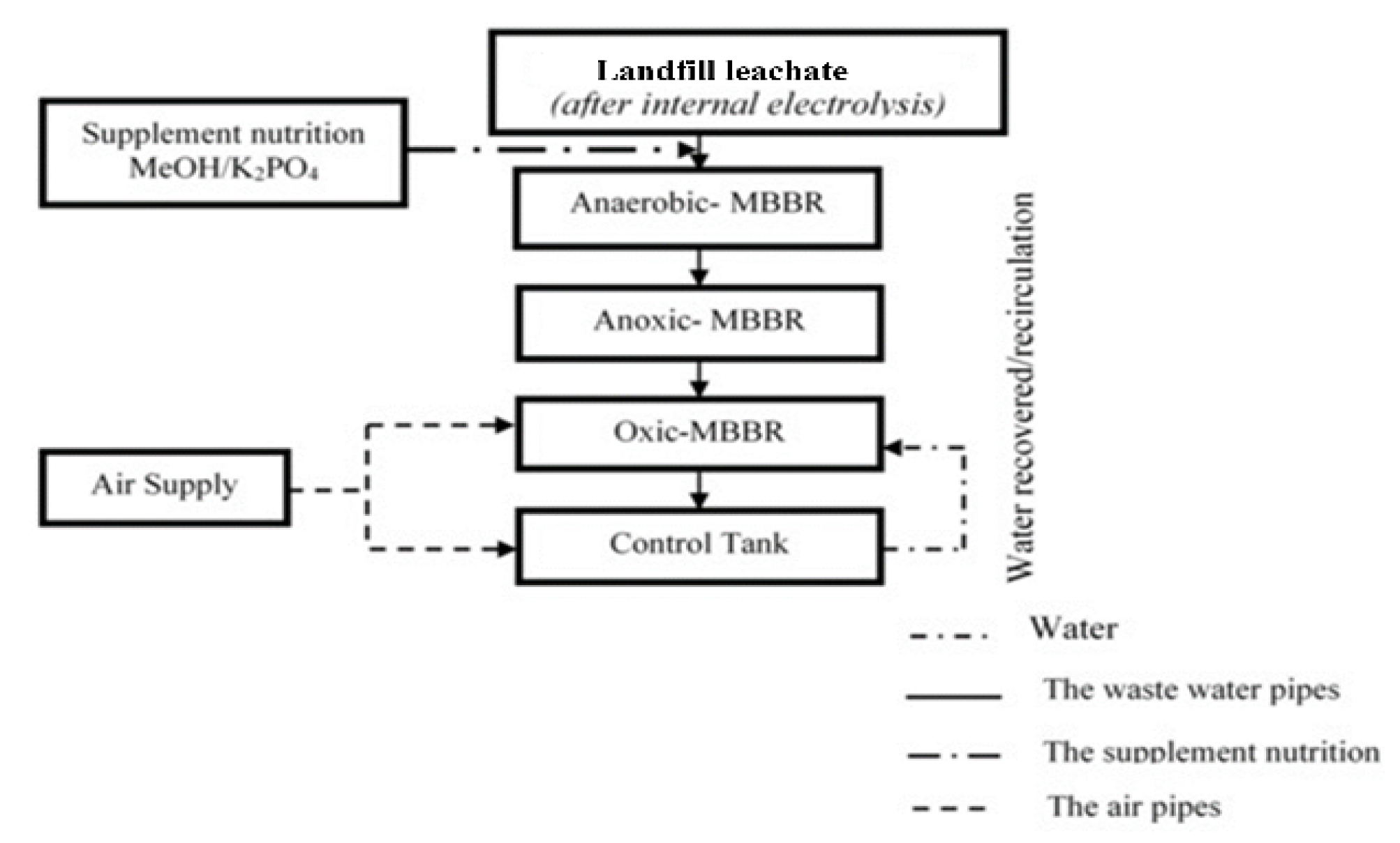
Figure 3.
(a) SEM image of iron powder before copper plating; (b) SEM image of Fe material under plating condition for 2 minutes, 5% CuSO4 solution.
Figure 3.
(a) SEM image of iron powder before copper plating; (b) SEM image of Fe material under plating condition for 2 minutes, 5% CuSO4 solution.
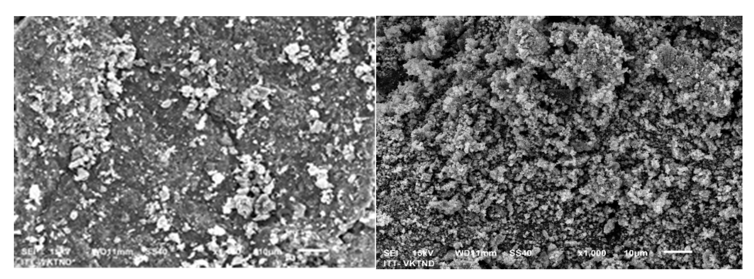
Figure 4.
(a) EDS spectrum of Fe powder; (b) EDS spectrum of Fe/Cu material.
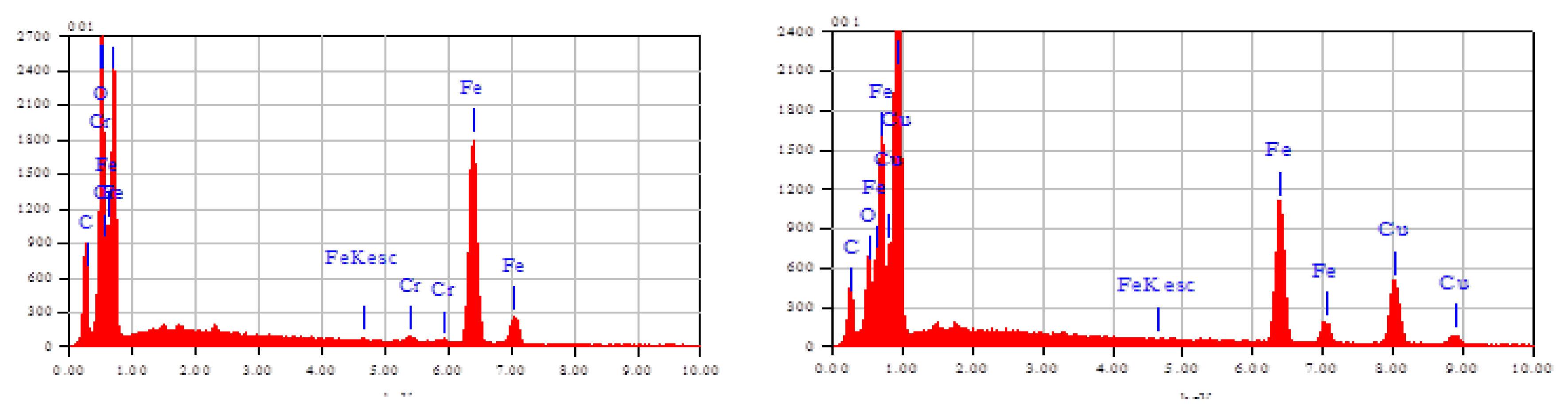
Figure 5.
XRD spectrums of material Fe and Fe/Cu.
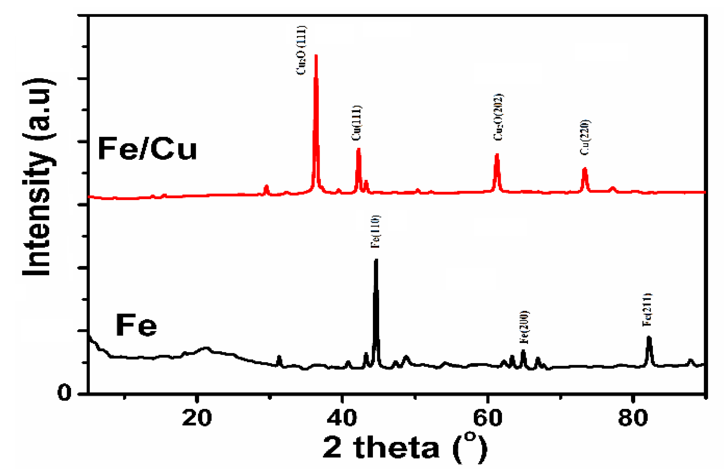
Figure 7.
Effect of treatment time on total N (a) and NH4+ content (b) by internal electrolysis method.
Figure 7.
Effect of treatment time on total N (a) and NH4+ content (b) by internal electrolysis method.
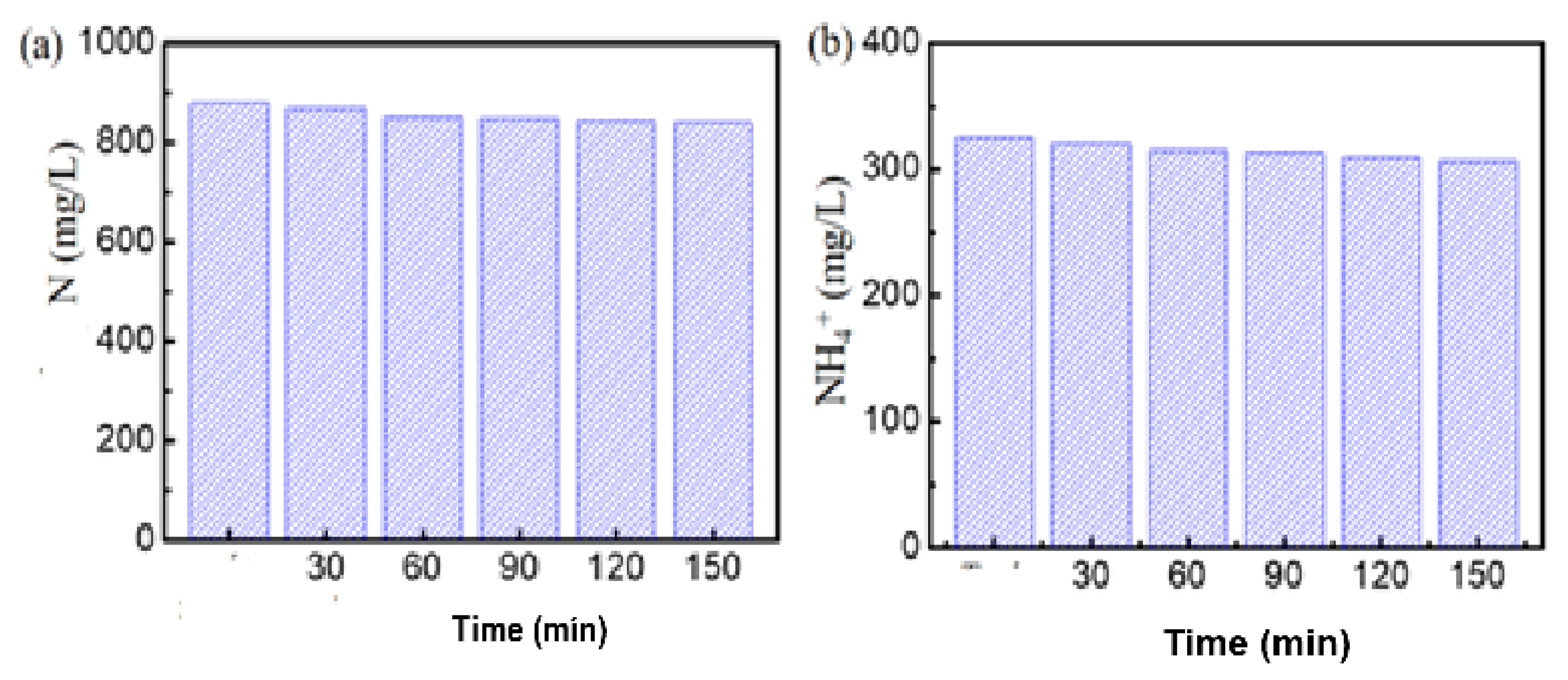
Figure 8.
P removal efficiency by internal electrolysis method.
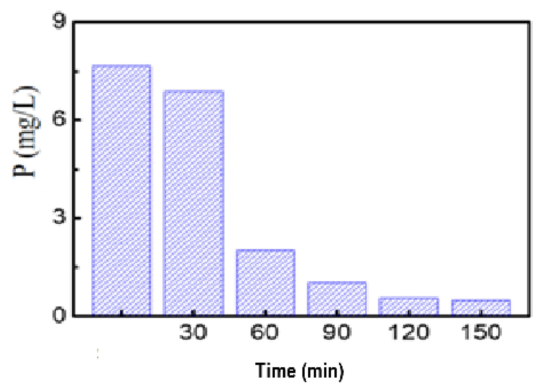
Figure 9.
Effect of pH on COD and color removal.
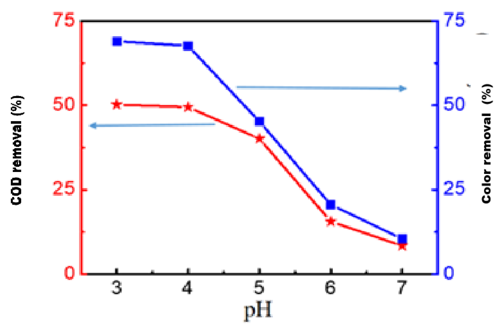
Figure 10.
Effect of pH on BOD5/COD value.
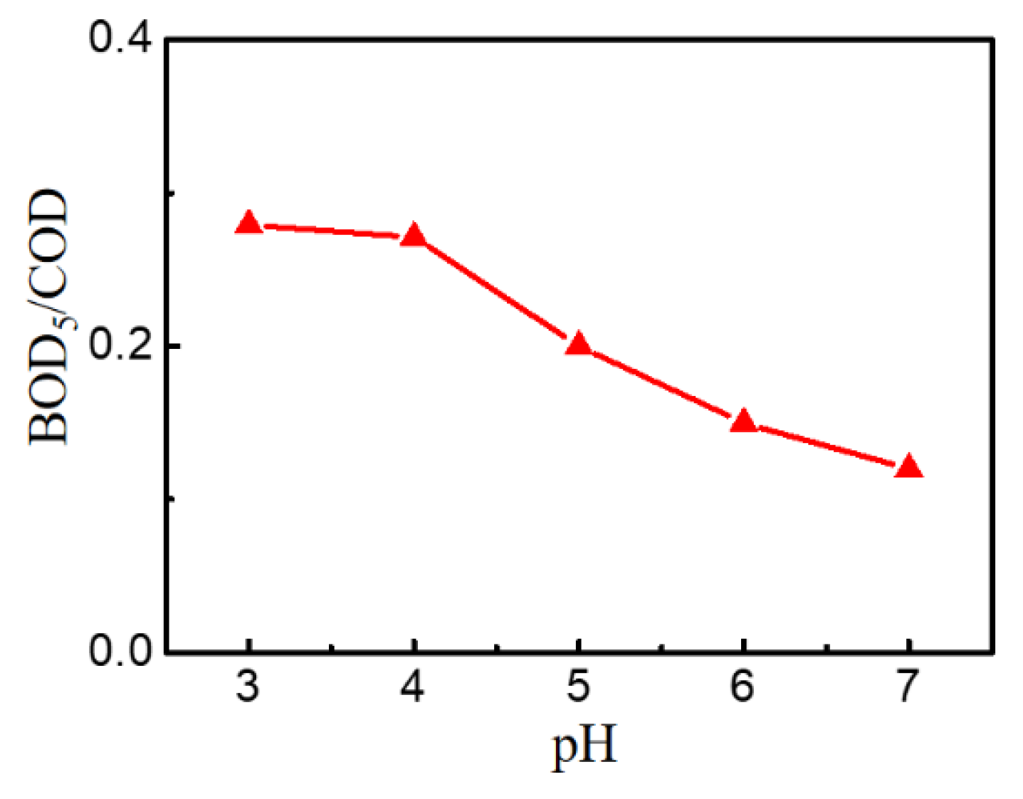
Figure 11.
Effect of Shaking Speed on COD removal rate.
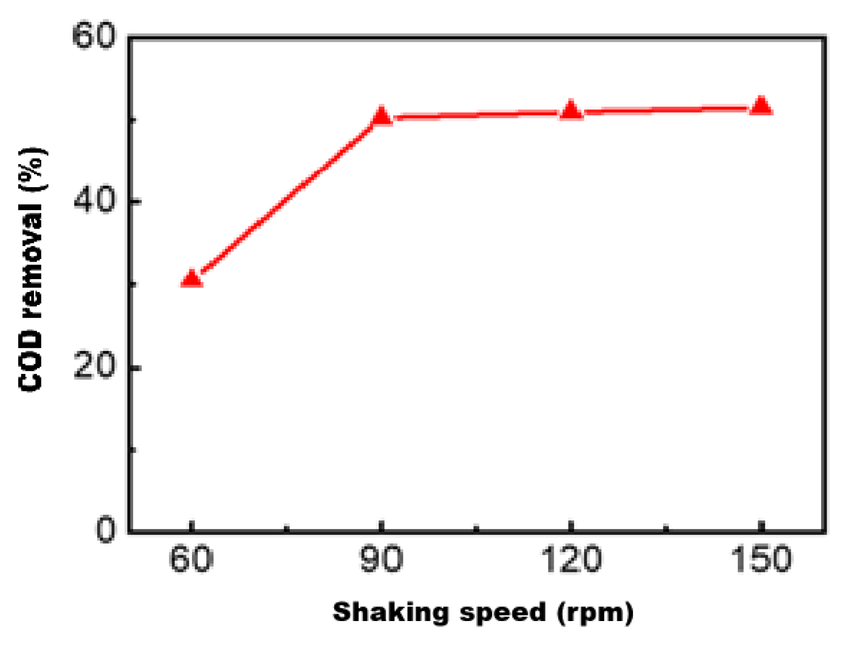
Figure 12.
Effect of shaking speed on BOD5/COD.
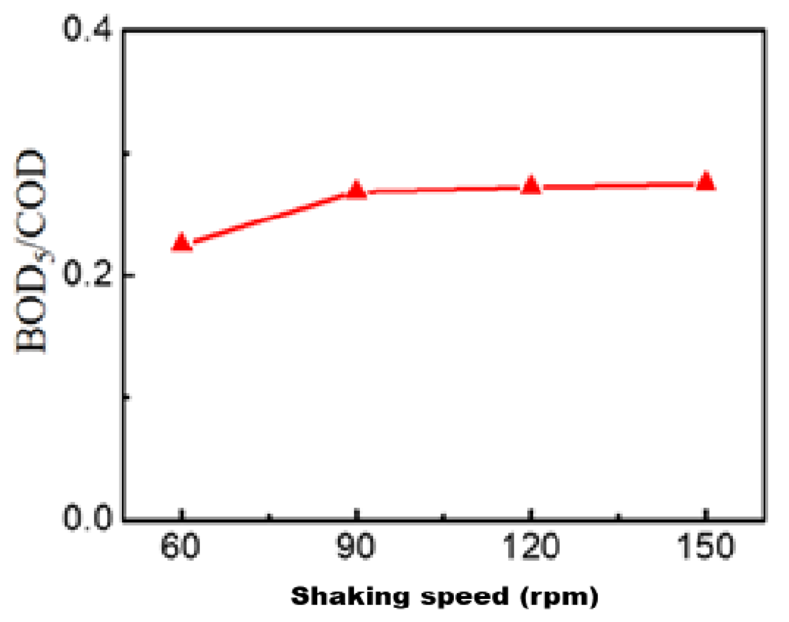
Figure 14.
Activated sludge development over time.
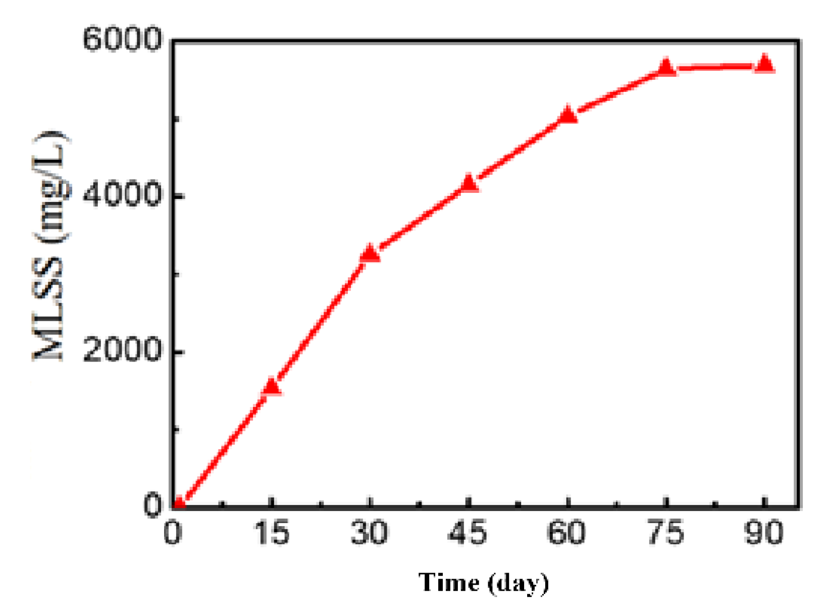
Figure 15.
COD removal efficiency over time.
| Numbers | Parameter | Unit | New leachate ≤1 year | Old leachate (1-3 years old) |
|---|---|---|---|---|
| 1 | pH | - | 4.89-6.41 | 7.81-7.89 |
| 2 | TDS | mg/L | 7.301-16.209 | 6.014-14.145 |
| 3 | Hardness | mg (CaCO3)/L | 5,833-9,677 | 1.26-1,867 |
| 4 | SS | mg/L | 1,760-4,311 | 169-243 |
| 5 | COD | mg (O2)/L | 38,533-65,333 | 1,092-2,507 |
| 6 | BOD | mg (O2)/L | 30,000-48,000 | 200-735 |
| 7 | VFA | mg/L | 17.677-25.2 | 26-33 |
| 8 | Total P | mg/L | 55.8-89.6 | 4.7-0.1 |
| 9 | Total N | mg/L | 977-1,800 | 515-1.874 |
| 10 | NH3 | mg/L | 781-1,764 | 512-1.874 |
| 11 | Organic nitrogen | mg/L | 196-470 | 3-4.8 |
| 12 | SO42- | mg/L | 1,400-1,590 | 7.5-14 |
| 13 | Cl- | mg/L | 3,960-4,500 | 7.5-14 |
| 14 | Ca2+ | mg/L | 1,670-2,736 | 60-80 |
| 15 | Mg2+ | mg/L | 404-687 | 297-381 |
| 16 | Pb | mg/L | 0.32-4.9 | - |
| 17 | Zn | mg/L | 93-202 | - |
| 18 | Al | mg/L | 0,04-0,5 | - |
| 19 | Mn | mg/L | 14.50-32.70 | - |
| 20 | Ni | mg/L | 2.21-8.02 | - |
| 21 | Total Cr6+ | mg/L | 0.04-0.05 | - |
| 22 | Cu | mg/L | 3.5-4.0 | - |
| 23 | Fe2+ | mg/L | 204-208 | 4.5-6.4 |
Table 4.
Results of analyzing EDS Fe and Fe/Cu samples.
| Samples | Elements | % Mass | % Atom |
|---|---|---|---|
| Fe | O | 8.95 | 25.55 |
| Fe | 91.05 | 74.45 | |
| Total | 100.00 | 100.00 | |
| Fe/Cu | O | 12.11 | 24.97 |
| Fe | 18.59 | 21.83 | |
| Cu | 69.30 | 53.20 | |
| Total | 100.00 | 100.00 |
Table 6.
Wastewater parameters through different treatment stages.
| Indicator | Before treatment | After Fe/Cu | After A2O - MBBR |
Fe-Cu & A2O-MBBR | QCVN 40: 2011/BTNMT (column B2) |
|
|---|---|---|---|---|---|---|
| After treatment | H% | |||||
| BOD5 mg/L | 250 | 258 | 44.8 | 44.8 | 85.2 | 50 |
| COD mg/l | 2140 | 1090 | 156 | 156 | 85.6 | 300 |
| Total N mg/L | 895 | 790 | 47.5 | 47.5 | 94.1 | 60 |
| Total P mg/L | 20 | 2.5 | 0.03 | 0.03 | 98.0 | 4.0 |
| -N mg/L | 335 | 301 | 9.7 | 9.7 | 96.7 | 25 |
| pH | 8.0-9.0 | 6.5 | 6.5 - 7.2 | 6.5 - 7.2 | - | 6.0 - 9.0 |
Disclaimer/Publisher’s Note: The statements, opinions and data contained in all publications are solely those of the individual author(s) and contributor(s) and not of MDPI and/or the editor(s). MDPI and/or the editor(s) disclaim responsibility for any injury to people or property resulting from any ideas, methods, instructions or products referred to in the content. |
© 2025 by the authors. Licensee MDPI, Basel, Switzerland. This article is an open access article distributed under the terms and conditions of the Creative Commons Attribution (CC BY) license (http://creativecommons.org/licenses/by/4.0/).
Copyright: This open access article is published under a Creative Commons CC BY 4.0 license, which permit the free download, distribution, and reuse, provided that the author and preprint are cited in any reuse.


