
Submitted:
06 December 2025
Posted:
08 December 2025
You are already at the latest version
Abstract
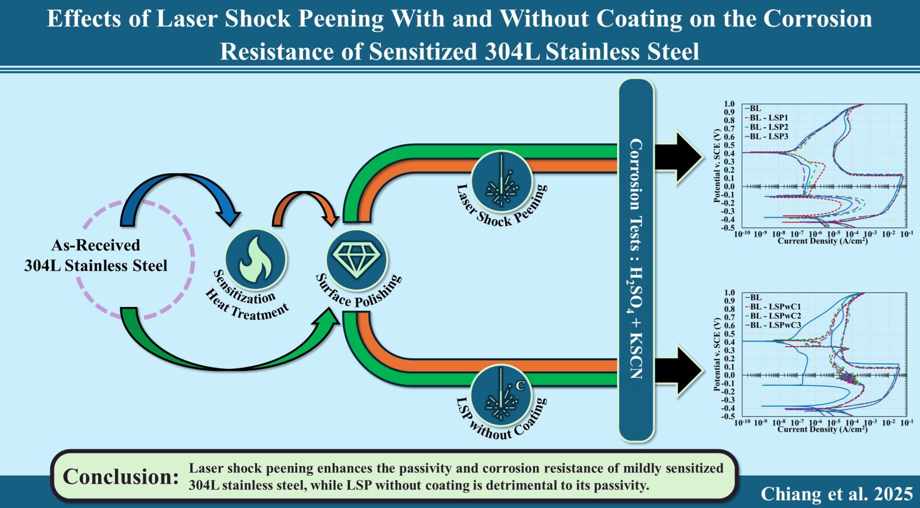
This study examined the effects of laser shock peening (LSP) and LSP without protective coating (LSPwC) on the microstructure and corrosion behavior of 304L stainless steel using cyclic polarization testing. LSP enhanced corrosion resistance under mild sensitization (650°C; 5hrs) by inducing compressive stress and increasing dislocation density, stabilizing the passive film. Limited improvement was observed under severe sensitization (650°C; 24 hrs). Deformation-induced martensite detected by XRD was attributed to mechanical polishing, not LSP. In contrast, LSPwC reduced corrosion resistance across all conditions due to Fe-rich surface oxides that impaired passivation.
Keywords:
stainless steel
; LSP
; LSPwC
; corrosion
; cyclic polarization
; passivity
; sensitization
1. Introduction
Austenitic stainless steels (SS) are widely recognized as one of the most versatile classes of materials due to their excellent mechanical properties, good formability, and high corrosion resistance. They are extensively used across a range of industries, with particularly critical applications in the nuclear sector. In nuclear reactor systems, these steels are commonly employed in piping, cladding, and structural components such as reactor core supports. They also serve a vital role in nuclear waste management as the primary material for fabricating nuclear storage canisters. These canisters form the backbone of dry cask storage systems (DCSS), which are designed to safely contain spent nuclear fuel (SNF) assemblies during their radioactive decay [1]. Among the available alloys, 304 and 316 stainless steels, along with their variants, are the most commonly used in DCSS applications.
A growing concern, however, is the potential for structural failure in these canisters due to material degradation. Localized corrosion and chloride-induced stress corrosion cracking (Cl-SCC) are well-documented failure mechanisms that can occur at the weldments of austenitic stainless steel DCSS canisters when exposed to chloride-rich aqueous environments [2,3,4,5]. Field inspections have confirmed that salt-bearing deposits can form on the surfaces of heated canisters near coastal storage sites [6,7,8,9]. As SNF decays, the canister surface temperature may fall within the threshold for deliquescence, depending on salt composition and ambient relative humidity [3,9,10,11,12].
Under these conditions, the resulting corrosive brine promotes pitting corrosion in stainless steel by forming a localized electrolyte enriched with chloride ions, which destabilize the passive film [12,13,14]. This susceptibility is further exacerbated if the alloy undergoes sensitization during fusion welding, as chromium depletion at grain boundaries caused by the precipitation of Cr-rich M23C6 carbides weakens the passive film near the heat-affected zone (HAZ) [15,16]. In addition, welding performed during the fabrication and repair of these canisters induces tensile residual stresses, as reported by Enos et al., further increasing the material’s susceptibility to both pitting and Cl-SCC [17,18].
In short, in-service 304L stainless steel canisters satisfy all the critical conditions for Cl-SCC: an aggressive environment, a susceptible microstructure, and the presence of tensile stress. This has prompted increased interest in surface modification techniques aimed at improving corrosion resistance in austenitic stainless steels. One promising method is laser shock peening (LSP), a non-contact surface treatment technique that uses high-energy, short-duration laser pulses to generate plasma-induced shock waves at the material surface. A transparent overlay is typically applied to confine the plasma, amplifying the pressure of the resulting shock wave as it propagates into the substrate. When this pressure exceeds the material’s Hugoniot Elastic Limit (HEL), it induces severe plastic deformation and generates a high density of dislocations in the near-surface region. These microstructural changes, including the development of deep compressive residual stresses and potential grain refinement, have been shown to improve the mechanical properties of austenitic stainless steels and enhance their corrosion resistance by stabilizing the passive film and reducing susceptibility to pitting and SCC.
This relationship between LSP-induced microstructural changes and improved corrosion resistance has been widely investigated in previous studies on austenitic stainless steels. Peyre et al. reported that LSP enhanced the corrosion resistance of 316L stainless steel by introducing compressive residual stresses that modified the alloy-defect interface and reduced the number of active sites for corrosion, thereby promoting a more stable passive film and improving resistance to both pitting and SCC in chloride-rich environments [19,20]. Similar results were observed by Lu et al. in 304 stainless steel, where LSP extended crack initiation times, increased pitting potentials, and reduced passive current densities [21,22]. These improvements were attributed to the combined effects of compressive residual stress and grain refinement, the latter of which enhances passive film stability through accelerated chromium diffusion and increases SCC resistance by promoting crack deflection or arrest at grain boundaries [21,22,23,24]. The extent of these benefits has been shown to increase with higher laser pulse densities due to greater residual compression and finer grain structures [21,25,26]. However, several studies have noted that these outcomes are not always consistent, underscoring the importance of optimizing LSP parameters to account for competing effects such as dislocation density, grain boundary characteristics, and the potential formation of deformation-induced martensite [27,28,29].
Building on previous research, this study evaluates the effects of laser shock peening, with and without a protective coating, on the corrosion resistance of sensitized 304L stainless steel in an oxidizing environment. While some prior work has explored the application of LSP without coating (LSPwC) on 304L stainless steel in chloride-rich environments [25,30,31,32], fewer studies have evaluated its performance in more oxidizing media like sulfuric acid. These environments offer greater sensitivity to changes in passivity, enabling a clearer assessment of LSP’s influence on passive film stability. It is hypothesized that LSP will enhance the corrosion resistance of 304L stainless steel by improving passive film stability through the introduction of compressive residual stresses and grain refinement. However, these beneficial effects may not be sufficient to fully counteract the detrimental impact of sensitization. In the case of LSPwC, performance is expected to decline due to surface oxidation caused by plasma-induced heating, which may impair passivity. These adverse effects may be mitigated at lower pulse energies where thermal influence is reduced.
2. Materials and Methods
2.1. Material
Type 304L austenitic stainless steel plates, with a nominal thickness of 3 mm, were supplied by Sandia National Laboratories. To achieve chemical homogeneity and dissolve pre-existing carbide precipitates, the hot-rolled plates were solution annealed at 1080 °C for 2hr and subsequently water quenched by the manufacturer. The bulk chemical composition, as provided by the supplier, is listed in Table 1.
2.2. Specimen Preparation
The stainless steel plates were sectioned into 30mm x 30mm square coupons using electrical discharge machining (EDM) to minimize thermal distortion and residual stress. All specimens were mechanically polished with silicon carbide (SiC) abrasive papers in sequential grit sizes ranging from 180 to 600grit, producing a uniform surface finish. These initial specimens are referred to as the as-polished baseline (BL). To evaluate the effect of sensitization on corrosion behavior, two thermal exposure regimes were applied to separate sets of specimens. Sensitization was induced through isothermal heat treatment at 650 °C in ambient atmosphere for either 5hrs (designated SEN1) or 24hrs (designated SEN2), followed by air cooling. Table 2 summarizes the specimen designations and corresponding processing parameters.
2.3. Laser Shock Peening
Laser shock peening (LSP) was performed at the University of Cincinnati using a Continuum Powerlite Plus system equipped with a Q-switched Nd:YAG infrared laser (λ = 1064 nm), operating at 10Hz with a maximum pulse energy of 3J. The laser beam was focused to a 2mm diameter spot. Six LSP conditions were investigated to evaluate the effects of varying laser energy and surface protection on corrosion behavior. These conditions consisted of three energy levels applied under two surface states: with (LSP) and without (LSPwC) a sacrificial coating. A summary of the key processing parameters is provided in Table 3, and the experimental setup and peening patterns are illustrated in Figure 1.
Each LSP treatment targeted a 20mm x 20mm area and employed a 50% spot overlap strategy executed through four sequential passes to ensure uniform coverage and consistent stress distribution (Figure 1-LSP). The laser path was precisely controlled by a Fanuc Robotics LR Mate 200iC system, ensuring accurate spatial alignment between passes. A deviated spot pattern was used in each sequence to minimize tearing of the protective layer and to promote full-area coverage. For the LSPwC conditions, a similar procedure was followed; however, a direct 50% spot overlap was applied in a single pass (Figure 1-LSPwC).
Each LSP treatment targeted a 20mm x 20mm area and employed a 50% spot overlap strategy executed through four sequential passes to ensure uniform coverage and consistent stress distribution. The laser path was precisely controlled by a Fanuc Robotics LR Mate 200iC system, ensuring accurate spatial alignment between passes. A deviated spot pattern was used in each sequence to minimize tearing of the protective layer and to promote full-area coverage. For the LSPwC conditions, the 20mm x 20mm area was treated using a single pass with a direct 50% spot overlap, eliminating the need for multiple overlapping sequences.
For the coated LSP conditions, a 130μm thick layer of 3M 471 black vinyl tape was applied to the specimen surface to reduce thermal effects and prevent surface ablation. In contrast, LSPwC treatments were performed directly on the polished surface, allowing evaluation of laser-induced effects in the absence of a sacrificial layer. In both cases, a 1mm thick water layer served as the transparent confining medium, amplifying the shock wave by constraining the plasma plume (Figure 1A) [33,34]. This process is known to induce severe plastic deformation (SPD) and deep compressive residual stresses near the surface.
2.4. Residaul Stress Depth Profile
Residual stress (RS) and diffraction peak full width at half maximum (FWHM) were measured in two orthogonal directions (0° and 90°) using a Proto LXRD stress measurement system equipped with a single-axis goniometer operating in Ω geometry. Measurements were performed using the sin2ψ method with electrolytic layer removal. Prior to each run, the system was calibrated using certified 316L and carbon steel standards under Mn-Kα and Cr-Kα radiation, respectively, following ASTM E915-19 [35]. Depth profiling was conducted via sequential electropolishing using a solution of 87.5 vol% methanol and 12.5 vol% H2SO4. Material was removed in 30μm increments up to 150μm for high-resolution mapping near the surface, followed by 50μm steps to 500μm, 100μm steps to 1100μm, and 200μm steps to a final depth of 1500μm. Strain gradient and layer removal corrections were applied in accordance with SAE J784a [36]. LXRD measurement parameters are summarized in Table 4.
2.5. Cyclic Polarization Test
The degree of sensitization (DOS) and susceptibility to corrosion were quantified using double-loop electrochemical potentiodynamic reactivation (DLEPR), following ASTM G108-94 [37]. Tests were conducted using a Gamry Reference 600 potentiostat in a conventional three-electrode paracell configuration, with a graphite counter electrode, a reference saturated calomel electrode (SCE), and the target specimen as the working electrode. The test solution consisted of 0.5M H2SO4 + 0.05M KSCN at 23 °C. Prior to each scan, the electrolyte was deaerated for 1hr using high-purity argon gas, followed by a 1hr stabilization period to reach a near steady-state open circuit potential (OCP). Cyclic polarization scans were carried out at a rate of 0.56 mV/s, sweeping the potential from -500mV to +1000mV (SCE) and then back to -500mV.
2.6. Surface Optical Profile
Surface roughness was measured via white light vertical scanning interferometry using a Veeco Wyko NT1100 system. A minimum of three scans were taken at randomly distributed locations across each specimen to ensure statistical consistency. Roughness parameters were extracted from the 3D profiles to assess surface modifications resulting from the LSP treatment.
2.7. Scanning Electron Microscopy
Microstructural analysis was conducted using an FEI Apreo field emission scanning electron microscope (SEM) equipped with a solid-state detector for energy dispersive X-ray spectroscopy (EDS). Imaging was carried out in both secondary electron (SE) and backscattered electron (BSE) modes under an accelerating voltage of 20kV, a beam current of 3.2nA, and a working distance of 10mm. In BSE imaging, channeling contrast predominated due to the similar atomic numbers of the alloying elements in 304L stainless steel, which limited compositional differentiation.
2.8. X-Ray Diffraction (XRD)
Phase analysis of the 304L stainless steel specimens was conducted using a Philips X’Pert Modular Powder Diffractometer with Cu-Kα radiation (λ = 1.5406 Å) operated in θ–2θ geometry. Diffraction patterns were collected over a 2θ range of 30°–110° with a step size of 0.02° and a dwell time of 0.5s per step. The resulting data were used to identify phase constituents and detect possible deformation-induced transformations.
3. Results
3.1. Microstructure Analysis and Surface Profile
Figure 2 presents SEM secondary electron (SE) micrographs of as-polished 304L stainless steel in three conditions: the baseline (BL), and specimens sensitized at 650 °C for 5hrs (SEN1) and 24hrs (SEN2). Compared to BL, both SEN1 and SEN2 exhibit chromium-rich carbide precipitation along the grain boundaries, as confirmed by EDS analysis, with the extent of precipitation more pronounced in SEN2 due to prolonged exposure. This carbide formation is consistent with established literature and is linked to localized chromium depletion that weakens the passive film and increases susceptibility to intergranular corrosion (IGC) [16,38]. As a result, sensitized specimens are expected to exhibit higher degrees of susceptibility (DOS), especially in SEN2.
SEM imaging of the 304L stainless steel specimens revealed a predominantly equiaxed austenitic microstructure, with an average grain size of 16.25μm ± 1.33μm (ASTM 9), measured using the line intercept method in ImageJ. No evidence of grain coarsening was observed across the sensitization conditions, indicating that the applied thermal exposures had minimal effect on the bulk grain morphology. The microstructure showed no visible presence of secondary phases such as martensite or delta ferrite. However, XRD analysis of the as-polished surface (Figure 3A) revealed additional peaks corresponding to a body-centered cubic (BCC) phase, likely deformation-induced martensite. After electropolishing, these peaks disappeared (Figure 3B), confirming that the martensitic phase was confined to the mechanically worked surface layer generated during specimen preparation.
Following these results, XRD analysis of the laser-treated specimens revealed only minor phase changes related to surface modification. The LSP-treated samples remained predominantly austenitic, with a slight increase in deformation-induced martensite (Figure 4). However, the martensitic phase was also detected in the BL specimen, suggesting that most of its formation likely resulted from mechanical polishing rather than laser processing. Table 5 summarizes the estimated martensite content after each treatment, calculated in accordance with ASTM E975-13 using the (200)α’ and (220)γ peaks for comparison [39]. In the LSPwC specimens, additional peaks corresponding to Fe-oxide phases appeared in the XRD scan (Figure 4-LSPwC). These oxides are attributed to surface oxidation caused by laser ablation in the absence of a sacrificial coating.
Figure 5 presents the 3D surface profiles of the BL specimens before and after LSP treatment. Surface roughness measurements revealed a notable increase in both roughness average (Ra) and average maximum height (Rz) compared to the untreated baseline. The BL specimen exhibited a smooth surface with minimal topographic variation, consistent with standard mechanical polishing. In contrast, all LSP-treated conditions showed elevated roughness values that increased slightly with pulse energy. This increase is attributed to localized plastic deformation and surface uplift caused by high-intensity shockwave impacts during peening.
As shown in Table 6, surface residual stress measurements using LXRD indicated that all specimen conditions were in a compressive stress state, with the magnitude increasing with laser pulse energy. The BL condition exhibited low surface compression attributed to mechanical polishing, which rapidly relaxed to a near-zero state following removal of the top 30μm by electropolishing. This near-neutral stress profile remained consistent throughout the measured depth in the BL specimen, as depicted in Figure 7A. In contrast, the LSP-treated specimens showed both greater compressive stress and increased penetration depth, with values scaling with laser energy. The compressive stress extended to approximately 600μm, gradually decreasing with depth (Figure 7A). Depth profiling of the martensitic phase was not possible, as the low-intensity martensitic peak disappeared after the initial electrolytic polish. Moreover, this low signal further confirms that only a small fraction of austenite had transformed to martensite overall.
Figure 6.
Martensite peak from LXRD disappearing following EP.
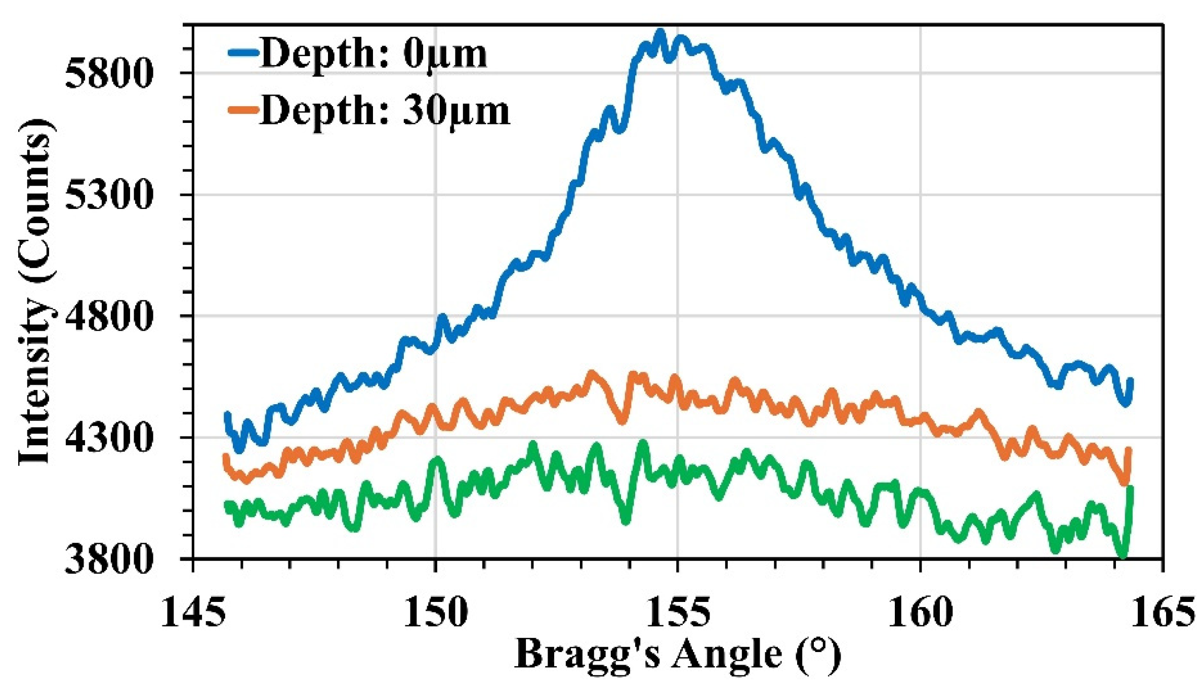
Figure 7.
(A) Residual stress and (B) FWHM depth profiles of 304L stainless steel specimens treated with LSP at varying pulse energies (0J, 1J, 1.5J, and 3J).
Figure 7.
(A) Residual stress and (B) FWHM depth profiles of 304L stainless steel specimens treated with LSP at varying pulse energies (0J, 1J, 1.5J, and 3J).
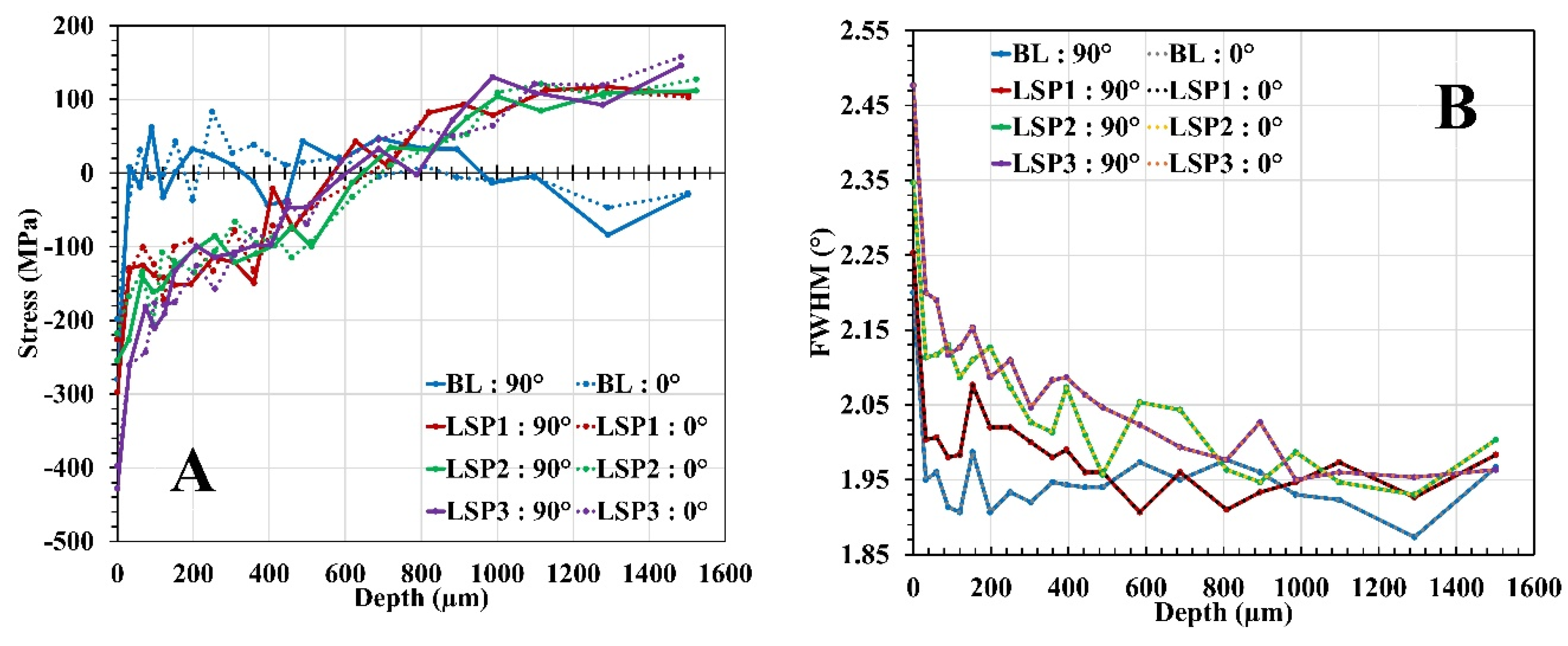
FWHM analysis of the diffraction peaks provided insight into the plastic strain distribution induced by LSP and further supported the residual stress depth profiling results. The BL specimen exhibited narrow and consistent FWHM values throughout the measured depth, apart from slight broadening at the surface due to minor lattice distortion from mechanical polishing (Figure 7B). In contrast, the LSP-treated specimens exhibited elevated FWHM near the surface, with greater peak broadening observed at higher laser intensities. This increase is attributed to a higher dislocation density and localized lattice strain generated by shock peening. Similar to the residual stress profiles, FWHM values decreased progressively with depth, approaching baseline levels near 650μm. These findings confirm that LSP introduces significant near-surface strain and dislocation structures that contribute to the observed compressive stress field.
3.2. Cyclic Polarization
Cyclic potentiodynamic polarization tests were performed in a 0.5M H2SO4 + 0.05M KSCN solution to assess the influence of laser shock peening (LSP), both with and without a sacrificial coating (LSPwC), on the corrosion behavior of sensitized 304L stainless steel. The specimen matrix included an as-polished baseline (BL) and two sensitized conditions: SEN1 (650 °C for 5hrs) and SEN2 (650 °C for 24hrs), each evaluated in untreated, LSP-treated, and LSPwC-treated states across varying laser intensities. As shown in Figure 8 and Figure 10, all specimens exhibited typical active-passive behavior, characterized by anodic activation, a passive plateau, and transpassive breakdown. Key electrochemical parameters were extracted from the polarization curves and are summarized in Table 7. Figure 9 presents representative SEM images showing surface degradation for the BL, SEN1, and SEN2 conditions following polarization testing.
Figure 9.
SEM SE micrographs of as-polished 304L stainless steel in three conditions: (BL) baseline, (SEN1) sensitized for 5hrs, and (SEN2) sensitized for 24hrs after electrochemical testing.
Figure 9.
SEM SE micrographs of as-polished 304L stainless steel in three conditions: (BL) baseline, (SEN1) sensitized for 5hrs, and (SEN2) sensitized for 24hrs after electrochemical testing.
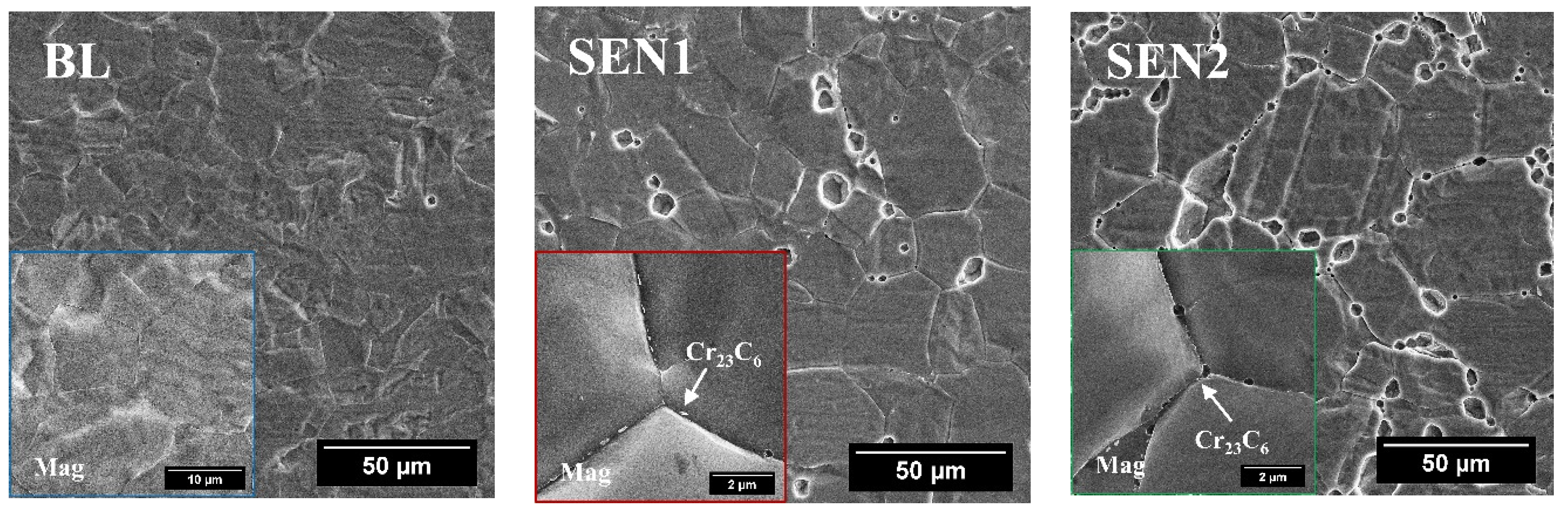
Figure 10.
Cyclic polarization curves for 304L stainless steel specimens (BL, SEN1, and SEN2) subjected to LSP and LSPwC, exposed to 0.5M H2SO4 + 0.05M KSCN.
Figure 10.
Cyclic polarization curves for 304L stainless steel specimens (BL, SEN1, and SEN2) subjected to LSP and LSPwC, exposed to 0.5M H2SO4 + 0.05M KSCN.
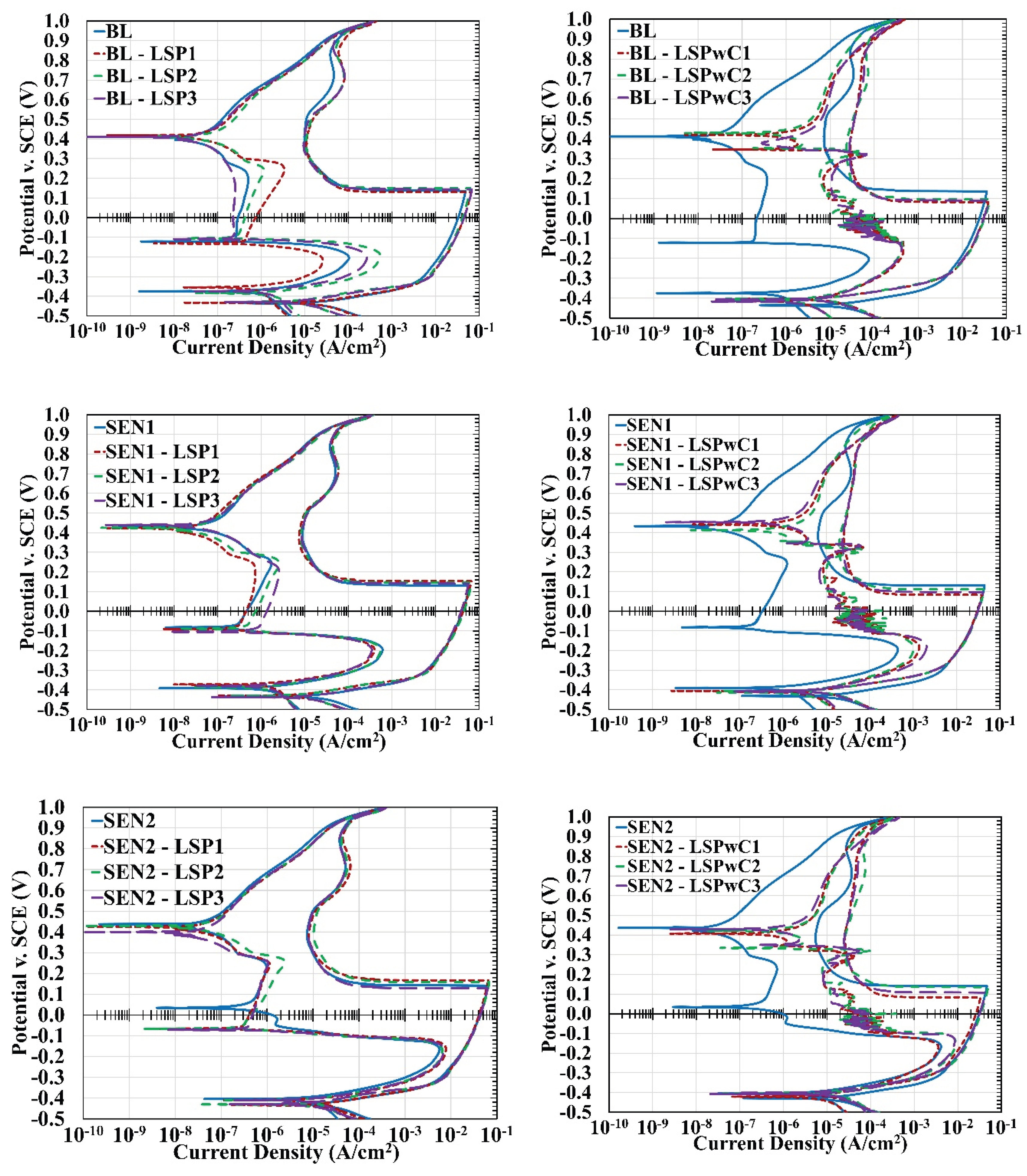
To quantify the effects of sensitization and surface treatment, the degree of sensitization (%DOS) was calculated for each specimen condition. The sulfuric acid and thiocyanate environment is highly sensitive to changes in passive film integrity, making it well-suited for evaluating corrosion susceptibility in austenitic stainless steels. %DOS is defined as the ratio of the reactivation current density (Ir) to the critical current density (Ic), as shown in Equation 1. A lower Ir relative to Ic indicates a more stable passive film, as reactivation during the reverse scan is more effectively suppressed. Accordingly, lower %DOS values correspond to improved passivation and decreased susceptibility to intergranular corrosion (IGC). As a reference, %DOS values are commonly interpreted in four ranges: values below 1% indicate negligible susceptibility; 1–5% reflects slight susceptibility; 5–30% indicates moderate susceptibility; and values above 30% correspond to severe susceptibility.
This study confirms that %DOS varied significantly across the untreated specimen conditions, increasing with longer sensitization times (Figure 8). The BL specimen exhibited a low %DOS of 0.21%, indicating minimal susceptibility to IGC and a stable passive film. Post-experimental SEM analysis (Figure 9-BL) showed uniform surface corrosion with a step-like topography and minimal pitting, consistent with effective passivation. After sensitization at 650 °C for 5hrs, the SEN1 specimen exhibited a %DOS of 1.01%, reflecting slight susceptibility due to localized chromium depletion from carbide precipitation. SEM images (Figure 9-SEN1) revealed features consistent with partial sensitization, including a mixture of step-like regions, shallow pits, and early trenching at grain boundaries. Extending the exposure to 24hrs further increased the %DOS to 8.86%, indicating moderate IGC susceptibility and greater passive film degradation. The SEN2 surface (Figure 9-SEN2) exhibited more pronounced intergranular attack, deeper trenches, and increased pitting. These observations align with the expected progression of chromium carbide formation and chromium depletion at grain boundaries during prolonged sensitization heat treatment.
Compared to their untreated counterparts, the LSP-treated specimens exhibited measurable changes in corrosion response across both baseline and sensitized conditions (Figure 10). For the BL specimens, low-energy LSP (LSP1) reduced %DOS from 0.21% to 0.04%, indicating improved passivation likely due to the introduction of compressive residual stress and potential surface grain refinement. At moderate (LSP2) and high (LSP3) energy levels, %DOS increased slightly to 0.87% and 0.39%, respectively, suggesting diminishing returns or minor disruption to film stability, potentially linked to increased surface roughness and dislocation density. Despite these increases, both conditions remained below the 1% threshold, indicating negligible susceptibility. In contrast, BL specimens treated without a protective coating (LSPwC) exhibited higher %DOS values exceeding 1%, placing them in the slightly susceptible range. This degradation is likely due to the surface oxidation and ablation introduced from laser exposure, which may compromise passive film integrity and promote localized corrosion.
For the SEN1 condition, LSP improved corrosion resistance relative to the untreated specimen (Figure 10). LSP1 and LSP3 reduced %DOS to 0.61%, while LSP2 yielded a slightly higher value of 0.82%, suggesting that LSP partially mitigated the sensitization effects through the introduction of compressive residual stress and possibly enhanced chromium mobility toward the surface. This may have helped counteract chromium depletion at grain boundaries caused by carbide precipitation. In contrast, the LSPwC specimens exhibited increased %DOS values following surface treatment, though susceptibility remained low in all cases. The higher %DOS suggests that macrostructural defects, such as the formation of unstable iron oxides, played a dominant role in the corrosion behavior. The oxide layer likely compounded the weakened passivity by further localizing the electrochemical attack leading to increased pitting and IGC.
In the more heavily sensitized SEN2 condition, LSP treatment slightly worsened corrosion performance, with %DOS values increasing to 11.99% (LSP1), 9.66% (LSP2), and 11.32% (LSP3). These results indicate that under the current processing parameters, LSP is ineffective at restoring passivity once extensive grain boundary chromium depletion has occurred. LSPwC-treated specimens performed even worse, further supporting the hypothesis that surface oxidation caused by unprotected laser exposure significantly degrades corrosion resistance.
Overall, trends in %DOS demonstrate that while LSP can modestly improve passivity in mildly sensitized stainless steel, its effectiveness diminishes under moderate sensitization, particularly when no protective coating is used. To further evaluate corrosion performance, changes in corrosion potential (ΔEcorr) and corrosion current density (ΔIcorr) were analyzed to assess the material’s corrosion tendency and passive film stability across treatment conditions.
ΔEcorr, defined as the difference between the corrosion potentials obtained during the forward (Ecorr) and reverse (Ecorr′) scans, reflects the stability of the passive film, with more positive ΔEcorr values suggesting better repassivation behavior. Similarly, ΔIcorr represents the change in corrosion current density between the forward (Icorr) and reverse (Icorr′) scans, where a negative ΔIcorr signifies reduced anodic activity due to stable passivity, while a positive ΔIcorr denotes increased active corrosion resulting from limited repassivation.
This relationship is clearly observed when comparing the untreated 304L stainless steel specimens. As shown in Table 7, the BL condition exhibited the most favorable electrochemical response, with a ΔEcorr of +60.6 mV and a ΔIcorr of −25.92 μA/cm2, indicating strong repassivation and a stable passive film. In contrast, the sensitized specimens exhibited progressively poorer performance with increasing thermal exposure. The SEN1 specimen showed a lower ΔEcorr (+41.1 mV) and a less negative ΔIcorr (−21.52 μA/cm2), while the SEN2 specimen demonstrated a further decline in corrosion performance, with a ΔEcorr of +24.8 mV and a ΔIcorr of −10.43 μA/cm2. These results confirm the detrimental effect of chromium carbide precipitation on passive film stability, arising from chromium depletion at grain boundaries during sensitization.
For the LSP-treated surfaces, the results show improvements in both ΔEcorr and ΔIcorr for the BL and SEN1 conditions. In the BL specimens, the LSP1 treatment produced the most beneficial response, yielding a ΔEcorr of +78.1 mV and a ΔIcorr of –22.64 μA/cm2, indicative of enhanced repassivation behavior. This improvement is attributed to the introduction of compressive residual stress, which promote passive film stability. However, at higher pulse energies, corrosion performance declined, as reflected by lower ΔEcorr values and less negative ΔIcorr values. This reduction in stability is likely associated with increased surface roughness, which can disrupt passive film continuity.
In the SEN1 condition, LSP treatment remained advantageous across all energy levels, with a modest increase in ΔEcorr, suggesting that LSP mitigated the adverse effects of chromium depletion by promoting passive film recovery. Conversely, in the SEN2 condition, passivation weakened following LSP, implying that in severely sensitized 304L stainless steel, the extent of chromium depletion from the carbide precipitation may exceed the restorative capacity of LSP. Further optimization of LSP parameters may be necessary to achieve corrosion improvement under such conditions.
Compared with their LSP-treated counterparts, the LSPwC specimens consistently exhibited inferior corrosion performance across all base conditions. The slightly negative ΔEcorr values indicate that surface oxidation hindered the formation of a stable passive film. Moreover, the ΔIcorr values remained small and less negative, suggesting persistent anodic activity through an unprotective Fe-oxide layer that promotes localized corrosion. These findings underscore the detrimental effects of uncoated laser peening and highlight the essential role of a sacrificial confining layer in maintaining surface integrity and corrosion resistance during LSP processing.
Although parameters such as %DOS ΔEcorr, and ΔIcorr offer valuable insight into a material’s passive behavior, they do not directly quantify its degradation rate in a defined environment. To address this limitation, the corrosion rate (CR) was calculated using Faraday’s law, as shown in Equation 2, based on the measured Icorr values and the following constants: a corrosion rate constant (K) of 1.288 x 10⁵ milli-inches or 3272 cm, an equivalent weight (EW) of 25.12, a density (d) of 7.87 g/cm3, and a surface area (A) of 1.00 cm2 [40].
For the BL condition, the untreated specimen exhibited a CR of 0.718 mmpy. This value decreased substantially following LSP, with BL-LSP2 and BL-LSP3 showing the lowest rates at 0.195 and 0.218 mmpy, respectively. The improvement is attributed to the introduction of compressive residual stress and potential grain refinement, both of which likely contributed to reduced alloy dissolution. Similar reductions were observed in the SEN1 and SEN2 conditions after LSP treatment, demonstrating that the technique remains effective even in sensitized microstructures. LSPwC-treated specimens also exhibited lower CR values across all base conditions; however, the similar rates suggest that this effect may be a result of the laser-induced surface oxide layer that temporarily limits electrolyte access. In summary, these results confirm that LSP enhances the corrosion resistance of 304L stainless steel by reducing degradation rates and improving passive film performance.
4. Discussion
4.1. Effect of Laser Shock Peening on 304L Stainless Steel
Laser shock peening (LSP) was applied to 304L stainless steel under baseline (BL) and sensitized (SEN1, SEN2) conditions using varying pulse densities (LSP1, LSP2, LSP3). The objective was to assess whether LSP could enhance corrosion resistance by inducing compressive residual stress and improving passive film stability through increased dislocation density. A secondary aim was to determine whether higher peening intensities might promote deformation-induced martensite, which is known to compromise corrosion performance [28,41,42,43].
In austenitic stainless steels, severe plastic deformation (SPD) is typically accommodated by deformation twinning and dislocation slip, with the dominant mechanism governed by both stacking fault energy (SFE) and strain rate. For low-SFE alloys such as 304L, twinning is energetically favored due to the suppression of dislocation cross-slip. Chen et al. reported that martensitic transformation tends to occur at lower strain rates (10-103 s-1), while twinning dominates at rates above 104 s-1 [44]. Given that LSP induces strain rates on the order of 105 to 106 s-1, deformation twinning is expected to be the prevailing mechanism that occurs under these conditions [45].
XRD analysis supported this expectation, showing that LSP-treated specimens retained a predominantly austenitic microstructure with low-intensity martensitic peaks confined to the near-surface region. Similar peaks were observed in the as-polished untreated specimens, and in both cases, they disappeared after electropolishing. This suggests that the martensitic phase likely formed due to low strain-rate deformation during mechanical polishing, rather than as a result of the LSP surface treatment. These findings are consistent with previous studies reporting that LSP promotes twinning rather than martensitic transformation in low-SFE stainless steels [24,46,47].
Residual stress and FWHM depth profiling confirmed that LSP introduced a substantial compressive stress field in the near-surface region of 304L stainless steel. In the BL specimens, only shallow compressive stress was observed from mechanical polishing, which was fully relieved after electrolytic removal of the top 30μm. By contrast, LSP-treated specimens retained significant compressive stress to depths approaching 600μm. Higher pulse densities resulted in greater stress magnitudes, deeper penetration, and increased dislocation density. This sustained subsurface compression is critical for improving corrosion resistance as it has been shown to help suppress crack initiation, reduce pit propagation, and decrease passive film degradation.
Several studies have confirmed that compressive residual stress, along with microstructural changes such as grain refinement, significantly enhances the corrosion resistance of austenitic stainless steels. Lu et al. demonstrated that LSP delayed crack initiation and reduced pit growth in 304 stainless steel by stabilizing the passive film through grain refinement and suppressing crack propagation via compressive stress [21,22]. Guan et al. similarly reported improved pitting resistance in 304L stainless steel, citing increased pitting potential, reduced metastable pit formation, and enhanced passive film quality attributed to the combined effects of surface compression and refined microstructure [24]. Brandal et al. observed a 65% increase in time-to-failure for LSP-treated 304 stainless steel in boiling MgCl2, attributing this improvement to high surface compression which increased the electron work function and strengthened passivation behavior [27].
The improvements reported in these studies are mirrored in the present investigation’s electrochemical results. For the mildly sensitized SEN1 condition, LSP significantly improved all measured metrics. The %DOS decreased to below 1%, indicating a transition from slight to negligible susceptibility, while favorable shifts in ΔEcorr suggested enhanced passive film stability and repassivation behavior. A corresponding reduction in corrosion rate further confirmed the effectiveness of LSP in reducing material degradation.
In contrast, the heavily sensitized SEN2 specimens showed limited recovery. %DOS and ΔIcorr remained elevated, indicating poor passivation, although a modest decrease in corrosion rate suggests that LSP may still provide some surface protection. For the BL condition, LSP consistently reduced corrosion rate, but improvements in passivation metrics were less consistent, particularly at higher peening intensities. This could reflect tradeoffs associated with increased surface roughness or dislocation density.
Overall, these findings demonstrate that LSP is generally effective in mitigating corrosion in 304L stainless steel, especially under mild sensitization, though its capacity to restore passivity diminishes in more severely degraded microstructures. Further optimization of LSP parameters may be necessary to extend corrosion protection to more severely sensitized or structurally degraded materials.
4.2. Effect of Laser Shock Peening Without Protective Coating on 304L Stainless Steel
Laser shock peening without a protective coating (LSPwC) was applied to 304L stainless steel under baseline (BL) and sensitized (SEN1, SEN2) conditions using varying pulse densities (LSPwC1, LSPwC2, LSPwC3). This part of the study aimed to evaluate how the absence of a sacrificial overlay during LSP influences corrosion behavior by modifying surface chemistry. Specifically, it assessed whether the compressive stresses induced by LSPwC could still enhance corrosion resistance, despite the additional surface oxidation and potential thermal effects caused by direct laser–material interaction. To maintain consistency with the LSP-treated specimens, the processing strategy did not take advantage of the higher overlap efficiency typically achievable with LSPwC.
In this study, the LSPwC-treated specimens across all base conditions exhibited a consistent decline in corrosion performance compared to their LSP counterparts. This was evidenced by a shift toward more negative ΔEcorr, more positive ΔIcorr, and higher %DOS values. These electrochemical trends suggest that direct laser exposure altered the surface composition by promoting Fe-oxide formation, which compromised passive film development. As a result, the corrosion resistance of 304L stainless steel was reduced, likely due to impaired passivation and increased susceptibility to localized corrosion.
XRD analysis provided insight into this behavior by confirming the presence of Fe3O4 formed during LSPwC. Without a protective overlay, the stainless steel surface was directly exposed to plasma generated by the high-energy laser pulse, leading to localized ablation and thermal oxidation from reactions with nascent oxygen in the water confinement layer. This resulted in the formation of a greyish Fe-rich oxide layer on the treated surface. Similar oxidation has been reported in previous LSPwC studies on stainless steels [31,48]. While these oxides may provide temporary barrier effects, they are significantly less stable and protective than the native Cr-rich passive film typically formed on 304L stainless steel.
The impact of LSPwC on stainless steel corrosion resistance remains mixed across literature, largely due to variations in test conditions, LSP parameters, material grades, and evaluation techniques. For example, Peyre et al. found that LSPwC reduced the pitting resistance of 316L stainless steel in simulated saltwater, attributing the decline to severe surface roughening, selective ablation near inclusions, and residual tensile stress at the interface [49]. In contrast, Prabhakaran et al. observed that while LSPwC had minimal effect on corrosion potential and current density in 304 stainless steel, it significantly improved pitting resistance, as shown by an increased pitting potential and reduced pit severity [31]. Similarly, Kalainathan et al. reported that LSPwC led to a slight rise in corrosion current density for 316L, yet yielded a more noble corrosion potential and limited pit propagation, suggesting improved localized corrosion resistance despite a higher corrosion activity [25]. Additionally, several studies have demonstrated that LSPwC can enhance SCC resistance by introducing compressive residual stresses that suppress both crack initiation and propagation [30,32,48].
Overall, while some studies have shown that LSPwC can enhance corrosion resistance by introducing beneficial compressive residual stress, the findings of this study emphasize the trade-offs introduced by omitting a protective overlay. The surface oxidation confirmed by XRD, along with increased %DOS and adverse shifts in ΔEcorr and ΔIcorr, suggest that the passive film is significantly compromised under LSPwC conditions. These results highlight the importance of surface chemistry in corrosion performance and indicate that, for applications requiring optimal passivation, the use of a sacrificial coating remains important. Future investigations should explore the effects of varying percent overlap and other process optimizations to better understand how to control the surface response under LSPwC. Additionally, LSPwC may still offer a viable processing route if coupled with appropriate post-processing treatments to remove the oxidized layer and restore surface integrity.
5. Conclusions
This study evaluated the effects of laser shock peening (LSP) and LSP without protective coating (LSPwC) on the microstructure and corrosion behavior of baseline and sensitized 304L stainless steel using electrochemical polarization methods. The following conclusions were drawn:
- Deformation-induced martensite was detected near the surface in both baseline and LSP-treated specimens. XRD analysis confirmed that the phase transformation resulted primarily from mechanical polishing rather than from the LSP process. The martensitic peaks disappeared after electropolishing, indicating that LSP’s high strain-rate favors deformation twinning rather than martensitic transformation in low-SFE austenitic stainless steels.
- LSP enhanced corrosion resistance in 304L stainless steel, particularly under mildly sensitized conditions (650 °C; 5hrs). This improvement is attributed to compressive residual stress and increased dislocation density, which together stabilized the passive film and lowered the corrosion rate. However, under higher peening intensities and more severe sensitization (650 °C; 24hrs) these benefits diminished, suggesting that further optimization of the LSP parameters is needed.
- LSPwC treatments degraded corrosion performance across all test conditions. The absence of a sacrificial overlay led to the formation of iron oxides at the surface, as confirmed by XRD, which interfered with passive film regeneration and increased corrosion susceptibility. These findings suggest that LSPwC may require additional post-processing (e.g., grit blasting or chemical cleaning) to restore surface integrity for corrosion-sensitive applications.
In summary, LSP presents a promising strategy for enhancing corrosion resistance in 304L stainless steel, especially under mild sensitization. Under the current process parameters, it offers beneficial subsurface modifications without promoting harmful martensite formation. However, its efficacy depends on process control and the material’s prior history. LSPwC, while offering processing advantages, compromises surface passivity due to surface oxidation. Future studies should focus on optimizing LSP parameters for highly sensitized structures, assessing the impact of varying laser overlap and geometry, and exploring post-treatment strategies to improve the viability of LSPwC.
Author Contributions
Richard Chiang: Conceptualization; Methodology; Investigation; Writing – original draft; Visualization. Vijay K. Vasudevan: Conceptualization; Validation; Writing – review & editing; Funding acquisition; Supervision.
Funding
This research was funded by the Nuclear Energy University Program (NEUP) of the US Department of Energy, Office of Nuclear Energy award # DE-NE0008770 administrated by the Idaho Operations office with Dr. Kenneth Ross (PNNL) as project technical monitor.
Data Availability Statement
The data related to this manuscript would be made available from the corresponding author upon request.
Acknowledgments
The authors are grateful for the financial support for this work by the Nuclear Energy University Program (NEUP) of the US Department of Energy, Office of Nuclear Energy award # DE-NE0008770 administrated by the Idaho Operations office with Dr. Kenneth Ross (PNNL) as the project technical monitor. The authors acknowledge the contribution of the State of Ohio, Department of Development and Third Frontier Commission, which provided funding in support of the “Ohio Center for Laser Shock Processing for Advanced Materials and Devices” and the equipment used throughout this study. The authors are also grateful to the Advanced Materials Characterization Center (AMCC) at the University of Cincinnati for the electron microscopy equipment utilized in this work for microstructural characterization.
Conflicts of Interest
The authors declare no conflicts of interest.
References
- Holtec International Final Safety Analysis Report for the HI-STORM 100 Cask System: HI-2002444; Marlton, NJ, 2006.
- Bayssie, M.; Dunn, D.; Csontos, A.; Caseres, L.; Mintz, T. Evaluation of Austenitic Stainless Steel Dry Storage Cask Stress Corrosion Cracking Susceptibility. In Proceedings of the 14th International Conference on Environmental Degradation of Materials in Nuclear Power Systems Water Reactors; 2009; 2, pp. 1452–1461. [Google Scholar]
- Caseres, L.; Mintz, T.S. Atmospheric Stress Corrosion Cracking Susceptibility of Welded and Unwelded 304, 304L and 316L Austenitic Stainless Steels Commonly Use for Dry Cask Storage Containers Exposed to Marine Engironments; San Antonio, 2010. [Google Scholar]
- Parrott, R.; Pitts, H. Chloride Stress Corrosion Cracking in Austenitic Stainless Steel: Assessing Susceptibility and Structural Integrity 2011.
- He, X.; Mintz, T.S.; Pabalan, R.; Miller, L.; Oberson, G. Assessment of Stress Corrosion Cracking Susceptibility for Austenitic Stainless Steels Exposed to Atmospheric Chloride and Non-Chloride Salts; Washington, DC, 2014. [Google Scholar]
- EPRI Diablo Canyon Stainless Steel Dry Storage Canister Inspection: 3002002822. Palo Alto, CA, 2016.
- EPRI Calvert Cliffs Stainless Steel Dry Storage Canister Inspection: 1025209. Palo Alto, CA, 2014.
- Bryan, C.; Enos, D. Results of Stainless Steel Canister Corrosion Studies and Environmental Sample Investigations; Albuquerque, NM, 2014. [Google Scholar]
- Enos, D.G.; Bryan, C.R. Understanding the Environment on the Surface of Spent Nuclear Fuel Interim Storage Containers; Albuquerque, NM, 2014. [Google Scholar]
- Gorman, J.; Fuhr, K.; Broussard, J. Literature Review of Environmental Conditions and Chloride-Induced Degradation Relevant to Stainless Steel Canisters in Dry Cask Storage Systems; Palo Alto, CA, 2014. [Google Scholar]
- Meyer, R.M.; Pardini, A.F.; Cuta, J.M.; Adkins, H.E.; Casella, A.M.; Qiao, H.; Larche, M.R.; Diaz, A.A.; Doctor, S.R. NDE to Manage Atmospheric SCC in Canisters for Dry Storage of Spent Fuel: An Assessment; Richland, WA (United States), 2013. [Google Scholar]
- Xie, Y.; Zhang, J. Chloride-Induced Stress Corrosion Cracking of Used Nuclear Fuel Welded Stainless Steel Canisters: A Review. J. Nucl. Mater. 2015, 466, 85–93. [Google Scholar] [CrossRef]
- Sedriks, J.A. Corrosion of Stainless Steels, 2nd ed.; Wiley: New York, NY, 1996; ISBN 9780471007920. [Google Scholar]
- Frankel, G.S. Pitting Corrosion of Metals A Review of the Critical Factors. J. Electrochem. Soc. 1998, 145, 2186–2198. [Google Scholar] [CrossRef]
- Pascali, R.; Benvenuti, A.; Wenger, D. CARBON CONTENT AND GRAIN SIZE EFFECTS ON THE SENSITIZATION OF AlSl TYPE 304 STAINLESS STEELS. Corrosion 1984, 40, 21–32. [Google Scholar] [CrossRef]
- Bain, E.C.; Abom, R.H.; Rutherford, J.J.B. The Nature and Precipitation of Intergranular Corrosion in Austenitic Stainless Steels. Trans. Am. Soc. Steel Treat. 1933, 21, 481–509. [Google Scholar]
- Enos, D.G.; Bryan, C.R. Final Report: Characterization of Canister Mockup Weld Residual Stresses; Albuquerque, NM, 2016. [Google Scholar]
- Larsen, E.D.; Watkins, A.D.; Mcjunkin, T.R.; Pace, D.P.; Bitsoi, R.J. Remote Welding, NDE and Repair of DOE Standardized Canisters; Idaho Falls, ID (United States), 2006. [Google Scholar]
- Peyre, P.; Scherpereel, X.; Berthe, L.; Carboni, C.; Fabbro, R.; Béranger, G.; Lemaitre, C. Surface Modifications Induced in 316L Steel by Laser Peening and Shot-Peening. Influence on Pitting Corrosion Resistance. Mater. Sci. Eng. A 2000, 280, 294–302. [Google Scholar] [CrossRef]
- Peyre, P.; Braham, C.; Lédion, J.; Berthe, L.; Fabbro, R. Corrosion Reactivity of Laser-Peened Steel Surfaces. J. Mater. Eng. Perform. 2000, 9, 656–662. [Google Scholar] [CrossRef]
- Lu, J.Z.; Qi, H.; Luo, K.Y.; Luo, M.; Cheng, X.N. Corrosion Behaviour of AISI 304 Stainless Steel Subjected to Massive Laser Shock Peening Impacts with Different Pulse Energies. Corros. Sci. 2014, 80, 53–59. [Google Scholar] [CrossRef]
- Lu, J.Z.; Luo, K.Y.; Yang, D.K.; Cheng, X.N.; Hu, J.L.; Dai, F.Z.; Qi, H.; Zhang, L.; Zhong, J.S.; Wang, Q.W.; et al. Effects of Laser Peening on Stress Corrosion Cracking (SCC) of ANSI 304 Austenitic Stainless Steel. Corros. Sci. 2012, 60, 145–152. [Google Scholar] [CrossRef]
- Yoo, Y.-R.; Choi, S.-H.; Kim, Y.-S. Effect of Laser Shock Peening on the Stress Corrosion Cracking of 304L Stainless Steel. Metals (Basel) 2023, 13, 516. [Google Scholar] [CrossRef]
- Guan, L.; Ye, Z.; Zhong, J.; Li, Y.; Zhang, Y. Enhancement of Corrosion Resistance of 304L Stainless Steel Treated by Massive Laser Shock Peening. Opt. Laser Technol. 2022, 154, 108319. [Google Scholar] [CrossRef]
- Kalainathan, S.; Sathyajith, S.; Swaroop, S. Effect of Laser Shot Peening without Coating on the Surface Properties and Corrosion Behavior of 316L Steel. Opt. Lasers Eng. 2012, 50, 1740–1745. [Google Scholar] [CrossRef]
- Lu, Z.; Zhang, H.; Pan, Y.; Xu, F.; Tang, C. Effect of Laser Shock Peening on Stress Corrosion Sensitivity of 304 Stainless Steel C-Ring Weld Specimens. Mater. Res. Express 2021, 8, 016516. [Google Scholar] [CrossRef]
- Brandal, G.; Lawrence Yao, Y. Material Influence on Mitigation of Stress Corrosion Cracking Via Laser Shock Peening. J. Manuf. Sci. Eng. 2017, 139, 011002. [Google Scholar] [CrossRef]
- Wei, X.; Zhang, C.; Ling, X. Effects of Laser Shock Processing on Corrosion Resistance of AISI 304 Stainless Steel in Acid Chloride Solution. J. Alloys Compd. 2017, 723, 237–242. [Google Scholar] [CrossRef]
- Li, Y.; Fan, J.; Wen, J.; Nie, X.; Zhou, L. Study on the Effects of Multiple Laser Shock Peening Treatments on the Electrochemical Corrosion Performance of Welded 316L Stainless Steel Joints. Metals (Basel) 2022, 12, 1215. [Google Scholar] [CrossRef]
- Sano, Y.; Obata, M.; Kubo, T.; Mukai, N.; Yoda, M.; Masaki, K.; Ochi, Y. Retardation of Crack Initiation and Growth in Austenitic Stainless Steels by Laser Peening without Protective Coating. Mater. Sci. Eng. A 2006, 417, 334–340. [Google Scholar] [CrossRef]
- Prabhakaran, S.; Kulkarni, A.; Vasanth, G.; Kalainathan, S.; Shukla, P.; Vasudevan, V.K. Laser Shock Peening without Coating Induced Residual Stress Distribution, Wettability Characteristics and Enhanced Pitting Corrosion Resistance of Austenitic Stainless Steel. Appl. Surf. Sci. 2018, 428, 17–30. [Google Scholar] [CrossRef]
- Lu, Z.; Xu, F.; Tang, C.; Cui, Y.; Xu, H.; Mao, J. Stress Corrosion Cracking Susceptibility of 304 Stainless Steel Subjected to Laser Shock Peening without Coating. J. Mater. Eng. Perform. 2021, 30, 7163–7170. [Google Scholar] [CrossRef]
- Fairand, B.P.; Clauer, A.H. Laser Generation of High-Amplitude Stress Waves in Materials. J. Appl. Phys. 1979, 50, 1497–1502. [Google Scholar] [CrossRef]
- Fabbro, R.; Fournier, J.; Ballard, P.; Devaux, D.; Virmont, J. Physical Study of Laser-Produced Plasma in Confined Geometry. J. Appl. Phys. 1990, 68, 775–784. [Google Scholar] [CrossRef]
- American Society for Testing and Materials ASTM E915-21; Standard Practice for Verifying the Alignment of X-Ray Diffraction Instruments for Residual Stress Measurement. 2021.
- Hilley, M.E.; Larson, J.A.; Jatczak, C.F.; Ricklefs, R.E. Residual Stress Measurement by X-Ray Diffraction - SAE J784a; New York, NY, 1971; Vol. 15096. [Google Scholar]
- American Society for Testing and Materials ASTM G108-94; Standard Test Method for Electrochemical Reactivation ( EPR ) for Detecting Sensitization of AISI Type 304 and 304L Stainless Steels. West Conshohocken, PA, 2015.
- Devine, T.M. The Mechanism of Sensitization of Austenitic Stainless Steel. Corros. Sci. 1990, 30, 135–151. [Google Scholar] [CrossRef]
- American Society for Testing and Materials ASTM E975-13; Standard Practice for X-Ray Determination of Retained Austenite in Steel with Near Random Crystallographic Orientation. West Conshohocken, PA, 2013.
- American Society for Testing and Materials ASTM G102-89; Standard Practice for Calculation of Corrosion Rates and Related Information from Electrochemical Measurements. West Conshohocken, PA, 2015.
- He, S.L.; Liu, Y.; Jiang, D.M. Effect of Martensite Transformation on Chemical Composition, Semiconductor Property and Corrosion Resistance of Passive Film on SAE 304 Stainless Steel. Materwiss. Werksttech 2018, 49, 1455–1467. [Google Scholar] [CrossRef]
- Monrrabal, G.; Bautista, A.; Guzman, S.; Gutierrez, C.; Velasco, F. Influence of the Cold Working Induced Martensite on the Electrochemical Behavior of AISI 304 Stainless Steel Surfaces. J. Mater. Res. Technol. 2019, 8, 1335–1346. [Google Scholar] [CrossRef]
- Chunchun, X.; Gang, H. Effect of Deformation--induced Martensite on the Pit Propagation Behavior of 304 Stainless Steel. Anti-Corrosion Methods Mater. 2004, 51, 381–388. [Google Scholar] [CrossRef]
- Chen, A.Y.; Ruan, H.H.; Wang, J.; Chan, H.L.; Wang, Q.; Li, Q.; Lu, J. The Influence of Strain Rate on the Microstructure Transition of 304 Stainless Steel. Acta Mater. 2011, 59, 3697–3709. [Google Scholar] [CrossRef]
- Langer, K.; Olson, S.; Brockman, R.; Braisted, W.; Spradlin, T.; Fitzpatrick, M.E. High Strain--Rate Material Model Validation for Laser Peening Simulation. J. Eng. 2015, 2015, 150–157. [Google Scholar] [CrossRef]
- Zhang, Y.; Lu, J.; Luo, K. Grain Refinement of AISI 304 SS Induced by Multiple Laser Shock Processing Impacts. In Laser Shock Processing of FCC Metals; Springer Series in Materials Science; Springer Berlin Heidelberg: Berlin, Heidelberg, 2013; Vol. 179, pp. 153–167. ISBN 978-3-642-35673-5. [Google Scholar]
- Ralls, A.M.; Mao, B.; Menezes, P.L. Tribological Performance of Laser Shock Peened Cold Spray Additive Manufactured 316L Stainless Steel. J. Tribol. 2023, 145, 1–13. [Google Scholar] [CrossRef]
- John, M.; Ralls, A.M.; Misra, M.; Menezes, P.L. Effect of Ultrasonic Impact Peening on Stress Corrosion Cracking Resistance of Austenitic Stainless-Steel Welds for Nuclear Canister Applications. J. Nucl. Mater. 2023, 584, 154590. [Google Scholar] [CrossRef]
- Peyre, P.; Carboni, C.; Forget, P.; Beranger, G.; Lemaitre, C.; Stuart, D. Influence of Thermal and Mechanical Surface Modifications Induced by Laser Shock Processing on the Initiation of Corrosion Pits in 316L Stainless Steel. J. Mater. Sci. 2007, 42, 6866–6877. [Google Scholar] [CrossRef]
Figure 1.
(A) Schematic of the LSP setup; (LSP) the four-pass sequence pattern used for coated specimens; and (LSPwC) the single-pass sequence pattern used for uncoated specimens.
Figure 1.
(A) Schematic of the LSP setup; (LSP) the four-pass sequence pattern used for coated specimens; and (LSPwC) the single-pass sequence pattern used for uncoated specimens.
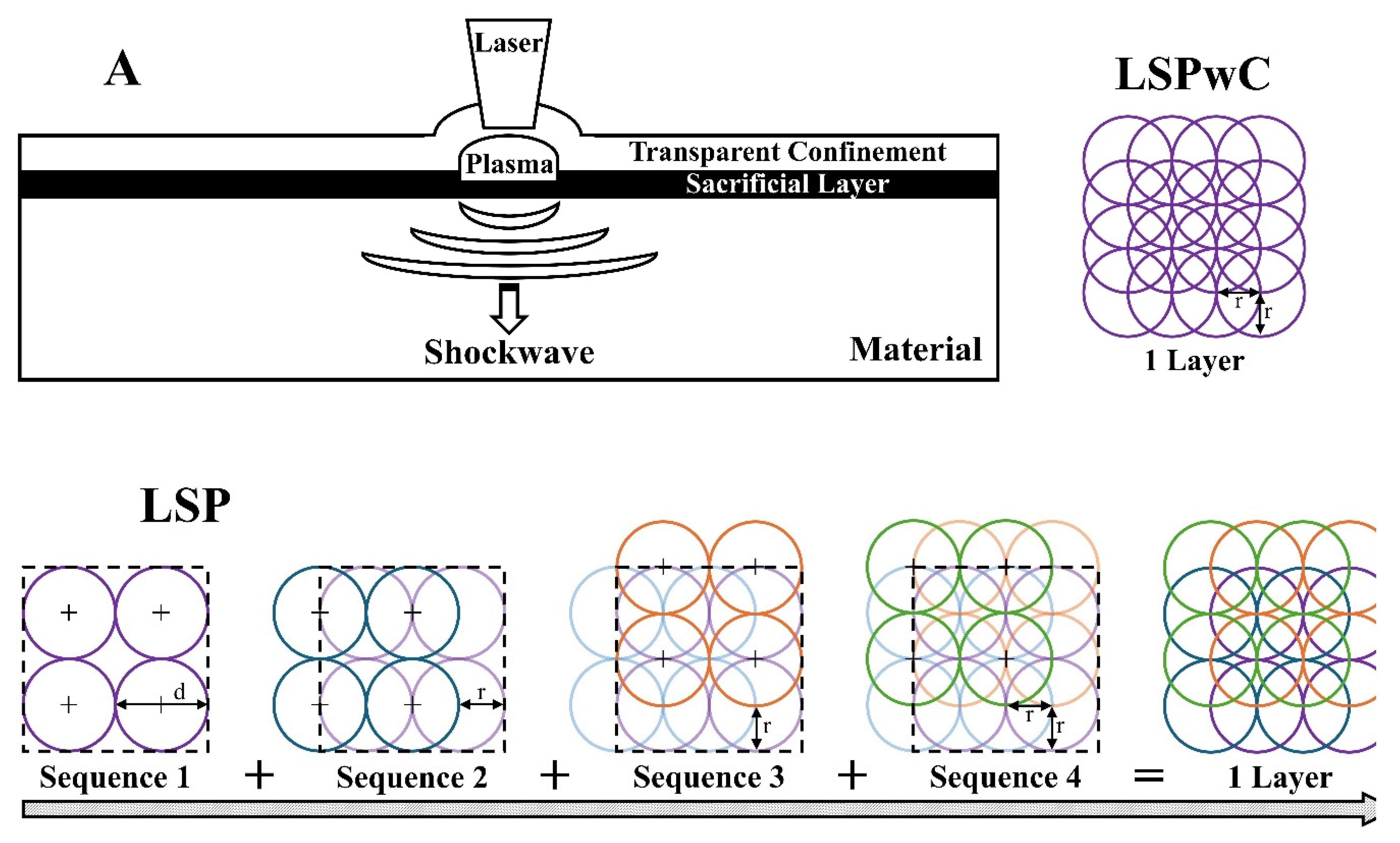
Figure 2.
SEM SE micrographs of as-polished 304L stainless steel in three conditions: (BL) baseline, (SEN1) sensitized for 5hrs, and (SEN2) sensitized for 24hrs. Precipitation of chromium-rich carbides is observed along grain boundaries in SEN1 and SEN2.
Figure 2.
SEM SE micrographs of as-polished 304L stainless steel in three conditions: (BL) baseline, (SEN1) sensitized for 5hrs, and (SEN2) sensitized for 24hrs. Precipitation of chromium-rich carbides is observed along grain boundaries in SEN1 and SEN2.
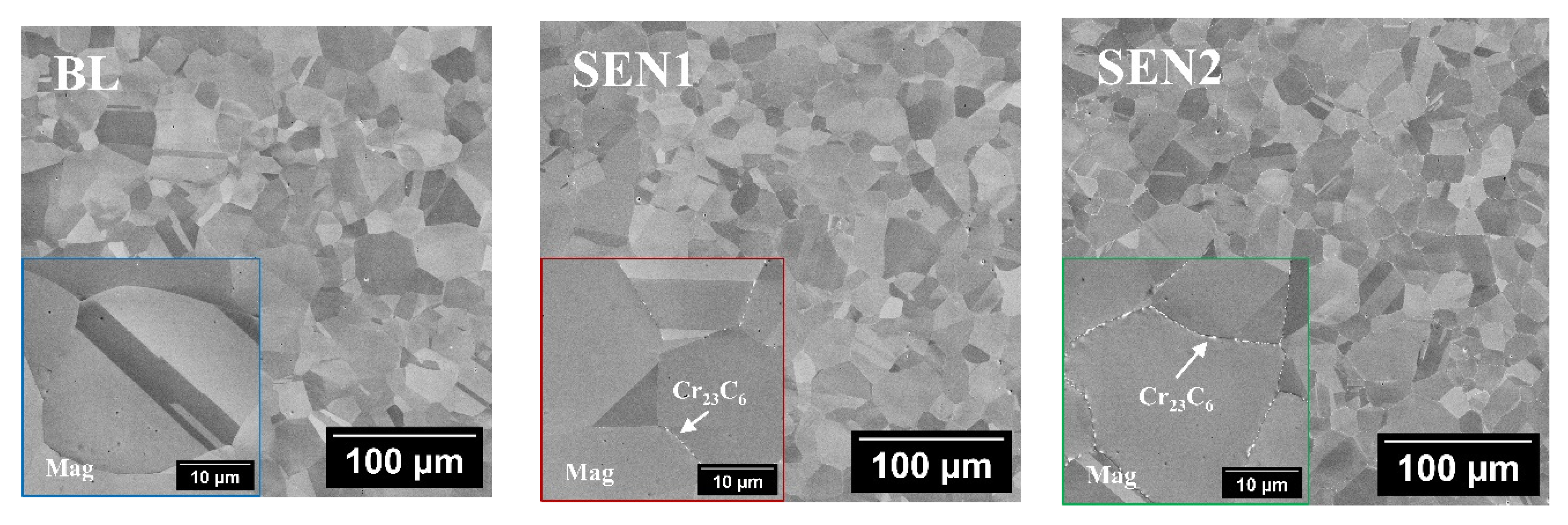
Figure 3.
(A) XRD patterns of as-polished BL, SEN1, and SEN2 specimens showing the presence of austenitic and martensitic phases. (B) XRD comparison of the BL specimen before and after electropolishing (EP), confirming that the martensitic phase was introduced during surface polishing.
Figure 3.
(A) XRD patterns of as-polished BL, SEN1, and SEN2 specimens showing the presence of austenitic and martensitic phases. (B) XRD comparison of the BL specimen before and after electropolishing (EP), confirming that the martensitic phase was introduced during surface polishing.
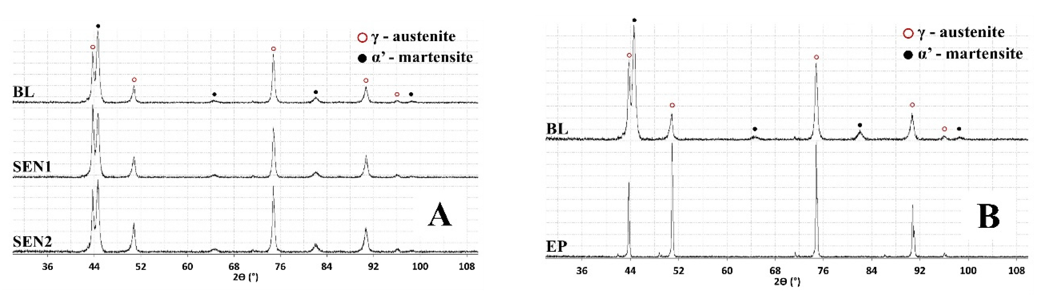
Figure 4.
XRD patterns of as-polished BL following laser shock peening (LSP) and laser shock peening without coating (LSPwC). Iron oxide peaks were observed in the LSPwC-treated specimen.
Figure 4.
XRD patterns of as-polished BL following laser shock peening (LSP) and laser shock peening without coating (LSPwC). Iron oxide peaks were observed in the LSPwC-treated specimen.
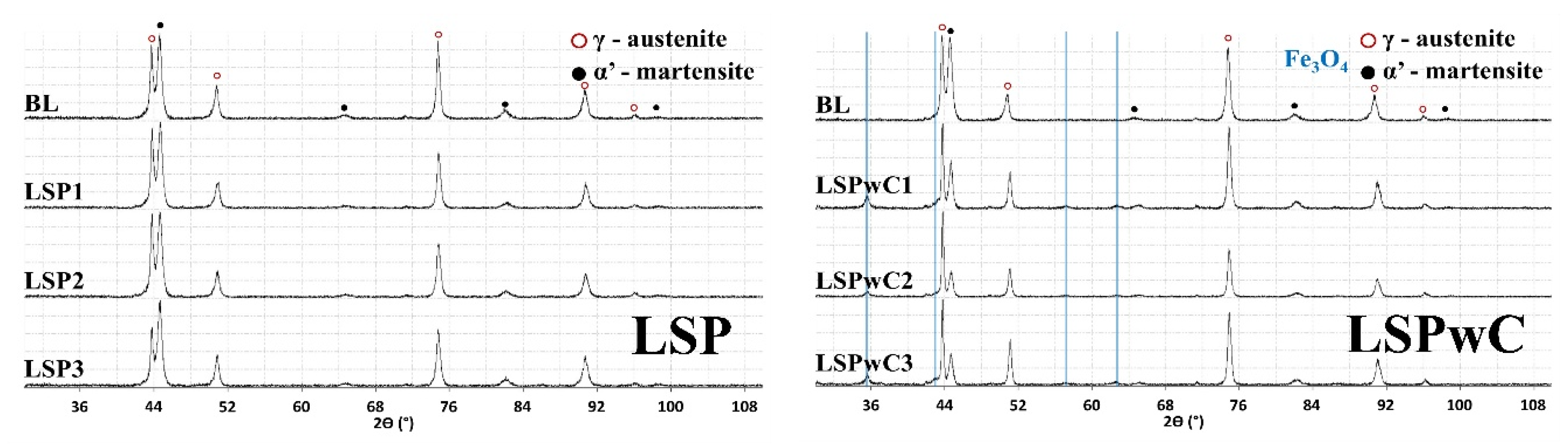
Figure 5.
3D surface profile with roughness average (Ra) and average max height (Rz) after LSP.
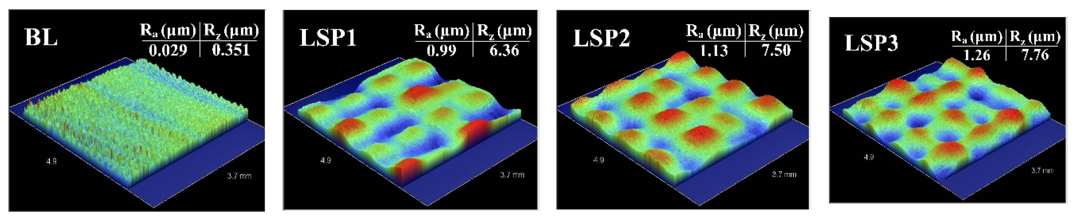
Figure 8.
Cyclic polarization curves for 304L stainless steel following sensitization heat treatment (0hrs, 5hrs, 24hrs), exposed to 0.5M H2SO4 + 0.05M KSCN.
Figure 8.
Cyclic polarization curves for 304L stainless steel following sensitization heat treatment (0hrs, 5hrs, 24hrs), exposed to 0.5M H2SO4 + 0.05M KSCN.
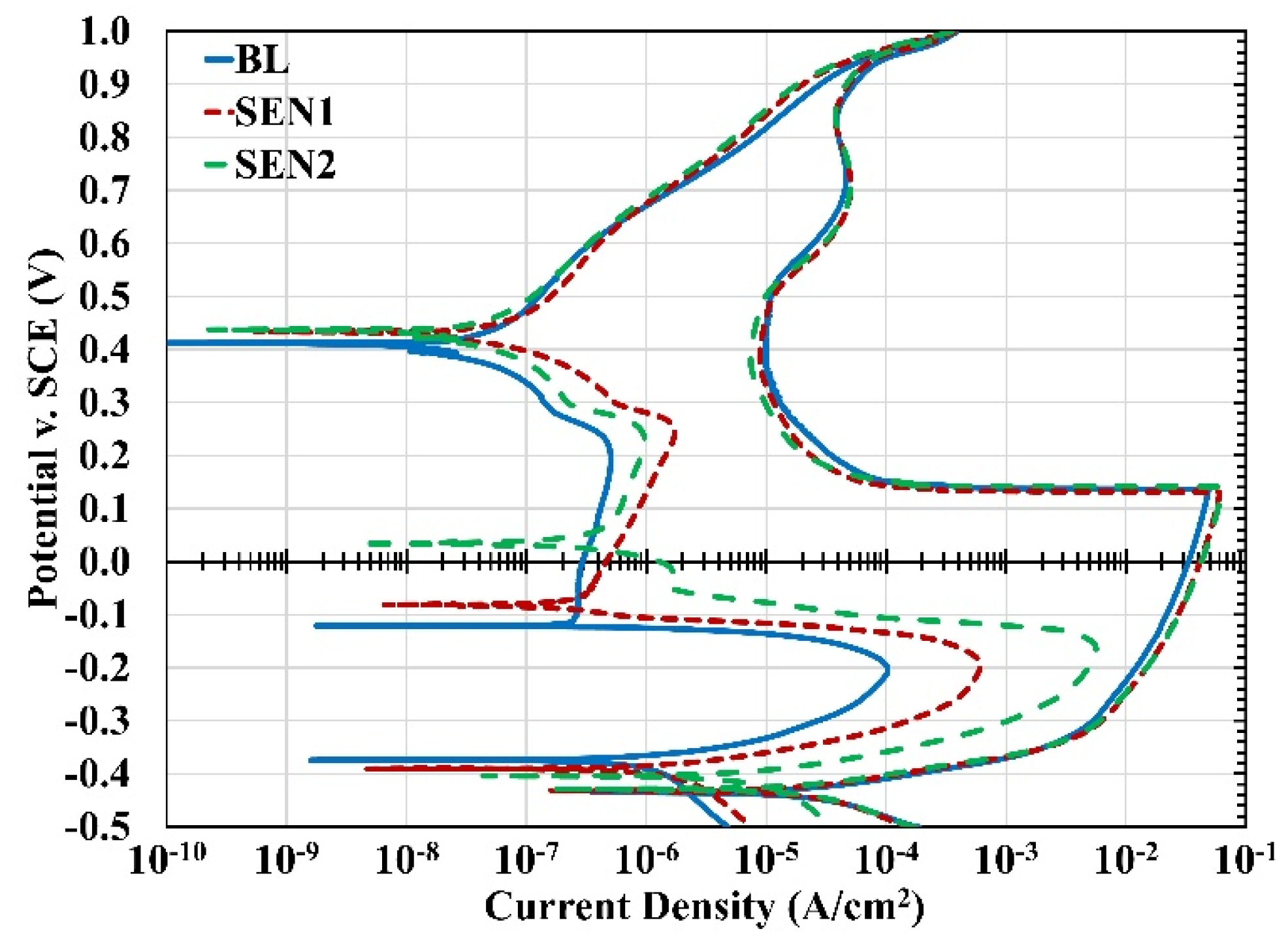

Table 1.
Weight percent composition of 304L stainless steel.
| Fe | Cr | Ni | Mn | Cu | Si | Mo | N | P | C | S | |
|---|---|---|---|---|---|---|---|---|---|---|---|
| 304L | Bal. | 18.19 | 8.05 | 1.30 | 0.36 | 0.34 | 0.27 | 0.070 | 0.028 | 0.025 | 0.001 |
Table 2.
Designation of specimens with parameters.
| Designation | Description |
|---|---|
| BL | As-Polished Baseline (600grit) |
| SEN1 | BL + 650 °C; 5hrs; Air Cooled (600grit) |
| SEN2 | BL + 650 °C; 24hr; Air Cooled (600grit) |
Table 3.
LSP Parameters.
| Specimen Condition | Spot size (mm) | Overlap (%) | Pulse Energy (J) | Power Density (GW/cm2) | Pulse Duration (ns) |
|---|---|---|---|---|---|
| LSP1 / LSPwC1 | 2 | 50 | 1 | 1.4 | 22.3 |
| LSP2 / LSPwC2 | 2 | 50 | 1.5 | 2.3 | 20.8 |
| LSP3 / LSPwC3 | 2 | 50 | 3 | 3.2 | 30.0 |
Table 4.
Proto LXRD residual stress measurement parameters for 304L stainless steel.
| Parameters | Description | |
|---|---|---|
| Material Phase | Austenite | Martensite |
| Detector | PSSD (Position Sensitive Scintillation Detector); 20° 2θ range | |
| Radiation Type | Mn Kα ( λ = 2.10 Å ) | Cr Kα ( λ = 2.29 Å ) / V Filter |
| Plane | {311} | {211} |
| Bragg’s Angle | 152.8° | 155.1° |
| Tilt Angles | 0.00°; ±2.61°; ±9.09°; ±12.40°; ±18.81°; ±23.00° | |
| Aperture Size | 2mm | |
| Exposure Time | 0.25s / 0.25s | 2.0s / 2.0s |
| X-Ray Elastic Constants | S1: -1.20 X 10⁻⁶ MPa-1 S2/2: 7.18 X 10⁻⁶ MPa-1 |
S1: -1.20 X 10⁻⁶ MPa-1 S2/2: 5.67 X 10⁻⁶ MPa-1 |
Table 5.
Percentage of deformation-induced martensite following LSP surface treatment.
| Specimen Condition |
BL | LSP1 | LSP2 | LSP3 | LSPwC1 | LSPwC2 | LSPwC3 |
|---|---|---|---|---|---|---|---|
| %Martensite | 9.42 | 10.06 | 10.77 | 11.64 | 9.07 | 9.08 | 8.18 |
Table 6.
Surface residual stress of as-polished BL specimens following LSP surface treatment.
| ID | Avg. Surface RS Aust. (MPa); 0° | Avg. Surface RS Aust. (MPa); 90° | Avg. Surface RS Mart. (MPa); 0° | Avg. Surface RS Mart. (MPa); 90° |
|---|---|---|---|---|
| BL | -165.2 ± 29.4 | -227.6 ± 25.6 | -561.3 ± 35.9 | -1281.0 ± 27.8 |
| LSP1 | -209.1 ± 34.3 | -266.8 ± 25.7 | -216.5 ± 37.2 | -886.9 ± 38.8 |
| LSP2 | -208.2 ± 30.2 | -249.2 ± 24.0 | -255.5 ± 35.9 | -780.5 ± 26.5 |
| LSP3 | -374.3 ± 24.1 | -397.6 ± 28.5 | -647. ± 32.99 | -935.0 ± 26.9 |
Table 7.
Electrochemical data from cyclic polarization curves for 304L stainless steel specimens (BL, SEN1, and SEN2) subjected to LSP and LSPwC, tested in 0.5M H2SO4 + 0.05M KSCN.
Table 7.
Electrochemical data from cyclic polarization curves for 304L stainless steel specimens (BL, SEN1, and SEN2) subjected to LSP and LSPwC, tested in 0.5M H2SO4 + 0.05M KSCN.
| Sample ID | ΔEcorr | ΔIcorr | %DOS | CR (mpy|mmpy) | |
| BL | +60.6 | −25.92e-6 | 0.21 | 28.24 | 0.718 |
| BL-LSP1 | +78.1 | −22.64e-6 | 0.04 | 27.25 | 0.622 |
| BL-LSP2 | +44.4 | −5.84e-6 | 0.87 | 8.55 | 0.195 |
| BL-LSP3 | +55.0 | −6.44e-6 | 0.39 | 9.53 | 0.218 |
| BL-LSPwC1 | −11.6 | −10.52e-6 | 1.21 | 17.24 | 0.394 |
| BL-LSPwC2 | −6.8 | −12.36e-6 | 1.05 | 19.41 | 0.444 |
| BL-LSPwC3 | −11.1 | −8.90e-6 | 1.10 | 15.20 | 0.348 |
| SEN1 | +41.1 | −21.52e-6 | 1.01 | 24.54 | 0.624 |
| SEN1-LSP1 | +56.6 | −7.21e-6 | 0.61 | 10.84 | 0.248 |
| SEN1-LSP2 | +43.1 | −7.99e-6 | 0.82 | 11.64 | 0.266 |
| SEN1-LSP3 | +56.9 | −12.46e-6 | 0.61 | 16.73 | 0.382 |
| SEN1-LSPwC1 | −6.1 | −6.56e-6 | 3.66 | 15.59 | 0.356 |
| SEN1-LSPwC2 | −8.8 | −8.77e-6 | 2.38 | 17.34 | 0.396 |
| SEN1-LSPwC3 | −3.7 | −3.67e-6 | 5.03 | 14.74 | 0.336 |
| SEN2 | +24.8 | −10.43e-6 | 8.86 | 23.51 | 0.597 |
| SEN2-LSP1 | +24.7 | +4.82e-6 | 11.99 | 20.50 | 0.469 |
| SEN2-LSP2 | +19.6 | +7.35e-6 | 9.66 | 11.54 | 0.264 |
| SEN2-LSP3 | +19.2 | +8.08e-6 | 11.32 | 10.27 | 0.235 |
| SEN2-LSPwC1 | −12.0 | −2.35e-6 | 11.01 | 17.16 | 0.393 |
| SEN2-LSPwC2 | −2.2 | +2.62-6 | 18.06 | 20.30 | 0.464 |
| SEN2-LSPwC3 | −7.2 | +3.06e-6 | 19.82 | 16.08 | 0.368 |
Disclaimer/Publisher’s Note: The statements, opinions and data contained in all publications are solely those of the individual author(s) and contributor(s) and not of MDPI and/or the editor(s). MDPI and/or the editor(s) disclaim responsibility for any injury to people or property resulting from any ideas, methods, instructions or products referred to in the content. |
© 2025 by the authors. Licensee MDPI, Basel, Switzerland. This article is an open access article distributed under the terms and conditions of the Creative Commons Attribution (CC BY) license (http://creativecommons.org/licenses/by/4.0/).
Copyright: This open access article is published under a Creative Commons CC BY 4.0 license, which permit the free download, distribution, and reuse, provided that the author and preprint are cited in any reuse.


