1. Introduction
Transparent conductive materials (TCMs) underpin a broad range of optoelectronic and thermal management devices, including smart windows, defogging/anti icing coatings, touch panels, and photovoltaics [
1,
2,
3,
4]. Indium tin oxide (ITO) remains the industrial go to because it combines high optical transmittance with low sheet resistance [
1,
4]. Yet ITO is intrinsically brittle and typically requires high-temperature vacuum deposition and post-annealing [
5,
6], which significantly limits its use on flexible substrates and raising costs due to indium scarcity [
1].
Other commonly used materials, silver nanowire (AgNW) networks, deliver excellent conductivity at high transmittance and can be solution processed, making them compatible with roll-to-roll coating and other processes [
4,
7,
8]. However, long-term reliability is undermined by thermally accelerated oxidation during Joule heating, thermal instability, cracking, and junction corrosion, all of which increase resistance [
9,
10,
11]. Carbon-based TCMs, particularly carbon nanotube (CNT) networks, offer a compelling alternative: they are chemically stable in air, highly flexible, and compatible with scalable, low-temperature, solution processing [
4,
12,
13]. Additionally, MWCNTs are significantly more cost-effective than both SWCNTs and silver nanowires, with industrial-grade MWCNTs priced at
$50-150/kg compared to SWCNTs at
$1,000-5,000/kg [
14]. These attributes have already enabled CNT-based transparent heaters with rapid thermal response and robust cycling stability [
15,
16,
17].
At the material level, single-walled CNTs (SWCNTs) typically afford superior optical clarity at a given sheet resistance because of their small diameters and lower light scattering [
18,
19,
20]; however, SWCNTs are costly due to highly complex and controlled production requirements [
19,
21]. Multi-walled CNTs (MWCNTs), on the other hand, are far more cost-effective, approximately 10-15 times cheaper [
22] and readily available at scale, but the larger diameters and bundling generally raise percolation thresholds and haze, while interlayer scattering, mismatching chirality, inter-shell tunneling yield higher sheet resistance at a given density compared to metallic SWCNT networks [
15,
18,
23]. A promising route to narrow this gap is the use of ultra-long CNTs (ULCNTs) which are mix of single and multiwalled (length > 100 µm, potentially cm’s length): the increased tube length reduces junction density per unit area, thereby lowering junction-limited resistance in the percolating network [
18,
24,
25].
Despite these advances, ultra-long CNTs (ULCNT) transparent heaters remain comparatively underexplored relative to SWCNT systems, particularly in water-based, low-temperature processing schemes suitable for plastics [
15,
16,
23]. Addressing this gap is attractive because it couples material cost and supply chain advantages with manufacturing simplicity [
13,
19].
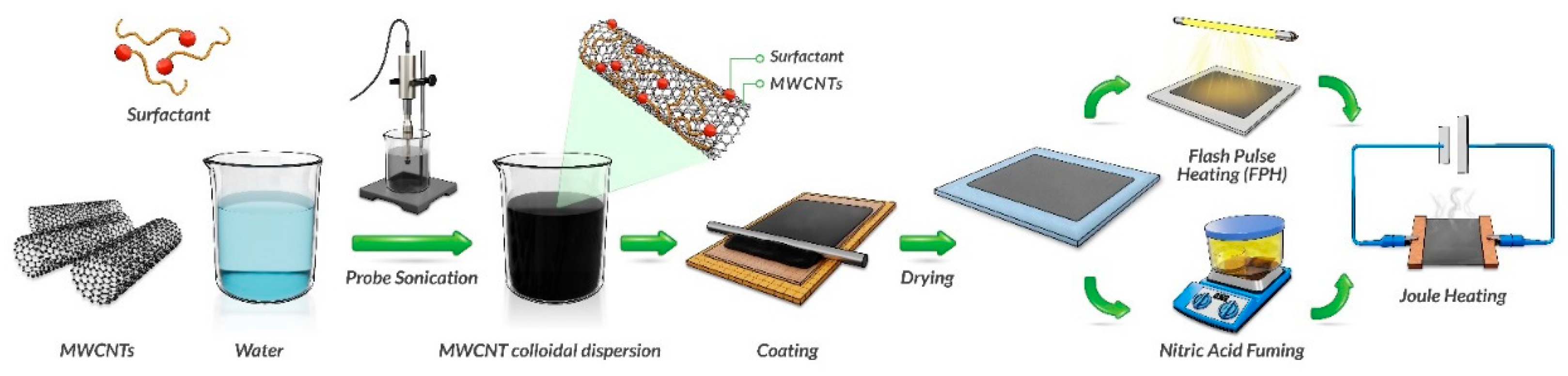
Figure 1 Shows the process which was developed to produce Transparent ULCNT-based heaters, making it an attractive material for large area coatings, where durability and scalability are required, along with optoelectronic performance [
12,
26,
27]. This work develops and studies aqueous ULCNT transparent heater coatings deposited by scalable, low-temperature rod coating onto glass and flexible polymer substrates (PET and PC). This work includes (i) design of surfactant-assisted dispersions of ULCNTs into water; (ii) relating layer count to the transmittance–sheet resistance (T–R
s) trade off, as well as heating performance while electrically biased; and (iii) evaluate two different post-deposition treatments—nitric acid fume doping and flash photonic heating to enhance optoelectrical performance further, as well as, analyze heater response under constant-voltage drive (rise time, steady-state temperature, and anisotropy performance with respect to draw direction), and durability.
2. Materials and Methods
Ultra-long carbon nanotubes (UL-CNTs, TorTech CNTM1.5) were used as the conductive component. Aqueous dispersions were prepared in two approaches: The first by evaluating different surfactants, including, 0.6wt% of Triton X-100, polyacrylic acid sodium salt, Tween 80, sodium dodecyl sulfate (SDS), and Solsperse 46000 which was examined in three concentrations 0.3wt%, 0.6 wt%, and 1.2 wt%. The second is by functionalization the CNT surface by refluxing in 70% nitric-acid. Each formulation contained 0.2 wt% CNTs and 0.14 wt% BYK 348 in 100 ml triple-distilled water (TDW). The mixtures were probe-sonicated (VCX 750, 85% amplitude, 2.5 h) in an ice bath to prevent overheating.
2.2. Film Deposition
Glass, polycarbonate (PC), and polyethylene terephthalate (PET) substrates were first cleaned by ultrasonic bath for 5 min, then wiped thoroughly with isopropyl alcohol (IPA) and air-dried. Flow coating was performed by pipetting 0.5 ml of ink onto the substrate with a #3 kbar (24 µm wet thickness) to form films of 1–5 layers. Each layer was dried at 75 °C for 10 min before the next layer was applied. Layer count was used to tune sheet resistance (Rₛ) and optical transmittance (T₅₅₀).
2.3. Post-Treatments
Nitric Acid Fuming: Films were exposed to 70% HNO₃ vapor at 65 °C for 0.5–36 min under an inverted glass dome, then rinsed with isopropanol (IPA) and air-dried. Flash Photonic Heating (FPH): FPH was performed using a NovaCentrix PulseForge xenon-lamp system (0.1–1 J/cm², 1–5 pulses, 500 µs each). The process was conducted in ambient air.
2.4. Characterization
Optical transmittance spectra were recorded using a UV–Vis spectrophotometer. Sheet resistance was measured by four-point probe. Heating characteristics were studied using a programmable DC power supply and a Qianli Toolplus thermal IR camera. Mechanical durability was tested under 5000 bending cycles with the Ufactory Arm Lite 6 with the Lite gripper attached. Surface chemistry before and after FPH was analyzed via X-ray photoelectron spectroscopy (XPS, Thermo K-Alpha, Al Kα source), focusing on C1s and O1s peaks.
3. Results
3.1. Ink Dispersion and Stability
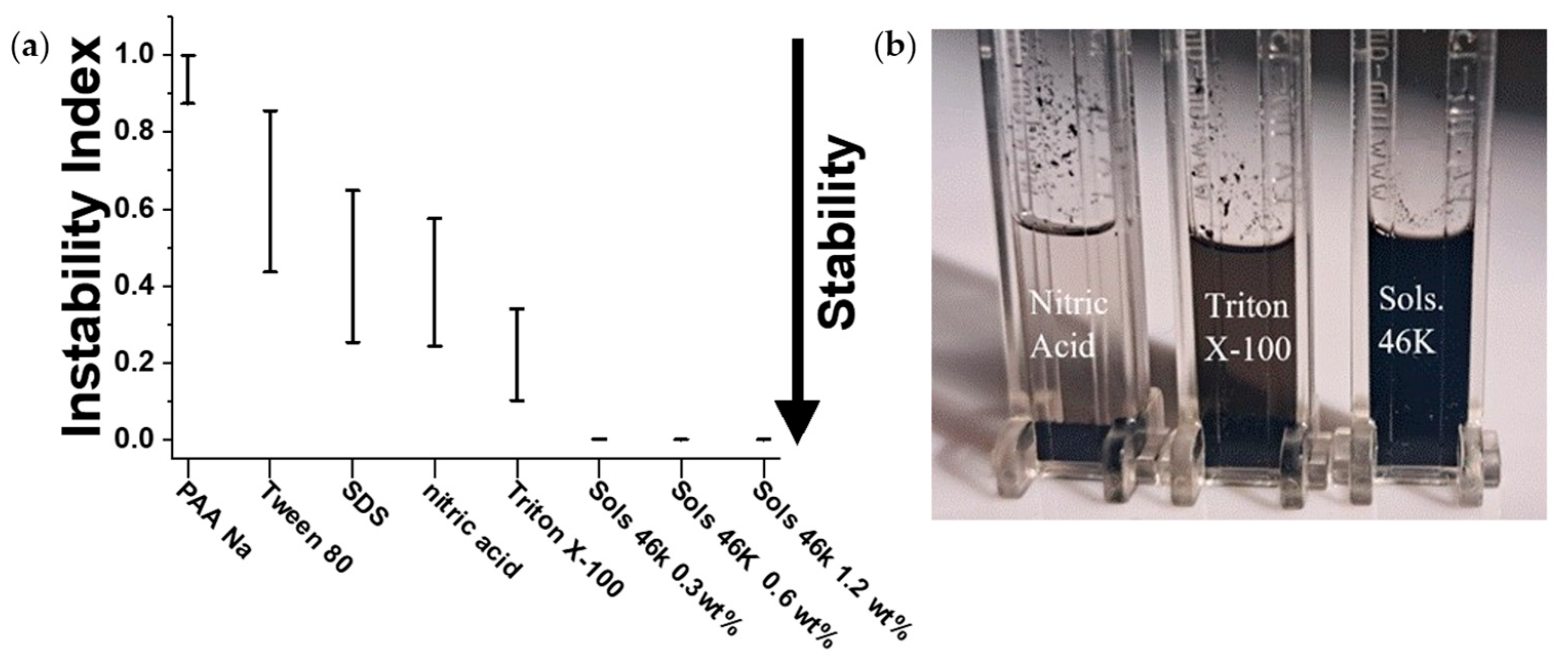
The ink formulation was prepared by dispersing of mixed single and multi-walled ultra-long carbon nanotubes (UL-CNTs) in water using surfactants to promote colloidal stability and uniform film formation. Achieving stable dispersion is critical for ensuring long shelf life, consistent coating performance, and reproducibility of the optoelectronic properties. Instability, such as CNT sedimentation or aggregation, leads to non-uniform film thickness, poor transparency, and reduced conductivity [
28,
29]. To identify the optimal dispersant system, several surfactants were investigated. The stability of each aqueous ink was evaluated using accelerated sedimentation analysis (Lumifuge), which quantifies the rate and extent of phase separation under centrifugal force (4000 rpm, 25 °C). As shown in
Figure 2a, the instability index for the Solsperse 46000 systems reaches a near-zero instability index. The difference in performance of the different surfactant can be futher demonstrated in
Figure 2b as the different there is clear visual difference between the nitric acid (Instability Index ~0.42), Triton X-100 (Instability Index ~0.25), and Solsperse 46K 1X (Instability Index ~0.01) appears darker and less transparent as the instability decreases. Although the measurement of 0.3wt% concentration looks similar to that of 0.6wt% and 1.2wt%, it failed to disperse the whole amount of CNTs and many big particles were observed on the walls of the measurement tube. Therefore, we proceeded with the 0.6wt% concentration because higher surfactant content 1.2wt% would introduce excess organic material, potentially reducing film conductivity by blocking charge transport pathways between CNTs [
30,
31,
32]. This balance between dispersion stability and final electrical performance made the 0.6wt% Solsperse formulation the optimal choice. All other surfactants, and nitric-acid-functionalized CNTs, exhibited much higher instability indexes (>0.3), reflecting sedimentation or phase separation during centrifugation. 0.6wt% Solsperse 46000 thus provided a uniform, durable dispersion with minimal aggregation due to its polymeric structure, which provides both
anchoring and
stabilizing functionality in water. The molecule contains multiple polar anchoring groups capable of π–π and donor–acceptor interactions with the graphitic sidewalls of carbon nanotubes, ensuring strong, multi-point adsorption [
33,
34]. Its long-solvated polymer chains then extend into the aqueous phase, forming a thick electrostatic barrier that prevents tube–tube re-aggregation. In contrast, the smaller ionic or nonionic surfactants (SDS, Triton X-100, Tween 80) rely on weak, reversible physisorption and produce only a thin, labile stabilizing layer, while the polyelectrolyte PAA-Na provides purely electrostatic stabilization that is easily screened in water [
29,
35]. The combined
electrostatic and
steric mechanism of Solsperse 46000 therefore yields a more durable, ionic-strength-independent dispersion and preserves the ultra-long CNT aspect ratio essential for low percolation resistance and uniform transparent films.
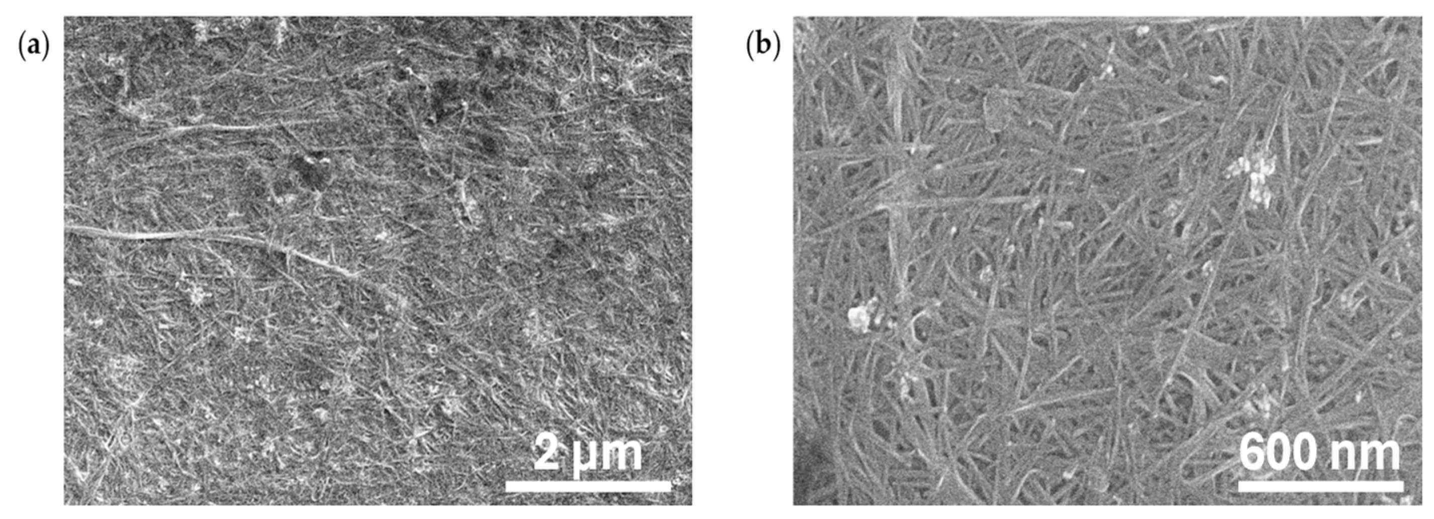
Figure 3a,b show scanning electron microscopy (SEM) image confirming a continuous CNT network with minimal bundling when using Solsperse 46000. The images show extended nanotube paths forming dense, conductive webs. The long tube length and uniform dispersion minimize contact resistance by reducing the number of junctions [
18,
24]. This morphology resembles optimized CNT networks reported for transparent electrodes [
12,
19,
20,
36].
3.2. Optical and Electrical Properties of CNT Films
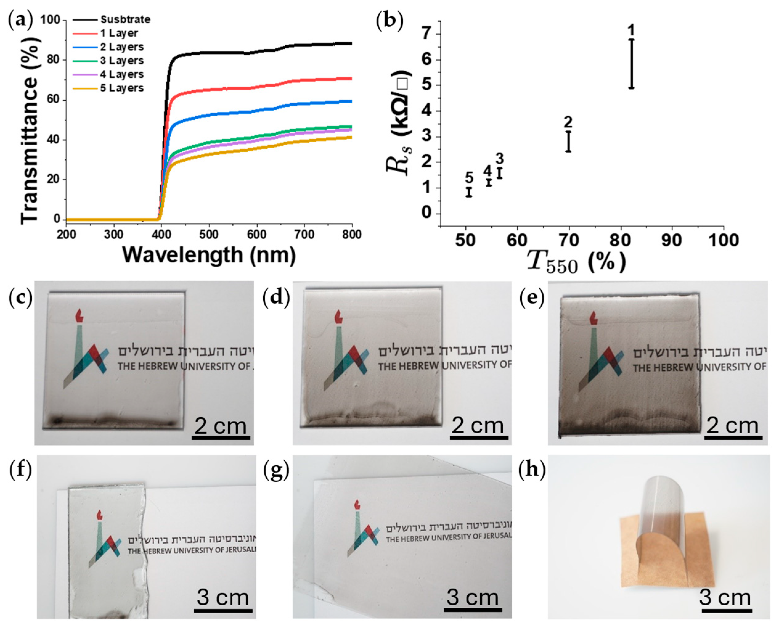
Figure 4a shows the full UV-Vis spectra indicating a trend of reduced % transmittance with the addition of more layers, i.e., more material. Beyond the abrupt cut-off below ~400 nm (intrinsic to the PC substrate and therefore of little relevance to transparency of the ULCNTs coating). We subtracted the transmittance of the substrate T% PC from the transmittance of the coated samples to account for the substrate’s effect.
Figure 4b reveals a compromise between high optical transparency and low sheet resistance that emerges when layers are added successively. Each pass of the #3 Mayer-Rod (~24 µm wet thickness) adds CNT to the percolating network, resulting in less optical transparency and lower sheet resistance (Rₛ). The reduction in transparency and sheet resistance increases with each additional layer (
Figure 4c-e). From one-layer to two-layer, the sheet resistance and optical transparency (at 550 nm) decreased by ~60% and ~14%, respectively. Although a two-layer film already offers a reasonable compromise (~2.3kΩ/□ at ~70% T
550), we continued to explore the transparency limit. We therefore focused subsequent optimization on the single-layer film, accepting its higher Rₛ in exchange for ~85% visible transmission.
Taken together,
Figure 4a,b demonstrate that flow coating provides a straightforward yet tunable route to transparent conductive films whose optoelectronic properties can be adjusted by layer count. A single-layer coating delivers the highest clarity while still establishing electrical continuity. In contrast, five layers achieve the lowest Rₛ but at the cost of significant darkening, illustrating the practical limits of this material system for applications that demand both high transparency and low sheet resistance. Beyond tunability the ink also exhibits excellent versatility and substrate compatibility, yielding uniform coatings on glass (
Figure 4f) and PET (
Figure 4g-h) without noticeable defects. The ability to form adherent, continuous CNT networks on both rigid and flexible substrates underscores the robustness of the surfactant-assisted dispersion and the suitability of this method for scalable fabrication of transparent conductive films.
3.3. Electrical Heating Performance
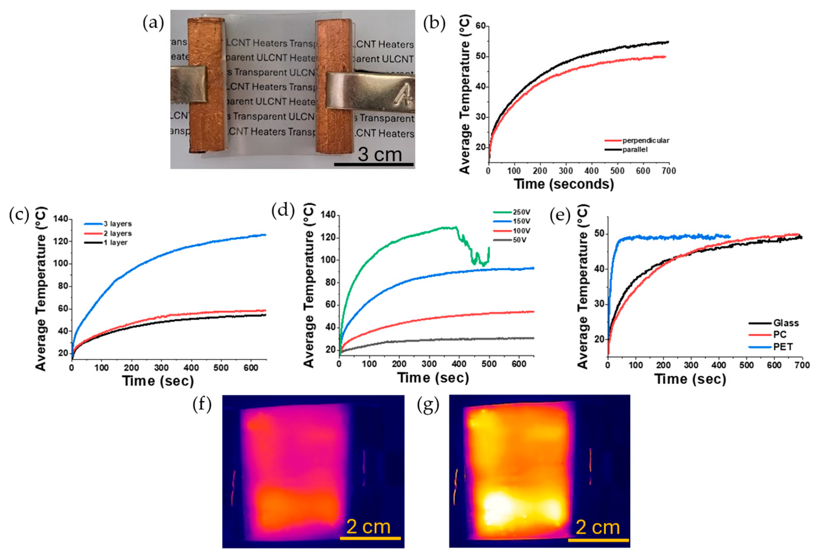
Figure 5b investigates the effect of flow-coating direction. When the electrodes are placed parallel to the coating direction, the applied current is perpendicular to it, coinciding with the preferential orientation of the percolating carbon network [
37,
38]. The single-layer film rises from 45 °C after 700s at 100 V to 53 °C when the electrodes are switched from perpendicular to parallel, resulting in roughly an 8 °C increase in temperature. This directional heating behavior reflects the anisotropic conductivity characteristic of shear-aligned CNT networks, in which enhanced conductivity perpendicular to the electrode alignment direction results in greater Joule heating [
37,
38,
39] and therefore motivates the use of the parallel-electrode geometry in all subsequent tests.
With that geometry fixed,
Figure 5c overlays heating curves for 1-, 2-, 3-layer coatings, each at 100 V. Because electrical power scales as V²/R lowering the sheet resistance by adding layers accelerates the temperature rise: the three-layer film (Rₛ ≈ 1.5 kΩ/□) surpasses 100 °C within 400 s, whereas the single layer (Rₛ ≈ 9.5 kΩ/□) levels off near 53 °C. The 4 and 5-layer samples initially heated rapidly, but then burned, melted, and disrupted the uniformity of the coatings, leading to a break in the percolation network and ceasing the joule heating.
Figure 5d isolates a single-layer heater while sweeping the bias from 50 V to 250 V. The response is monotonic, with the resulting plateau temperature being ≈ approximately 30 °C at 50 V, 55 °C at 100 V, 90 °C at 150 V, and exceeding 120 °C at 250 V, beyond which the substrate is damaged (melted and burned), resulting in the breaking of the coating. The infrared images in
Figure 5f,g show that the CNT film heats evenly across the entire active area at both voltages, confirming uniform electrical and thermal conductivity. As expected, the sample driven at 150 V reaches a higher overall temperature than the one at 100 V, while maintaining the same homogeneous heating profile.
Substrate effects are illustrated in
Figure 5e, where one-layer heaters deposited on glass, PC and PET were all driven at 100 V. While glass has the lowest specific heat of 0.85 (J/g·K) [
40,
41] compared to PC (1.2 J/g·K) [
42] and PET (1.3 J/g·K) [
43,
44,
45], the PET sample had significantly less mass compared to the other samples making it heat the fastest among the sample, reaching 50 °C in under 30 ss. In contrast, the glass and PC samples have taken 500+ seconds to achieve the same temperature. All three eventually plateau to the same final temperature, while the rate of the heater is dependent on the material and mass of the substrate, the final temperature achieved at a given voltage isn’t affected by the material.
Taken together, the data in
Figure 5 demonstrate that a single, optically clear CNT layer can deliver ~45 °C within one minute at 100V, readily available for low-voltage electronics. In comparison, the addition of layers or higher bias extends the operating range well above 100 °C. Crucially, every configuration settles to a stable plateau, providing predictable self-limiting behavior desirable for transparent defoggers, flexible warmers, and related large-area devices.
3.4. Flexibility and Durability
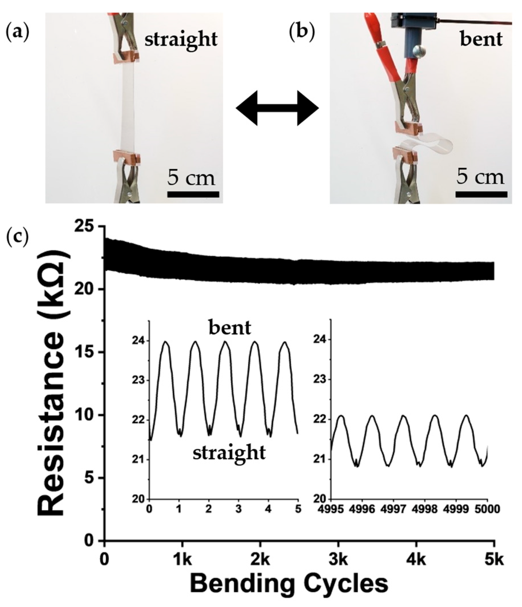
Figure 6 presents the durability of the 1-layer PET sample by repeatedly bending the sample, for 5000 cycles, using an automated xArm-6 robotic platform. The sample has a length of 13 cm, and was bent to bring one end straight down to the other, stopping with 3 cm in between, with the whole cycle lasting 7 seconds. Remarkably, the resistance of the bent sample decreased from 24 kΩ at the beginning of bending to 22 kΩ after extended cycling, while the unbent resistance started at 21.5 kΩ and ended at 21 kΩ. This gradual reduction in resistance demonstrates an improvement in ULCNT heaters and no observable degradation caused by bending. The improved conductivity is a phenomenon consistent with CNT networks, which exhibit stable or enhanced conductivity under mechanical deformation due to possible microstructural rearrangement. After 5000 cycles, the samples showed no changes in optical appearance or heating performance during operation at 100 V, corroborating the high mechanical durability while maintaining its optoelectronic properties. Such stability far exceeds that of brittle ITO or oxidation-prone AgNW-based heaters [
6,
10]. Additionally, the reproducible change in resistance between straight (
Figure 6a) and bended (
Figure 6b) states demonstrates a promising potential as a bending sensor, with application for real-time monitoring in smart surfaces [
46,
47].
3.5. Post-Treatment Effects
3.5.1. Nitric Acid Fuming
To further improve the conductivity of the films, two approaches were evaluated: the first is to expose the samples to nitric acid vapor, and the second is to treat the samples with flash photonic heating (FPH). Nitric acid vapor treatment is a well-established chemical doping method for enhancing CNT film conductivity by inducing p-type doping through charge transfer and removing insulating surfactant residues [
48,
49].
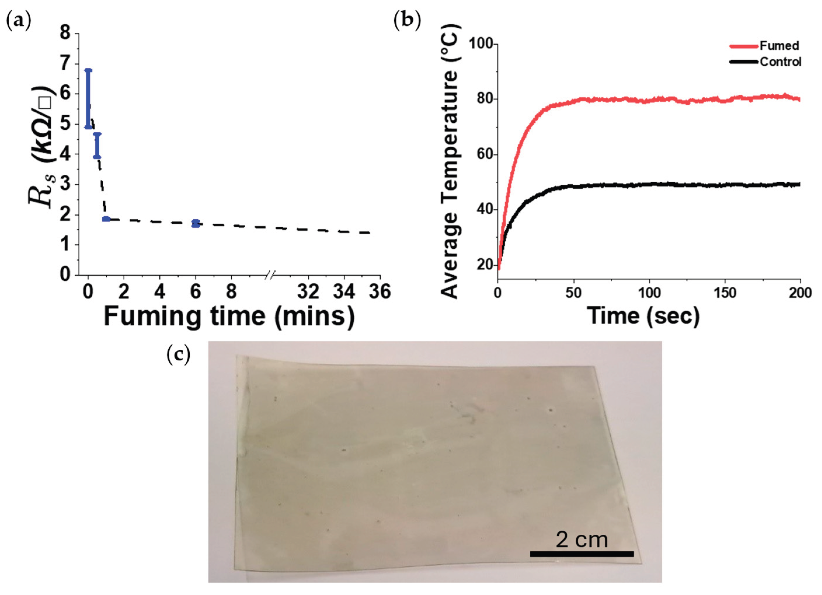
The nitric acid vapors resulted in a rapid decrease in sheet resistance of single layer ULCNT films on PET (
Figure 7a). Most of the improvement occurred within the first minute: Rₛ fell from ~7.5 kΩ/□ to ~2 kΩ/□¹ after 1 min, while longer fuming (≥ 30 min) delivered only modest additional reduction (approaching ~1.75 kΩ/□). Thus, the effective window for conductivity enhancement is in the short-exposure regime.
The electrical gains translated into higher heater output (
Figure 7b). A 1-minute fumed film plateaued at ~60 °C under 100V, whereas the undoped control plateaued near ~45 °C, with similar rise-time profiles.
Figure 8c shows a non-coated PET substrate after 6 min of fuming, which results in visible yellowing and substrate wrapping. Discoloration intensified with longer exposures, indicating a trade-off between maximum potential conductivity and optical clarity when using polymer substrates. Short fuming times (1 min) deliver the majority of the improvement while minimizing the yellowing, although minor yellow and substrate wrapping do occur; extended fuming yields diminishing electrical returns alongside progressively worse appearance. These constraints motivated the evaluation of a non-chemical post-treatment (FPH) in the following subsection.
3.5.2. Flash Photonic Heating
Flash photonic heating (FPH), also known as intense pulsed light or photonic sintering, is a rapid, non-contact post-treatment method that delivers high-intensity broadband light pulses to materials. Unlike thermal annealing [
50], FPH selectively heats the absorbing CNT network through photothermal conversion while minimizing substrate heating, making it compatible with heat-sensitive polymers. The rapid heating and cooling cycles can remove volatile impurities, improve inter-tube contacts, and potentially reduce oxygen-containing functional groups at CNT surfaces, thereby enhancing electrical conductivity [
51,
52,
53].
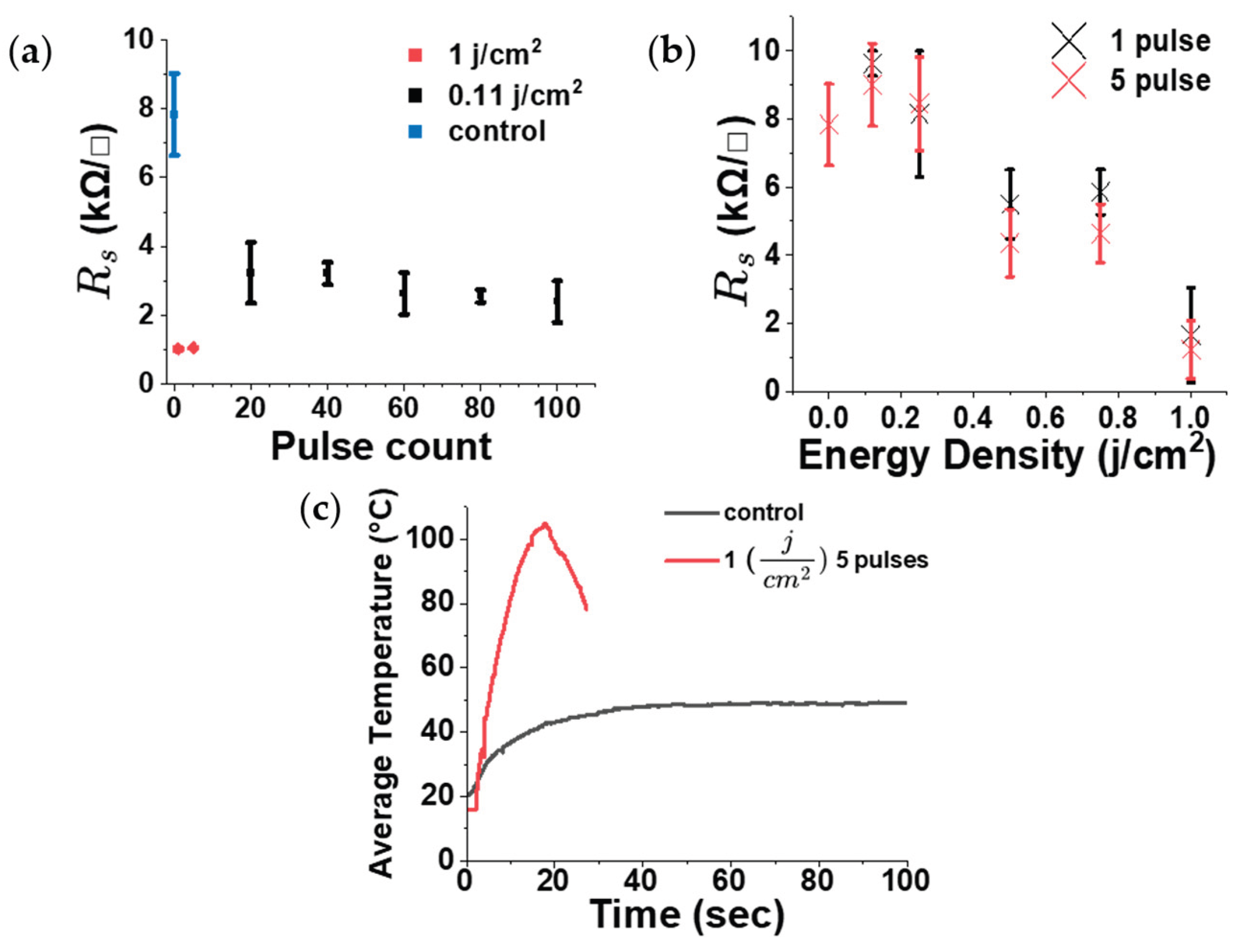
Figure 8 compares how sheet resistance changes with pulse count for two approaches: many low-energy pulses versus fewer high-energy pulses. At low pulse energy (0.11 J/cm²), increasing the number of pulses from 20 to 100 resulted in only minor reductions in sheet resistance, with most of the improvement occurring within the first 20 pulses. Conversely, even a few (1 or 5) high-energy pulses at 1 J cm⁻² reduced the sheet resistance more effectively than all of the low-energy (0.11 J cm⁻²) pulsed samples, underscoring the dominant role of pulse energy. This is further explored in sheet resistance vs. energy density (fixed pulse counts) (
Figure 8b), from 0 (control) to 1 J/cm², with 1-pulse and 5-pulse treatments showing a clear pattern of decreasing Rₛ with increasing energy density. Notably, 1-pulse and 5-pulse traces nearly overlap at each energy, demonstrating that per-pulse energy is the dominant factor in improving conductivity rather than pulse repetition. The 5-pulse samples provide only a slight additional reduction in sheet resistance compared to the 1-pulse samples, but the much smaller error bars indicate improved uniformity and reliability. Therefore, due to the improved consistency at 5 pulses, we selected 5 pulse for all subsequent experiments. Under optimized conditions (1 J cm⁻², 5 pulses), the sheet resistance of single-layer films decreased to ~1.2 kΩ/□, comparable to nitric-acid fuming of 2 kΩ/□ achieved after 36 min.
The electrical improvement translated to significantly higher heater output, under 100 V on PET, FPH-treated film (1 J cm⁻², 5 pulses) reached >100 °C within 20 seconds before the film started to burn and destroy the sample. In contrast, the untreated control stabilized near ~45 °C (
Figure 8c).
Across 0–1 J cm⁻², no measurable yellowing or visible damage was observed on PET substrates, and no measurable change in transmittance occurred. SEM imaging revealed no noticeable junction welding or large-scale reorganization of the CNT network after FPH, suggesting that the conductivity gains arise from subtle inter-tube/contact changes or chemical change of the film rather than macroscopic restructuring.
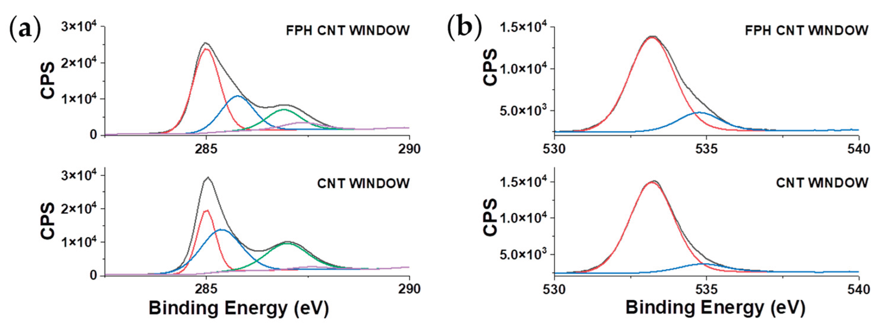
The XPS C 1s spectra of the untreated and FPH-treated MWCNT samples demonstrate substantial chemical changes on the nanotube surface following FPH processing (
Table 1). The untreated sample exhibited a high proportion of oxygenated carbon species, with the C–O and C=O components accounting for approximately 42% and 27% of the total signal, respectively. These groups originate primarily from surfactant residues and moderate CNT surface oxidation that occurred during dispersion.
After FPH treatment, a significant reduction in the oxygen-containing functional groups was observed. The relative proportions of C–O and C=O bonds decreased to 26% and 16%, respectively. Concurrently, the hydrocarbon (C–H) component increased from 29% in the untreated sample to 52% after treatment. This sharp rise indicates that the treatment effectively removed oxygen-rich surfactant layers and partially restored graphitic carbon domains on the CNT surface [
54,
55].
Interestingly, the COOH fraction increased slightly from 1.9% to 6.2%, suggesting that the treatment either generated defect-associated carboxyl groups at CNT ends or exposed preexisting carboxylic sites by stripping away overlying residues [
56,
57]. Overall, the FPH process acted as a chemical cleaning and mild reduction step, yielding a less oxidized, more conductive, and structurally restored CNT surface. This trend aligns with previous reports describing similar reductions in polar oxygen groups and reestablishment of sp² carbon bonding after plasma or hydrogen-based CNT treatments [
58,
59].
Figure 9.
XPS of CNT films before and after FPH: (a) C 1s deconvolution showing increased sp² fraction; (b) O 1s showing reduced oxygen functionalities.
Figure 9.
XPS of CNT films before and after FPH: (a) C 1s deconvolution showing increased sp² fraction; (b) O 1s showing reduced oxygen functionalities.
4. Conclusion
Ultralong CNTs aqueous dispersions deposited onto various substrates by scalable flow-coating process, enable fabrication of a transparent heaters with tunable T–Rₛ trade-offs with fast, uniform Joule heating. The single-layer coating achieves good sheet resistances at ≥80% transmittance. Post-processing provides two complementary routes: short HNO₃ fuming yields immediate conductivity gains but warps and yellows polymeric substrates, whereas flash-pulse heating enhances performance without liquid chemicals and avoids yellowing. The transparent heaters maintained electrical conductivity under repeated bending, underscoring suitability for flexible defogging/deicing and wearable devices. Overall, the combination of aqueous formulation, scalability of process, and a simple post-treatment to further enhance performance, offers a low-cost, manufacturing-ready pathway to high-clarity CNT heaters. The heaters can be used for a variety of fields, including bending /stretching sensors and transparent thermal actuators, for applications in electronics, optoelectronics and robotic devices.
Acknowledgments
This work was supported partially by the Israel Ministry of Defense and by the National Research Foundation, Prime Minister’s Office, Singapore, under its Campus of Research Excellence and Technological Enterprise (CREATE) program. We thank Tortech for providing the ULCNTs.
References
- Ellmer, K. Past Achievements and Future Challenges in the Development of Optically Transparent Electrodes. Nat Photonics 2012, 6, 809–817. [Google Scholar] [CrossRef]
- Granqvist, C.G. Transparent Conductors as Solar Energy Materials: A Panoramic Review. Solar Energy Materials and Solar Cells 2007, 91, 1529–1598. [Google Scholar] [CrossRef]
- Fortunato, E.; Ginley, D.; Hosono, H.; Paine, D.C. Transparent Conducting Oxides for Photovoltaics. MRS Bull 2007, 32, 242–247. [Google Scholar] [CrossRef]
- Hecht, D.S.; Hu, L.; Irvin, G. Emerging Transparent Electrodes Based on Thin Films of Carbon Nanotubes, Graphene, and Metallic Nanostructures. Advanced Materials 2011, 23, 1482–1513. [Google Scholar] [CrossRef]
- Chen, Z.; Cotterell, B.; Wang, W.; Guenther, E.; Chua, S.-J. A Mechanical Assessment of Flexible Optoelectronic Devices.
- Park, J.M.; Wang, Z.J.; Kwon, D.J.; Gu, G.Y.; Lawrence Devries, K. Electrical Properties of Transparent CNT and ITO Coatings on PET Substrate Including Nano-Structural Aspects. Solid State Electron 2013, 79, 147–151. [Google Scholar] [CrossRef]
- Lee, J.Y.; Connor, S.T.; Cui, Y.; Peumans, P. Solution-Processed Metal Nanowire Mesh Transparent Electrodes. Nano Lett 2008, 8, 689–692. [Google Scholar] [CrossRef] [PubMed]
- Tokuno, T.; Nogi, M.; Karakawa, M.; Jiu, J.; Nge, T.T.; Aso, Y.; Suganuma, K. Fabrication of Silver Nanowire Transparent Electrodes at Room Temperature. Nano Res 2011, 4, 1215–1222. [Google Scholar] [CrossRef]
- Khaligh, H.H.; Xu, L.; Khosropour, A.; Madeira, A.; Romano, M.; Pradére, C.; Tréguer-Delapierre, M.; Servant, L.; Pope, M.A.; Goldthorpe, I.A. The Joule Heating Problem in Silver Nanowire Transparent Electrodes. Nanotechnology 2017, 28, 425703. [Google Scholar] [CrossRef]
- Choo, D.C.; Kim, T.W. Degradation Mechanisms of Silver Nanowire Electrodes under Ultraviolet Irradiation and Heat Treatment. Sci Rep 2017, 7, 1–12. [Google Scholar] [CrossRef]
- Jeong, Y.C.; Nam, J.; Kim, J.; Kim, C.S.; Jo, S. Enhancing Thermal Oxidation Stability of Silver Nanowire Transparent Electrodes by Using a Cesium Carbonate-Incorporated Overcoating Layer. Materials 2019, 12, 1140. [Google Scholar] [CrossRef]
- Park, S.; Vosguerichian, M.; Bao, Z. A Review of Fabrication and Applications of Carbon Nanotube Film-Based Flexible Electronics. Nanoscale 2013, 5, 1727–1752. [Google Scholar] [CrossRef]
- Zhou, Y.; Azumi, R. Carbon Nanotube Based Transparent Conductive Films: Progress, Challenges, and Perspectives. Sci Technol Adv Mater 2016, 17, 493. [Google Scholar] [CrossRef] [PubMed]
- Carbon Nanotube Price: A Comparison Between Asia and Europe - Info@graphenerich.Com. Available online: https://graphenerich.com/carbon-nanotube-price-a-comparison-between-asia-and-europe/ (accessed on 28 October 2025).
- Jung, D.; Kim, D.; Lee, K.H.; Overzet, L.J.; Lee, G.S. Transparent Film Heaters Using Multi-Walled Carbon Nanotube Sheets. Sens Actuators A Phys 2013, 199, 176–180. [Google Scholar] [CrossRef]
- Jia, S.L.; Geng, H.Z.; Wang, L.; Tian, Y.; Xu, C.X.; Shi, P.P.; Gu, Z.Z.; Yuan, X.S.; Jing, L.C.; Guo, Z.Y.; et al. Carbon Nanotube-Based Flexible Electrothermal Film Heaters with a High Heating Rate. R Soc Open Sci 2018, 5. [Google Scholar] [CrossRef]
- Kang, J.; Kim, H.; Kim, K.S.; Lee, S.K.; Bae, S.; Ahn, J.H.; Kim, Y.J.; Choi, J.B.; Hong, B.H. High-Performance Graphene-Based Transparent Flexible Heaters. Nano Lett 2011, 11, 5154–5158. [Google Scholar] [CrossRef]
- Hu, L.; Hecht, D.S.; Gruner, G. Percolation in Transparent and Conducting Carbon Nanotube Networks. Nano Lett 2004, 4, 2513–2517. [Google Scholar] [CrossRef]
- Ilatovskii, D.A.; Gilshtein, E.P.; Glukhova, O.E.; Nasibulin, A.G. Transparent Conducting Films Based on Carbon Nanotubes: Rational Design toward the Theoretical Limit. Advanced Science 2022, 9, 2201673. [Google Scholar] [CrossRef]
- Hecht, D.S.; Heintz, A.M.; Lee, R.; Hu, L.; Moore, B.; Cucksey, C.; Risser, S. High Conductivity Transparent Carbon Nanotube Films Deposited from Superacid. Nanotechnology 2011, 22. [Google Scholar] [CrossRef]
- Challenges in Industrial-Scale Production of Single-Walled Carbon Nanotubes (SWCNTs) and Strategies for Breakthroughs - Info@graphenerich.Com. Available online: https://graphenerich.com/challenges-in-industrial-scale-production-of-single-walled-carbon-nanotubes-swcnts-and-strategies-for-breakthroughs/ (accessed on 28 October 2025).
- Carbon Nanotubes Price: Best Deals in 2025. Available online: https://www.accio.com/plp/carbon-nanotubes-price (accessed on 28 October 2025).
- Nie, B.; Wang, J.; Cui, T.; Zhu, Y.; Peng, W.; Zhu, M.; Xi, R.; Fan, S.; Wei, R. High-Aspect-Ratio Multiwalled Carbon Nanotube Structures for Flexible Transparent Electrothermal Films. Langmuir 2025, 41, 11454–11462. [Google Scholar] [CrossRef] [PubMed]
- Kang, P.S.; Kim, G.T. Effects of Junctions on Carbon Nanotube Network-Based Devices. Physica Status Solidi (B) 2011, 248, 2644–2648. [Google Scholar] [CrossRef]
- Kyrylyuk, A.V.; Van Der Schoot, P. Continuum Percolation of Carbon Nanotubes in Polymeric and Colloidal Media. Proceedings of the National Academy of Sciences 2008, 105, 8221–8226. [Google Scholar] [CrossRef] [PubMed]
- Bae, S.; Kim, H.; Lee, Y.; Xu, X.; Park, J.S.; Zheng, Y.; Balakrishnan, J.; Lei, T.; Ri Kim, H.; Song, Y.I.; et al. Roll-to-Roll Production of 30-Inch Graphene Films for Transparent Electrodes. Nat Nanotechnol 2010, 5, 574–578. [Google Scholar] [CrossRef]
- Zheng, B.; Wang, H.; Wu, X.; Yang, K.; Yu, Y.; Cui, H.; Gao, F.; Qian, K.; Yao, H.; Li, J.; et al. Flexible Nanocomposite Electrothermal Films Based on Carbon Nanotubes and Waterborne Polyurethane with High Reliability, Stretchability and Low-Temperature Performance for Wind Turbine Blade Deicing. Compos Part A Appl Sci Manuf 2022, 158, 106979. [Google Scholar] [CrossRef]
- Choi, Y.J.; Nacpil, E.J.C.; Han, J.; Zhu, C.; Kim, I.S.; Jeon, I. Recent Advances in Dispersant Technology for Carbon Nanotubes toward Energy Device Applications. Advanced Energy and Sustainability Research 2024, 5, 2300219. [Google Scholar] [CrossRef]
- Rastogi, R.; Kaushal, R.; Tripathi, S.K.; Sharma, A.L.; Kaur, I.; Bharadwaj, L.M. Comparative Study of Carbon Nanotube Dispersion Using Surfactants. J Colloid Interface Sci 2008, 328, 421–428. [Google Scholar] [CrossRef] [PubMed]
- Siljander, S.; Keinänen, P.; Räty, A.; Ramakrishnan, K.R.; Tuukkanen, S.; Kunnari, V.; Harlin, A.; Vuorinen, J.; Kanerva, M. Effect of Surfactant Type and Sonication Energy on the Electrical Conductivity Properties of Nanocellulose-CNT Nanocomposite Films. International Journal of Molecular Sciences 2018, 19, 1819. [Google Scholar] [CrossRef] [PubMed]
- Wang, J.; Sun, J.; Gao, L.; Wang, Y.; Zhang, J.; Kajiura, H.; Li, Y.; Noda, K. Removal of the Residual Surfactants in Transparent and Conductive Single-Walled Carbon Nanotube Films. Journal of Physical Chemistry C 2009, 113, 17685–17690. [Google Scholar] [CrossRef]
- Abdulhameed, A.; Halin, I.A.; Mohtar, M.N.; Hamidon, M.N. Optimization of Surfactant Concentration in Carbon Nanotube Solutions for Dielectrophoretic Ceiling Assembly and Alignment: Implications for Transparent Electronics. ACS Omega 2022, 7, 3680–3688. [Google Scholar] [CrossRef]
- Di Crescenzo, A.; Aschi, M.; Fontana, A. Toward a Better Understanding of Steric Stabilization When Using Block Copolymers as Stabilizers of Single-Walled Carbon Nanotubes (SWCNTs) Aqueous Dispersions. Macromolecules 2012, 45, 8043–8050. [Google Scholar] [CrossRef]
- Coleman, J.N. Liquid-Phase Exfoliation of Nanotubes and Graphene. Adv Funct Mater 2009, 19, 3680–3695. [Google Scholar] [CrossRef]
- Jo, J.W.; Jung, J.W.; Lee, J.U.; Jo, W.H. Fabrication of Highly Conductive and Transparent Thin Films from Single-Walled Carbon Nanotubes Using a New Non-Ionic Surfactant via Spin Coating. ACS Nano 2010, 4, 5382–5388. [Google Scholar] [CrossRef]
- Fanchini, G.; Unalan, H.E.; Chhowalla, M. Optoelectronic Properties of Transparent and Conducting Single-Wall Carbon Nanotube Thin Films. Appl Phys Lett 2006, 88, 191919. [Google Scholar] [CrossRef]
- Goh, P.S.; Ismail, A.F.; Ng, B.C. Directional Alignment of Carbon Nanotubes in Polymer Matrices: Contemporary Approaches and Future Advances. Compos Part A Appl Sci Manuf 2014, 56, 103–126. [Google Scholar] [CrossRef]
- Kim, I.T.; Tannenbaum, A.; Tannenbaum, R. Anisotropic Conductivity of Magnetic Carbon Nanotubes Embedded in Epoxy Matrices. Carbon N Y 2011, 49, 54–61. [Google Scholar] [CrossRef]
- Gupta, P.; Rajput, M.; Singla, N.; Kumar, V.; Lahiri, D. Electric Field and Current Assisted Alignment of CNT inside Polymer Matrix and Its Effects on Electrical and Mechanical Properties. Polymer (Guildf) 2016, 89, 119–127. [Google Scholar] [CrossRef]
- SHARP, D.E.; GINTHER, L.B. Effect of Composition and Temperature on the Specific Heat of Glass. Journal of the American Ceramic Society 1951, 34, 260–271. [Google Scholar] [CrossRef]
- Kim, D.-S.; Matyáš, J. Batch Reactions of a Soda-Lime Silicate Glass (Report for G Plus Project for Libbey Inc.). 2002.
- Jo, W.H.; Yim, H.; Kwon, I.H.; Son, T.W. Thermal Properties of Thermotropic Liquid Crystalline Polymer/Polycarbonate Blends. Polymer Journal 1992, 24, 519–526. [Google Scholar] [CrossRef]
- Gaur, U.; Lau, S.F.; Wunderlich, B.B.; Wunderlich, B. Heat Capacity and Other Thermodynamic Properties of Linear Macromolecules. VIII. Polyesters and Polyamides. J Phys Chem Ref Data 1983, 12, 65–89. [Google Scholar] [CrossRef]
- Haly, A.R.; Snaith, J.W. The Specific Heat of Polyethyleneterephthalate (PET) and the Fusion of Its Absorbed Water. Textile Research Journal 1969, 39, 906–911. [Google Scholar] [CrossRef]
- Assfalg, A. Study of Thermal Conductivity and Specific Heat of Amorphous and Partially Crystalline Poly(Ethylene Terephthalate) in Relation to Its Structure. Journal of Physics and Chemistry of Solids 1975, 36, 1389–1396. [Google Scholar] [CrossRef]
- Wu, Z.; Yang, F.; Yang, J.; Yang, P.; Zhang, X.; Zhang, T.; Lu, M.; Wu, Z.; Yang, F.; Yang, J.; et al. Durable and Flexible PET-Based Bending Sensor Obtained by Immobilizing Carbon Nanotubes via Surface Micro-Dissolution for Body Motion Monitoring. Macromol Mater Eng 2022, 307, 2100502. [Google Scholar] [CrossRef]
- Cho, D.Y.; Eun, K.; Choa, S.H.; Kim, H.K. Highly Flexible and Stretchable Carbon Nanotube Network Electrodes Prepared by Simple Brush Painting for Cost-Effective Flexible Organic Solar Cells. Carbon N Y 2014, 66, 530–538. [Google Scholar] [CrossRef]
- Gao, J.; Wang, W.Y.; Cui, L.J.; Chen, L.T.; Hu, X.Y.; Li, H.; Geng, H.Z. Effect of Different Concentrations of Nitric Acid on the Conductivity of Single-Walled Carbon Nanotube Transparent Films. Adv Mat Res 2013, 658, 3–7. [Google Scholar] [CrossRef]
- Jang, W.S.; Chae, S.S.; Lee, S.J.; Song, K.M.; Baik, H.K. Improved Electrical Conductivity of a Non-Covalently Dispersed Graphene–Carbon Nanotube Film by Chemical p-Type Doping. Carbon N Y 2012, 50, 943–951. [Google Scholar] [CrossRef]
- Gottesman, R. Physical Vapor Deposition with Rapid Photonic Annealing: Enhanced Stability in Metal Oxide Photoelectrodes. The Journal of Physical Chemistry C 2025, 129, 17363–17379. [Google Scholar] [CrossRef]
- Hwang, H.J.; Oh, K.H.; Kim, H.S. All-Photonic Drying and Sintering Process via Flash White Light Combined with Deep-UV and near-Infrared Irradiation for Highly Conductive Copper Nano-Ink. Sci Rep 2016, 6, 1–10. [Google Scholar] [CrossRef] [PubMed]
- Potts, S.J.; Lau, Y.C.; Dunlop, T.; Claypole, T.; Phillips, C. Effect of Photonic Flash Annealing with Subsequent Compression Rolling on the Topography, Microstructure and Electrical Performance of Carbon-Based Inks. J Mater Sci 2019, 54, 8163–8176. [Google Scholar] [CrossRef]
- Hwang, H.J.; Joo, S.J.; Kim, H.S. Copper Nanoparticle/Multiwalled Carbon Nanotube Composite Films with High Electrical Conductivity and Fatigue Resistance Fabricated via Flash Light Sintering. ACS Appl Mater Interfaces 2015, 7, 25413–25423. [Google Scholar] [CrossRef]
- Alemán, B.; Vila, M.; Vilatela, J.J. Surface Chemistry Analysis of Carbon Nanotube Fibers by X-Ray Photoelectron Spectroscopy. physica status solidi (a) 2018, 215, 1800187. [Google Scholar] [CrossRef]
- Acosta, S.; Sierra-Castillo, A.; Colomer, J.F.; Snyders, R.; Quintana, M.; Ewels, C.; Bittencourt, C. Thermal Stability of Oxygen Functionalization in V-CNTs by Low Kinetic Energy Ion Irradiation. Vacuum 2021, 192, 110423. [Google Scholar] [CrossRef]
- Ogrin, D.; Chattopadhyay, J.; Sadana, A.K.; Billups, W.E.; Barron, A.R. Epoxidation and Deoxygenation of Single-Walled Carbon Nanotubes: Quantification of Epoxide Defects. J Am Chem Soc 2006, 128, 11322–11323. [Google Scholar] [CrossRef]
- Acosta, S.; Casanova-Chafer, J.; Sierra-Castillo, A.; Llobet, E.; Snyders, R.; Colomer, J.F.; Quintana, M.; Ewels, C.; Bittencourt, C. Low Kinetic Energy Oxygen Ion Irradiation of Vertically Aligned Carbon Nanotubes. Applied Sciences 2019, 9, 5342. [Google Scholar] [CrossRef]
- Bao, L.; Martin, O.; Wei, T.; Pérez-Ojeda, M.E.; Hauke, F.; Hirsch, A. A Straightforward Reductive Approach for the Deoxygenation, Activation and Functionalization of Ultrashort Single-Walled Carbon Nanotubes. Carbon N Y 2021, 171, 768–776. [Google Scholar] [CrossRef]
- King Lai, W.C.; Xi, N.; Carmen Fung, K.M.; Chen, H.; Zhang, J.; Luo, Y. Photonic Effect on Oxygen-Doped and de-Doped Carbon Nanotubes. 2008 8th IEEE Conference on Nanotechnology IEEE-NANO 2008, 251–254. [Google Scholar] [CrossRef]
Figure 1.
Illustration of ink formulation, deposition, and post-deposition treatment process for ULCNT transparent heaters.
Figure 1.
Illustration of ink formulation, deposition, and post-deposition treatment process for ULCNT transparent heaters.
Figure 2.
(a) instability indexes of UL-CNT inks formulated with various surfactants, polyacrylic acid sodium salt, Tween 80, SDS, nitric-acid functionalized CNTs, Triton X-100, and Solsperse 46000 (0.3wt%, 0.6 wt%, and 1.2 wt%); (b) photo of induced sedimentation after Lumi Fuge of Nitric Acid, Triton, and 1X Solsperse 46000.
Figure 3.
SEM image of a dried drop of Solsperse 46000 0.6wt% ULCNT ink at (a) 15,000x and (b) 50,000x magnification.
Figure 3.
SEM image of a dried drop of Solsperse 46000 0.6wt% ULCNT ink at (a) 15,000x and (b) 50,000x magnification.
Figure 4.
(a) UV-Vis transmission spectra of CNT films on Polycarbonate (PC); (b) Sheet resistance versus optical transparency with layer number; photo of polycarbonate coated with (c) 1, (d) 3, and (e) 5 layers of dried ULCNT ink coating; photo of 1 layer of dried ULCNT ink coating on (f) glass and (g-h) PET substrates.
Figure 5.
(a) Photo of 1-layer PET sample with electrodes during joule heating; (b) temperature of the 1 layer sample at 100V over time with the clamps placed parallel and perpendicular to the direction of rod coating; (c) temperature at 100Vs over time with samples 1, 2, and 3 layers of dried inks; (d) temperature of 1 layer sample over time with different voltages (50, 100, 150, 250V); (e) temperature at 100Vs over time of 1 layer sample on different substrates (PC, Glass, PET); Thermal image 1 layer PET sample at (f) 100V and (g) 150V after 100 sec.
Figure 6.
(a) Optical image of the unbent sample (original length 13 cm); (b) Sample after bending to 3 cm end-to-end separation; (c) Resistance as a function of bending cycles (total 5,000), Insets: resistance traces during early and late bending cycles.
Figure 6.
(a) Optical image of the unbent sample (original length 13 cm); (b) Sample after bending to 3 cm end-to-end separation; (c) Resistance as a function of bending cycles (total 5,000), Insets: resistance traces during early and late bending cycles.
Figure 7.
(a) Sheet resistance of a single-layer ULMWCNT film on PET versus HNO₃ fuming time; (b) temperature–time profiles at 100 V for undoped and 1 min-fumed films; (c) photograph of the PET sample after 6 min fuming showing substrate yellowing.
Figure 7.
(a) Sheet resistance of a single-layer ULMWCNT film on PET versus HNO₃ fuming time; (b) temperature–time profiles at 100 V for undoped and 1 min-fumed films; (c) photograph of the PET sample after 6 min fuming showing substrate yellowing.
Figure 8.
(a) Sheet resistance versus number of pulses at 0.11 J/cm² (blue) and J/cm² (red); (b) Sheet resistance versus energy density (0–1 J/cm²) for 1 and 5 pulses; (c) temperature–time curves at 100 V on 1 layer PET for no FPH and FPH (1 J/cm², 5 pulses).
Figure 8.
(a) Sheet resistance versus number of pulses at 0.11 J/cm² (blue) and J/cm² (red); (b) Sheet resistance versus energy density (0–1 J/cm²) for 1 and 5 pulses; (c) temperature–time curves at 100 V on 1 layer PET for no FPH and FPH (1 J/cm², 5 pulses).
Table 1.
XPS C 1s peak results of untreated and FPH-treated MWCNT samples showing the relative contributions of C–H, C–O, C=O, and COOH bonds.
Table 1.
XPS C 1s peak results of untreated and FPH-treated MWCNT samples showing the relative contributions of C–H, C–O, C=O, and COOH bonds.
Bond Type
(C 1s) |
CNT window
(Area) |
CNT window
(%Area) |
FPH-Treated
(Area) |
FPH-Treated
(%Area) |
| CH |
11,224.8 |
29.25 |
19,500.5 |
51.90 |
| C-O |
16,090.1 |
41.91 |
9,873.2 |
26.26 |
| C=O |
10,342.6 |
26.90 |
5,894.1 |
15.66 |
| COOH |
747.9 |
1.94 |
2,330.0 |
6.19 |
|
Disclaimer/Publisher’s Note: The statements, opinions and data contained in all publications are solely those of the individual author(s) and contributor(s) and not of MDPI and/or the editor(s). MDPI and/or the editor(s) disclaim responsibility for any injury to people or property resulting from any ideas, methods, instructions or products referred to in the content. |
© 2025 by the authors. Licensee MDPI, Basel, Switzerland. This article is an open access article distributed under the terms and conditions of the Creative Commons Attribution (CC BY) license (http://creativecommons.org/licenses/by/4.0/).